Article

Rapid Blade Shape Optimization for Contra-Rotating Propellers for eVTOL Aircraft Considering the Aerodynamic Interference

1
School of Aeronautic Science and Engineering, Beihang University, Beijing 100191, China
2
Institute of Unmanned System, Beihang University, Beijing 100191, China
3
Key Laboratory of Advanced Technology of Intelligent Unmanned Flight System, Ministry of Industry and Information Technology, Beijing 100191, China
4
School of Transportation Science and Engineering, Beihang University, Beijing 102206, China
5
Beijing Institute of Space Long March Vehicle, Beijing 100076, China
*
Authors to whom correspondence should be addressed.
Aerospace 2023, 10(1), 54; https://doi.org/10.3390/aerospace10010054
Submission received: 5 November 2022 / Revised: 12 December 2022 / Accepted: 30 December 2022 / Published: 5 January 2023
(This article belongs to the Special Issue Aerodynamics Design)

Abstract

:
The rising interest in the evolvability of electric vertical takeoff and landing (eVTOL) promises substantial potential in the field of urban air mobility (UAM). Challenges in energy storage density and geometry restriction both emphasize the propeller efficiency for endurance and takeoff weight, whereas the contra-rotating propellers (CRP) advantage is balancing high thrust and efficiency over a single propeller. The aim of this paper is twofold: (i) to present a novel rapid CRP blade shape optimization framework and (ii) to study the impact of the dual propellers revolution speed allocations on the overall CRP power efficiency. The core of the framework is the blade element momentum theory (BEMT)-based blade shape optimization considering the wake effect of the upper propeller by the rotational CFD (computational fluid dynamics) actuator-disc simulation method. The results show that for the same thrust, the optimized CRP at the equal revolution speed is superior to the original (upper-lower-identical) one by 5.9% in thrust-to-power ratio. The overall efficiency can be additionally lifted by 5.3% when the dual propellers share similar torques. By excluding the integral propeller CFD simulation and empirical parameters estimation, the framework enables the swift obtaining of an optimized CRP scheme while maintaining robustness as well.

1. Introduction

The anticipation of massive commercial application of urban air mobility (UAM) in logistics and commute transportation [1] has made electric aerial vehicle-related research a rising hotspot. The electric-vertical-take-off-and-landing (eVTOL) aircraft can offer several advantages over other traditional aircraft in UAM. These advantages include flexible takeoff and landing, low operating costs, and zero emissions. However, the limited energy storage density of the battery has been the most severe constraint, at present, to the range and endurance of eVTOL aircraft [2]. Therefore, improving the propulsion system efficiency is a reasonable and widely attempted challenge for flight performance promotion [3]. In light of this, propulsion systems on eVTOL aircraft in the form of distributed electric propulsion [4], ducted fan [5], and contra-rotating propeller (CRP) [6] have emerged.
Compared with a single-stage propeller, CRP has been proven to increase the overall thrust at a given diameter restriction while maintaining high power efficiency [7]. This characteristic also meets the propulsion system requirements for UAM, that is, high performance in a limited space. One area of active research involves the development of rapid aerodynamic calculation and propeller aerodynamics optimization to improve the power efficiency. Representative work includes the blade-twist distribution optimization using the blade-element method for both unconstrained and constrained propellers [8]. Kwon et al. [9] developed a multilevel design optimization framework for an electric motor-driven propeller based on the blade element momentum method and computational fluid dynamics (CFD) method.
However, CRP has strong aerodynamic interaction compared to the single-stage propeller, making the blade shape optimization quite tricky. Some experimental and numerical studies have been carried out regarding the aerodynamic interaction between the CRP. Stürmer et al. conducted both experimental and numerical studies on the aerodynamic interactions between the contra-rotating open rotors helping to understand the flow mechanism [10], in which the DLR’s stereoscopic particle image velocimetry (PIV) and unsteady Navier–Stokes CFD solver were applied, respectively. Lee et al. [11] investigated the hovering performance of contra-rotating ducted rotors on micro air vehicles using the CFD method.
Efforts also involved performance estimation and optimization methods applicable to CRP regarding the in-between aerodynamic interaction. Lee et al. [12] proposed a new blade element momentum theory for the aerodynamic performance prediction of the coaxial rotor in hover condition. The computational and experimental results are in good agreement. Tang et al. [6] optimized the blade shape of CRP based on the Vortex Lattice Lifting Line method for high-altitude airships and investigated the factors affecting the CRP efficiency.
The above methods may exhibit their advantages in rapid computation and acceptable accuracy. Still, they were limited in introducing some empirical parameters, such as the upper to lower rotor influence empirical constant [12]. These parameters are specific to different conditions and must be recalculated once the conditions change. Moreover, the above methods are only applicable in the case of lower disc loading. The remarkable wake shrinkage for the higher disc loading results in significant complexity in the analytical solutions. Therefore, it is not easy to achieve good results. Meanwhile, Reynolds Averaged Navier–Stokes (RANS) equations-based CFD could be a more generic method for propeller optimization. However, its massive time and resource requirements make it generally applied only for the verification of optimization results.
In light of these limitations, this work aims to propose a generic rapid CRP blade shape optimization method considering the propeller-in-between aerodynamics interaction. According to this aim, the optimization framework involves the blade element momentum theory (BEMT) method and the CFD-based actuator disc method (ADM). The theoretical assumption of the proposed optimization methods is that the interaction between the upper and lower propeller is mainly attributed to the influence of the wake of the upper propeller to the lower stage.
The BEMT method integrates the blade element theory and momentum theory and can consider the impact of propeller geometry on aerodynamic performance. The ADM is a widely applied simulation tool for predicting flow fields [13,14], propeller efficiency [15], and wind tunnel experiment simulations [16]. This CFD-based method can accurately estimate the propeller flow field without the assumption of slipstream shrinkage simplification and can considerably save resources compared to the standard complete propeller CFD calculation [17]. The optimization framework proposed in this study combines the advantages of promptly considering propeller geometric parameters and the in-between aerodynamic disturbances. Therefore, it could effectively support the CRP design and optimization in the early aircraft design stage while guaranteeing satisfactory optimization results.
This introduction is followed by the specifications of the object eVTOL aircraft examined in this study. In Section 3, the ideal power is calculated for different thrusts and spacing using the CFD-based ADM. In Section 4, the CRP blade shape optimization workflow is introduced, in which, the lower propeller is optimized, considering the aerodynamic interactions. In Section 5, the efficiencies of the original CRP and the optimized CRP are verified based on conventional CFD calculation, and the influence of revolution speed on the efficiency is also discussed. Finally, the paper is concluded in Section 6.

2. The eVTOL Aircraft Study Object with Transverse CRP

The object eVTOL aircraft selected for this study has twin transverse CRPs symmetrically mounted on the tilting shaft, as shown in Figure 1. The tilting shaft system can maintain the fuselage horizontal in hover and cruise flight modes for drag reduction. The upper propellers of each pair of CRPs are mounted with the cyclic pitch control system to maintain the airframe pitching attitude control. The total torques of both CRPs can be trimmed and balanced for the yawing control.
The narrow-shaped fuselage is in the middle to reduce the interference on the propeller stream. This compact configuration gains its advantages in small flooring areas and maneuverability through individual control of the propellers in CRP propulsion units. It satisfies the requirements for UAM aircraft, that is, it possesses high maneuverability and a small landing area, and can adapt to the complex urban air traffic situation and landing and take-off environment [18], making it suitable for urban air logistics with a strong load capacity. The salient dimensional and weight characteristics from the requirement are listed in Table 1, based on which, the CRP status in the hovering condition is regarded as the target status in the following sections.

3. The Impact of Propellers Spacing on the Ideal Power

In this section, the CFD actuator disc method is applied to calculate the ideal power consumption of dual propellers with different propeller spacings. Based on the comparison of the ideal power consumptions, the impact of propellers spacing on the ideal power is discussed. The steady compressible Reynolds Average Navier–Stokes (RANS) governing equations with the ideal gas assumption and the energy equation are solved in this study. The k ω SST model is used to model the turbulent effects. The effect of swirl flow on power consumption is not involved in this section for the reasons of ideal condition, though it is considered in the optimization study.

3.1. Ideal Power Calculation Method

In this study, the CFD actuator disc is used to calculate the ideal power. The ideal power is specified as follows: (a) the flow compressibility is considered and the ideal gas law is adopted; (b) the drag (friction, differential pressure, and interference components) caused by the blade is not considered; (c) the rotating flow is excluded from the consideration. Based on these specifications, the CFD actuator disc can calculate the ideal power. The mass flow rate through the actuator disc can be obtained using the actuator discs in the CFD simulation, as shown in Figure 2. The equations used to calculate the power consumed by the momentum disc from the mass flow rate are introduced below. For each micro-element on the actuator disc, the power can be expressed as the following equation,
d P = ( Δ p ) V d S = T C R P 2 S V d S .
The Equation (1) is valid because of the following conditions: (a) Δ p is independent of the radius; (b) Both propellers produce the same thrust.
For dual actuator discs, the ideal power is the sum of the upper and lower actuator disc:
P i d e a l   = p 1 V 1 d S 1 + p 2 V 2 d S 2 .

3.2. Grid-Independence Verification

Although the actuator disc method reduces a considerable amount of mesh compared to complete propeller CFD simulation, it is still necessary to verify the effect of the amount of the mesh on the simulation result. Grid-independence is verified by adjusting the number of nodes in the radial, circumferential, and perpendicular directions of the actuator disc. The dimensions of the cylindrical mesh domain are shown in Figure 3, where the radius of the cylindrical region is 10 times that of the actuator disc, while the length of the inlet and outlet are both 15 times the disc radius. The diameter of the disc is 2 m, and the inflow velocity is 0 m/s. The axial velocity distributions for the four different sets of grids are shown in Figure 4, and the mass flow rate results are given in Table 2.
It can be apparently read from Table 2 that for the results of the four sets of grids, the difference in the mass flow rate is within 0.5%. Meanwhile, only a slight difference in the axial velocity distribution can be found in Figure 4. Therefore, for the subsequent CFD actuator disc calculation in this study, the first set with 280,000 cells is used as the final grid specification.

3.3. Impact of Propelles Spacing on the Ideal Power Consumption

The impact of the propeller spacing on the ideal power consumption is studied by simulating the thrust and power consumption of dual actuator discs with different spacings, as shown in Figure 5. From the curves of ideal power versus thrust, it can be noticed that the ideal power decreases with the increase of propeller spacing Δ h from 200 mm to 600 mm, but only a very tiny further decrease occurs when the Δ h is increased from 600 mm to 1000 mm. The detailed results of the ideal power consumption at the thrust of 5600 N for the dual actuator discs with five spacings are provided in Table 3. The axial velocity distributions of different spacings (single disc, Δ h a 200 mm, 600 mm, 1000 mm) are shown in Figure 6.
The determination of suitable propeller spacing requires the consideration of two aspects. Firstly, the spacing should be able to reduce the power consumption at the specific range of thrust. Secondly, the spacing should be kept at a relatively low value for the compact design requirement and space utilization ratio compared with the fuselage height. The ideal power in Table 3 has been reduced by 3.1% at 600 mm spacing compared with the spacing of 200 mm. In contrast, from 600 mm to 1000 mm, the spacing increment further reduced the ideal power by 0.6%. For this eVTOL aircraft, the appropriate propeller spacing is set at 600 mm. Meanwhile, the spacing remains constant in the subsequent blade shape optimization process.

4. CRP Blade Shape Optimization

Based on the determined CRP dimensions and operating conditions, the blade shape optimization workflow is introduced in this section. The blade shape optimization method involves BEMT and CFD actuator disc methods aiming at lifting power efficiency at hovering condition.
Two sets of upper and lower propellers are provided for comparison in this study, namely, the original CRP and the optimized CRP. The design workflows of the original and optimized CRP are presented in Figure 7. The original CRP is designed without considering the aerodynamic interference between the upper and lower propellers. Therefore, the lower propeller is mirrored from the upper one for the original CRP. The lower propeller can be optimized considering the aerodynamic interaction between the propellers by applying the proposed optimization method involving the CFD actuator disc and the BEMT presented in this study. In other words, as shown in Figure 8, the optimized CRP can be regarded as the original CRP, with its lower propeller replaced by the optimized one to achieve better power efficiency during the hovering condition.

4.1. The BEMT Method

The BEMT method is adopted for the optimization iteration cycle. It is a widely applied rapid propeller performance analysis method that integrates the blade element and momentum theories. The blade element theory divides each blade into several microsegments along the spanwise direction, the aerodynamic force generated can be calculated based on the cross-section airfoil. The velocity triangle and the aerodynamic coefficient vectors of the microsegment are demonstrated in Figure 9. The total relative velocity W is decomposed into axial velocity W a and tangential velocity W t . The forward velocity V 0 can be set at zero during the hovering status. The thrust and torque of the propeller can be obtained by integrating along the spanwise direction [19] in Equation (3). The accurate axial velocity estimation is the critical factor for the propeller thrust and torque calculation. The momentum theory can be applied to address this issue effectively.
T = R h u b R d T = R h u b R 1 2 B ρ W 2 C L cos φ C D sin φ c d r Q = R h u b R d Q = R h u b R 1 2 B ρ W 2 C L sin φ C D cos φ c r d r
The assumption of the propeller momentum theorem and the Bernoulli equation are introduced. The air mass in the propeller disc plane where blade element dr is located satisfies the conservation of axial and radial momentum so that we can get:
d T = 4 π ρ U 2 a ( 1 + a ) r F d r
d Q = 4 π ρ U ω b ( 1 + a ) r 3 F d r
where F is the Prandtl tip loss coefficient, U is the infinity air velocity, a is the axial inducible factor, and b is the tangential inducible factor.
Correcting the thrust result can greatly support the obtainment of an accurate propeller performance estimation. The Prandtl tip loss is applied in this study to simulate the blades interference and tip vortex loss [19], which corrects the thrust result from the BEMT by:
F = 2 π cos 1 exp B ( R r ) 1 + λ 2 2 R ,
where λ = Ω R / U is the tip speed ratio.
The blade element’s lift coefficient and drag coefficient are obtained by invoking the CFD airfoil calculation data at different Re and Ma. By combining the blade element theory with the momentum theory, the axial and tangential inducible factors a and b can be obtained iteratively, and the aerodynamic parameters of the propeller’s thrust and torque can be obtained.

4.2. Optimization Design Scope and Settings

The equilibrium revolution speed is reached when the motor output shaft torque is equal to that absorbed by the propeller. At hovering status, the propeller thrust and torque are the two critical factors influencing aerodynamic performance. The thrust-to-power ratio (TPR) is used herein to represent the propeller aerodynamic performance, which also introduces the optimization objective of this study, that is, to find the optimum blade shape that maximizes the TPR.
Among all the propeller parameters related to aerodynamic performance, some of the parameters are predetermined and fixed during the optimization process. These parameters are predetermined under geometric constraints (the propeller diameter) or performance requirements (the design thrust, blade number, and revolution speed). Since this study aims to propose a CRP optimization design method facing the preliminary design stage, the blade cross-section is predetermined to be the same airfoil. Due to the large disc loading (79.5 kg/m2 at hovering conditions) of the aircraft and the low power consumption requirement, it is necessary to select the appropriate airfoil. According to Liu [19], the ARA-D airfoil has the following advantages: (a) the lift-to-drag ratio is maintained at a reasonable level within a relatively wide range of lift coefficients; (b) the maximum lift coefficient and the mild stall performance; (c) there is a limited trailing edge thickness which can slow down the boundary layer separation. Therefore, the ARA-D airfoil series was selected to obtain satisfactory performance.
The design variables in the optimization are the spanwise distribution of the chord length and the pitch angle. These two parameters can significantly influence the propeller aerodynamic performance, that is, the thrust and torque characteristics at a given revolution speed.
The complete propeller and condition parameters related to the CRP optimization are shown in Table 4. The nominal thrust for each propeller in the CRP is set at 2800 N (half of the total thrust of the CRP). The propeller diameter under the aircraft dimensional constraints is set at 2 m. Considering the advantage altitude range for UAM (150 to 1000 m above the ground level), the CRP operating altitude is set at 500 m, with the resulting air density and viscosity.
According to some previous research on propeller optimization [18,20,21], three spanwise control sections for each blade are sufficient for the propeller geometric definition. Considering the aerodynamic interference in the CRP, more rigorous profile definition might be required. In this paper, four control cross-sections are used to define the blade shape. The four pairs of leading edge and trailing edge points can determine two cubic polynomial curves, based on which, the chord length and pitch angle of the segments between and outside the four control cross-sections concerning spanwise position (r/R) can be obtained as well. The stations of the cross-sections are shown in Figure 10.

4.3. Optimization Framework for the CRP Blade Shape

The workflow of the total CRP design optimization framework is presented in Figure 11. For efficiency promotion at the preliminary design stage, after determining the design specification and airfoil, the process of CRP optimization is decoupled into two steps. Firstly, the blade shape of the upper propeller is optimized at the hovering condition. The blade shape of the lower propeller is subsequently optimized, considering the influence of the slipstream from the upper propeller. The CFD actuator disc method is applied to generate the velocity distribution from the pressure distribution of the upper propeller.
For both upper and lower propeller optimization, following the Design of Experiments (DOE), the Radial Basis Function Neural Network (RBF) is applied to generate the response surface for its advantages in approximating a wide range of nonlinear spaces [22]. RBF approximation is a neural network employing a hidden layer of radial units and an output layer of linear units characterized by reasonably fast training and compact networks. Subsequently, the optimization is carried out based on the Pointer Automatic Optimizer engine, and the final optimized blade shape is generated. The Pointer Automatic Optimizer is an intelligent optimization engine provided by iSIGHTTM, with which, the information regarding the design space is captured. Four optimization algorithms are composed to automatically generate the best optimization strategy. These four optimization algorithms are linear simplex, sequential quadratic programming (SQP), downhill simplex, and genetic algorithm [23].

4.4. Original and Optimized CRP Blade Shape Design

The original CRP in this study is defined to have the same blade shape for the upper and lower propellers, which is optimally designed at the hovering condition without considering the aerodynamic interaction between the upper and lower propellers.
The ranges of the CRP optimization variables are established regarding the Betz condition. The Betz condition states that trailing vortices must move downstream like a rigid body (screw surface) with a uniform axial displacement velocity for a propeller of minimum induced loss. This prerequisite is equivalent to the constant downwash condition of an optimum wing. Since the Betz condition only applies to lightly loaded propellers, the propeller designed under the Betz condition should not be optimal. We take the result from the Betz condition as the initial state to achieve the optimal blade shape and narrow the optimization range of variables. The ranges of the optimization variables that cover the initial values are determined by practical experience.
It should be noted that the rotational speed is not taken as the optimization variable in this study. Although the rotational speed will affect the efficiency of the propeller, the parameter is usually determined by the characteristics of the motor. In this study, the rotational speed of the propeller is set to 1200 rpm according to the selected shelf products.
In the DOE process, the adaptive Latin hypercube method is applied to extract sample points from the range of the design variables. The BEMT is then applied to the performance calculation on the sample points, and response surfaces are generated based on the results. Finally, the optimal parameters of the blade shape in Table 5 can be obtained by the Genetic optimization algorithm. The original CRP can be hence regarded as a combination of two separately optimized hovering propellers.
The blade shape optimization workflow of the optimized CRP is similar to that of the original CRP but differs in the lower propeller design. For the optimized CRP, the pitch angle and chord length distribution of the lower propeller are optimized based on the wake of the upper stage. The predetermined parameters and conditions for optimized CRP are shown in Table 6.
The following contents on CRP optimization in this section mainly focus on the optimization of the pitch angle and chord length distribution of the lower propeller. The accuracy and calculation time of wake flow field simulation can directly affect the design iteration process and further affect the speed and effect of blade shape optimization. In this paper, the CFD actuator disc method is used to extract the axial and tangential velocity distributions of the specified section in the upper propeller wake. Then, the input conditions for the lower propeller optimization are obtained.
The pressure distribution of the CFD actuator disc is obtained by the BEMT, where the thrust of each micro-segment can be obtained as mentioned in Equation (3).
Then, the pressure distribution can be obtained from the thrust distribution by:
d p = d T d S d S = π r 2 ( r d r ) 2
The pressure condition of the CFD actuator disc is directly relevant to the axial velocity distribution, whilst the tangential velocity distribution can be obtained by applying an angular velocity to the CFD actuator disc [24,25]. The wakefield can be quickly obtained through the above methods, and the ultimate goal is to obtain the inflow velocity of the lower propeller, namely, the axial and tangential velocities. We get the axial and tangential velocities at the specified radius by taking the cutting plane at the lower propeller and averaging the circumferential velocity of the specified radius. Figure 12 and Figure 13 demonstrate the axial and tangential velocity distribution, respectively. In Figure 12, the upper diagram (Δp vs. r/R) represents the Δp distribution of the upper propeller. The lower diagram (Vaxial vs. r/R) represents the axial velocity distribution at the lower propeller position.
The pitch angle range on the four sections can be reasonably estimated based on the incoming flow velocity distribution after the velocity vector decomposition. The Latin hypercube extracts sample points from the design variable space, and the BEMT is used again to generate the response surface. The optimal solution is obtained using the pointer optimization method with upper propeller blade shape optimization under a similar setting. It is worth noting that the entire CRP optimization design process can be done on a personal computer platform within an hour. The time cost can be surely shortened if a high-performance workstation is available. This effort-saving property can be a significant benefit, especially during the preliminary design stage.
The design variables range and the optimized pitch angle distribution are presented in Table 7. A comparison between the pitch angle distribution of the upper and lower propeller in the optimized CRP is shown in Figure 14. The validation of the optimized CRP compared with the original one and its operating-level characteristics are detailed and discussed in Section 5.

5. Results and Discussion

To validate the effectiveness of the CRP optimization, the multiple rotating reference frame technique (MRF) based CFD simulation is applied to estimate the power efficiency of the original CRP (upper and lower consistent) and optimized CRP in this section. Besides the power efficiency of CRP at upper-lower equal revolution speed, the impact of the revolution speed allocation and its optimal scheme are also illustrated and discussed. Before the power efficiency characteristics discussion, the MRF based propeller CFD simulation method is validated by comparison with the experimental data.

5.1. The MRF Propeller CFD Simulation and Experimental Validation

In this study, the steady RANS solver is used in the high-fidelity CFD simulation for propeller performance estimation. The k ω Shear Stress Transport turbulence model is used for the Reynolds stress formula closure. The MRF technique is adopted in this steady-state rotational fluid field calculation. It has been widely used to simulate the propeller slipstream effect effectively because of the less resource consumption and reasonable accuracy compared with the instantaneous solution [26].
The application of the MRF method requires dividing the flow field into two parts; stationary and dynamic regions. The dynamic regions where the upper and lower propellers are located in the opposite directions are simplified as the instantaneous flow field of the blades at a specific moment. A local, rotating coordinate system is used at the interface of the two regions to transfer the flux on the boundary from one domain to the adjacent one. In the stationary region, the inertial coordinates are still used for reference, including the inflow and the outlet. Such conversions transform the dynamic aerodynamic calculation into a static-state case.
To address the information exchange between the dynamic and stationary regions, the periodic multi-block structured volume grids with data-exchange interfaces are also applied for less calculation effort and efficiency promotion. As shown in Figure 15, periodic boundaries are assigned to the two rectangular planes of the sector column. Involved in the stationary region, the two rotational regions with opposite directions each containing one blade of the upper and lower propellers at superposition status are set inside. It should be noted that compared with the fully-integrated instantaneous CRP simulation, this periodic mesh region setting, along with the MRF technique, should make the result deviate from the real circumstance regarding the periodic interference of the blades. However, from verifying the optimization effectiveness concerning the aerodynamic interference, the blade’s fully superposition mesh status should also fulfill this validation requirement.
The grid independence study is shown in Figure 16, where the difference in the thrust and TPR is within 0.5% when the number of cells more than 1,873,242. Therefore, for the subsequent calculation in this study, the third set of grids is selected.
The accuracy validation of the presented propeller performance CFD calculation method is carried out based on the experimental data of a two-blade propeller in the authors’ previous research [26]. The thrust data and mechanical power were collected on a test bench with torque and optical speed sensors at zero inlet flow velocity. The selected propeller (R = 0.3 m) and its grid configuration are shown in Figure 17. The MRF method is applied to calculate the thrust and power of the propeller, from 500 to 5000 rpm. The comparison of the thrust against mechanical power in Figure 18 reveals that despite the marginal deviation at high power region due to the range exceeding of torque transducer, the curve and data point values of the CFD results and the experimental data coincide quite well. This trend proves the high reliability of the thrust and power obtained from the MRF-based propeller-calculating method.

5.2. Results and Discussions

The propulsion characteristics comparison of the optimized and original CRP is detailed and discussed. The related characteristics include thrust, torque, and TPR at different revolution speeds.
It can be perceived from Figure 19 that for the optimized CRP, the TPR increases by 5.9% compared to the original CRP, for which the thrust is 5600 N. These results not only demonstrate the power efficiency promotion brought by the blade shape optimized lower propeller, but also prove the effectiveness of the proposed rapid CRP-optimized method.
The CRP performance calculation mentioned above are all set at the same revolution speed for the upper and lower propeller. Based on this optimized CRP, the potential to further lift the TPR was investigated by adjusting the revolution speed allocations of the upper and lower propeller at a given constant total thrust of the CRP. This revolution speed study is carried out on this optimized CRP at a thrust about 5600 N, which is at the hover condition for the eVTOL aircraft involved in this study. Twelve pairs of the upper and lower propeller revolution speed about this total thrust are determined and listed in Table 8. The thrust of the upper and lower propellers and the total TPR for each of the 12 cases are presented in Figure 20.
According to the propulsion characteristics at different upper and lower propeller revolution speed allocations, it can be perceived that with the thrust decline for the upper propeller and growth for the lower propeller, the TPR of the CRP firstly slightly increases, then declines from 33.22 N/kW to 30.57 N/kW. As shown in Figure 20, the maximum TPR is reached at 3545 N of upper thrust and 2062.7 N of lower thrust (case 4). As shown in Table 9, compared to the TPR at the same upper and lower revolution speed, under the same total CRP thrust conditions (5600 N), the TPR can have an additional promotion up to 5.3%.
The torques of the two propellers at these 12 pairs of revolution speed are also presented in Figure 21. The torque characteristics reveal that the maximum TPR is reached when the upper and lower propeller have close torque values. The TPR only marginally changes within the range around the equal torque and gradually declines with the torque gap increases. For the eVTOL aircraft configuration in this paper, the heading control relies on upper and lower propeller differentials to provide yawing moment. The relationship of the TPR versus torque difference can be helpful knowledge for the control algorithm design to keep high power efficiency in maneuvering.
The mechanism of TPR promotion, including lower propeller blade shape optimization and revolution speed allocation for the optimized CRP, can be demonstrated in Figure 22, where the relative static pressure coefficient profile at the 70% blade spanwise section is presented. The local operating angle of attack of the blade profile airfoil can be regarded as the dominant factor influencing the propeller power efficiency. Hence, the goal of pitch angle distribution optimization or revolution speed adjustment is that the blade airfoil being in the optimal range of maximal lift-to-drag ratio.
The original lower propeller in the wake causes the angle of attack to be less than the optimal value. A tiny low-pressure area can be observed on the bottom close to the leading edge. For the optimized CRP however, by the lower propeller blade shape optimization and revolution speed adjustment, both the upper and lower propeller profile airfoils are within the optimal range of angle of attack, thus improving the overall CRP efficiency.

6. Conclusions and Future Work

In this study, a rapid CRP blade shape optimization workflow is presented. The workflow lets the user promptly obtain a CRP scheme with optimized chord length and pitch angle distribution. The core of the optimization framework encompasses BEMT-based blade shape optimization module, applied on both upper and lower propeller and CFD actuator disc method for the upper propeller wake flow simulation.
For the upper propeller, the hovering state is applied as the in-flow condition for the blade shape optimization. Then the upper propeller pressure distribution and rotational speed are imported to the CFD actuator disc, by which, the axial and tangential velocity distribution of the wake flow field is simulated. Finally, the blade shape of the lower propeller is optimized based on the axial velocity and tangential velocity distribution.
The validation of the presented CRP optimization framework is carried out by integral CFD simulation involving MRF. The original CRP is defined to have mirrored upper and lower propellers. Furthermore, to investigate the TPR improving potential, a parametric study is conducted on the optimized CRP by adjusting the revolution speed allocations of the two propellers at a constant thrust of about 5600 N. The results of the validation and investigation can be summarized as follows:
  • The optimized CRP shows considerable TPR promotion against the original in a wide thrust range. At a typical hovering state thrust (5600 N), the TPR promotion reaches 5.9%.
  • The TPR can be further promoted by adjusting the upper and lower revolution speed allocation. For this optimized CRP, the additional TPR promotion reaches 5.3% against the equal revolution speed.
  • It can be perceived from the trend that the maximal TPR is reached when the two propellers share a close torque. Whilst at an equivalent thrust, the TPR only marginally fluctuates about similar torques, gradually declining with the gap increases.
These results also shed light on another practical dimension to improve CRP power efficiency: the torque-allocations-based revolution speed adjustment. The proposed CRP blade-shape-optimization method excludes the estimation of the empirical parameters and thus can be robustly applied in various CRP configurations. By avoiding integral propeller CFD simulation in the optimization process, the proposed CRP optimization workflow can be done on a laptop in an hour. Therefore, it can efficiently support the eVTOL aircraft propulsion design at the preliminary design stage. The airfoil parameterization will be added to the design space for future work to complete more advanced rapid blade aerodynamics optimization. Additionally, this optimization framework can also involve other flight phases, including take-off/landing, transition, and forward flight in cruise speed. Thus, the robustness of optimization results under different flight conditions can be assessed in different flight phases.

Author Contributions

Conceptualization, N.Q. and T.M.; methodology, N.Q., T.M. and J.F.; validation, N.Q., J.F. and X.W.; investigation, N.Q., T.M. and J.F.; resources, T.M. and X.W.; data curation, N.Q., P.X. and L.Z.; writing—original draft preparation, N.Q. and T.M.; writing—review and editing, N.Q., J.F. and L.Z. All authors have read and agreed to the published version of the manuscript.
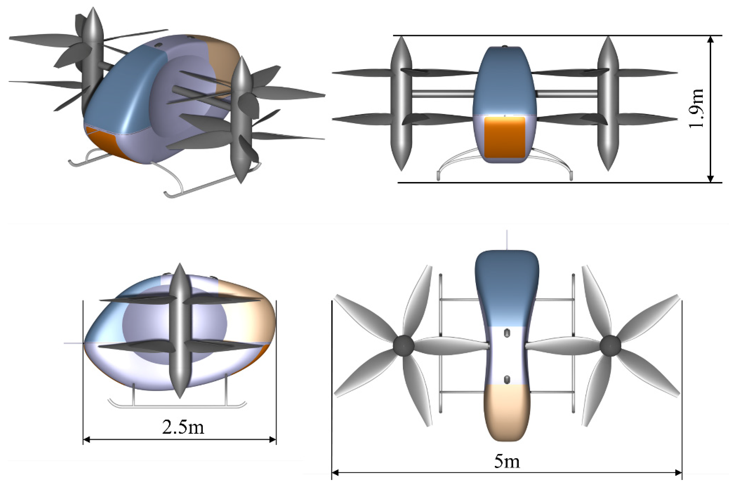
Funding

This research was funded by Aviation Science Funding Council, Aviation Industry Corporation of China (AVIC), grant number 2020Z005051002.

Institutional Review Board Statement

Not applicable.

Informed Consent Statement

Not applicable.

Data Availability Statement

The data presented in this study are available on request from the corresponding author.

Conflicts of Interest

The authors declare no conflict of interest.

Abbreviation

CRPContra-rotating propellereVTOLElectric takeoff and landing
UAMUrban air mobilityCFDComputation fluid dynamics
BEMTBlade element momentum theoryPIVParticle image velocimetry
ADMActuator disc methodRANSReynolds average Navier-Stokes
TPRThrust-to-power ratioDOEDesign of Experiments
RBFRadial basis functionMRFMultiple rotating reference frame
ALTAltitude

Nomenclature

aAxial inducible factor Ω Angular velocity
B Blade number P Propeller shaft power
bTangential inducible factor p Static pressure
β ¯ Blade pitch angle distribution Q Propeller torque
c Chord length R Propeller radius
c ¯ Chord length distribution r Radial position
C D Drag coefficient ρ Air density
C L Lift coefficient S Propeller disc area
D Propeller diameter T Thrust
F Prandtl tip loss factor U Infinity air velocity
φ Velocity forward angle V Flow velocity
Δ h Propeller spacing W Relative velocity
λ Propeller tip speed ratio W a Axial velocity
n Revolution speed W t Tangential velocity
v t Induced Circumferential Velocity v a Induced axial velocity
R h u b The radius of the hub

References

  1. Gipson, L. UAM-Overview. Available online: https://www.nasa.gov/uam-overview/ (accessed on 3 August 2022).
  2. Riboldi, C.E.D.; Gualdoni, F. An integrated approach to the preliminary weight sizing of small electric aircraft. Aerosp. Sci. Technol. 2016, 58, 134–149. [Google Scholar] [CrossRef]
  3. Wang, K.; Zhou, Z.; Fan, Z.; Guo, J. Aerodynamic design of tractor propeller for high-performance distributed electric propulsion aircraft. Chin. J. Aeronaut. 2021, 34, 20–35. [Google Scholar] [CrossRef]
  4. Alrashed, M.; Nikolaidis, T.; Pilidis, P.; Jafari, S. Utilisation of turboelectric distribution propulsion in commercial aviation: A review on NASA’s TeDP concept. Chin. J. Aeronaut. 2021, 34, 48–65. [Google Scholar] [CrossRef]
  5. Deng, S.; Wang, S.; Zhang, Z. Aerodynamic performance assessment of a ducted fan UAV for VTOL applications. Aerosp. Sci. Technol. 2020, 103, 105895. [Google Scholar] [CrossRef]
  6. Tang, J.; Wang, X.; Duan, D.; Xie, W. Optimisation and analysis of efficiency for contra-rotating propellers for high-altitude airships. Aeronaut. J. 2019, 123, 706–726. [Google Scholar] [CrossRef]
  7. Coleman, C.P. A Survey of Theoretical and Experimental Coaxial Rotor Aerodynamic Research; NASA Ames Research Center: Mountain View, CA, USA, 1997. [Google Scholar]
  8. Dorfling, J.; Rokhsaz, K. Constrained and Unconstrained Propeller Blade Optimization. J. Aircr. 2015, 52, 1179–1188. [Google Scholar] [CrossRef]
  9. Kwon, H.; Yi, S.; Choi, S.; Kim, K. Design of Efficient Propellers Using Variable-Fidelity Aerodynamic Analysis and Multilevel Optimization. J. Propul. Power 2015, 31, 1057–1072. [Google Scholar] [CrossRef]
  10. Stürmer, A.; Gutierrez, C.O.M.; Roosenboom, E.W.M.; Schröder, A.; Geisler, R.; Pallek, D.; Agocs, J.; Neitzke, K. Experimental and Numerical Investigation of a Contra Rotating Open-Rotor Flowfield. J. Aircr. 2012, 49, 1868–1877. [Google Scholar] [CrossRef]
  11. Lee, S.W.; Kim, J.K. Numerical investigation on the hovering performance of contra-rotating ducted rotor for micro air vehicle. Microsyst. Technol. 2020, 26, 3569–3580. [Google Scholar] [CrossRef]
  12. Lee, S.; Dassonville, M. Iterative Blade Element Momentum Theory for Predicting Coaxial Rotor Performance in Hover. J. Am. Helicopter Soc. 2020, 65, 1–12. [Google Scholar] [CrossRef]
  13. Van Kuik, G.A.M. Comparison of actuator disc flows representing wind turbines and propellers. J. Phys. Conf. Ser. 2018, 1037, 022007. [Google Scholar] [CrossRef]
  14. Meyer, C.J.; Kröger, D.G. Numerical simulation of the flow field in the vicinity of an axial flow fan. Int. J. Numer. Methods Fluids 2001, 36, 947–969. [Google Scholar] [CrossRef]
  15. Bontempo, R.; Manna, M. Actuator disc methods for open propellers: Assessments of numerical methods. Eng. Appl. Comp. Fluid Mech. 2017, 11, 42–53. [Google Scholar] [CrossRef] [Green Version]
  16. Khanjari, A.; Mahmoodi, E.; Ahmadi, M.H. Energy and exergy analyzing of a wind turbine in free stream and wind tunnel in CFD domain based on actuator disc technique. Renew. Energy 2020, 160, 231–249. [Google Scholar] [CrossRef]
  17. Liu, Z.; Cai, K.; Zhu, Y. Civil unmanned aircraft system operation in national airspace: A survey from Air Navigation Service Provider perspective. Chin. J. Aeronaut. 2021, 34, 200–224. [Google Scholar] [CrossRef]
  18. Toman, U.T.; Hassan, A.S.; Owis, F.M.; Mohamed, A.S. Blade shape optimization of an aircraft propeller using space mapping surrogates. Adv. Mech. Eng. 2019, 11, 1–16. [Google Scholar] [CrossRef] [Green Version]
  19. Peiqing, L. Theory and Application of Air Propeller; Beihang University Press: Beijing, China, 2006. [Google Scholar]
  20. Zhou, L.; Yan, G.; Ou, J. Response Surface Method Based on Radial Basis Functions for Modeling Large-Scale Structures in Model Updating. Comput.-Aided Civ. Infrastruct. Eng. 2013, 28, 210–226. [Google Scholar] [CrossRef]
  21. Mian, H.H.; Wang, G.; Zhou, H.; Wu, X. Optimization of thin electric propeller using physics-based surrogate model with space mapping. Aerosp. Sci. Technol. 2021, 111, 106563. [Google Scholar] [CrossRef]
  22. Liu, Z.; Albertani, R.; Moschetta, J.M.; Thipyopas, C.; Xu, M. Experimental and Computational Evaluation of Small Microcoaxial Rotor in Hover. J. Aircr. 2011, 48, 220–229. [Google Scholar] [CrossRef]
  23. Yin, S.; Zhu, M.; Liang, H. Multi-disciplinary design optimization with variable complexity modeling for a stratosphere airship. Chin. J. Aeronaut. 2019, 32, 1244–1255. [Google Scholar] [CrossRef]
  24. Zhang, Y.; Chen, H.; Zhang, Y. Numerical Research of a Propeller Plane Based on Actuator Disc Model. In Proceedings of the 7th European Conference for Aeronautics and Space Sciences (EUCASS), Milan, Italy, 3–7 July 2017. [Google Scholar]
  25. Betz, A. Development of the Inflow Theory of the Propeller; National Advisory Committee for Aeronautics: Paris, France, 1920. Available online: https://ntrs.nasa.gov/citations/19930087632 (accessed on 1 November 2022).
  26. Ma, T.; Zhang, Z.; Liu, Z.; Wang, X.; Hao, S. The rotor slipstream effects of tilt-rotor aircraft in cruise state. J. Beijing Univ. Aeronaut. Astronaut. 2021, 47, 1124–1137. [Google Scholar] [CrossRef]
Figure 1. Three-dimension views of the relevant eVTOL aircraft.
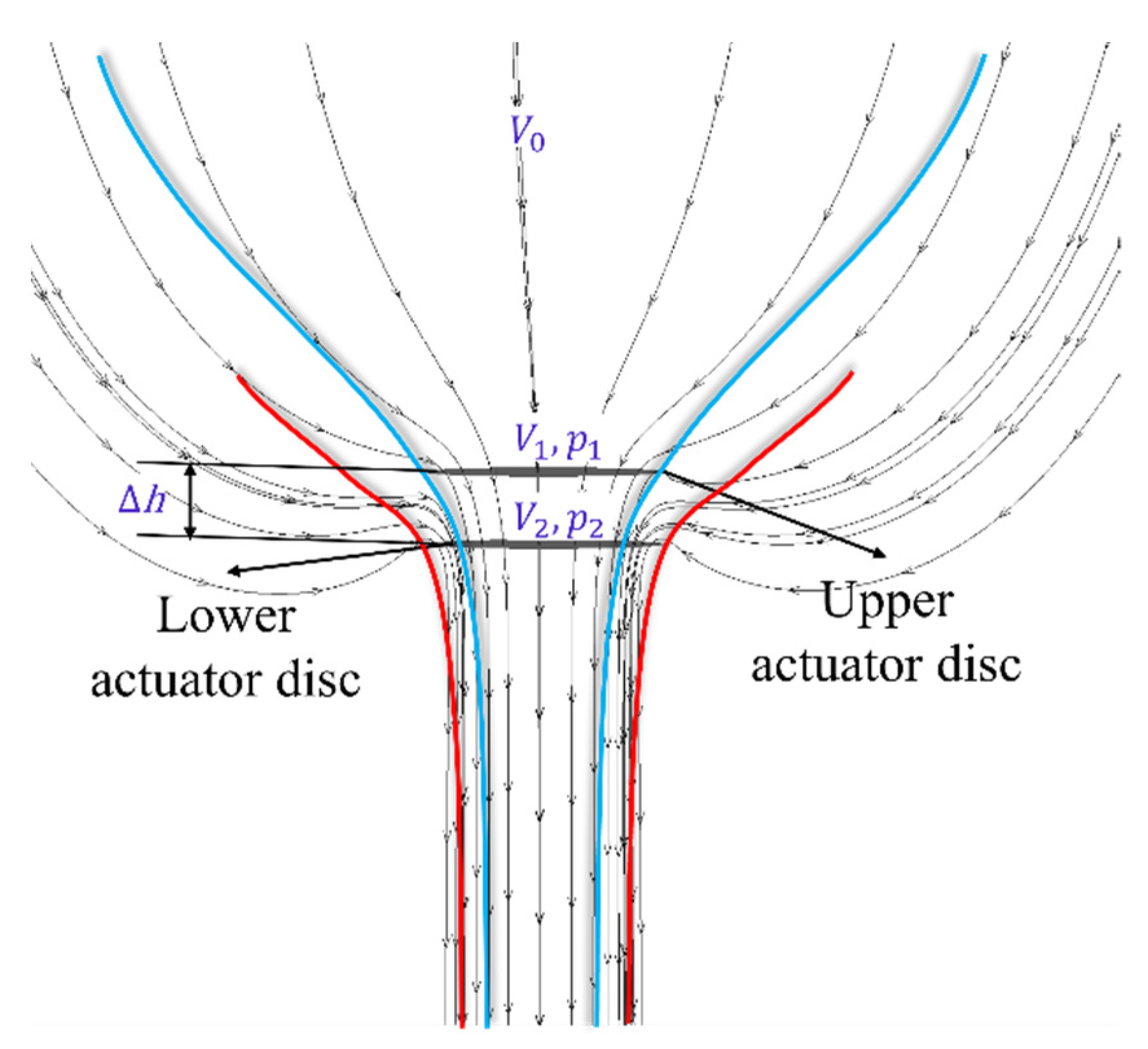
Aerospace 10 00054 g001
Figure 2. Schematics of the ideal power calculation based on actuator discs method.
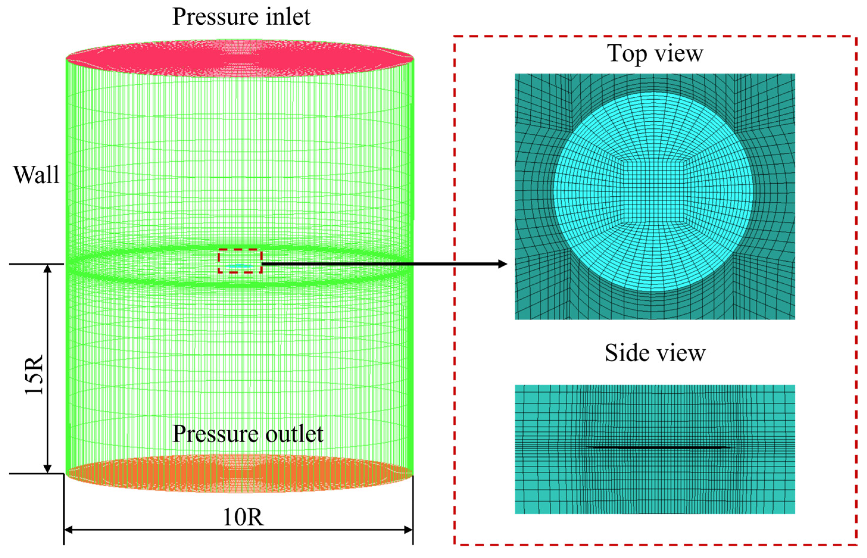
Aerospace 10 00054 g002
Figure 3. The cylindrical mesh domain of the CFD actuator disc.
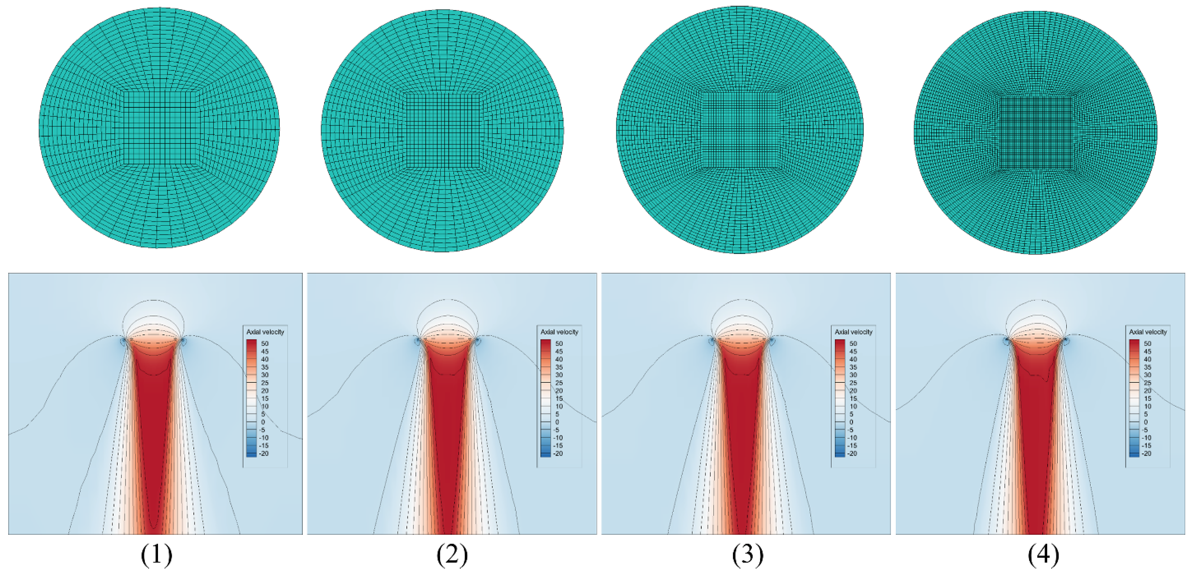
Aerospace 10 00054 g003
Figure 4. Axial velocity distributions of the four different sets of CFD actuator disc mesh with cell numbers: (1) 280,000 (2) 490,000 (3) 1810,000 (4) 34,700,000.
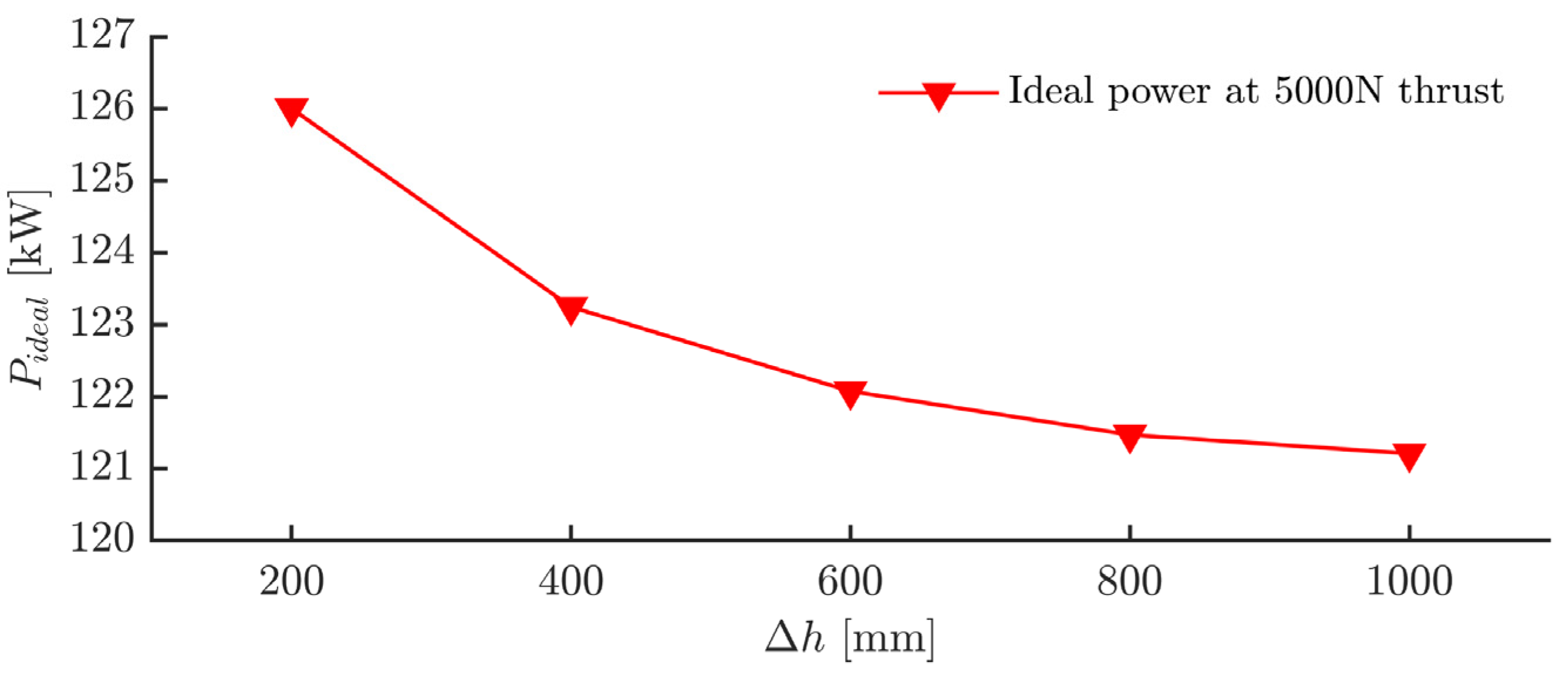
Aerospace 10 00054 g004
Figure 5. Ideal power (thrust 5000 N) of dual actuator discs with spacings from 200 mm to 1000 mm.
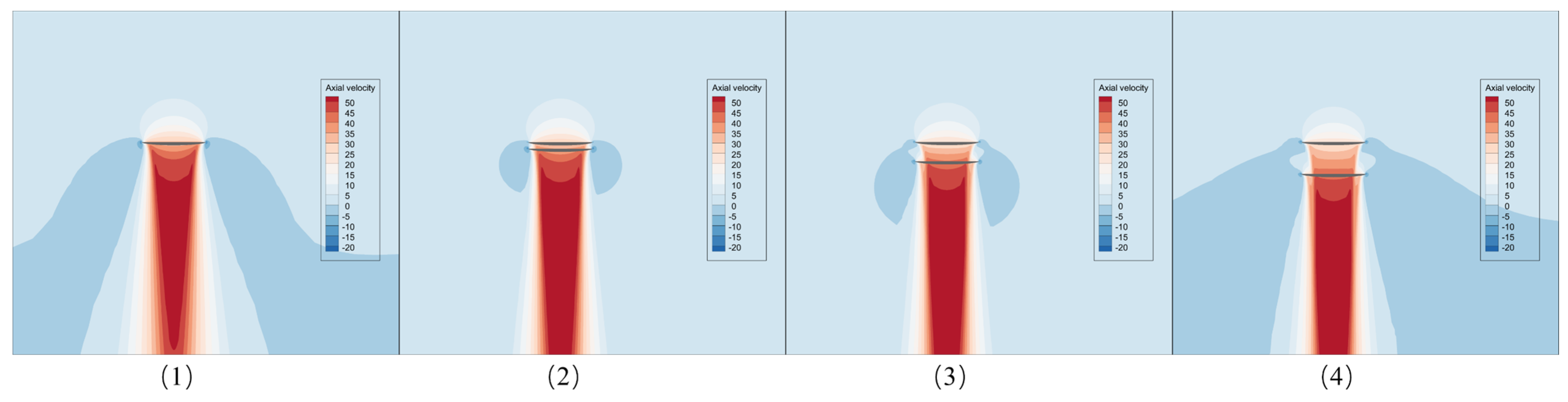
Aerospace 10 00054 g005
Figure 6. Axial velocity distributions of different spacings (∆h: (1) Single disc; (2) 200 mm; (3) 600 mm; (4) 1000 mm).
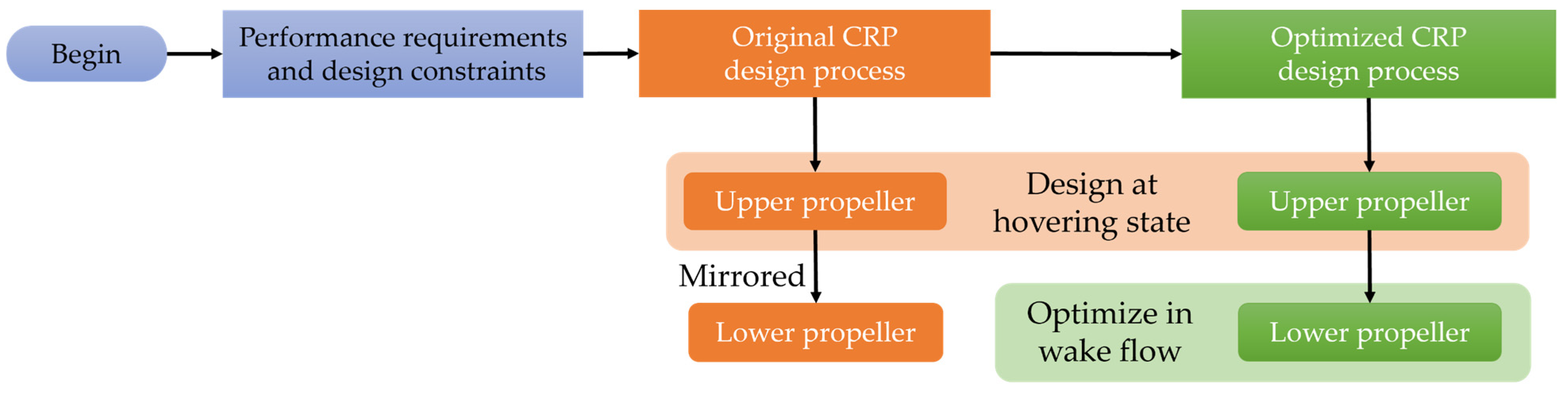
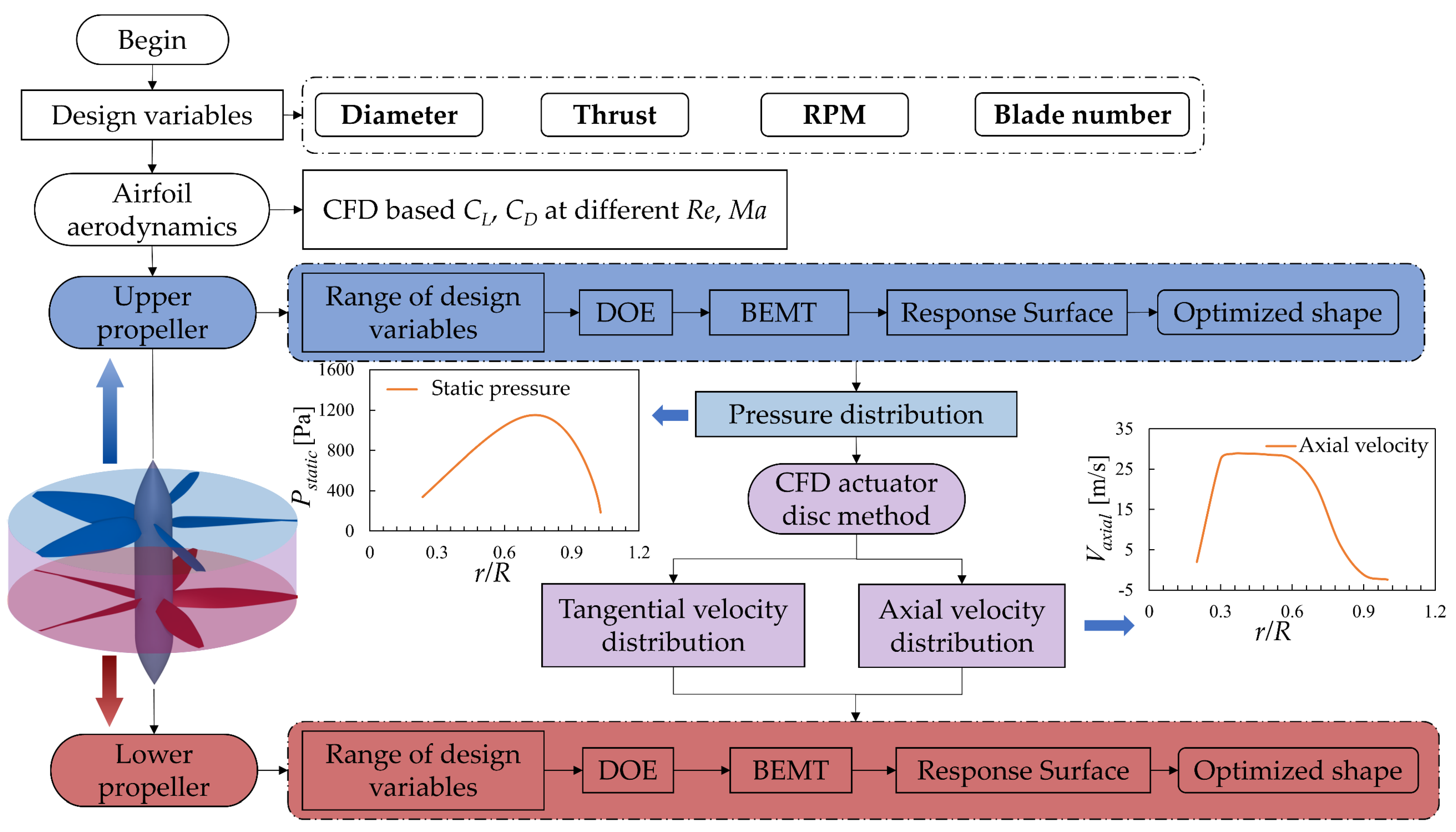
Aerospace 10 00054 g006
Figure 7. Design workflow of original and optimized CRP.
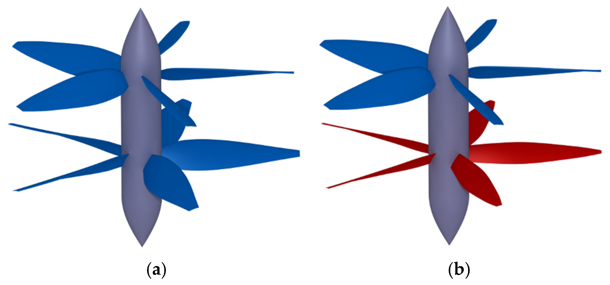
Aerospace 10 00054 g007
Figure 8. Comparison of the original and optimized CRP. (a) Original propeller; (b) Optimized propeller.
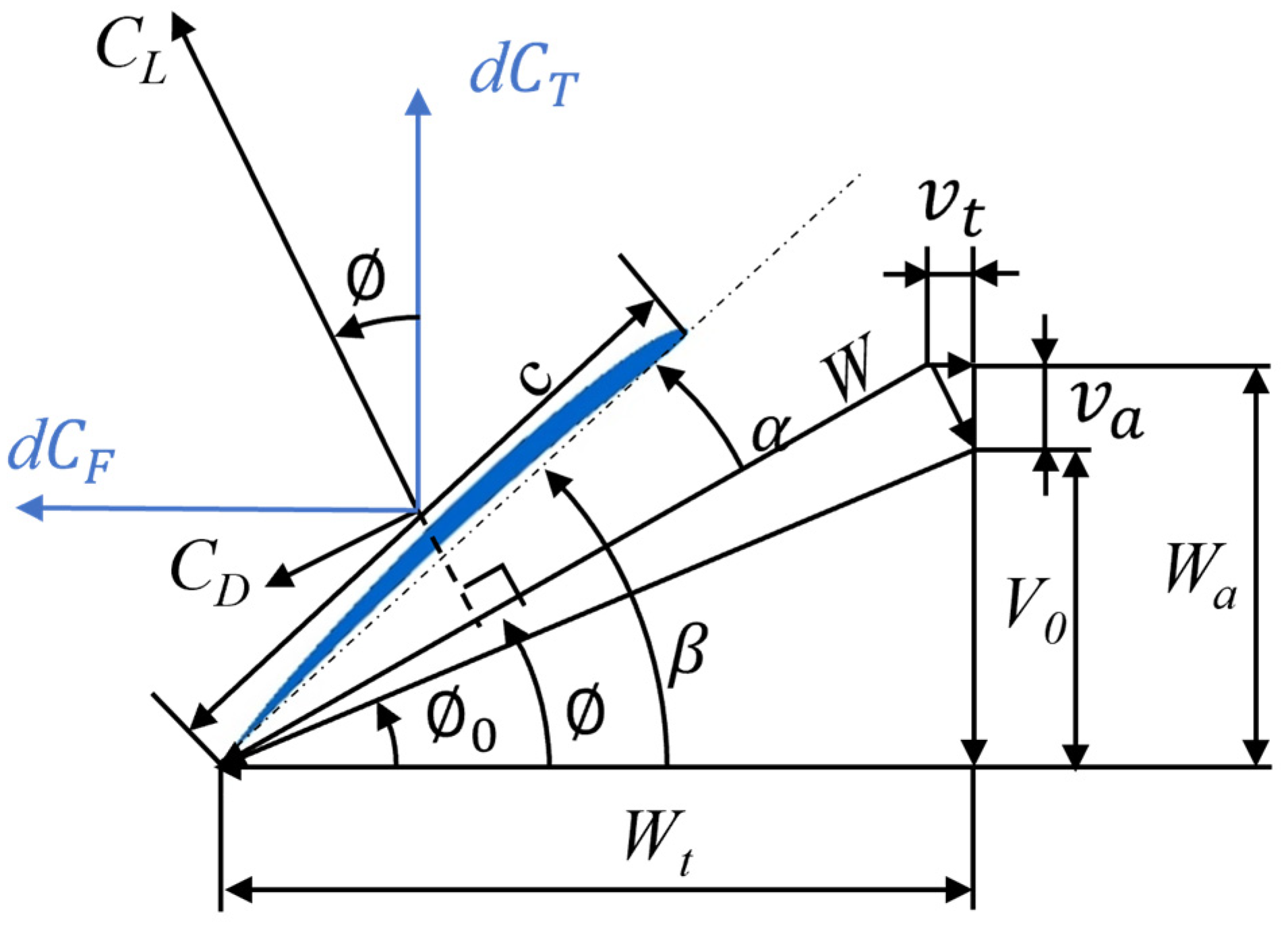
Aerospace 10 00054 g008
Figure 9. The velocity triangle of the blade element airfoil.
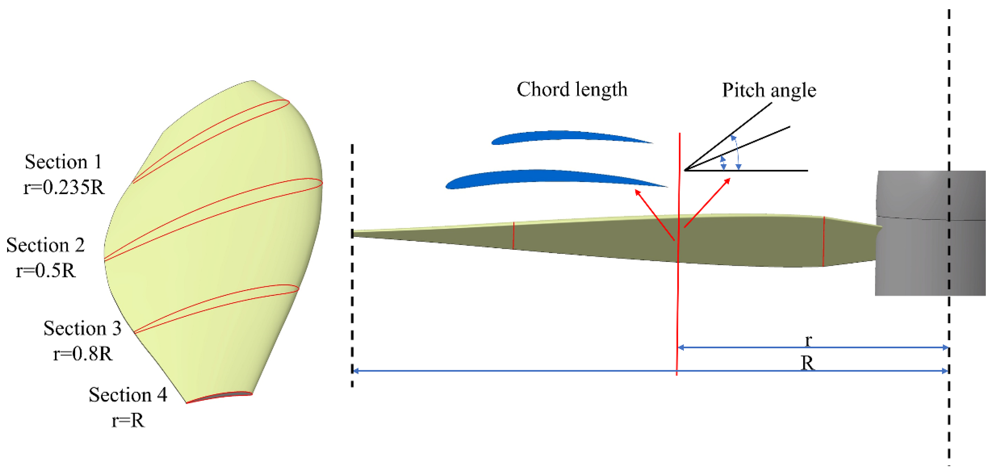
Aerospace 10 00054 g009
Figure 10. Control cross-section position and design variables (chord length, pitch angle) in optimization.
Aerospace 10 00054 g010
Figure 11. The CRP overall design optimization frameworks.
Aerospace 10 00054 g011
Figure 12. Axial velocity distribution of the wake after the upper propeller by CFD actuator disc.
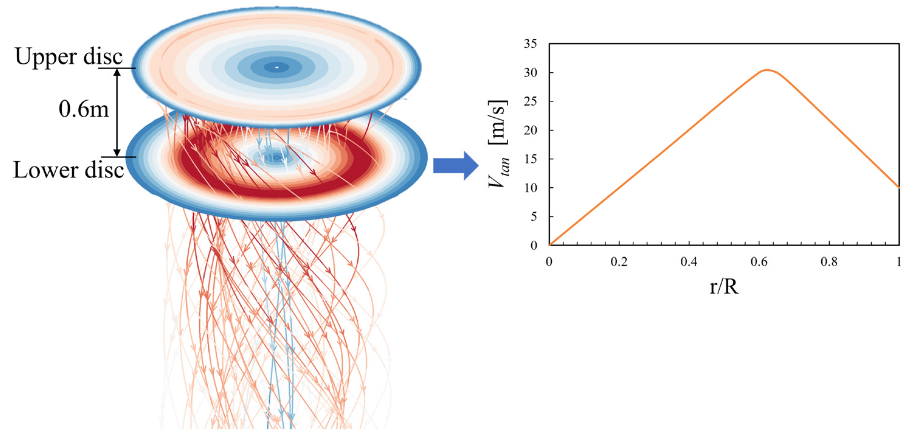
Aerospace 10 00054 g012
Figure 13. Tangential velocity distribution of the wake after the upper propeller by CFD actuator disc.
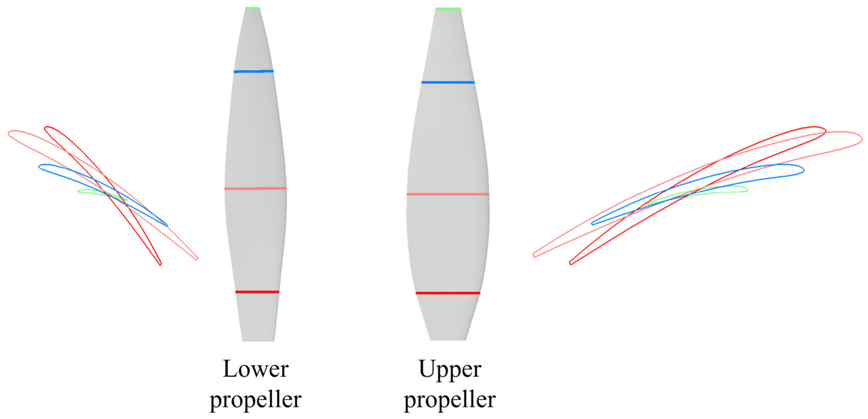
Aerospace 10 00054 g013
Figure 14. The comparison of the optimized CRP upper and lower blade pitch angle distribution on four cross-sections.
Aerospace 10 00054 g014
Figure 15. Structured periodic grid domain for Propeller CFD calculation containing stationary and rotational regions.
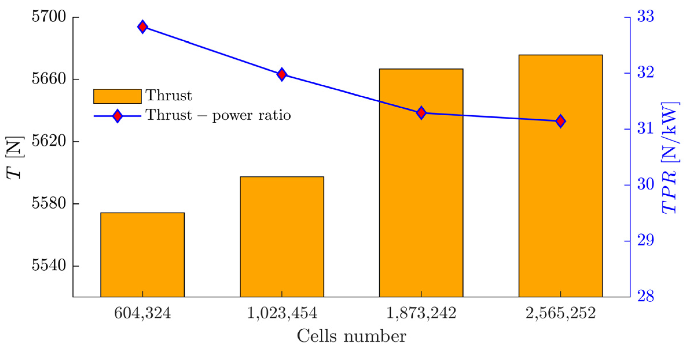
Aerospace 10 00054 g015
Figure 16. Thrust and TPR of the four grid sets for the grid independence verification.
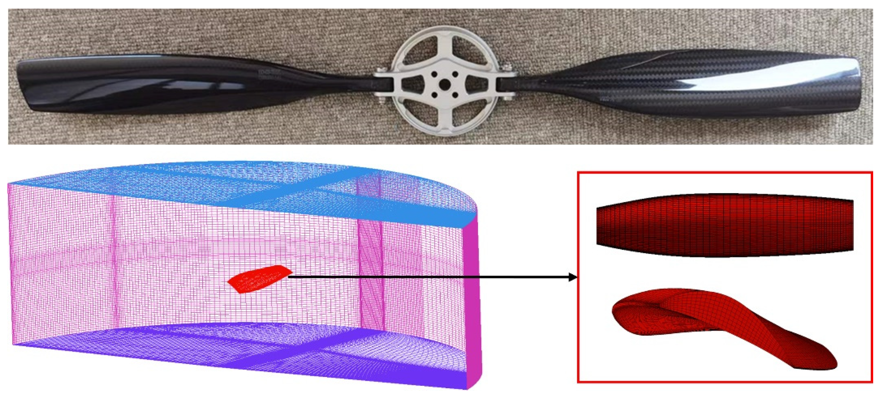
Aerospace 10 00054 g016
Figure 17. Selected propeller and its grid configuration for the MRF based CFD simulation method validation.
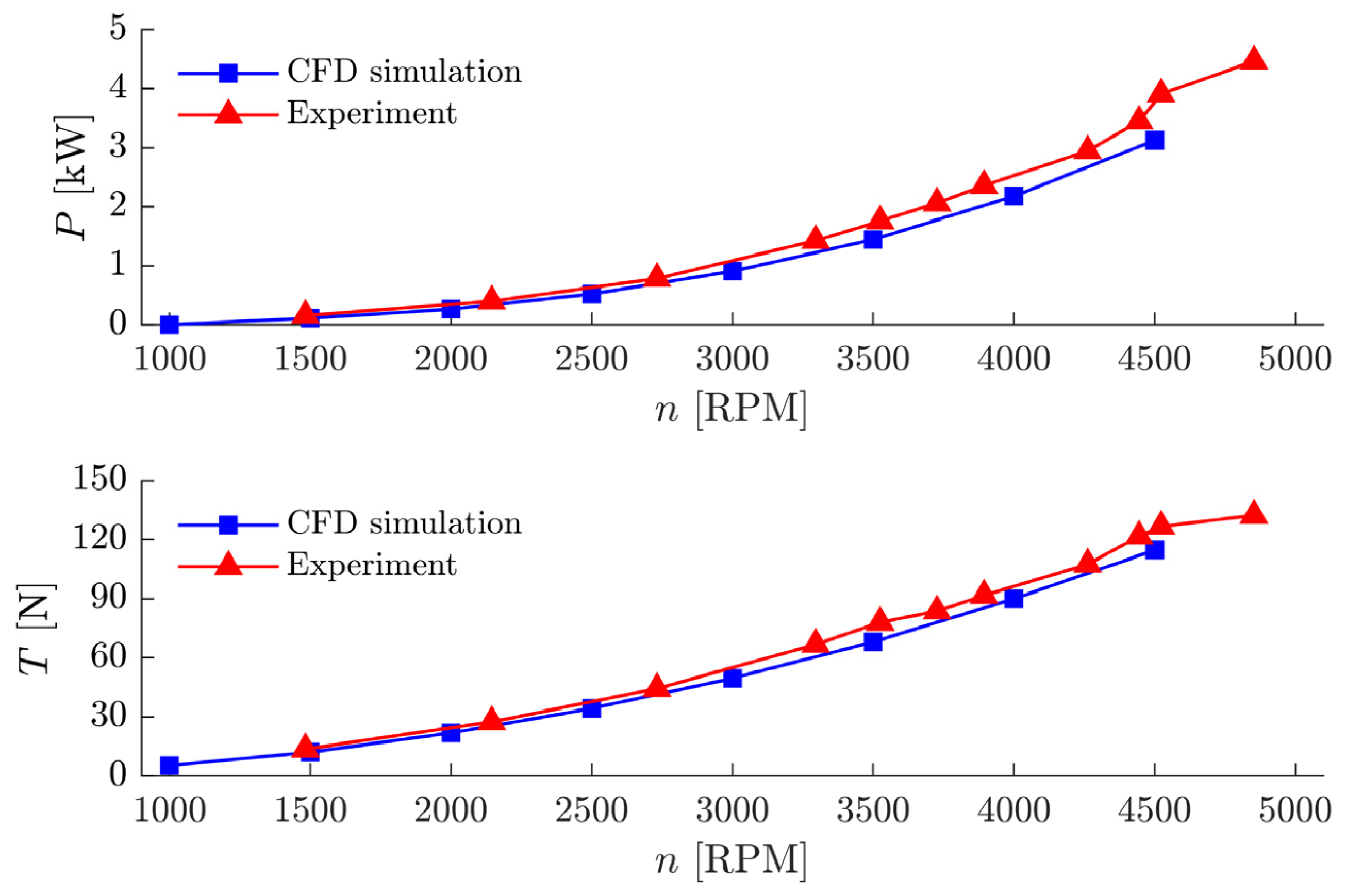
Aerospace 10 00054 g017
Figure 18. Power and thrust versus revolution speed of the two-blade propeller, obtained from experiments and CFD simulation.
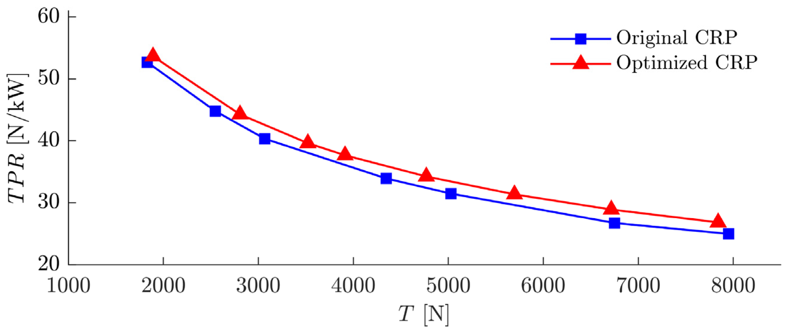
Aerospace 10 00054 g018
Figure 19. TPR comparison of the original CRP and optimized CRP.
Aerospace 10 00054 g019
Figure 20. The thrust and TPR of the optimized CRP at 5600 N thrust, with different upper and lower revolution speed allocations.
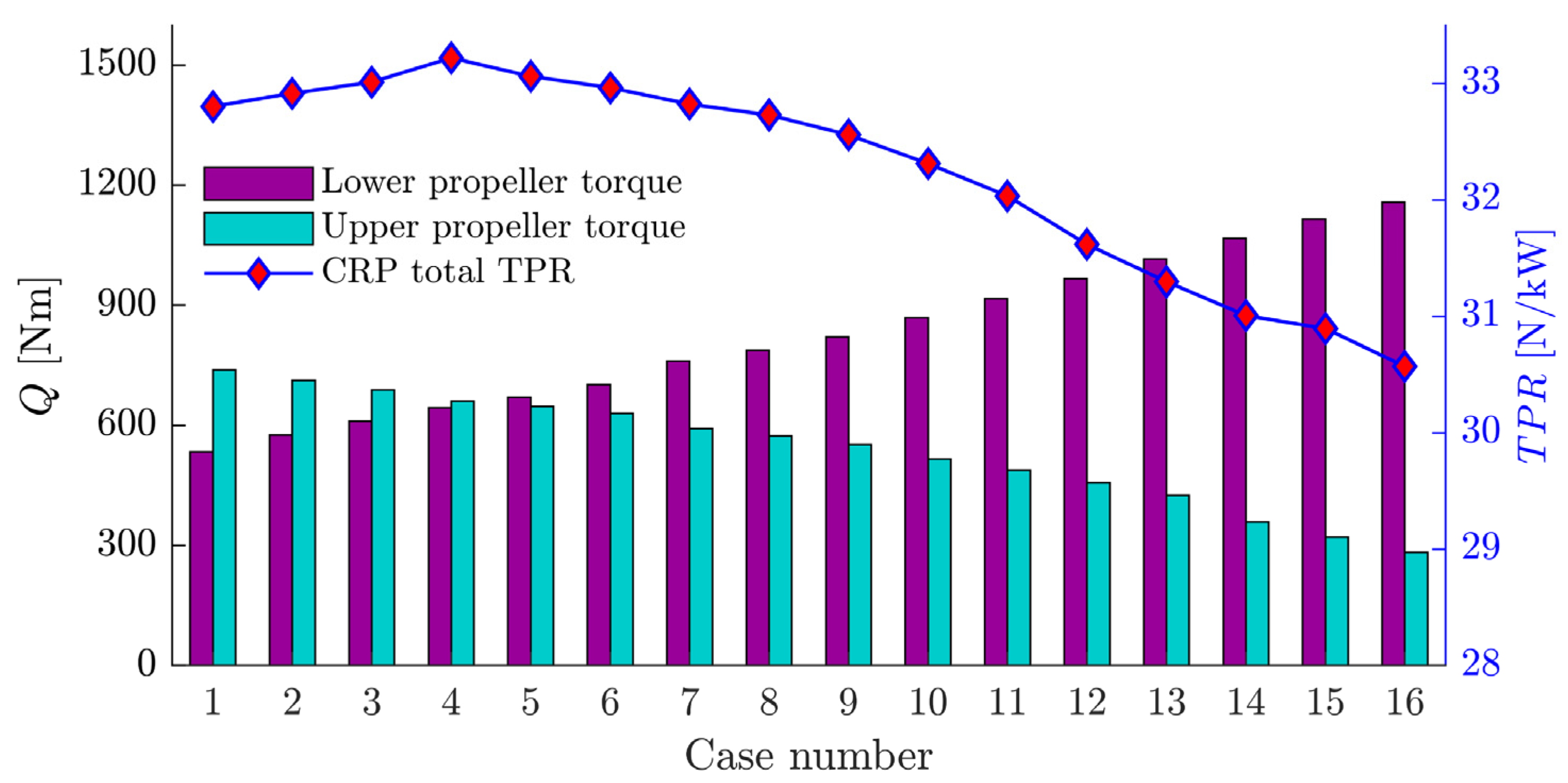
Aerospace 10 00054 g020
Figure 21. The torque and TPR of the Optimized CRP at 5600 N thrust, with different upper and lower revolution speed allocations.
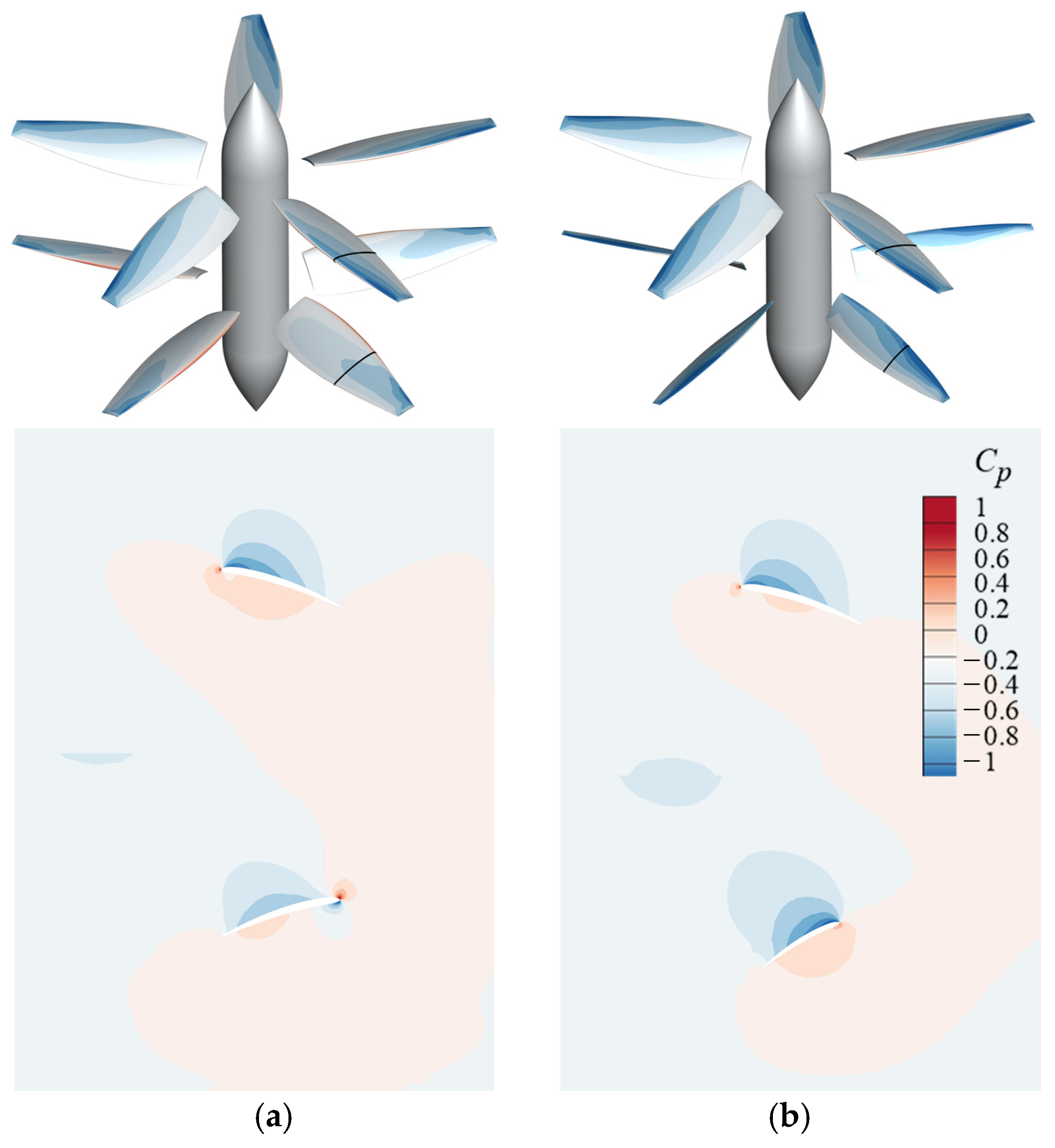
Aerospace 10 00054 g021
Figure 22. Pressure coefficient profile at 70% propeller spanwise cross-section. (a) Original CRP; (b) Optimized CRP.
Aerospace 10 00054 g022
Table 1. Salient characteristics of the eVTOL aircraft.
ParametersValue
Longitudinal length2.5 m
Transverse length5 m
Height1.9 m
CRP diameter2 m
Takeoff weight1000 kg
Table 2. Specifications of the four grid sets and flow rate calculation results.
No.Cell Number [105]Radial NodeCircumferential NodeFirst Axial Layer Height [m]Number of
Layers in the
Vertical Direction
Calculation Time [s]Mass Flow Rate [kg/s]Differences in
Percent between the Mass Flow Rates
12.855600.02550348101.18100.37%
24.960800.0260480101.23100.4%
318.1901200.015901366101.1100.29%
434.71101600.011102375100.8100%
Table 3. Ideal power of dual discs with different propeller spacings at a thrust of 5000 N.
Δ h P i d e a l P i d e a l / P sin gle - disc
Single disc130.7091
200126.0040.964
400123.2480.943
600122.0780.934
800121.4730.930
1000121.2120.928
Table 4. Parameters related to the CRP optimization.
ClassificationDefinitionsSymbolsValue
Condition parametersAir density ρ 1.16 kg/m3
Altitudeh500 m
Air viscosity μ 1.78 × 10⁻⁵ Ns/m2
Predetermined parametersDesign thrust T 2800 N
Propeller diameter D 2 m
Blades number B 5
Revolution speed n 1200 rpm
Airfoil for blade cross-section-ARA-D
Design variablesChord length distribution c ¯ -
Pitch angle distribution β ¯ -
Optimization objectiveTPR T / P -
Table 5. Design variables range defined and optimization results for the upper propeller in original CRP.
r/RVariables RangesOptimization Results
Chord Length [m]Pitch AngleChord Length [m]Pitch Angle
0.2350.15~0.2522°~35°0.226.85°
0.50.2~0.3515°~25°0.2618.9°
0.80.15~0.2510°~20°0.18412.9°
10.05~0.153°~10°0.0754.58°
Table 6. The blade shape optimization parameters and conditions for the optimized CRP.
Optimized CRPUpper PropellerLower Propeller
Design thrust2800 N
Revolution speed1200 rpm
Diameter2 m
Optimization conditionsHovering statusWake of the upper
Table 7. Design variable range definition and optimization result of the lower propeller in the optimized CRP.
r/RVariables RangesOptimization Results
Chord Length [m]Pitch AngleChord Length [m]Pitch Angle
0.2350.1~0.2535°~60°0.1450.3°
0.50.1~0.3520°~50°0.1834.38°
0.80.08~0.2515°~30°0.1225.95°
10.03~0.155°~15°0.0410.7°
Table 8. Upper and lower propeller revolution speed allocations for the optimized CRP at 5600 N level thrust.
Case
Number
Upper Revolution Speed [rpm]Upper Torque [Nm]Lower Revolution Speed [rpm]Lower Torque [Nm]Total Thrust [N]TPR [N/kW]nupper/nlower
11532.00738.71935.00533.175599.8632.801.64
21507.00712.67960.00576.155608.1332.911.57
31484.00689.19980.00610.615604.1833.011.51
41467.21660.001000.00643.705607.7333.221.47
51442.60648.001015.00670.505592.4533.061.42
61425.25630.541034.00701.875607.1632.961.38
71386.20592.321067.00760.915612.4932.821.30
81368.63573.751080.00787.595606.5432.731.27
91344.18551.531100.00821.585608.8232.561.22
101305.95516.101125.00869.445590.0932.311.16
111264.20488.251150.00917.235608.8332.031.10
121225.02456.161175.00967.135612.4831.621.04
131200.00425.001200.001015.875666.7331.561.00
141164.00359.281225.001067.605604.1831.010.95
151061.88320.671250.001114.835610.0130.890.85
16993.15282.411275.001157.375621.4830.570.78
Table 9. TPR comparison (at 5600 N thrust) of the original CRP and optimized CRP (equal revolution speed of Case 13, and trimmed revolution speed of Case 4).
Propulsion UnitTPR at 5600 N [N/kW]
Original CRP29.80
Optimized CRP (equal revolution speed)31.56
Optimized CRP (trimmed revolution speed)33.22
Disclaimer/Publisher’s Note: The statements, opinions and data contained in all publications are solely those of the individual author(s) and contributor(s) and not of MDPI and/or the editor(s). MDPI and/or the editor(s) disclaim responsibility for any injury to people or property resulting from any ideas, methods, instructions or products referred to in the content.

