
LoRaWAN CubeSat with an Adaptive Data Rate: An Experimental Analysis of Path Loss Link Margin

School of Aerospace Engineering, Universiti Sains Malaysia, Nibong Tebal 14300, Penang, Malaysia
*
Author to whom correspondence should be addressed.
Aerospace 2023, 10(1), 53; https://doi.org/10.3390/aerospace10010053
Submission received: 3 December 2022
/
Revised: 30 December 2022
/
Accepted: 2 January 2023
/
Published: 4 January 2023
(This article belongs to the Special Issue Advanced Small Satellite Technology)
Abstract
:One of the challenges of the Internet of Things (IoT) is to provide connectivity to devices around the globe. Long Range (LoRa) is one of the most practical technologies due to its low-power and long-range capabilities to be used by the Low Earth Orbit (LEO) CubeSat. This study aims to evaluate the performance of the Long Range Wide Area Network (LoRaWAN) in receiving uplink messages from ground sensor nodes at an altitude of 550 km with a maximum elevation angle of 0°. An Adaptive Data Rate (ADR) is applied for the dynamic signal reception with respect to receiving signal strength. In this study, the path loss is simulated using attenuation levels from 30–150 dB to ensure that the signal connectivity success rate is at a minimum elevation angle and to perform the link analysis under various conditions. The results show that the LoRaWAN signals are successfully received with an SNR of −21 at the 150 dB attenuation from the end nodes because of its spread-spectrum technique which allows the system to detect signals under the noise floor.
1. Introduction
The Internet of Things (IoT) has made it possible to connect sensor devices in a variety of ways. Sending data directly from sensor devices on the ground to the satellite is one of the most intriguing methods, as every end node will have independent connectivity to the spacecraft. Long Range Wide Area Network (LoRaWAN) is one of the promising platforms for this direct IoT implementation because of its low-power and long-range capabilities. Sensor nodes can communicate directly with spacecraft orbiting in Low Earth Orbit (LEO) without relaying data to a local gateway using the Direct-to-Satellite (DtS) method. This DtS-IoT approach is used to overcome a problem in areas where there are no internet services; Figure 1 compares the concept of DtS and the ground data relay architecture. In addition, sending data first to a ground gateway and then relaying all those data to a satellite will present an issue whenever the ground gateway is down for some reason. In this regard, all sensors connected to that gateway will lose communication, and there will be an outage for that region. Therefore, the DtS approach is more practical because if any sensor were to lose contact with the ground gateway, it would not affect the whole area. Numerous studies are being conducted to improve and enhance the DtS-IoT concept. Several missions and studies, ranging from CubeSats to Nano Satellites, have been carried out so far.
Satellite communication is an effective way to connect various points on earth. LEO missions have recently been explored to establish optimal low-cost and low-power transmission [1]. However, the spacecraft’s sight window is relatively small due to the faster orbital speed of LEO and its low altitude. Additionally, the devices on earth are considered low-power solutions. Therefore, achieving greater distances in LEO is challenging despite path loss attenuation and atmospheric as well as Doppler shift.
One of the challenging parts for the IoT small satellite is the assurance of reception to the sensor devices which are trying to establish a direct connection to the satellite. Several technologies are evolving for IoT services; some are even introduced as real-time solutions. However, when it comes to long-distance low-power communication, LoRa is one of the most promising technologies to overcome this issue. Although extensive research has been conducted along with a brief analysis of LoRa technology, ref. [2] demonstrated NORBY nanosatellite using a LoRa modulation transmitter. NORBY has tested LoRa with different spreading factors and bandwidths. However, NORBY’s radio communication used LoRa modulation, which is sufficient for the point-to-point communication relay and cannot be implemented as a star topology while creating sensor networks. In another work [3], KITSUNE CubeSat was a mission designed to develop a sensor network using the LoRa module. KITSUNE used eight separate LoRa transmitter chips to create eight receive frequency receptions which is by far the best solution to create a network of sensors. However, this research was still limited to LoRa modulation and did not use the Adaptive Data Rate (ADR) options. In [4], Thomas proposed a CubeSat using LoRaWAN and replicating the LoRa signal by using a USRPB205 mini transceiver which verifies the significance of LoRaWAN architecture for the CubeSats. Nevertheless, replicating LoRaWAN by software-defined radio (SDR) is not cost-effective and will not properly demonstrate the patented Semtech LoRaWAN transmitter. The proposed method in our study illustrates the LoRaWAN architecture in the context of the pertinent literature with a single main transmitter module, RAK2245, along with the ADR option. In addition, the signal receptions are optimized according to the received signal strength, making it perfect for the 1U CubeSat with the minimal necessary power.
The key option in LoRaWAN architecture to allow more flexibility in signal processing is using ADR [5]. ADR allows the system to choose the best signal level, even in the worst scenario, in terms of power and Carrier-to-Noise Ratio (CNR). Moreover, in the case of the LEO satellite carrying the LoRaWAN gateway, when the spacecraft is at the maximum distance (at minimum elevation look angle), the signal level will be adjusted as per the reception of the received signal. Meanwhile, when the spacecraft is at the minimum distance from the ground station, the data rate will be adjusted to the maximum, and the time-on-air transmission rate will be improved. In addition, nodes are configured to send only two frames per pass to counteract the Doppler shift.
This study aims to investigate the signal propagation integrity of the 433 MHz frequency band, and the capability of a low-earth orbiting satellite carrying a LoRaWAN payload as the gateway to collect data from the nodes on the ground area without internet connectivity. The signal level and the capability of service delivery at the LEO, which is around 550 km altitude, are investigated. ADR is used to analyze the signal adaptation of dynamic signal selection at the worst-case scenario and the reception of nodes at the gateway level. The data from the gateway are then dumped into the ground station as the satellite passes the ground station. Additionally, the link budget is considered in this study while analyzing the signal integrity and path loss output at the end nodes. Multiple attenuators were employed to simulate the signal at various distances to determine the practical link performance.
This paper is divided into six sections: Section 2 provides the literature review on the related works from previous studies. Section 3 gives an overview of different IoT technologies and their modulation comparison, along with the pros and cons. Section 4 is the methodology that covers the theoretical aspects of this study and link budget calculation. There is also an explanation of the hardware setup and how the path loss is simulated to achieve maximum distance. Section 5 is the results obtained by performing the experiment. Finally, Section 6 is the conclusion of this study.
2. Related Work
LoRa is a versatile and promising technology for connecting low-powered sensor devices because of its versatility. In recent years, a considerable number of studies have been conducted. Researchers are investigating every possible element and application of LoRa technology. One of the factors to consider is how far the signal can travel and LoRa’s maximum range before the signal degrades. In [6], the study proposed the internet in space for small satellites. They demodulated the signal using Semtech SX1276 and transmitted it from LoRa MAC to Ethernet. Despite the fact that this design satisfies the Direct-to-Satellite (DtS) requirements, the greatest calculated distance was 30 km when tested using a High-Altitude Balloon (HAB). Using a microchip LoRa transmitter, Carlos et al. [7] designed a communication subsystem for the Unmanned Aerial Vehicle (UAV) wireless sensing network. It was thoroughly tested by UAV, but the longest distance recorded was 8.62 km at an altitude of 30 m above the ground, which does not meet the satellite communication requirements. Using an IMST IC880A LoRaWAN concentrator and an RN2483 LoRa node, Pierre Neuman et al. [8] tested the LoRaWAN gateway. It was tested indoors, and the highest node distance observed was 60 m, which is again restricted to terrestrial connectivity. Parri et al. provided a solution for marine monitoring activities by using LoRaWAN network architecture [9]. The onshore signal performance degrades due to the collision of air molecules and dense humid environment. The proposed system satisfies the performance needs; however, the maximum recorded distance was 8.3 km and the authors suggested to increase the height of antenna for the increase in coverage area. Chen et al. designed a DtS-IoT ground terminal for environmental monitoring using the Xingyun IoT satellite [10]. The design of the transceiver is based on the Xingyun satellite communication protocol with a much lower transmit power of 30 dBm with both uplink and downlink reception. The research satisfied the DtS-IoT connectivity by using the Xingyun satellite and obtaining the data from the ground station over the internet. The research was focused on using the Xingyun satellite services using patented satellite transceiver names such as LEOBIT. Meanwhile, Rachel et al. [11] suggested an ADR algorithm based on fuzzy logic for LoRaWAN gateway systems. Even though that research demonstrated superior performance in terms of energy consumption and transmission power compared to the Semtech ADR scheme, it showed that the Semtech ADR scheme is ideal in terms of energy consumption. However, in satellite LoRaWAN communication systems, it can only be helpful when the handoff between coupled satellites occurs.
Comparison of Ongoing Missions with Present Research
An analysis of previous research and successful missions is shown in Table 1. The table compares the slant range distance, minimum elevation angle, RSSI, SNR, data rate factor and network topology mode. The ongoing mission parameters were taken from the community website TinyGS [12]. The proposed study shows that the spacecraft carrying a LoRaWAN gateway with ADR, even with the minimum gain, has signal integrity and a high receive strength. Moreover, a comparison has been made with the LoRa payload alongside the LoRaWAN gateway, which this study uses to allow the star topology of the network with ADR.
The main contribution of this paper is to investigate the maximum possible range of the LoRa signal while communicating to the LoRaWAN gateway on the satellite. It was tested by attenuating the signal at its maximum fade range, which will be explained in Section 4. To further improve the link availability, an ADR scheme is added to the communication subsystem, so when the signal is reaching its maximum range and unable to keep the link stable, the system will automatically adjust the quality by changing the spreading factor.
3. IoT Technology Evolution
IoT has now become a rapidly growing global network for interconnecting devices. Four of the most extensively utilized Low Power Wide Area Network (LPWAN) technologies today are SigFox, Zigbee, NarrowBand-IoT (NB-IoT) and LoRa. These technologies’ physical or MAC layer features are compared based on the modulation-coding methods, frequency band, power and other parameters, as well as their performance. Table 2 summarizes the comparison of the different IoT emerging technologies.
As per the technology comparison in Table 2, some of these technologies utilized licensed bands, while others utilized unlicensed bands, which everyone can use freely. SigFox technology uses unlicensed industrial, scientific and medical radio (ISM) channels, Binary Phase Shift Keying (BPSK) and Gaussian Frequency Shift Keying (GFSK) for modulation [17]. Because of the modulation utilization at specific frequencies, it is feasible for SigFox to broadcast at 22 dBm and receive at 126 dBm. Due to its capacity to compensate for a frequency drift of up to 30 Hz, SigFox can achieve data rates of up to 600 bits per second, depending on the location. For instance, Nashiruddin and Yusri proposed network coverage planning for metered devices by using SigFox in the dense urban environment [18]. Their research focused on smart IoT uses for terrestrial connectivity of low-powered devices within the coverage area of 8 km which demonstrated the real time use of SigFox technology. Additionally, the MAC layer protocol can accommodate the delays associated with communication through LEO satellites. Due to SigFox’s exclusive right to deploy base stations, other firms are unable to install gateways aboard spacecraft.
Another low-powered sensor technology open standard is Zigbee. Zigbee is based on IEEE 802.15.4 for wireless personal area networks, which operates on 868 MHz, 915 MHz and 2.4 GHz, followed by the modulation of DBPSK and OQPSK [19]. As shown in Table 1, Zigbee enables 10–100 Kbps, the promising highest data rate technology amongst other low-powered technologies. However, Zigbee has a limited range of 30–50 m; thus, it is impossible for it to enable the connectivity of ground sensors to low earth orbit spacecraft. Moreover, in order to make use of Zigbee over satellite several steps should be taken. For example, Sturdivant et al. proposed IoT satellite connectivity using ZigBee architecture to monitor the power generation system where they used the Iridium satellite transceiver for the backhaul connection over satellite [20]. Although this research provides a solution of using ZigBee over satellite, this approach does not satisfy the DtS. In addition, the backhaul link using the Iridium satellite transceiver significantly increases the cost of the system because of the transceiver cost as well as monthly billing.
According to the LPWAN standard, the 3GPP created NB-IoT, also known as cellular LPWAN. It is currently a component of both 4G and 5G networks. When operating within the licensed spectrum for this technology, the modulation method is Quadrature Phase Shift Keying (QPSK). The maximum transmission power is 23 dBm with a depth sensitivity of −125 dBm. In addition, the data transfer rate from the base station to the end devices may reach 250 kbps at its peak but drop as low as 26 kbps at its lowest. Delay and Doppler are critical concerns for the NB-IoT signals and its physical layer. Therefore, this protocol will need to be modified to make use of it in Satellite-to-Earth communications. Mobile Network Operators (MNO) are also responsible for base station installation. The importance of IoT technology over satellite connectivity was highlighted by Routray et al. in their article [21]. Although Routray et al. addressed only military application in which they proposed the idea to monitor different aspects of military surveillance over NB-IoT, it shows the significance of IoT technology over satellite links. Conti et al. suggested a Doppler correction solution for NB-IoT user end devices, considering it to connect the base station over satellite link [22]. Their research is valuable and adds to past concepts of NB-IoT improvement; however, the main focus was on the ground data relay architecture, which does not meet the problem addressed in this research.
Semtech pioneered the LoRa wireless technology that is still in use today. This technology can transmit up to 22 dBm of output power with a sensitivity of up to −139 dBm and a data rate of up to 27 kbps. The Chirp Spread-Spectrum (CSS) modulation technique is utilized, which is more resistant to interference and jamming than other modulation techniques. Furthermore, it communicates through unlicensed ISM bands that are less crowded than licensed channels. In LoRa operation, various settings of the transceivers need to be tuned, including the transmit power, bandwidth, code rate, and spreading factor. LoRa may be utilized with a number of different MAC layer protocols, the most generally used being LoRaWAN. LoRaWAN is a free, open-source wireless network protocol optimized for battery-powered end devices. Numerous suppliers provide commercial off-the-shelf (COTS) LoRa nodes and gateways. As a result, it is a good approach to propose a LoRaWAN satellite built-in gateway in the future.
4. Methodology
In this study, two approaches have been established to investigate the end nodes LoRa signal performance. The first method is the theoretical analysis of the orbit geometry for LEO satellites with respect to the ground observer. The second method is an experiment simulating the path loss using the 0−150 dB attenuation levels with a step of 30 dB. The purpose is to prove that the LoRaWAN with ADR capability enables direct connectivity from the end nodes to the satellite.
4.1. Theoretical Analysis
4.1.1. Orbit Geometry and Slant Range Analysis
The positioning of LEO satellites is challenging because the satellite continually moves at a constant angular velocity when seen from an Earth point ground station. Before calculating the free space path loss from the satellite to the antenna, the distance between the satellite and the ground station antenna must first be determined. The topocentric reference frame is used to track in an arbitrary orbit from a point on the ground and usually requires the computation of quantities slant range azimuth and elevation [23]. Two approaches to computing these are cartesian geometry and spherical geometry.
If the cartesian coordinates of the satellite in the Earth-Centered Fixed (ECEF) coordinate frame are denoted as and the ground observer located at the longitude and latitude , the cartesian coordinates of the ground observer will be denoted by Equations (1)–(3). Figure 2 shows the geometrical representation of the ground observer.
Then the slant range vector from ground to spacecraft will be calculated by Equation (4).
To transform into topocentric coordinates , it is observed that the topocentric coordinates involve rotation along the z axis by angle and rotation along the y axis by angle ). Therefore, the coordinates can be calculated by Equation (5).
Hence, the slant range d can be calculated using Equation (6).
Also, azimuth and elevation angles are calculated using Equations (7) and (8).
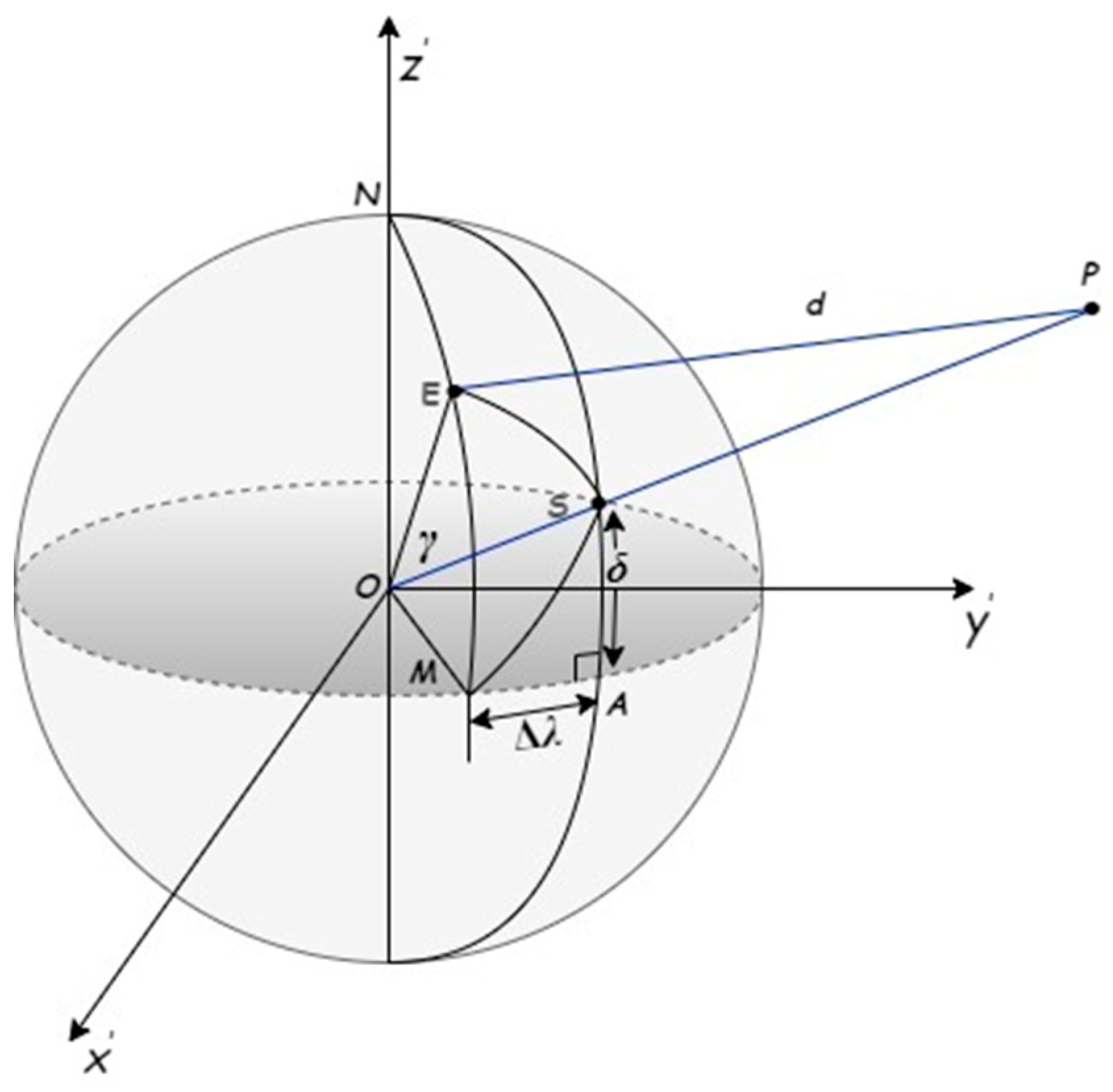
In spherical geometry, local mean sidereal time, the angle of a ground station at latitude is the angle between the vernal equinox and measured positive towards the east. The geometry between the Earth station and the spacecraft with sub-satellite point S is shown in Figure 3.
The hour angle H of the satellite measured positive to the west is the relative longitude between E and S. It is denoted as Equation (9):
In Figure 3, the spherical triangle is redrawn to compute central angle γ subtended by circle arc ES, and the law of cosines is applied to the sides as shown in Equations (10) and (11).
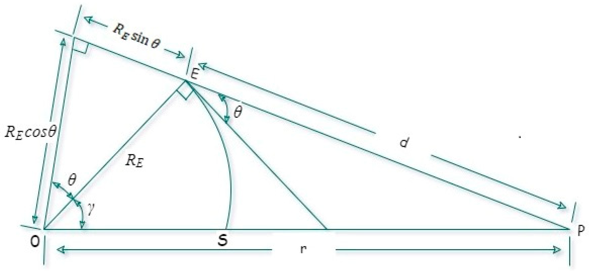
Slant range can be determined by applying cosine laws to the plane triangle using Equation (11), as shown in Figure 4.
Hence the azimuth angle can be calculated using Equations (12) and (13).
Applying the law of sines to a plane can achieve triangle elevation angle θ using Equation (14).
4.1.2. Link Budget Analysis
To evaluate the maximum link coverage performance of the test modules, the end-user configuration with a transmit power of 20 dBm is implemented using the SX1278 transceiver. For the payload, the LoRa gateway with the SX1301 module is used. This experiment uses a frequency of 433 MHz with 8 channels capacity and a carrier spacing of 0.25 MHz. Each carrier is ADR-enabled and has the ability to automatically adjust the SF as per the received signal strength. Half-wave dipole antennas are used for both ends with a gain of 2.5 dBi. The gateway module has a noise figure of 6 dB and transmits a power of 27 dBm. Receive sensitivity can be obtained using Equation (15) [24],
where BW = Bandwidth in kHz,
NF = Noise Figure of the receiver in dB,
SNR = Signal-to-Noise Ratio as per spreading factor,
S = sensitivity in dB.
To calculate the path loss, a link performance in Equation (16) is used,
where = Transmit Power,
= Receive power,
= System Gains,
= Losses,
= Channel Propagation Losses,
M = Fading Margin.
The Free Space Path Loss (FSPL) is then calculated using Equation (17),
where d = Antenna distance between receiver and sender
= Frequency
= Speed of light
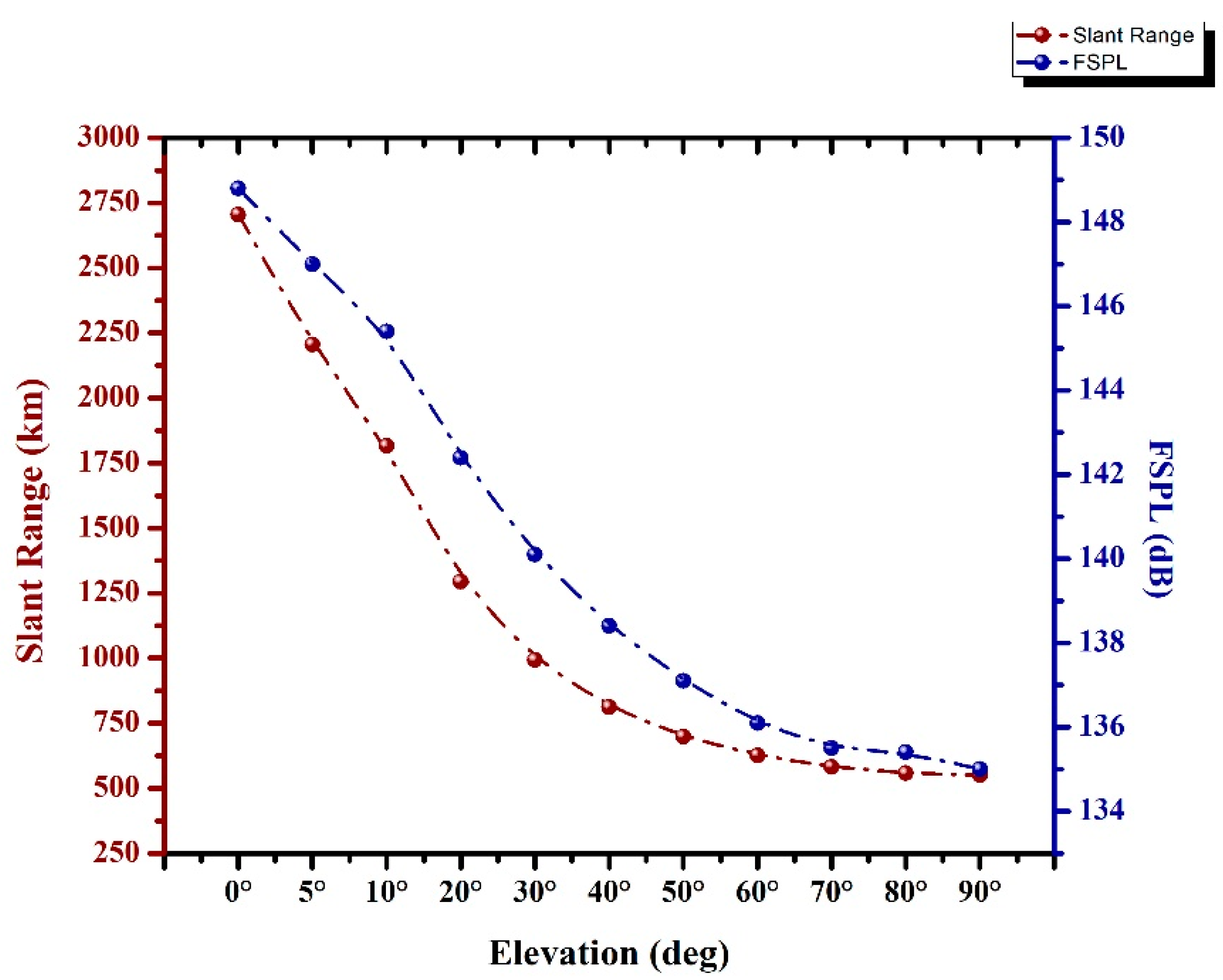
Due to the slant range, different angles will have an additional fade margin. Table 3 shows the path loss comparison concerning the slant range using Equations (11) and (17).
4.1.3. Slant Range Analysis
In the context of the above methodology, the visibility of spacecraft as per slant range is possibly denoted from 0 to 90°. However, in practice it is fairly difficult to communicate with spacecraft due to urban obstacles at the lowest elevation angle [25]. The variation of the range of spacecraft with a different angle is shown in Figure 5 using the values from Table 3.
4.2. Experimental Setup
4.2.1. Gateway and End Node Setup Hardware
The discussion in this section is on the process of selecting hardware and configuring devices. The configuration of the device primarily consists of two parts:
- Gateway (with Raspberry Pi)
- End Node (with Arduino)
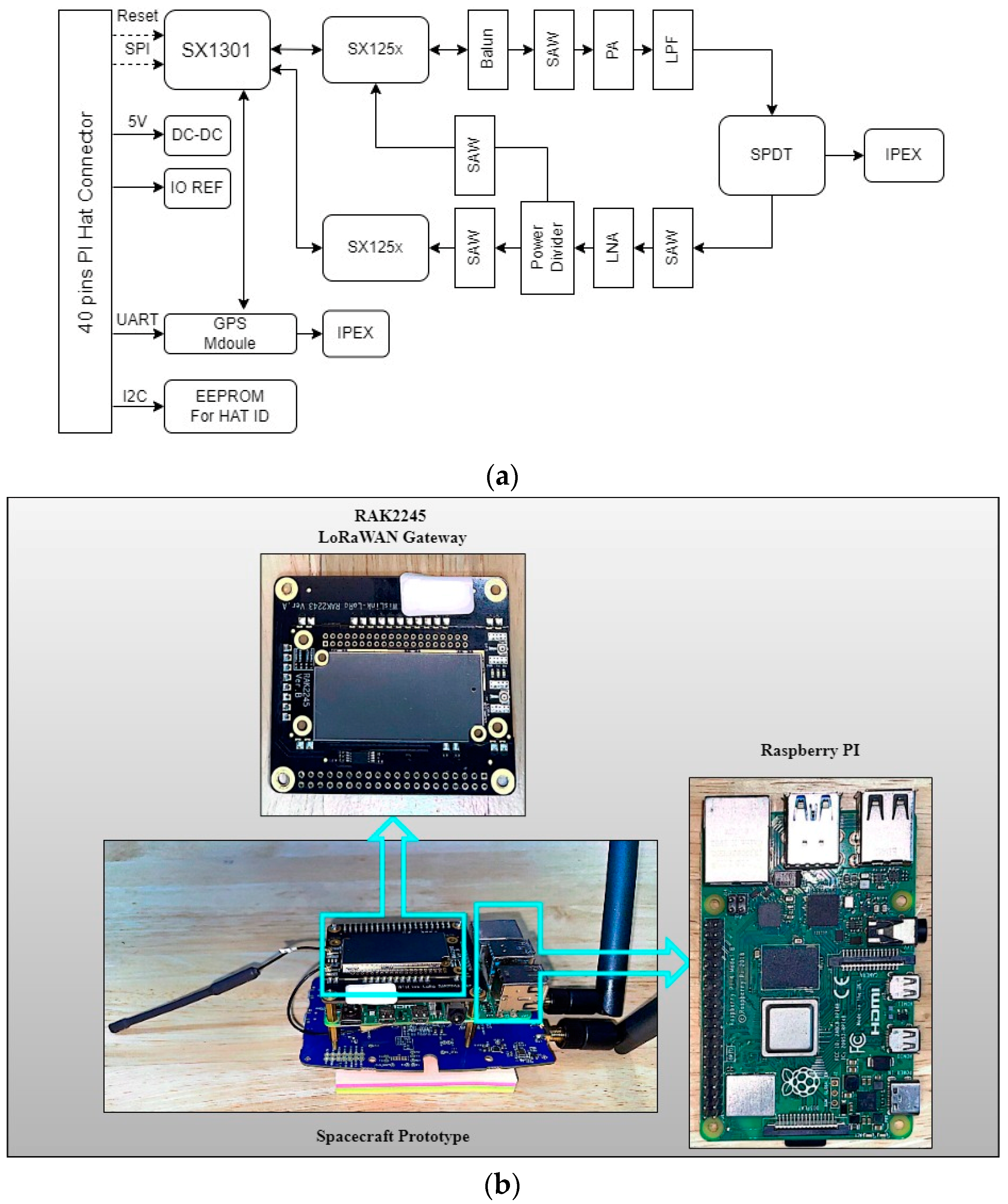
The RAK-Wireless Raspberry Pi HAT was utilized as the gateway in this experiment. The RAK-Wireless 2245 gateway is a Pi HAT which connects with Raspberry Pi over GPIO PINS. Raspberry Pi is derived from Linux Debian 32-bit Operating Software (OS). It is the best option as ARMv7 is the minimum system requirement to run the LoRaWAN gateway system. Any board computer with an ARMv7 processor can connect to the gateway over GPIO. The transceiver module consists of two LoRa chips (SX1301 and SX125x), which are coupled to form a gateway module. It has the potential to access up to 8 channels simultaneously, which in turn allows it to reach a greater number of end nodes. The gateway block diagram and module are shown in Figure 6 [26]. ADR is configured using Chirpstack network stack architecture [27].
Figure 6b demonstrates the RAK2245 LoRaWAN gateway stacked with the Raspberry Pi over GPIO pins, making the spacecraft prototype. The gateway does not need an external power supply as it receives power from the Raspberry Pi.
Table 4 shows typical transmit parameters of LoRaWAN gateway, highlighting the frequency range modulation schemes and threshold limits along with certain power levels. Meanwhile, Table 5 shows receive sensitivity levels at different spreading factors of the LoRaWAN gateway operation.
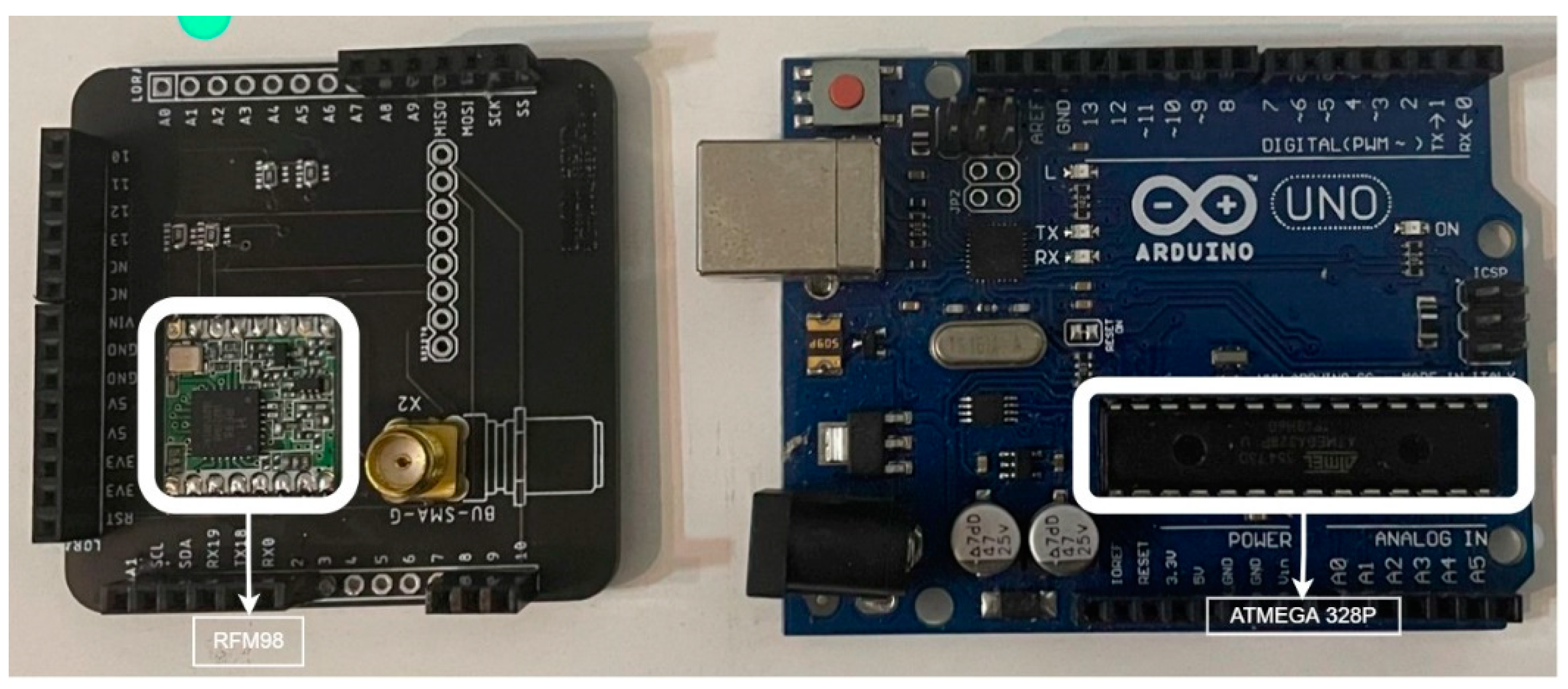
An end-user node comprises a LoRa transceiver with an SX1278 chip that operates in single-channel mode with the transmit power of 14 dBm. This configuration is limited to simply uplinking messages to the gateway. The ATMEGA A328P, which includes built-in flash memory, was used to create the LoRa transceiver. It is also in charge of managing the sensor data. The hardware for the end node is shown in Figure 7.
4.2.2. Experiment Performed
The signal is attenuated as per the slant range and path loss values shown in Table 3 to test the payload and end nodes modules. Various attenuators can be used to evaluate the output and practically determine incoming signal intensity. Here, fixed attenuators were used with a difference of 30 dB apart. The experiment was arranged in an enclosed, shielded box with an end node, and attenuators were introduced before the antenna to reduce the transmit signal strength. The received signal strength was compared as per path loss calculations. The experiment setups are shown in Figure 8.
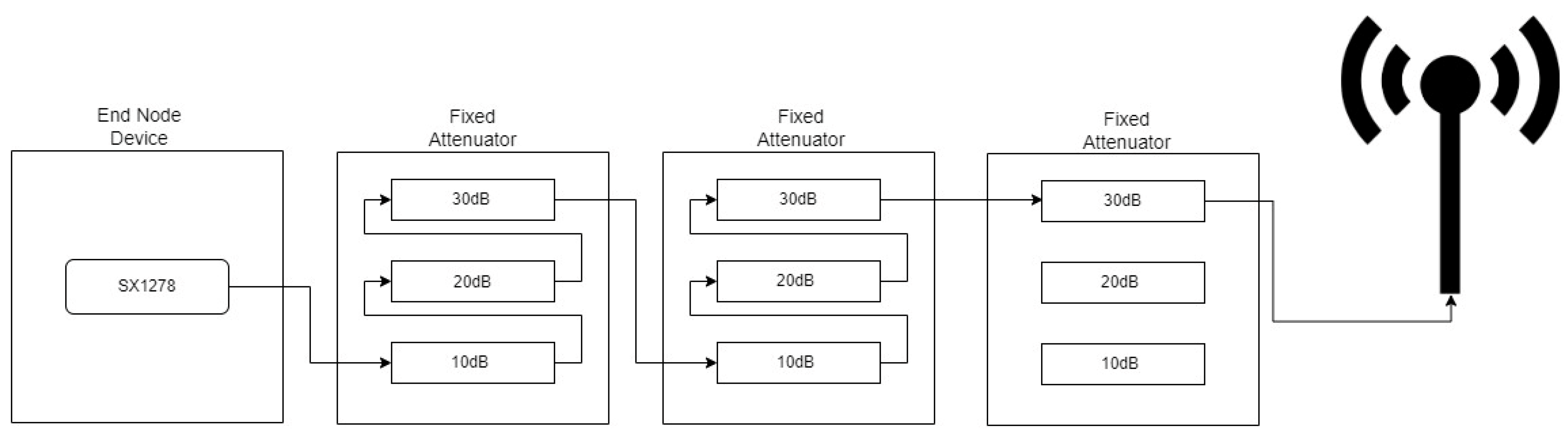
At first, the end node was enclosed in a box without a shield. It was observed that the signal was not lowering the level as per the attenuator. After troubleshooting, electromagnetic energy radiating from the antenna connector was detected. The box was then shielded with aluminum foil to create a Faraday cage-like environment. The attenuators were also covered with the same to prevent radiation escape. Figure 9 shows the schematic diagram representing this experimental setup. As per the slant range calculation, the maximum distance of 2705.3 km had a path loss of 148.8 dB at an angle of 0° elevation. Three attenuators were cascaded to achieve this distance. Each attenuator had 10–20–30 dB capabilities. They were connected in series to make one module with a maximum power of 60 dB, shown in Figure 9. The maximum value of 150 dB was achieved by combining the three modules.
5. Results
Experimental Results
Since LoRa modulation is used, the signal below the noise level can be detected, allowing the total receive power to be expressed as Equation (18).
where RSSI = Received Signal Strength Indicator,
SNR = Signal-to-Noise Ratio.
The result obtained at the gateway reception from the experiment is the RSSI and SNR values. Meanwhile, the total receive power is calculated using Equation (18) and the various attenuation levels shown in Table 6.
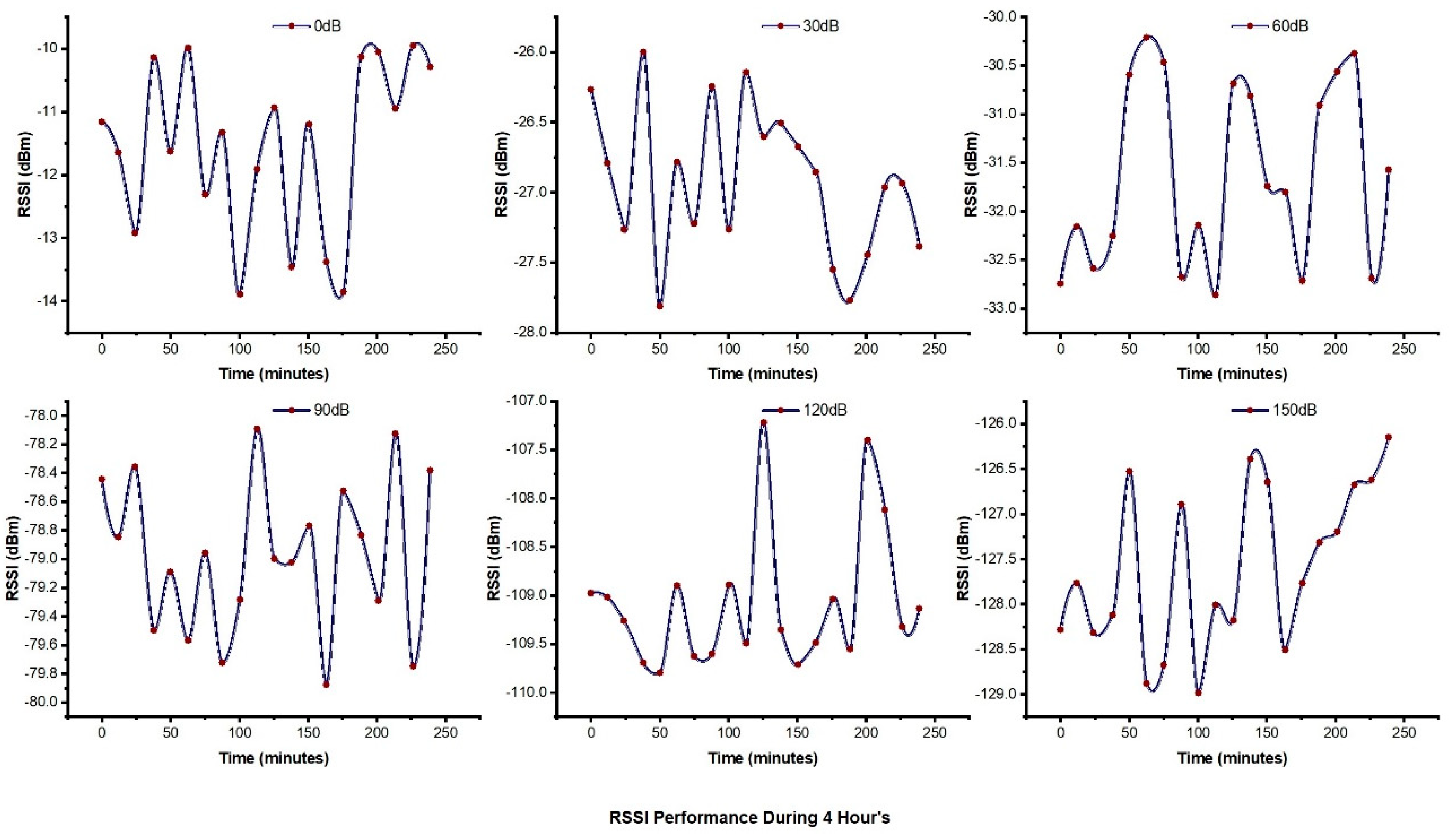
Each attenuation level was set for four hours to thoroughly monitor the received signal strength and signal-to-noise ratio. Figure 10 shows the signal RSSI behavior throughout the monitoring. Figure 11 shows the SNR results obtained by attenuating the signal level from 0–150 dB with a step of 30 dB, showing significant performance of the end node during the four-hour window. The result proves the stability of the LoRa signal-to-noise ratio.
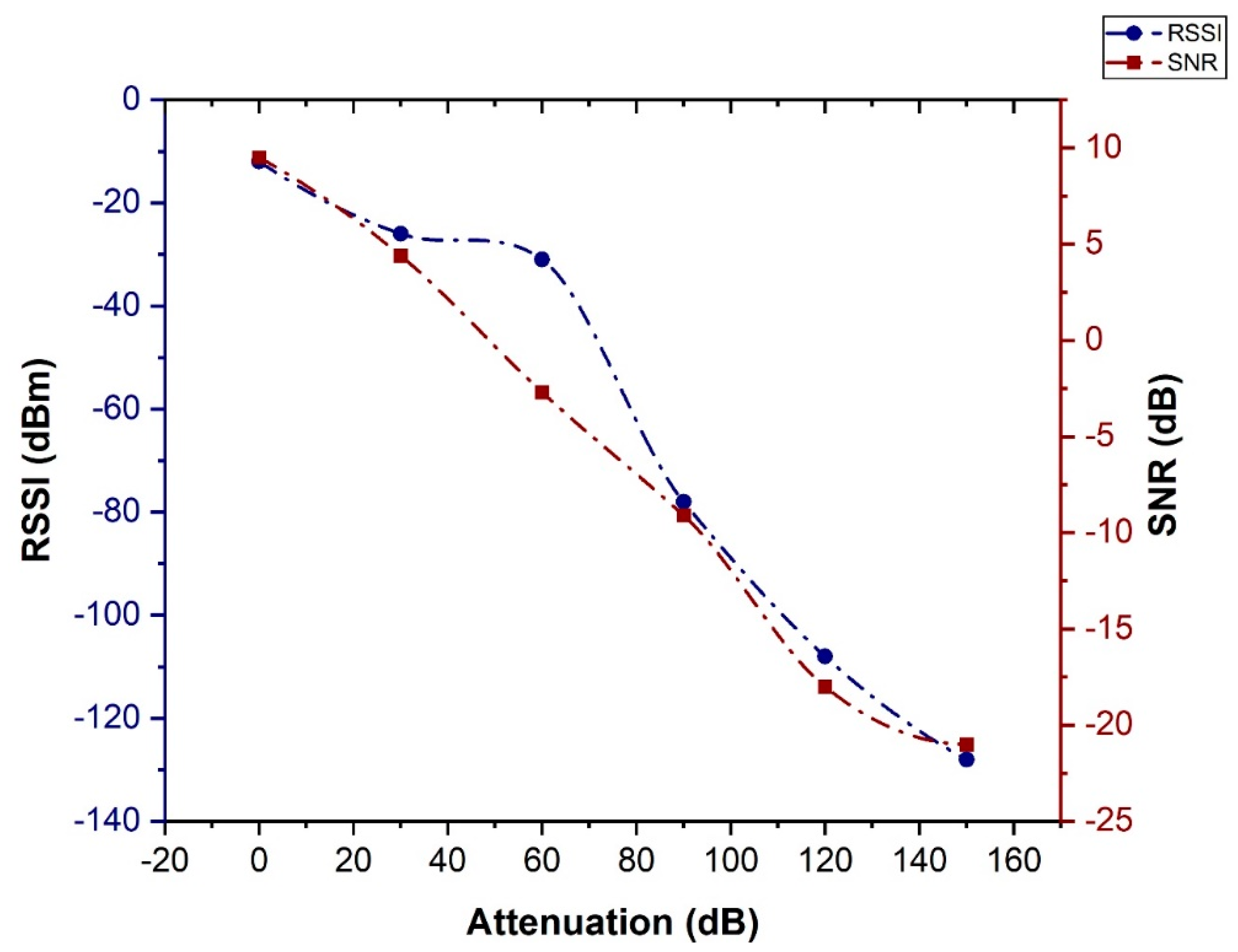
Trend analysis of RSSI and SNR performance Figure 12 shows the correlation of RSSI and SNR concerning the attenuation level to simulate the path loss of spacecraft at an altitude of 550 km.
As shown in the above experiment, it is observed that we received the signal at 150 dB, which is the maximum distance of our slant range. This confirms that the spacecraft at a minimum look angle will be able to transmit data.
Notably, with a transmit power of only 14 dBm, signals can travel great distances without fading or being interrupted by external factors compromising signal integrity. LoRa’s Signal-to-Noise Ratio (SNR) is an additional crucial aspect contributing to the signal’s excessive range. Even at an SNR of −21 dB, which indicates that the signal is buried by a factor of 20 or more below the noise floor, the receiver may still identify the signal. Moreover, signal performance shows sudden fluctuation whenever the device temperature increases. Fluctuation is noticed on both RSSI and SNR performance which in turns degraded the reception. ADR enables dynamic signal reception, which is a practical option for fast-moving satellites to mitigate the Doppler effect. In addition, during the signal attenuation experiment, it was discovered that the end device PCB circuit was leaking signal. In the light of this research, it is essential to note that when building a chipboard for an end product, shielding and proper circuit design should be considered, as well as all feasible angles to prevent signal leakage. Additionally, it is important to note that the inclusion of ADR in the system makes it more adaptable.
Experimental results showed significant LoRa signal performance even at the lowest attenuated level. Under the line of results, it is proof that sensor devices, when transmitting a signal using a LoRa transmitter, can communicate to the LoRaWAN gateway even with a maximum distance of 2705.3 km (Table 3). As per observed results, it is clear that the LoRaWAN gateway can use as a payload for the CubeSats and is a comparatively cheaper solution while creating the system design of LoRaWAN sensor networks.
6. Conclusions
This paper proposes assessing the LoRaWAN CubeSat signal with an Adaptive Data Rate (ADR) while carrying the LoRaWAN gateway in the payload subsystem. It demonstrated a signal from nodes to Direct-to-Satellite (DtS) with a transmit power of 14 dBm. Path loss link margin was calculated as stated in the literature and then verified by adding a fixed attenuator of up to 150 dB. The system proved and satisfied the signal transmitted from the node to the LoRaWAN satellite gateway at worst case scenario: 5° of elevation angle, roughly 2205.9 km, was successfully received by the gateway.
Received signal strength and Signal-to-Noise Ratio (SNR) were observed for 4 h to identify any misbehavior during the window. The signal was observed to be stable, and the LoRaWAN gateway could receive signals per the calculated distance with a minimum transmit power. The results showed that the LoRaWAN gateway can receive a direct signal from the nodes. The gateway can be used in a CubeSat as a communication subsystem while deploying a sensor network of small satellites. The findings also demonstrated that spacecraft equipped with a LoRaWAN gateway and ADR can properly receive uplink messages from ground nodes independent of Doppler shift. However, in the real time use of LoRaWAN gateway, far field should have influence on the system which has to be taken into account.
As indicated, this study shows the single-module possibilities of LoRaWAN. Compared to TinyGS architecture, the Kitsune mission, and the Birds mission, which exclusively employ LoRa transmitters, this research presents the LoRaWAN-enabled communication subsystem for the CubeSats missions as a low-cost, low-power approach for creating sensor networks.
Additional work is needed for future investigation on delivering nodes data received by the gateway on LEO to the ground station. The investigation of achieving nodes data on the spacecraft onboard board computer with minimum computing power when the ground station is not visible is also needed.
Author Contributions
Formal analysis, S.Z.A.M.; Investigation, S.Z.A.M.; Supervision, A.M.A.; Writing—original draft, S.Z.A.M.; Writing—review and editing, A.M.A. and S.Z. All authors have read and agreed to the published version of the manuscript.
Funding
This research was funded by the Ministry of Higher Education Malaysia on Fundamental Research Grant Scheme with Project Code: FRGS/1/2020/TK0/USM/03/8, and the APC was funded by Universiti Sains Malaysia.
Data Availability Statement
The data presented in this study are available on request from the corresponding author.
Acknowledgments
The authors would like to thank all who have directly or indirectly provided assistance to support this project.
Conflicts of Interest
The authors declare no conflict of interest.
References
- Cao, C.; Zhai, S. The influence of LEO satellite Doppler effect on LoRa modulation and its solutio. J. Phys. Conf. Ser. 2021, 1883, 12071. [Google Scholar] [CrossRef]
- Prokopyev, V.Y.; Bakanov, S.S.; Bodrov, V.K.; Chernodarov, E.N.; A Doroshkin, A.; Gorev, V.N.; Kolesnikova, A.Y.; Kozlov, A.S.; Kus, O.N.; Melkov, A.V.; et al. NORBY CubeSat nanosatellite: Design challenges and the first flight data. J. Phys. Conf. Ser. 2021, 1867, 012038. [Google Scholar] [CrossRef]
- Lepcha, P.; Malmadayalage, T.D.; Örger, N.C.; Purio, M.A.; Duran, F.; Kishimoto, M.; El-Megharbel, H.A.; Cho, M. Assessing the Capacity and Coverage of Satellite IoT for Developing Countries Using a CubeSat. Appl. Sci. 2022, 12, 8623. [Google Scholar] [CrossRef]
- Gregor, T. Calhoun: The NPS Institutional Archive DSpace Repository Next Generation of CubeSat Orbital Mesh Networking Assets, Challenges and Architectures-LORA Replication with Software Defined Radios. Available online: http://hdl.handle.net/10945/70442 (accessed on 3 December 2022).
- Developer Semtech LoRa, LoRa Developer Portal—Implementing Adaptive Data Rate (ADR). Available online: https://lora-developers.semtech.com/documentation/tech-papers-and-guides/implementing-adaptive-data-rate-adr/implementing-adaptive-data-rate/ (accessed on 3 December 2022).
- Techavijit, P.; Sukchalerm, P.; Wongphuangfuthaworn, N.; Plodpai, A.; Manuthasna, S.; Chivapreecha, S. Internet Network in Space for Small Satellites: Concept and Experiments. Sensors Mater. 2018, 30, 2295–2311. [Google Scholar] [CrossRef] [Green Version]
- Trasviña-Moreno, C.A.; Blasco, R.; Marco, Á.; Casas, R.; Trasviña-Castro, A. Unmanned Aerial Vehicle Based Wireless Sensor Network for Marine-Coastal Environment Monitoring. Sensors 2017, 17, 460. [Google Scholar] [CrossRef] [PubMed]
- Neumann, P.; Montavont, J.; Noel, T. Indoor deployment of low-power wide area networks (LPWAN): A LoRaWAN case study. In Proceedings of the 2016 IEEE 12th international conference on wireless and mobile computing, networking and communications (WiMob), New York, NY, USA, 17–19 October 2016; pp. 1–8. [Google Scholar] [CrossRef]
- Parri, L.; Parrino, S.; Peruzzi, G.; Pozzebon, A. Low Power Wide Area Networks (LPWAN) at Sea: Performance Analysis of Offshore Data Transmission by Means of LoRaWAN Connectivity for Marine Monitoring Applications. Sensors 2019, 19, 3239. [Google Scholar] [CrossRef] [PubMed] [Green Version]
- Chen, Y.; Zhang, M.; Li, X.; Che, T.; Jin, R.; Guo, J.; Yang, W.; An, B.; Nie, X. Satellite-Enabled Internet of Remote Things Network Transmits Field Data from the Most Remote Areas of the Tibetan Plateau. Sensors 2022, 22, 3713. [Google Scholar] [CrossRef] [PubMed]
- Kufakunesu, R.; Hancke, G.; Abu-Mahfouz, A. A Fuzzy-Logic Based Adaptive Data Rate Scheme for Energy-Efficient LoRaWAN Communication. J. Sens. Actuator Netw. 2022, 11, 65. [Google Scholar] [CrossRef]
- TinyGS Website, TinyGS. Available online: https://tinygs.com/satellites (accessed on 3 December 2022).
- Morelli, G.; Parissenti, G.; Navoni, R.; Ambroggi, D.; Hofman, J.; Pavia, M.; Gabetta, G.; Ampolo, S.; Surel, Y.; Lavagna, M.; et al. Fees Flexible Experimental Embedded Satellite Icubesat Politecnico Di Milano. Available online: https://icubesat.files.wordpress.com/2019/05/b.1.3.201905241518-morelli.pdf (accessed on 1 December 2022).
- FossaSat-2E1 Satellite—TinyGS. Available online: https://tinygs.com/satellite/FossaSat-2E1 (accessed on 3 May 2022).
- Polytech Universe-1, Polytech_Universe. Available online: https://tinygs.com/satellite/Polytech_Universe-1 (accessed on 23 December 2022).
- Lepcha, P.; Kim, S.; Masui, H.; Cho, M. Application of Small Satellites for Low-Cost Remote Data Collection Using LoRa Transmitters. Trans. Jpn. Soc. Aeronaut. Space Sci. Aerosp. Technol. Jpn. 2021, 19, 224–230. [Google Scholar] [CrossRef]
- Mroue, H.; Nasser, A.; Hamrioui, S.; Parrein, B.; Motta-Cruz, E.; Rouyer, G. MAC layer-based evaluation of IoT technologies: LoRa, SigFox and NB-IoT. In Proceedings of the 2018 IEEE Middle East and North Africa Communications Conference (MENACOMM), Jounieh, Lebanon, 18–20 April 2018; pp. 1–5. [Google Scholar] [CrossRef]
- Nashiruddin, M.I.; Yusri, A. SigFox Network Planning for Smart Metering Based on Internet of Things for Dense Urban Scenario. In Proceedings of the 2020 8th International Conference on Information and Communication Technology (ICoICT), Yogyakarta, Indonesia, 26 June 2020. [Google Scholar]
- Alobaidy, H.A.H.; Mandeep, J.S.; Nordin, R.; Abdullah, N.F. A Review on ZigBee Based WSNs: Concepts, Infrastructure, Applications, and Challenges. Int. J. Electr. Electron. Eng. Telecommun. 2020, 9, 189–198. [Google Scholar] [CrossRef]
- Sturdivant, R.L.; Yeh, J.; Stambaugh, M.; Zahnd, A.; Villareal, N.; Vetter, C.K.; Rohweller, J.D.; Martinez, J.F.; Ishii, J.M.; Brown, R.A.; et al. IoT enabled pico-hydro electric power with satellite back haul for remote himalayan villages. In Proceedings of the 2018 IEEE Topical Workshop on Internet of Space (TWIOS), Anaheim, CA, USA, 14–17 January 2018; pp. 5–8. [Google Scholar] [CrossRef]
- Routray, S.K.; Javali, A.; Sahoo, A.; Sharmila, K.P.; Anand, S. Military Applications of Satellite Based IoT. In Proceedings of the 2020 Third International Conference on Smart Systems and Inventive Technology (ICSSIT), Tirunelveli, India, 20–22 August 2020; pp. 122–127. [Google Scholar] [CrossRef]
- Conti, M.; Andrenacci, S.; Maturo, N.; Chatzinotas, S.; Vanelli-Coralli, A. Doppler Impact Analysis for NB-IoT and Satellite Systems Integration. In Proceedings of the ICC 2020 IEEE International Conference on Communications (ICC), Dublin, Ireland, 7–11 June 2020; pp. 1–7. [Google Scholar] [CrossRef]
- Cakaj, S.; Kamo, B.; Koliçi, V.; Shurdi, O. The Range and Horizon Plane Simulation for Ground Stations of Low Earth Orbiting (LEO) Satellites. Int. J. Commun. Netw. Syst. Sci. 2011, 4, 585–589. [Google Scholar] [CrossRef]
- Eriksson, J.; Andersen, J.S. Investigating the Practical Performance of the LoRaWAN Technology. Available online: www.liu.se (accessed on 1 December 2022).
- Cakaj, S.; Kamo, B.; Lala, A.; Rakipi, A. The Coverage Analysis for Low Earth Orbiting Satellites at Low Elevation. 2014. Available online: www.ijacsa.thesai.org (accessed on 12 September 2022).
- RAKwireless, RAK2245 Pi HAT WisLink LPWAN Concentrator Datasheet, Documentation Center. 2022. Available online: https://docs.rakwireless.com/Product-Categories/WisLink/RAK2245-Pi-HAT/Datasheet/#overview (accessed on 1 November 2022).
- Chirpstack Network, Chirpstack Documentation. Available online: https://www.chirpstack.io/docs/v3-documentation.html (accessed on 27 December 2022).
- Hope RF RFM96, RFM96,97,98 Product Datasheet. Available online: https://www.hoperf.com/data/upload/portal/20190801/RFM98W-V2.0.pdf (accessed on 30 December 2022).
- Arduino Uno R3, Arduino® UNO R3—Product Datasheet. Available online: https://docs.arduino.cc/resources/datasheets/A000066-datasheet.pdf (accessed on 30 December 2022).
Figure 1.
Direct-to-Satellite (DtS) vs ground data relay architecture.

Figure 2.
Cartesian coordinates geometry diagram of ground observer.

Figure 3.
Spherical geometry of Earth station and spacecraft sub-points.

Figure 4.
Slant range angle geometrical representation.

Figure 5.
Relation between elevation and slant range distance at different levels by path loss calculation obtained from Table 3.
Figure 5.
Relation between elevation and slant range distance at different levels by path loss calculation obtained from Table 3.

Figure 6.
(a) Block diagram [26] and (b) module of LoRaWAN gateway together with the Raspberry Pi used in this study.
Figure 6.
(a) Block diagram [26] and (b) module of LoRaWAN gateway together with the Raspberry Pi used in this study.

Figure 7.
The hardware of end nodes setup with RFM 98 LoRa module and ATMEGA A328P Arduino Uno microcontroller board [28,29].

Figure 8.
Shielded box to create a Faraday cage-like environment to overcome signal leakage.

Figure 9.
Block diagram of attenuators used to simulate path loss in Figure 8.
Figure 9.
Block diagram of attenuators used to simulate path loss in Figure 8.

Figure 10.
Observed Received Signal Strength Indicator (RSSI) at various attenuation levels during the four−hour window.
Figure 10.
Observed Received Signal Strength Indicator (RSSI) at various attenuation levels during the four−hour window.

Figure 11.
Results of Signal−to−Noise Ratio (SNR) during the four-hour window.

Figure 12.
Relationship of RSSI and SNR at 0−150 dB attenuation levels with a step of 30 dB.


Table 1.
Comparing this research with past research mentioning network topology and message response using LoRa.
Table 1.
Comparing this research with past research mentioning network topology and message response using LoRa.
| Ongoing Mission/Research | Maximum Recorded Distance (km) | Minimum Elevation (degree) | RSSI (dBm) | SNR (dB) | Gateway | Data Rate | Topology |
|---|---|---|---|---|---|---|---|
| NORBY [2] | 2622 | 0.88 | −111.75 | −7.75 | Single Channel | Auto-Tune | Echo Response |
| Fees [13] | 2554 | 1.09 | −132.5 | −9.5 | Single Channel | Auto-Tune | Echo Response |
| Fossasat-2E1 [14] | 2279 | 3.53 | −133.75 | −13.75 | Single Channel | Auto-Tune | Echo Response |
| Polytect_Universe-1 [15] | 1339 | 16.61 | −130 | −11.5 | Single Channel | Auto-Tune | Echo Response |
| Pooja Lepcha et al. [16] | 1439.8 | 10 | −141.6 | - | Single Channel | Fixed | Send/Receive |
| This Research | 2703 | 0 | −128 | −21 | 8 Channels | Adaptive Data Rate | Star Topology |
Table 2.
Comparison of different IoT Technologies.
| IoT Technology | Range | Through-Put | Power Consumption | Spectrum | Modulation |
|---|---|---|---|---|---|
| SigFox | 3–50 km | 100 bps | Low | 868,915 MHz | BPSK, GFSK |
| Zigbee | 30–50 m | 10–100 Kbps | Low | 868,915 MHz 2.4 GHz | DBPSK, OQPSK |
| NB-IoT | 1–10 km | 200 bps | Low | 450 MHz–2.1 GHz | QPSK, OFDM, SC-FDMA |
| LoRa | 2–20 km | 10–50 Kbps | Low | 169 MHz, 433 MHz, 868 MHz, 915 MHz | LoRa, FSK, GFSK |
Table 3.
Path loss calculation with the look angle and distance measured using Equations (11) and (17).
Table 3.
Path loss calculation with the look angle and distance measured using Equations (11) and (17).
| Elevation (deg) | Slant Range (km) | FSPL (dB) |
|---|---|---|
| 0° | 2705.3 | 148.8 |
| 5° | 2205.9 | 147.0 |
| 10° | 1815.7 | 145.4 |
| 20° | 1293.8 | 142.4 |
| 30° | 992.9 | 140.1 |
| 40° | 812.1 | 138.4 |
| 50° | 698.9 | 137.1 |
| 60° | 626.9 | 136.1 |
| 70° | 582.3 | 135.5 |
| 80° | 557.8 | 135.4 |
| 90° | 550.0 | 135.0 |
Table 4.
Frequency and modulation hardware parameters of the LoRaWAN gateway used in an experiment.
| Parameter | Condition | Min | Max |
|---|---|---|---|
| Frequency | 433 MHz | 435 MHz | |
| Modulation | FSK/LoRaTM | ||
| Tx Power vs. Temperature | Power Level Setting:20 | −3 kHz | +3 kHz |
| Tx Power vs. Temperature | −5 dBm | +5 dBm | |
| TX Power Variation | −1.5 dBm | +1.5 dBm |
Table 5.
Receive sensitivity threshold of the LoRaWAN Gateway used in an experiment.
| Bandwidth (kHz) | Spreading Factor | Sensitivity (dBm) |
|---|---|---|
| 125 | 12 | −139 |
| 125 | 7 | −126 |
| 250 | 12 | −136 |
| 250 | 7 | −123 |
| 500 | 12 | −134 |
| 500 | 7 | −120 |
Table 6.
Results received at the gateway side at different attenuation levels.
| Attenuation | 0 dB | 30 dB | 60 dB | 90 dB | 120 dB | 150 dB |
|---|---|---|---|---|---|---|
| RSSI (dBm) | −12.0 | −26.0 | −78.0 | −108.0 | −121 | −128 |
| SNR (dB) | 9.5 | 4.4 | −2.7 | −9.1 | −18 | −21 |
| (dBm) | −2.5 | −21.6 | −80.7 | −117.1 | −139 | −149 |
Disclaimer/Publisher’s Note: The statements, opinions and data contained in all publications are solely those of the individual author(s) and contributor(s) and not of MDPI and/or the editor(s). MDPI and/or the editor(s) disclaim responsibility for any injury to people or property resulting from any ideas, methods, instructions or products referred to in the content. |
© 2023 by the authors. Licensee MDPI, Basel, Switzerland. This article is an open access article distributed under the terms and conditions of the Creative Commons Attribution (CC BY) license (https://creativecommons.org/licenses/by/4.0/).
Share and Cite
MDPI and ACS Style
Mehdi, S.Z.A.; Mohd Ali, A.; Zulkifli, S. LoRaWAN CubeSat with an Adaptive Data Rate: An Experimental Analysis of Path Loss Link Margin. Aerospace 2023, 10, 53. https://doi.org/10.3390/aerospace10010053
AMA Style
Mehdi SZA, Mohd Ali A, Zulkifli S. LoRaWAN CubeSat with an Adaptive Data Rate: An Experimental Analysis of Path Loss Link Margin. Aerospace. 2023; 10(1):53. https://doi.org/10.3390/aerospace10010053
Chicago/Turabian StyleMehdi, Syed Zafar Abbas, Aiffah Mohd Ali, and Safiah Zulkifli. 2023. "LoRaWAN CubeSat with an Adaptive Data Rate: An Experimental Analysis of Path Loss Link Margin" Aerospace 10, no. 1: 53. https://doi.org/10.3390/aerospace10010053
Note that from the first issue of 2016, this journal uses article numbers instead of page numbers. See further details here.