Article

Quartz Crystal Microbalances for Space: Design and Testing of a 3D Printed Quasi-Kinematic Support

1
Mechanical Department, Polytechnic University of Milan, via La Masa 1, 20156 Milano, Italy
2
Rebel Dynamics, via Carlo Porta 38, Cesana Brianza, 23861 Lecco, Italy
3
National Institute for Astrophysics INAF-IAPS, via del Fosso del Cavaliere 100, 00133 Roma, Italy
4
Institute of Atmospheric Pollution Research, National Research Council of Italy, 00015 Monterotondo, Italy
*
Author to whom correspondence should be addressed.
Aerospace 2023, 10(1), 42; https://doi.org/10.3390/aerospace10010042
Submission received: 30 October 2022 / Revised: 20 December 2022 / Accepted: 29 December 2022 / Published: 2 January 2023
(This article belongs to the Special Issue Advanced Small Satellite Technology)

Abstract

:
Outgassing or thruster’s generated contaminants are critical for optical surfaces and optical payloads because scientific measurements and, in general, the performances can be degraded or jeopardized by uncontrolled contamination. This is a well-known issue in space technology that is demonstrated by the growing usage of quartz crystal microbalances as a solution for measuring material outgassing properties data and characterizing the on-orbit contamination environment. Operation in space requires compatibility with critical requirements, especially the mechanical and thermal environments to be faced throughout the mission. This work provides the design of a holding structure based on 3D printing technology conceived to meet the environmental characteristics of space application, and in particular, to face harsh mechanical and thermal environments. A kinematic mounting has been conceived to grant compatibility with a large temperature range, and it has been designed by finite element methods to overcome loading during the launch phases and cope with a temperature working range down to cryogenic temperatures. Qualification in such environments has been performed on a mockup by testing a prototype of the holding assembly between −110 °C and 110 °C and allowing verification of the mechanical resistance and stability of the electrical contacts for the embedded heater and sensor in that temperature range. Moreover, mechanical testing in a random environment characterized by an RMS acceleration level of 500 m/s2 and excitation frequency from 20 to 2000 Hz was successfully performed. The testing activity allowed for validation of the proposed design and opened the road to the possible implementation of the proposed design for future flight opportunities, also onboard micro or nanosatellites. Moreover, exploiting the manufacturing technology, the proposed design can implement an easy assembling and mounting of the holding system. At the same time, 3D printing provides a cost-effective solution even for small series production for ground applications, like monitoring the contaminants in thermo-vacuum chambers or clean rooms, or depositions chambers.

1. Introduction

Additive Manufacturing (AM) is transforming aerospace and space industries, offering several advantages compared to conventional manufacturing techniques. Indeed, the ability of the AM to fabricate freeform design or develop structural parts meeting specific, unconventional, and challenging requirements, especially for such components that have very complex hollow structures, is very attractive for the space industry [1,2,3,4]. Design for AM aims for a substantial reduction in manufacturing time, cost, and material wastage and, at the same time, a considerable reduction in the complexity of the integration phases. Indeed, the aerospace industry extensively uses AM for prototyping, testing, repairing, and tooling, and besides the usage of plastics and thermoplastics [5,6], space research has been pushing in recent years the development of high-performance metallic materials or structural parts made by selective laser melting and electron beam technologies [7,8,9,10,11,12]. Indeed, there are still some limitations of the additive technologies in the space field related to the process tuning, achievable dimensional accuracy, repeatability, and stability of the mechanical properties [13,14,15]. Depending on the design requirements and the performed design, these can limit the achievement of the expected improvements or lead to unfeasible designs or solutions. Thus, many efforts are performed by the scientific community to deepen the knowledge about the manufacturing processes, minimize these critical issues and standardize AM [16,17,18,19,20].
This work investigates the design of a 3D-printed holder for a quartz crystal microbalance developed to operate in space [21]. The quartz crystal microbalance provides the measurement of the deposition or condensation rate of dust or volatile condensable materials on an oscillating quartz crystal. Often, a double crystal configuration is used since the difference in oscillation frequency between a reference crystal and the measurement one, on which the volatile condensable materials are deposited, should change only because of the condensed mass, allowing for the deposition rate measurement [8]. The double crystal configuration is required mostly to compensate for the temperature effect on the sensor output. However, measuring the beating frequency also allows for dramatically reducing the frequency range to be measured. The single-crystal configuration, nevertheless, can be considered as well if the temperature of the microbalance can be accurately measured. In this case, proper calibration of the temperature dependence of the microbalance and accurate measurement of the crystal temperature allow simplifying the overall instrument, providing a valid alternative for the most common double-crystal microbalances.
QCMs have been used to monitor outgassing and space contamination onboard different space missions [22]. Up to date, all the QCMs currently used for space are mainly provided by US companies, like QCM ResearchCompany and CrystalTeck Corp, which gained flight heritage onboard different NASA missions. More recently, the Japanese company: MEISEIElectric Co provided the market with a qualified sensor for space. Lately, space-designed QCMs have been designed for the HERA mission by ESA [23], developing a double-crystal sensor to be mounted onboard the Milani satellite.
The major advantage of the QCM layout used in this study is the possibility to directly heat the crystal during thermo-gravimetric analyses and measure the electrode’s temperature by deposited embedded thin-film resistors, therefore improving the accuracy of the performed measurements. One general requirement for the development of microbalances for space is the design of a proper supporting structure. The latter should grant for the proper constraining of the crystals to achieve acceptable stresses in the expected mechanical environments and, at the same time, allow for its thermal expansion in the full temperature range of the mission.
Such a kind of mounting requirement is also typical for optical elements that need to operate in space and requires the development of quasi-kinematic supporting structures [24]. In the case study, the design was performed by exploiting 3D printing by stereolithography because the technology allows for achieving high spatial resolution and complex shapes. Moreover, the proposed, designed solution assures all the required functionalities of the microbalance, i.e., it provides the required electrical contacts and allows measurement of the crystal oscillating frequency, temperature, and heating during the regeneration phases. Moreover, the developed design would provide an easy replacement of the crystals and a cost-effective solution, compared to commercial quartz crystal microbalances for space, even for small series production.

2. Materials and Methods

The support shall keep the quartz crystal in position in any phase of its working. In order to do so, the support shall provide a symmetrical mounting with three elements to keep the crystal. A scheme showing the concept of the conceived mounting is provided in Figure 1a. The elements should ensure low radial stiffnesses to cope with the thermally generated differential expansions and large enough axial and tangential (i.e., perpendicular to the Figure 1a plane) stiffnesses to assure a lower resonance frequency above those of the main modes of the structure on which the QCM is mounted.
Spherical pads were designed as crystal interfaces to avoid extended contacts that would lead to slidings under thermal cycling while still controlling the pressure at the contact. The holding pads must ensure stable mechanical but also electrical connections. Design requirements were defined considering typical scenarios for space applications [21] and the experience gained in other projects [25]:
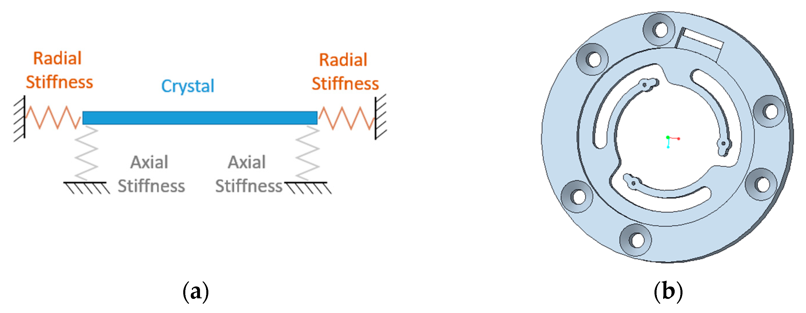
  • Radial stiffness for each holder element should be lower than 1.2 N/mm, a value identified to reduce thermal stresses on the crystal in the temperature range between −190 °C and 150 °C with a CTE mismatch between holder and crystal not exceeding 30 ppm/K;
  • A design load given as a quasi-static acceleration of one hundred times the Earth’s gravitational acceleration was used;
  • The lowest resonance frequency must be larger than 150 Hz, a general constraint to avoid unwanted forcing on the mechanical system by mounting system resonances.
As a functional requirement, the holder must provide electrical connections to the crystal electrodes and the deposited resistors that are used as heaters and thermometers for thermogravimetric analyses [26].
After a preliminary evaluation of the available technology, either considering plastics or metallic materials, the design focused on two different materials, i.e., the FLHTAM02 resin (provided by FoamLab) and the ULTEM 9085 (high-strength plastic by Starsys). The latter has also been recently studied for some space applications [27,28]. It has to be noticed that plastics were chosen instead of metals as a baseline for the holder design because the required holding structure should be electrically insulated from the crystals to avoid shortcircuits and ensure the required electrical connections for the embedded heater and temperature sensor and oscillate the crystals themselves. Moreover, the comparison between selected materials evidenced similar physical and thermal characteristics and a larger mechanical resistance of the ULTEM 9085 material, providing bending limit stress at 134 MPa instead of 97.2 MPa. Despite that, the FLHTAM02 was chosen because the achievable printing resolution was five times smaller, therefore allowing for better accuracy of the achievable geometry. The latter characteristic is a key point in the design of such a compliant structure because any large deviation from the nominal size would jeopardize the obtained stiffness, therefore invalidating the intended result.
Moreover, to minimize the radial size of the holder, the conceived quasi-kinematic mounting was developed by designing curved supports, as reported in Figure 1b, where a single disk geometry is shown. The designed supports are flexible in the radial direction, allowing almost free thermal expansion of the crystal in the thermal environment but at the same time providing axial stiffness. The latter characteristic allows for mechanical stiffness and strength in the harsh vibration environment, as generally required for space applications. A detailed design of the single disk was already performed using an FE (Finite Element) approach [29], allowing successful validation of the design requirements. The numerical analyses proved that the radial and axial stiffnesses are compliant with the design requirements, providing stiffnesses at about 0.88 N/mm and 1.25 N/mm for the radial and axial directions, respectively. Moreover, modal and quasi-static analyses were performed as well, testifying to the mechanical resistance of the single disk in the expected environment.
A new FE model comprising two crystals and related quasi-kinematic mounting was designed and tested with static, modal, and thermoelastic analyses aiming to assess the validity of the proposed design. A description of the model and obtained numerical results are reported and discussed.

3. Detailed Design

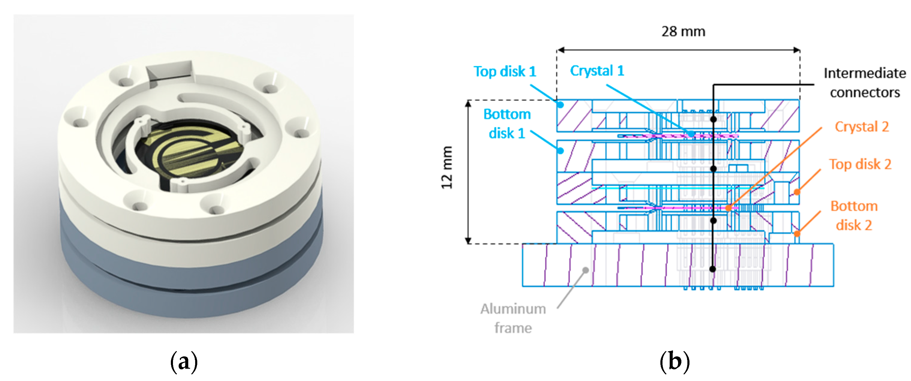
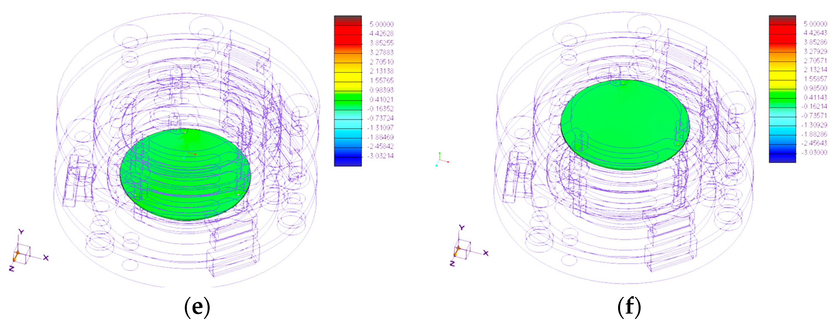
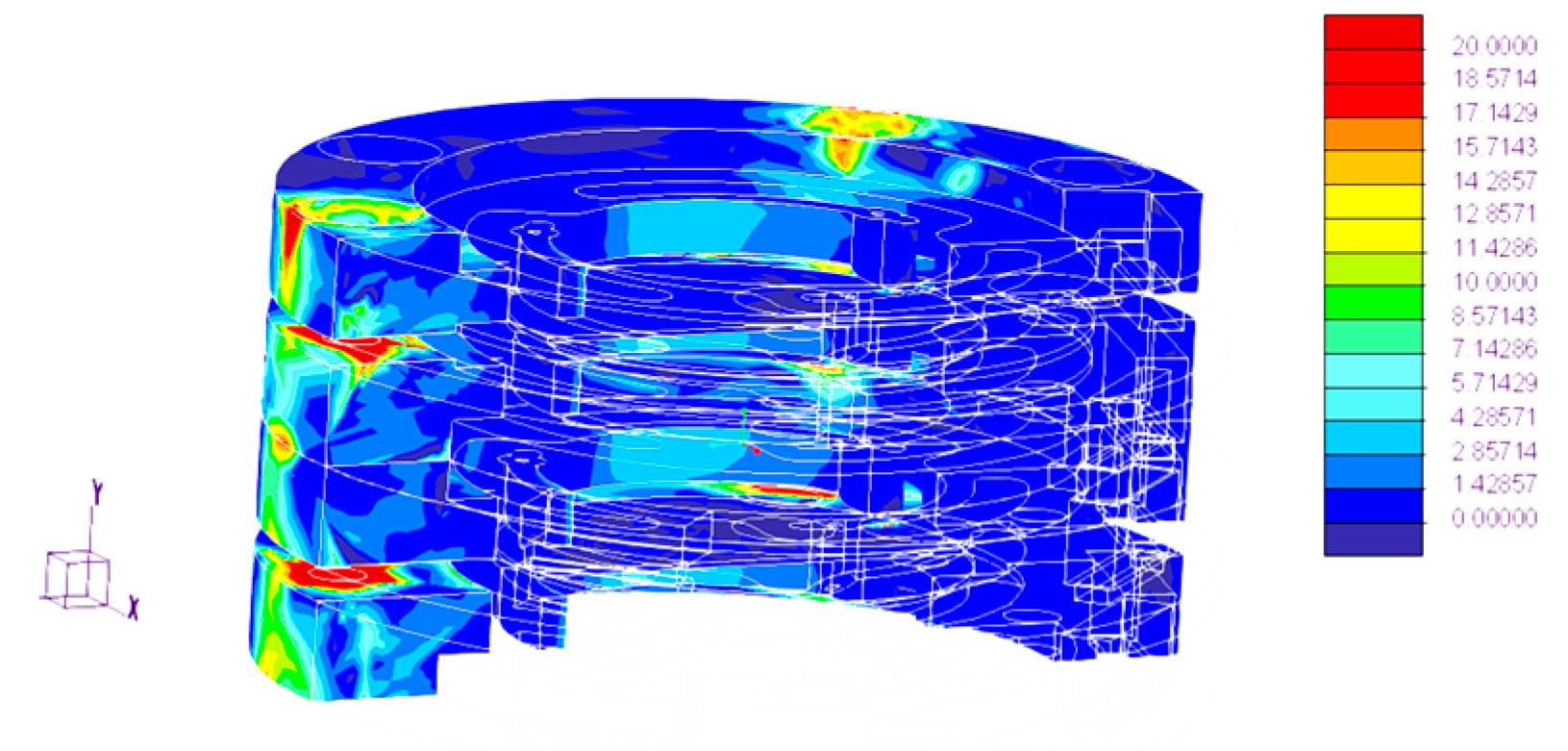
3.1. Model Description
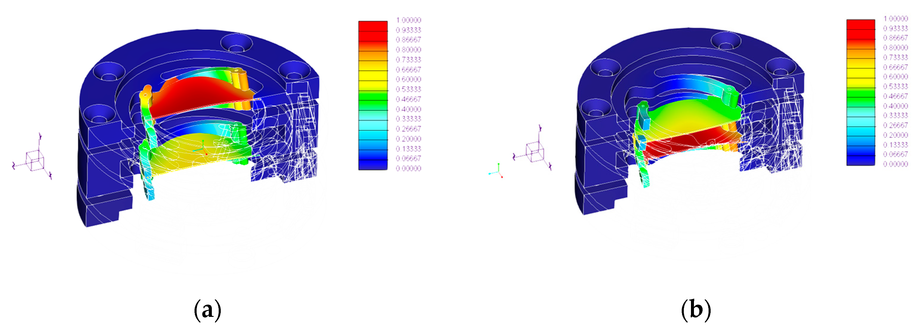
The microbalance in a double-crystal configuration comprises two supports, one for each crystal, whose geometry is shown in Figure 2a. The design improved the compactness of the quasi-kinematic mounting, limiting the overall height to 12 mm and the radial size to a circumference of 28 mm diameter. The total mass of the structure, considering screws and threaded connections, is just about 10 g. Moreover, a simple procedure for the crystal mounting and dismounting can be achieved by screwing or unscrewing the holders from the overall element, also ensuring direct access to the electrodes while handling the crystals. Indeed, each support has grooves to host electrical wires, intermediate connectors (pin header and female header connectors by GCT), and holes to allow screwing of the elements and to apply the required preloading on the crystal. The geometry of the electrical contact pads, designed to limit contact stresses when holding the crystals, is covered by gold coating or silver paint.
An FE model of the complete assembly was developed. The model comprises four disks and two crystals. Contact between the crystals and the elements of the holder was modeled by linking a portion of the pads of the elements with the surface of the crystal, bonding an area (about 0.014 mm2) that was evaluated by the Hertzian contact theory. The assembly is constrained to the ground on its internal cylindrical surfaces, regions where connections with screws were simulated as well. The model comprises 48,816 tetrahedral solid elements and 12,726 nodes. Mechanical characteristics of the used materials are given in Table 1.
Figure 3 shows the dynamic behavior of the assembly, and computed natural frequencies are summarized in Table 2. Figure 4 summarizes the distribution of the max principal stress on the designed component when quasi-static loading is simulated in the worst-case scenario, i.e., the in-plane Z direction. To assess the design in the thermal environment, the FE model was modified by adding an aluminum plate (to simulate the mounting on the spacecraft), and the assembly was connected to the added component by screws. Figure 5 shows the computed stress state in the thermo-elastic analysis, considering the cold case with a uniform temperature at −190 °C.

3.2. Discussion

The dynamic behavior of the assembly was found to be adequate for the intended application, being the first eigenfrequency of the complete assembly at about 1740 Hz. The related modes involve a rigid movement of the crystals and bending of the supports, as shown in Figure 3. Such a high frequency is generally welcome because the resonance and its dangerous amplifications fall in a frequency range where the random excitation, mainly coming from the vibration at the launch, decreases. The mechanical resistance of the holder was validated by the performed quasi-static analyses. The computed stress distribution for the worst-case scenario, i.e., the excitation in the crystal plane, highlights that a large margin of safety is achieved with the proposed configuration. In fact, the computed stress is in the order of units of MPa, i.e., well below the limits values for the materials, both for the supporting structures and the crystals. Similar conclusions can be drawn by analyzing the computed stress distribution for the thermo-elastic analysis, as provided in Figure 5. The most stressed areas are limited to the regions where screwed connections are used since, on the flexible supports, the maximum principal stress is limited up to about 5 MPa, a value well below the mechanical resistance of the resin.

4. Manufacturing, Integration, and Testing

A prototype of the quasi-kinematic support was manufactured with a FoamLab 3D printer, and electrical connections were integrated into the system. Figure 6 shows the manufactured top and bottom disks.
In the top disk, one flexible support was chosen for the frequency measurement, while the other ones were used for the electrical resistance measurement of the deposited resistor on the quartz crystal. A similar solution was implemented for the bottom disk, with one contact devoted to the bottom electrode of the crystal, whereas the others were used to supply the deposited heater. As shown in Figure 6, a male connector with five pins was inserted into the top disk to be connected with the bottom one, holding proper female and male connectors. At the point of contact between the pads and the crystal, conductive paint is applied to ensure the required electrical conductivity on the spherical surface of the pad. As previously said, a similar configuration is suggested by a gold coating of the pad. EP 30 epoxy glue is used to fix the copper wires for the electrical connections.

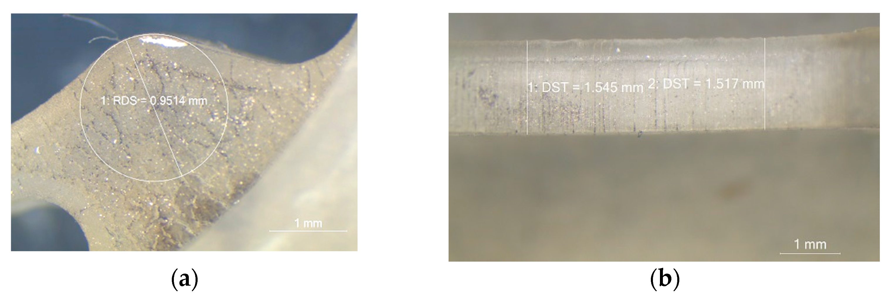
4.1. Geometry and Stiffness Verification

Preliminary testing on a single disk was already performed, as shown by the authors in [29]. The flexible structures were tested to identify the stiffness in the axial direction. A proper setup was designed: the force was measured with a load cell based on strain gauges (5 N range, 967(7) 10−1 mV/N sensitivity), whereas the displacement was measured by micrometric slide (Mitutoyo, 0.01 mm resolution). During the tests, the maximum deformation at the pad was kept at 0.45 mm maximum. The measured average axial stiffness was about 1.306 N/mm, with a standard deviation of the measurement repeatability lower than 1% of the average value. Size measurement was performed as well by an electrical microscope in different areas of the manufactured disks, as shown in Figure 7a,b.
Measurements showed that the maximum geometrical deviation from the numerical model was about 6% for the thickness of the bottom and top disks. This result confirmed that the manufacturing process can achieve the nominal designed size, granting the mechanical performance of the conceived kinematic mounting.

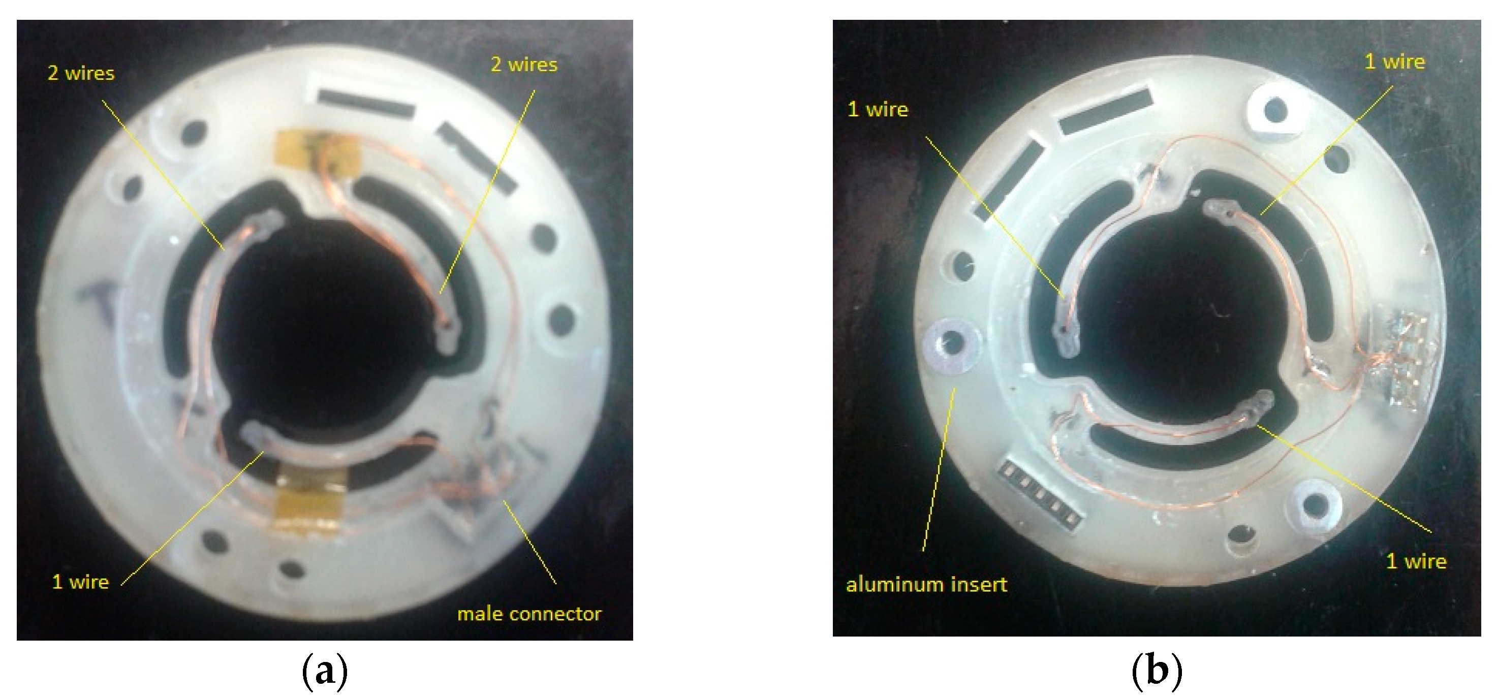
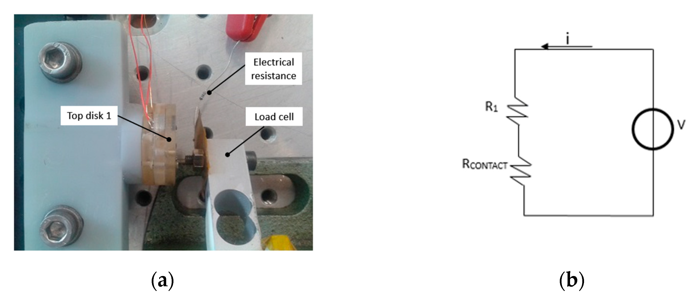
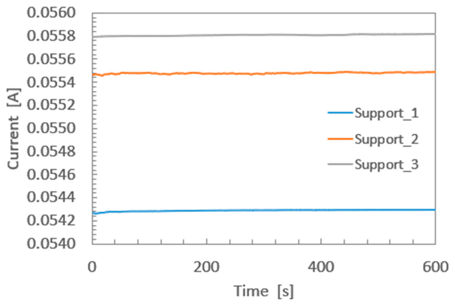
4.2. Electrical Contacts

The stability of the electrical conductance given by the conductive paint on the pads was tested. A setup was designed to provide stable mechanical contact, by using a micrometric slide and a load cell to measure the force during the test. The set point was the expected working condition given by the preloading of the flexible structure when the crystal is mounted, i.e., about 0.4 N. A view of the developed setup is shown in Figure 8a. The electrical contact with the pad was assured by using a screw, mechanically connected with the load cell, while electrically connected by a brass foil with a reference electrical resistance (R1, 120 Ω ± 0.5%). The equivalent electrical circuit for the test is shown in Figure 8b. A voltage generator feeds the circuit, and a current meter (Agilent 34450A) was used to assess the stability of the current (i) and, therefore, of the electrical resistance (RCONTACT) given by the contact between the pads and the foil. Three different voltages were applied, i.e., 7 V, 9 V, and 10 V. Each condition was kept for at least 10 min.
Figure 9 shows the measured current for the bottom disk, with a 7 V supply voltage, whereas Table 3 summarizes measured statistics for the tested flexible supports in the worst-case scenario, i.e., 10 V supply voltage.
Obtained results showed that the electrical resistance at the contact was stable for all the tested pads, validating the possibility of using the conductive paint at the maximum voltage. Maximum variability in the tested condition was less than 0.1% of the average value.

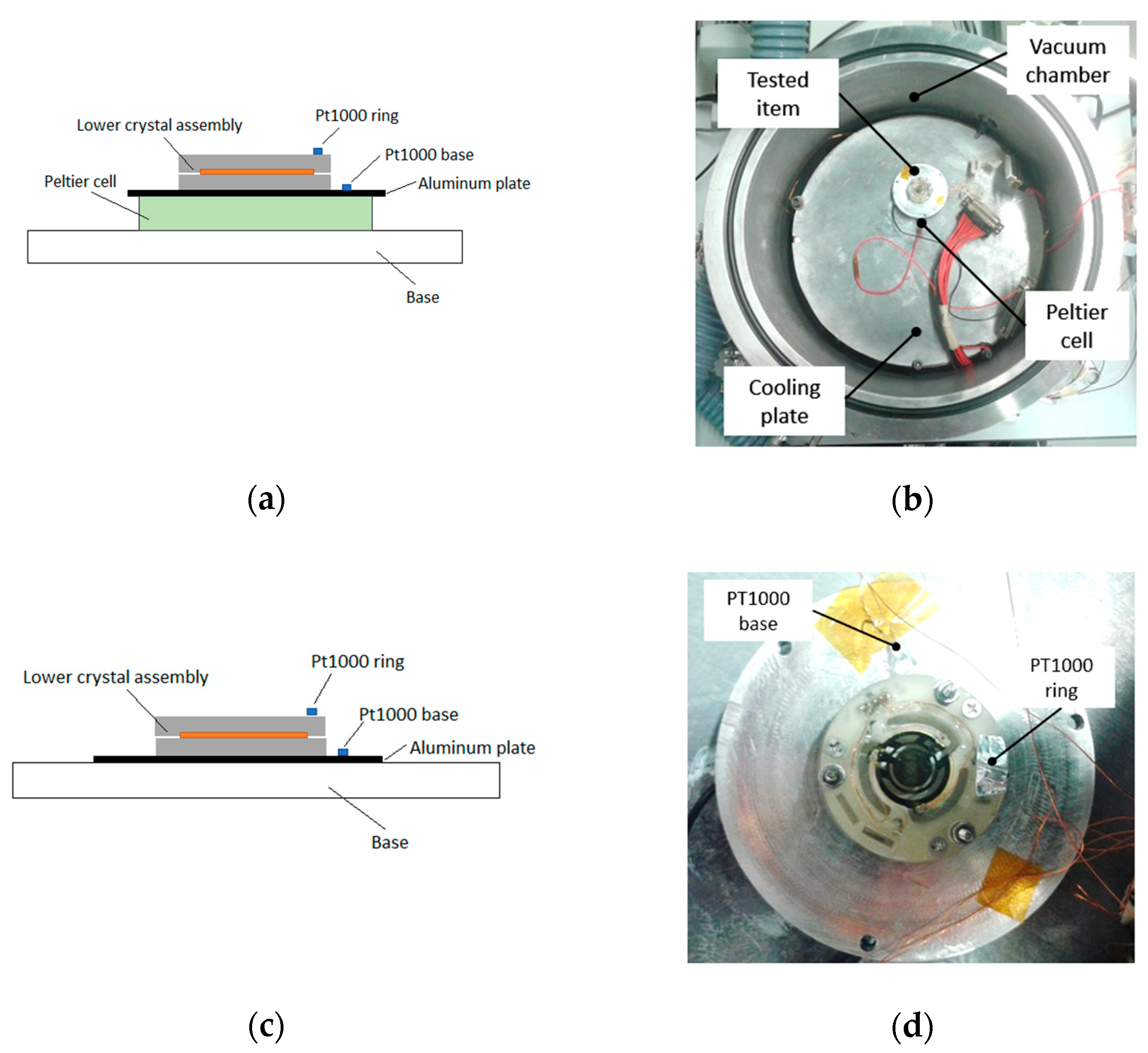
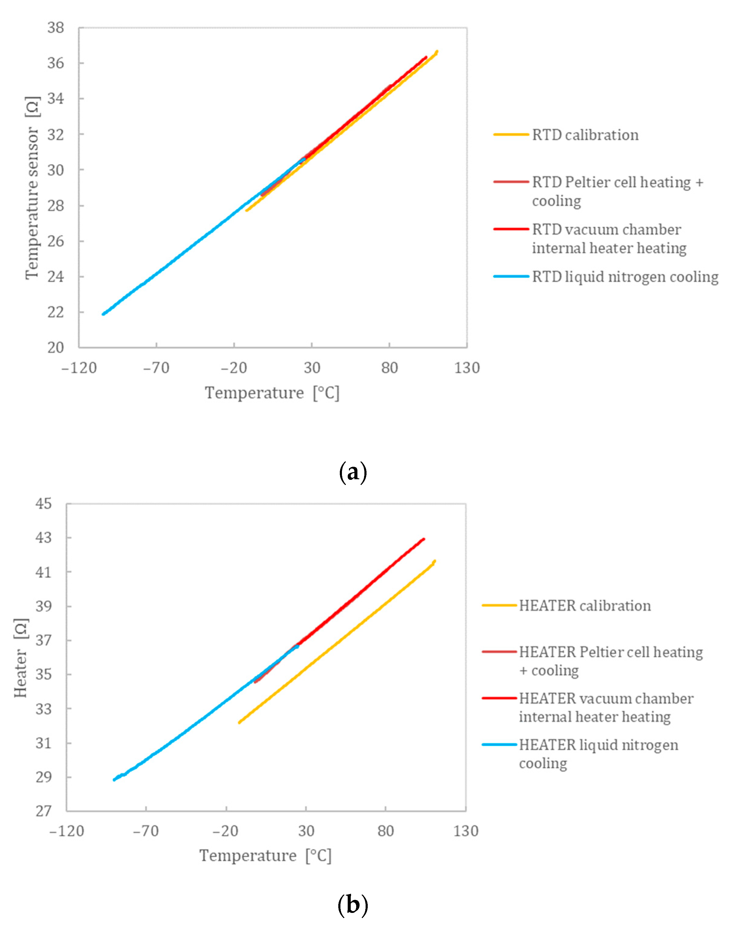
4.3. Thermal Testing

The thermal testing aimed to verify the mechanical resistance of the quasi-kinematic mounting in a relevant temperature range. The item was subjected to heating and cooling cycles in low-pressure conditions, i.e., at 10−3 mbar, the latter being the lowest value achievable with the thermo-vacuum setup. Two similar setups were used: for the heating and cooling within a limited range of temperature, i.e., between −20 °C and 80 °C, a Peltier cell was positioned below the tested item. The scheme of the setup is shown in Figure 10a, whereas the tested item is highlighted in Figure 10b.
For cooling and heating within a larger temperature range, i.e., between −110 °C and 110 °C, the Peltier cell was removed (as shown in Figure 10c), and cooling and heating were controlled with a cooling circuit and heater directly mounted at the interface base. In both cases, two Pt1000 class A were used to monitor the temperature of the crystal holder and the mounting base. The oscillating frequency of the crystal was measured by a proper electronics and frequency counter (model type HP Agilent Keysight 53220A), at stable temperatures. Moreover, the electrical resistance of the deposited resistors was measured by an Agilent multiplexing unit by four wires method. It has to be noticed that these resistors were previously calibrated in a thermal bath as a reference. Figure 11 compares the measured resistances in different conditions: as can be seen from the obtained results, the slopes of the electrical resistance vs. temperature are compatible with those obtained during the crystal calibration phase, therefore confirming the correct functionality of the supporting structure for the thermo-vacuum testing. Moreover, the obtained results highlighted the good linearity of the deposited resistors, as already shown in reference [30]. Eventually, the measured resonances of the crystal were found to be 9.970 MHz and 9.966 MHz at 110 °C and −110 °C, respectively. These values were compatible with the measured resonance at ambient temperature, i.e., 9.969 MHz, as additional validation of the functionality of the quasi-kinematic holder and its electrical contacts.

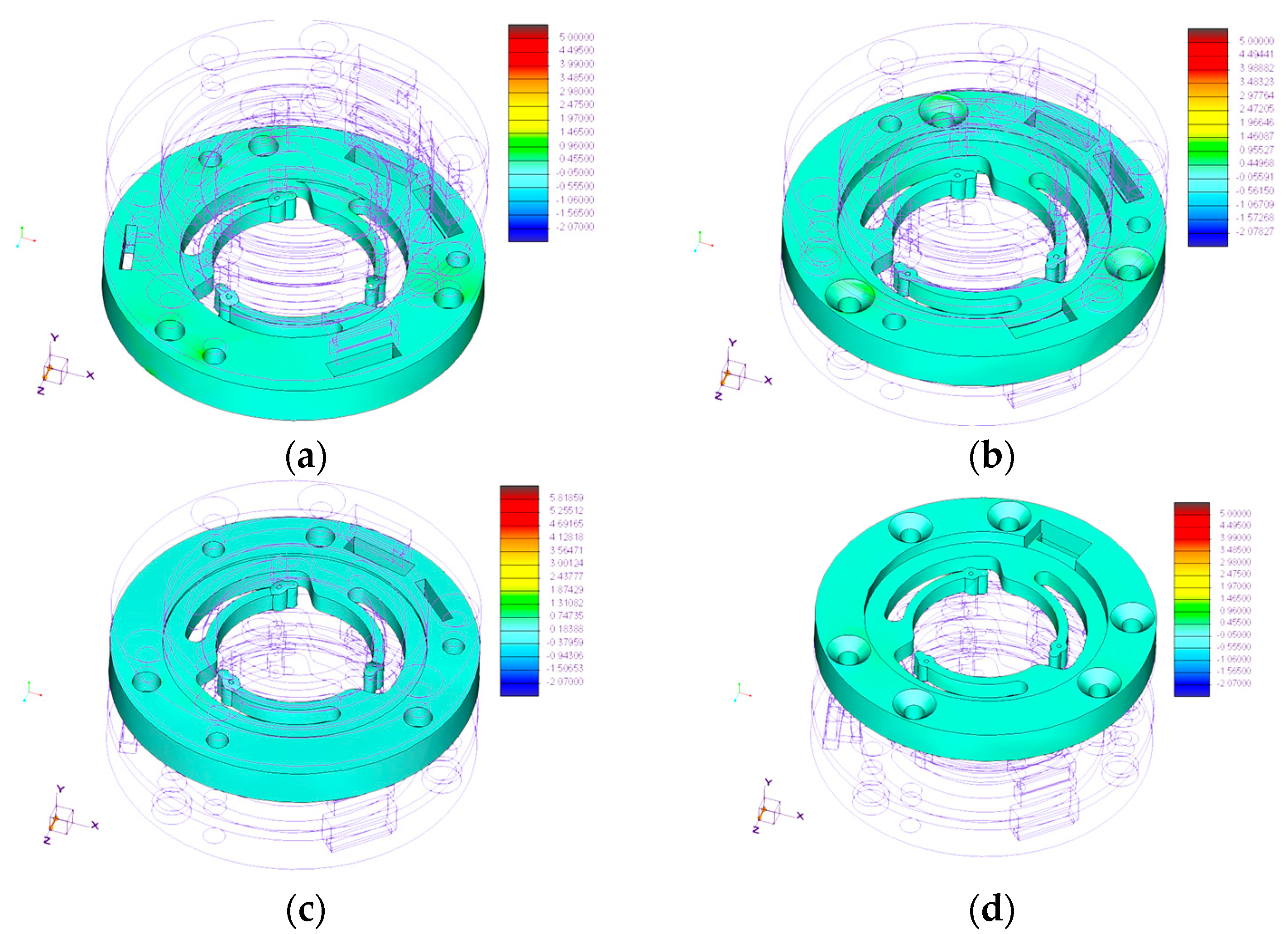
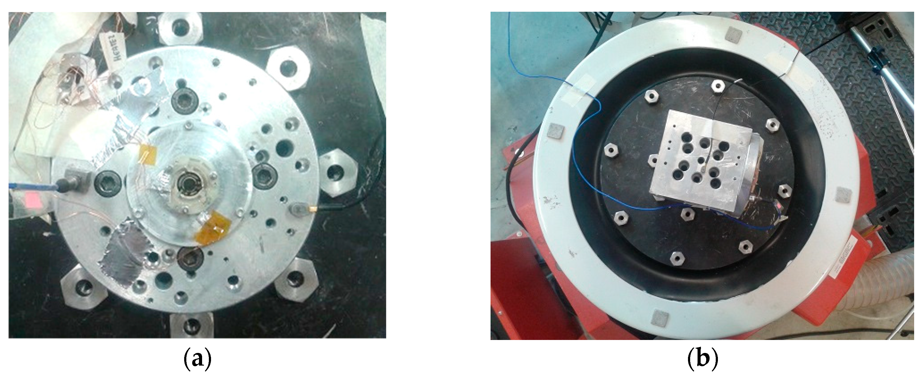
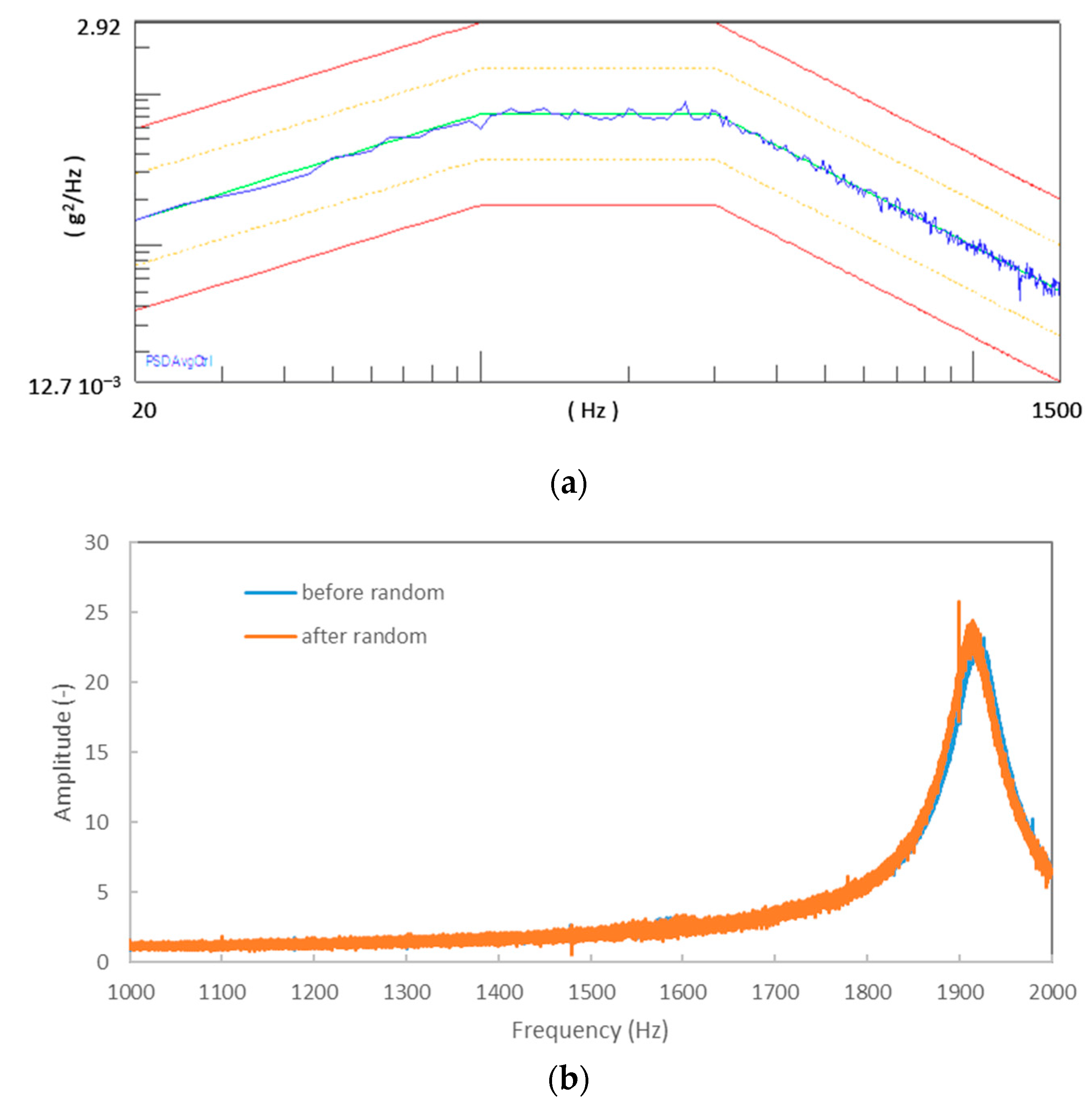
4.4. Mechanical Testing

Mechanical qualification required testing of the quasi-kinematic supporting structure in a representative vibration environment. Two accelerometers were mounted at the shaker interface to measure the feedback control of the shaker (reference accelerometer) and the input acceleration (measurement accelerometer). For the out-of-plane testing, the item was mounted as shown in Figure 12a, whereas for the in-plane testing, a proper interface was added to the shaker head.
The acceleration of the crystal was measured by a Polytec vibrometer OFV-500, whose spot was focused on the crystal during vertical vibration or on the supports for the in-plane excitations. Both accelerometers were fed and amplified by a Bruel & Kjaer Nexus conditioning unit. The qualification procedure consisted of the following steps:
  • Initial resonance search: a low amplitude sweep sine test between 20 and 2000 Hz, with an acceleration amplitude of 5 m/s2 and a sweep rate of 2 oct/min;
  • Random excitation from 20 to 2000 Hz with an equivalent RMS of 500 m/s2 for a total time of 2.5 min in the tested direction, as shown in Figure 13a;
  • Final resonance search: low amplitude sweep sine test.
Applied random vibration was derived from the expected profile obtained by the ECSS E-10-03 Testing. Visual inspection was performed after each test to search for damages on the supports or the crystal. Moreover, the electrical resistance of the deposited resistors was measured before and after each power test. Measured frequency response functions showed a maximum deviation of the resonance peak of about 2 Hz, i.e., less than 0.5% of the resonance of the mechanical structure, proving that no significant changes happened during mechanical testing. Additional validation was achieved by comparing the measured electrical resistance of the deposited temperature sensor and heater before and after the random tests. It was found that electrical resistance for the deposited resistors was set to an average of 30.7 Ω and 36.9 Ω, and a maximum deviation of 0.2 Ω was measured. Thus, thanks to the compatibility of the measured electrical resistances and the successful visual inspection of the tested item in each phase of the mechanical testing, the characterization considering the used qualification levels was considered successfully passed.

5. Conclusions

A 3D printed quasi-kinematic support for a quartz crystal microbalance was designed to achieve a compact and lightweight solution but, at the same time, suitable for space applications and compliant with harsh thermal and mechanical environments. The usage of an off-a-shelf high-temperature resin for stereolithography printing was investigated. The finite element modeling guided the design phase, achieving an effective solution to cope with the thermal and mechanical design requirements and assessing the expected performances by numerical analyses in the expected working scenarios. The conceived quasi-kinematic mounting is of paramount importance to allow for the survival of the quartz crystal microbalance in a temperature range between 150 °C and −200 °C and the mechanical resistance vs. quasi-static acceleration of 1000 m/s2. Moreover, considering the functional requirements related to the acquisition of the microbalance signal and the control of the operative conditions for the thermogravimetric analyses, the designed solution effectively provides all the electrical connections needed for the sensor and grants robust working in the thermal environment.
Manufacturing and integration of a mockup were completed and underwent a testing campaign to verify the stability of the electrical contacts and the mechanical resistance in representative thermo-vacuum and mechanical environments. Thermal tests provided mechanical resistance and functionality verification between −110 °C and 110 °C, whereas the mechanical tests validated the proposed design in a worst-case scenario for the random vibration excitation, characterized by high acceleration levels and power spectral density with an RMS acceleration value of 500 m/s2.
Indeed, the obtained numerical and experimental results allow for proposing the developed sensor for future space missions, e.g., measuring material outgassing properties and on-orbit contamination onboard CubeSat or small payloads. The next developments envisaged for the activity are the integration of proximity electronics and the qualification of the sensor in a representative radiation environment.

Author Contributions

Conceptualization, D.S. and M.M.; methodology, D.S., B.S., M.M., M.G.C. and P.V.; investigation, D.S., B.S., M.M., M.G.C., P.V., E.P., A.L., F.D. and E.Z.; resources, B.S. and D.S.; data curation, D.S., B.S., M.M., M.G.C. and P.V.; writing—original draft preparation, D.S. and M.M.; writing—review and editing, D.S., B.S., M.M., M.G.C., P.V., E.P., A.L., F.D. and E.Z.; supervision, D.S. All authors have read and agreed to the published version of the manuscript.

Funding

This research received no external funding.

Institutional Review Board Statement

Not applicable.

Informed Consent Statement

Not applicable.

Data Availability Statement

Not applicable.

Acknowledgments

The authors would like to acknowledge Marco Conca for his support in this activity.

Conflicts of Interest

The authors declare no conflict of interest.

References

  1. Kobryn, P.A.; Ontko, N.R.; Perkins, L.P.; Tiley, J.S. Additive Manufacturing of Aerospace Alloys for Aircraft Structures; Air Force Research Lab Wright-Patterson AFB OH Materials and Manufacturing Directorate: Wright-Patterson Air Force Base, OH, USA, 2006. [Google Scholar]
  2. Schiller, G.J. Additive Manufacturing for Aerospace. In Proceedings of the 2015 IEEE Aerospace Conference, Big Sky, MT, USA, 7–14 March 2015; pp. 1–8. [Google Scholar]
  3. Gibson, I.; Rosen, D.; Stucker, B.; Khorasani, M. Development of additive manufacturing technology. In Additive Manufacturing Technologies; Springer: Berlin/Heidelberg, Germany, 2021; pp. 23–51. [Google Scholar]
  4. Goh, G.D.; Agarwala, S.; Goh, G.L.; Dikshit, V.; Sing, S.L.; Yeong, W.Y. Additive Manufacturing in Unmanned Aerial Vehicles (UAVs): Challenges and Potential. Aerosp. Sci. Technol. 2017, 63, 140–151. [Google Scholar] [CrossRef]
  5. Najmon, J.C.; Raeisi, S.; Tovar, A. Review of Additive Manufacturing Technologies and Applications in the Aerospace Industry. In Additive Manufacturing for the Aerospace Industry; Elsevier: Amsterdam, The Netherlands, 2019; pp. 7–31. [Google Scholar]
  6. Rinaldi, M.; Ferrara, M.; Pigliaru, L.; Allegranza, C.; Nanni, F. Additive Manufacturing of Polyether Ether Ketone-Based Composites for Space Application: A Mini-Review. CEAS Space J. 2021, 2021, 1–11. [Google Scholar] [CrossRef]
  7. Rinaldi, M.; Cecchini, F.; Pigliaru, L.; Ghidini, T.; Lumaca, F.; Nanni, F. Additive Manufacturing of Polyether Ether Ketone (Peek) for Space Applications: A Nanosat Polymeric Structure. Polymers 2020, 13, 11. [Google Scholar] [CrossRef] [PubMed]
  8. Boschetto, A.; Bottini, L.; Eugeni, M.; Cardini, V.; Nisi, G.G.; Veniali, F.; Gaudenzi, P. Selective Laser Melting of a 1u Cubesat Structure. Design for Additive Manufacturing and Assembly. Acta Astronaut. 2019, 159, 377–384. [Google Scholar] [CrossRef]
  9. Godec, M.; Malej, S.; Feizpour, D.; Donik, Č.; Balažic, M.; Klobčar, D.; Pambaguian, L.; Conradi, M.; Kocijan, A. Hybrid Additive Manufacturing of Inconel 718 for Future Space Applications. Mater. Charact. 2021, 172, 110842. [Google Scholar] [CrossRef]
  10. Romei, F.; Grubišić, A.N. Validation of an Additively Manufactured Resistojet through Experimental and Computational Analysis. Acta Astronaut. 2020, 167, 14–22. [Google Scholar] [CrossRef]
  11. Fiocchi, J.; Biffi, C.A.; Scaccabarozzi, D.; Saggin, B.; Tuissi, A. Enhancement of the Damping Behavior of Ti6Al4V Alloy through the use of Trabecular Structure Produced by Selective Laser Melting. Adv. Eng. Mater. 2020, 22, 1900722. [Google Scholar] [CrossRef]
  12. Colombo, C.; Biffi, C.A.; Fiocchi, J.; Scaccabarozzi, D.; Saggin, B.; Tuissi, A.; Vergani, L.M. Modulating the Damping Capacity of SLMed AlSi10Mg Trough Stress-Relieving Thermal Treatments. Theor. Appl. Fract. Mech. 2020, 107, 102537. [Google Scholar] [CrossRef]
  13. Spears, T.G.; Gold, S.A. In-Process Sensing in Selective Laser Melting (SLM) Additive Manufacturing. Integr. Mater. Manuf. Innov. 2016, 5, 16–40. [Google Scholar] [CrossRef] [Green Version]
  14. Rebaioli, L.; Fassi, I. A Review on Benchmark Artifacts for Evaluating the Geometrical Performance of Additive Manufacturing Processes. Int. J. Adv. Manuf. Technol. 2017, 93, 2571–2598. [Google Scholar] [CrossRef]
  15. Rupal, B.S.; Anwer, N.; Secanell, M.; Qureshi, A.J. Geometric Tolerance and Manufacturing Assemblability Estimation of Metal Additive Manufacturing (AM) Processes. Mater. Des. 2020, 194, 108842. [Google Scholar] [CrossRef]
  16. Brice, C.A. Unintended Consequences: How Qualification Constrains Innovation. In Proceedings of the 1st World Congress on Integrated Computational Materials Engineering (ICME), Seven Springs, PA, USA, 10–14 July 2011. [Google Scholar]
  17. Sacco, E.; Moon, S.K. Additive Manufacturing for Space: Status and Promises. Int. J. Adv. Manuf. Technol. 2019, 105, 4123–4146. [Google Scholar] [CrossRef]
  18. Dordlofva, C.; Törlind, P. Qualification Challenges with Additive Manufacturing in Space Applications. In Proceedings of the 2017 International Solid Freeform Fabrication Symposium, Austin, TX, USA, 7–9 August 2017. [Google Scholar]
  19. VDI. VDI 3405-3-4: Additive Manufacturing Processes—Design Rules for Part Production Using Material Extrusion Processes; VDI: Düsseldorf, Germany, 2019. [Google Scholar]
  20. Krueger, H. Standardization for Additive Manufacturing in Aerospace. Engineering 2017, 3, 585. [Google Scholar] [CrossRef]
  21. Scaccabarozzi, D.; Saggin, B.; Tarabini, M.; Palomba, E.; Longobardo, A.; Zampetti, E. Thermo-Mechanical Design and Testing of a Microbalance for Space Applications. Adv. Space Res. 2014, 54, 2386–2397. [Google Scholar] [CrossRef]
  22. Dirri, F.; Palomba, E.; Longobardo, A.; Zampetti, E.; Saggin, B.; Scaccabarozzi, D. A Review of Quartz Crystal Microbalances for Space Applications. Sens. Actuators A Phys. 2019, 287, 48–75. [Google Scholar] [CrossRef]
  23. Scaccabarozzi, D.; Saggin, B.; Corti, M.G.; Arrigoni, S.; Valnegri, P.; Dirri, F.; Gisellu, C.; Palomba, E.; Longobardo, A.; Zampetti, E. Design of VISTA, a Quartz Crystal Thermogravimetric Analyzer for Hera Mission. In Proceedings of the 2022 IEEE 9th International Workshop on Metrology for AeroSpace (MetroAeroSpace), Pisa, Italy, 27–29 June 2022; pp. 28–32. [Google Scholar]
  24. Yoder, P.R. Mounting Optics in Optical Instruments.; SPIE Press: Bellingham, WA, USA, 2008. [Google Scholar]
  25. Saggin, B.; Scaccabarozzi, D.; Shatalina, I.; Panzeri, R.; Tarabini, M.; Magni, M.; Bellucci, G. MicroMIMA, a Miniaturized Spectrometer for Planetary Observation. In Proceedings of the 2015 IEEE Metrology for Aerospace (MetroAeroSpace), Benevento, Italy, 4–5 June 2015; pp. 502–506. [Google Scholar]
  26. Dirri, F.; Palomba, E.; Longobardo, A.; Biondi, D.; Boccaccini, A.; Galiano, A.; Zampetti, E.; Saggin, B.; Scaccabarozzi, D.; Martin-Torres, J. VISTA Instrument: A PCM-Based Sensor for Organics and Volatiles Characterization by using Thermogravimetric Technique. In Proceedings of the 2018 5th IEEE International Workshop on Metrology for AeroSpace (MetroAeroSpace), Rome, Italy, 20–22 June 2018; pp. 150–154. [Google Scholar]
  27. Hopping, E.P.; Huang, W.; Xu, K.G. Small Hall Effect Thruster with 3D Printed Discharge Channel: Design and Thrust Measurements. Aerospace 2021, 8, 227. [Google Scholar] [CrossRef]
  28. Becedas, J.; Caparrós, A.; Ramírez, A.; Morillo, P.; Sarachaga, E.; Martín-Moreno, A. Advanced Space Flight Mechanical Qualification Test of a 3D-Printed Satellite Structure Produced in Polyetherimide ULTEM™. In Advanced Engineering Testing; IntechOpen: London, UK, 2018. [Google Scholar]
  29. Scaccabarozzi, D.; Saggin, B.; Magni, M.; Valnegri, P.; Corti, M.G.; Palomba, E.; Longobardo, A.; Dirri, F.; Zampetti, E. Design of 3D Printed Holder for Quartz Crystal Microbalances. In Proceedings of the 2021 IEEE 8th International Workshop on Metrology for AeroSpace (MetroAeroSpace), Naples, Italy, 23–25 June 2021; pp. 715–719. [Google Scholar]
  30. Scaccabarozzi, D.; Saggin, B.; Magni, M.; Corti, M.G.; Zampetti, E.; Palomba, E.; Longobardo, A.; Dirri, F. Calibration in Cryogenic Conditions of Deposited Thin-Film Thermometers on Quartz Crystal Microbalances. Sens. Actuators A Phys. 2021, 330, 112878. [Google Scholar] [CrossRef]
Figure 1. (a) Scheme of the quasi-kinematic mounting (b) single disk geometry.
Aerospace 10 00042 g001
Figure 2. (a) 3D model of the double crystal configuration (b) section view of the microbalance.
Aerospace 10 00042 g002
Figure 3. Modal analysis results: (a) the first mode of vibration, (b) the second mode of vibration.
Aerospace 10 00042 g003
Figure 4. Max principal stress [MPa] on the model with quasi-static loading of 100 G in Z direction: (a) bottom disk 2, (b) top disk 2, (c) bottom disk 1, (d) top disk 1, (e) bottom crystal and (f) top crystal.
Aerospace 10 00042 g004aAerospace 10 00042 g004b
Figure 5. Maximum principal stress [MPa] distribution in the thermoelastic analysis, cold case with the uniform temperature distribution at −190 °C.
Aerospace 10 00042 g005
Figure 6. (a) Top disk and (b) bottom disk.
Aerospace 10 00042 g006
Figure 7. (a) Detailed view of the flexible support for the top disk near the connection between the flexible structure and the disk; (b) detailed view of the flexible support thickness.
Aerospace 10 00042 g007
Figure 8. (a) Detailed view of the setup to validate the electrical contact; (b) electrical scheme of the system.
Aerospace 10 00042 g008
Figure 9. Measured current for bottom disk, 7 V power supply.
Aerospace 10 00042 g009
Figure 10. (a) Scheme of the heating test setup; (b) view of the tested item in the vacuum chamber; (c) scheme of the test during cooling; (d) detailed view of the temperature sensors on the tested item.
Aerospace 10 00042 g010
Figure 11. (a) Measured resistance for the deposited temperature sensor; (b) measured resistance for the deposited heater.
Aerospace 10 00042 g011
Figure 12. (a) Test setup for out-of-plane testing; (b) test setup for in-plane testing.
Aerospace 10 00042 g012
Figure 13. (a) Random level for the in-plane and out-of-plane tests; (b) measured frequency response functions before and after the random excitation for the out-of-plane test.
Aerospace 10 00042 g013
Table 1. Mechanical characteristics of the used materials.
QuartzFLHTAM 02
Flexural modulus (MPa)97,2002800
Density (kg m−3)26481100
Poisson’s ratio0.170.36
σ limit -tension (MPa)4748.7
σ limit -compression (MPa)1100n.a.
σ limit -bending (MPa)4197.2
CTE (°C−1)7.1 × 10−674.5 × 10⁻⁶
Table 2. Computed modes of vibration for the double-crystal microbalance.
Mode NumberEigenfrequency (Hz)
11739
21748
32074
Table 3. Measured current statistics with 10 V supply voltage.
SupportMean (mA)Standard deviation (mA)
1 top disk79.835.9 × 10−3
2 top disk78.927.3 × 10−3
3 top disk79.658.1 × 10−3
1 bottom disk77.681.6 × 10−3
2 bottom disk79.545.1 × 10−3
3 bottom disk79.673.2 × 10−3
Disclaimer/Publisher’s Note: The statements, opinions and data contained in all publications are solely those of the individual author(s) and contributor(s) and not of MDPI and/or the editor(s). MDPI and/or the editor(s) disclaim responsibility for any injury to people or property resulting from any ideas, methods, instructions or products referred to in the content.

