Article

Thrust Control Method and Technology of Variable-Thrust Liquid Engine for Reusable Launch Rocket

1
College of Energy and Power Engineering, Nanjing University of Aeronautics and Astronautics, Nanjing 210016, China
2
College of Electrical Engineering and Automation, Fuzhou University, Fuzhou 350108, China
3
College of Energy Science and Engineering, Harbin Institute of Technology, Harbin 150001, China
*
Author to whom correspondence should be addressed.
Aerospace 2023, 10(1), 32; https://doi.org/10.3390/aerospace10010032
Submission received: 19 October 2022 / Revised: 23 December 2022 / Accepted: 23 December 2022 / Published: 30 December 2022
(This article belongs to the Special Issue Liquid Rocket Engines)

Abstract

:
A high-precision variable-thrust control method based on real-time measurement of pintle displacement and closed-loop feedback control is proposed to solve the technical problems of deep throttling variable-thrust regulation and control of pintle liquid rocket engines (LRE). By optimizing the system structure and control parameters, the closed-loop control of displacement with high precision and a fast response under a wide range of variable thrust can be realized, and thus the large-range, fast-response, and high-precision control of the chamber pressure, equivalent to thrust, can be indirectly realized. The chamber pressure response time is not more than 0.3 s, the overshoot is not more than ±3%, and the pulsation amplitude is not more than ±5%, which can meet the technical requirements of the large-range thrust adjustment and control of variable-thrust LRE of reusable launch rockets. The proposed variable-thrust LRE thrust control system is simple, reliable, and easy to use and maintain, which solves the problem of the large range, high precision, and fast response of thrust adjustment and control. The proposed system can provide important technical support for carrier rocket recycling and launch cost reduction. This is the first time a closed-loop control method of displacement of an integrated gas generator/flow regulator to achieve a 5:1 large-range continuous-variable-thrust control for the LRE of a reusable launch rocket has been proposed.

1. Introduction

Variable-thrust liquid rocket engine (LRE) technology is an important field of liquid rocket propulsion technology [1]. LREs with thrust control capability show great technical superiority in space transportation and space maneuvering flights [2,3,4]. In addition, variable-thrust LREs are currently the only devices available for soft landing and maneuvering flights on the surface of airless bodies [5]. For example, after the success of the Apollo spacecraft, which relied on the Lunar Module Descent Engine (LMDE), the United States became the first country to achieve a manned lunar landing [6,7,8]. Chang’e 3 successfully achieved midcourse correction, lunar braking, powered descending, and hovering during the soft landing on the Moon using a 7500 N variable-thrust engine [9,10]. As a rocket engine is a high-density energy-release device, many technical problems with regard to optimization design and thrust control need to be solved, because those problems of a variable-thrust LRE are quite different from those of a fixed- thrust LRE.
The injector design is very important in the design of a variable-thrust LRE. Because of its unique geometric and injection characteristics, a pintle injector could produce high combustion efficiency under each variable-thrust condition, and has the characteristics of strong adjustment ability for wide-range thrust varying application occasions, lower cost compared to a complex external adjustment mechanism, and a high reliability because of the single moving pintle. Therefore, the international research on variable-thrust LRE is mainly focused on the use of pintle injector LREs [11,12,13,14,15,16,17,18,19,20,21,22,23]. Many methods for the variable-thrust control of liquid rocket motors have been proposed in the literature, but most of them remain at the theoretical level. To this point, controlling the injector area and propellant mass flow rate in the supply system remains the main method of achieving the thrust regulation of LRE [24,25], with many different approaches, including the monotone method, double adjustment, traffic location systems, the adjustable area of a cavitating Venturi tube combined with a fixed-section injection device, and a throttling valve regulating the dual supply of a turbine pump flow. The most famous variable-thrust LRE is the MIRA-10K, MIRA-10500 series engine developed in the 1960s for the Apollo Lunar Module soft landing [3]. MIRA-10K series engines adopt a mechanical connection scheme of dual variable cross-section injectors and variable cross-section Venturi tube flow control valves [26,27]. When thrust adjustment is needed, the plunger in the throttle valve and the connected injector pintle are moved by an electric action mechanism so that the flow area of the throttle valve changes. The movement of the pintle changes the injection area of the oxidizer and fuel, thus achieving a wide range of thrust regulation of 10:1. The structure and mechanical connection scheme of Venturi tube flow control valves [6,28,29] of MIRA-10K series LREs is shown in Figure 1.
One of Falcon 9’s rocket stages is powered by nine Merlin-1D variable-thrust liquid oxygen/kerosene engines. The key to Falcon 9’s reusable capability is its use of the same pinch-and-pintle injectors found in the Apollo descent engines, which allow for thrust adjustment ranging from 100% to 39% [30]. Giuliano et al. [31,32] carried out research work on the Lunar Module’s large variable-ratio engine. In the engine pipeline, the bypass valve was used to adjust the flow to achieve thrust regulation, and the thrust control valve and turbine bypass valve were used to adjust the flow into the turbine to change the thrust. The 11.4:1 large variable-ratio thrust regulation test was successfully achieved.
Variable-thrust LRE technology is one of the key technologies needed to realize reusable launch rockets. For landing a rocket, the first stage the rocket needs to start the LRE again during the landing phase, and a much lower thrust backward toward the center of the earth is acting on the rocket so that the rocket can slowly descend and land on the landing platform at zero altitude and zero speed. This technology develops the traditional single-use rocket into a reusable multi-use rocket, making an important technical contribution to the substantial reduction in the specific launch cost [31,33,34,35,36,37,38,39]. This technology has also provided the motivation for scholars to carry out continuous research work in the field of LRE deep throttling variable-thrust technology for a long time. For example, Zhou [40] presented the components, working principle, and adjustment process of a variable injector cross-section bivariate thrust LRE controlled by a solenoid valve. According to the requirements of the control system, the structural parameters of the engine’s adjustable Venturi tube-injector system were selected and designed, and the dynamic and steady performance of the engine control system was presented. Zhang et al. [41] analyzed the response characteristics of a variable-thrust LRE with an adjustable injector and adjustable Venturi tube. The main factors affecting the dynamic performance of the variable-thrust LRE were discussed, and the theoretical analysis and experimental study of the pulse width sampling digital control system of the variable-thrust LRE were carried out. The key factors affecting the dynamic and static response and the difference between them and the general proportional feedback control were also pointed out. Cui, Liang et al. [42,43,44,45] have carried out a lot of constructive research in the field of LRE control, which can provide a reference for our research. A high-order sliding mode control method of an LRE with a variable thrust was published in [46], and ref. [47] studied the dynamic response characteristics of a dual-channel injector variable-thrust LRE. These studies have laid an important foundation for the research of variable-thrust control methods and technology [48,49,50,51].
As mentioned above, one of the most important technologies to realize the recovery landing of rockets is variable-thrust LRE technology, and the realization of the variable thrust of engines requires a wide-range, synchronous pintle propellant injecting and flow regulation [6,28,29]. Under this background, this paper proposes and verifies a thrust control scheme based on the displacement closed-loop control of a structurally integrated gas generator/flow regulator, in order to provide wide-range, high-precision thrust control in the rocket recovery stage and ensure a smooth and safe landing of the rocket. In fact, up to now, there is no precedent worldwide for researchers to propose a closed-loop control method of displacement of an integrated gas generator/flow regulator to achieve a 5:1 large-range continuous-thrust control for LRE by controlling pintle position or chamber pressure because the thrust, mass flow rate, pintle displacement and chamber pressure are a one-to-one monotonic relationship. Thus, this article is an innovation in the field.

2. Working Principle and Model of Variable-Thrust Control System for Liquid Rocket Engine

2.1. Composition and Working Principle of Thrust Adjustment System

Before starting the discussion of the control system in this paper, it needs to be clear that this paper is carried out under the framework of an 80-ton variable-thrust rocket engine. The control system in this paper is one part of the 80-ton complex LRE system.
The composition and working principle of the variable-thrust control system of a bipropellant pintle LRE are shown in Figure 2. The system is mainly composed of an integrated flow regulator/gas generator (IFRGG), an engine controller, a Linear Variable Differential Transformer (LVDT) displacement sensor xpin, four pressure sensors, Pif, Pio, Pc, Pgg, an electric area-adjustable orifice, a control solenoid valve, a oxidizer value, a fuel value, a PWM (Pulse Width Modulation), a high-speed solenoid valve, and a cable family. In particular, the IFRGG is mainly composed of a sleeve, pintle, plug (with several grooves, commonly it is 3~12), and body. In the IFRGG, the pintle is the only movable component which will move left or right in a straight line under both the force action of control fluid Pc and combustion gas Pgg. The left half of the integrated device is a complex dual-propellant synchronous flow regulator, and the right side is a gas generator body; the two liquid propellants will organize combustion and produce high-temperature gas here. Pgg is a sensor for measuring combustion pressure. Therefore, this is an integration of a flow regulator and a gas generator. The requirements for the control system are: (1) the adjustment of the two propellants must be synchronous; (2) minimal sensor measurement error; (3) a rapid response time, generally less than 0.3 s; and (4) no large overshoot of the controlled variable (generally less than ±3%).
The oxidizer enters via the center of the IFRGG and is sprayed radially into the body chamber from the groove of the pintle, while the fuel enters from the outside axially into the body chamber along the outer ring seam of the pintle. By moving the pintle axially, the relative position of the two flow channel of oxidizer and fuel propellants is changed, thus changing the minimum flow area of the two propellants as well as the mass flow rate. A line displacement sensor is installed on the pintle to sense the position of the pintle in real time. The movement of the pintle is realized by changing the control pressure of the control chamber, and the change in the control pressure is realized by controlling the PWM valve control duty ratio.
As the working efficiency of the thrust chamber, pump, turbine, generator and other components is different under different thrust conditions, and the flow resistance of the liquid flow component is square with the mass flow rate, so the engine thrust cannot be proportional to the displacement of the pintle.
However, generally speaking, the engine thrust and the pintle displacement is a one-to-one monotone correspondence relationship. Therefore, the logic of this paper is as follows: firstly, by carrying out a cold-flow regulation characteristic experiment, the real corresponding relationship between displacement and thrust can be obtained, which is called a thrust regulation characteristics. Then, in a real flight experiment, as the thrust is not measurable, the thrust-displacement characteristic is used to set the pintle displacement command, and the displacement is measured and closed-loop controlled to achieve a thrust closed-loop control.
As a pintle displacement can be measured accurately and feed-back closed-loop controlled, which avoids the challenge of direct measurement of the combustion pressure, this makes the LRE control system much simpler.

2.2. Dynamic Model of Thrust Adjustment System

As shown in Equation (1), ε is defined as the working condition factor of the variable-thrust LRE. It represents the ratio of the current sea-level thrust F of variable-thrust LRE to the rated sea-level thrust F g .
ε = F F g ,   0.2 ε 1 . 2
According to the thrust of the variable-thrust LRE under different working conditions, the chamber pressure P g g ( ε ) and mass flow rate q m g ( ε ) of the IFRGG can be determined. k m is oxidizer to the fuel mass ratio of the IFRGG, whose design value is generally at a rich-fuel state of 0.3~0.5 to generate a 1250 K-temperature gas. According to the oxidizer to fuel mass ratio k m , the oxidant and fuel flow target design values under different working conditions can be determined, as shown in Equations (2) and (3).
q m f ( ε ) = 1 1 + k m q m g ( ε )
q m o ( ε ) = q m g ( ε ) q m f ( ε )
where q m g is the total mass flow rate of the IFRGG, q m f is the fuel flow of the IFRGG, and q m o is the oxidizer mass flow of the IFRGG.
The oxidizer to fuel mass ratio km here refers to IFRGG, not the thrust chamber, nor LRE. This km is a design value and a target value which we hope will remain unchanged during a variable thrust operation. Thus, it is assumed that km is independent of ε in the determination of chamber pressure and mass flow rate. This is why an integrated synchronous regulation of the two propellants is proposed, designed, and a control system based on this is conducted. In the actual variable thrust working process, due to a different combustion efficiency, control error, etc., the gas properties will vary and thereby the specific impulse of the LRE cannot remain at a designed high value.
The oxidant flow resistance Δ P o and fuel flow resistance Δ P f that meet the atomization requirements of the whole range of variable-thrust conditions are selected, and the flow areas IFRGG required can be calculated as A o ( ε ) and A f ( ε ) , as shown in Equations (4) and (5).
q m o ( ε ) = μ o A o ( ε ) 2 ρ o Δ P o ( ε )
q m f ( ε ) = μ f A f ( ε ) 2 ρ f Δ P f ( ε )
where A o ( ε ) is the oxidizer path flow area of the IFRGG, A f ( ε ) is the fuel flow area of the IFRGG, ρ o is the mass density of the liquid state oxidizer, and ρ f is the mass density of liquid state fuel, and a minor effect of change in pressure on them is assumed to be neglected.
It should always be noted that IFRGG is a dual-channel variable-area structure. The flow area of the oxidant channel and the fuel channel keep changing under different variable thrust conditions; however, these changes can always keep a one-to-one correspondence and synchronous matching so as to ensure a correct flow rate and O/F ratio. The oxidizer pressure drop and fuel pressure drop are expected to be designed to be constant or approximately constant, but this is difficult to realize. However, this pressure drop varying is not equal to the pressure drop flow square relationship under the fixed structure flow area.
In the design stage of the IFRGG, the flow area and pressure drop of the oxidant channel and fuel channel under each variable-thrust condition are accurately designed and must be one-to-one corresponding, which is ensured by high-precision manufacturing and assembling. After IFRGG manufacturing is finished, the flow and pressure drop will be confirmed through a liquid flow experiment. These flow rates and pressure drops must be tested to confirm that they are matched and not lower than the threshold value of unstable combustion. If the experiment results show that the flow and pressure do not meet the design requirements, it will be ensured by correcting the flow area of the oxidant channel and the fuel channel.
It is easy to see that, with the change in LRE working conditions, the IFRGG flow area also changes. As shown in Equations (6) and (7), the flow area of the regulator is a monotone function of the pintle displacement, and two flow areas are simultaneously determined by the same displacement x p i n ( ε ) .
A o ( ε ) = f u n A o ( x p i n ( ε ) )
A f ( ε ) = f u n A f ( x p i n ( ε ) )
The formulas for calculating the post-valve pressure of the oxidant and fuel in variable working conditions are shown in Equations (8) and (9).
P i f ( ε ) = P g g ( ε ) + Δ P f ( ε )
P i o ( ε ) = P g g ( ε ) + Δ P o ( ε )
During the movement of the pintle, the load force exerted by the pressure of the oxidizer chamber and gas pressure on the lower chamber of the pintle balances with the pressure of the control chamber, as shown in Equation (10).
F c = P i o A i o + P g g A g g + σ f
where F c is the control chamber force; Aio is the normal equivalent area of oxidant acting on the pintle, and Agg is the normal equivalent area of gas acting on the pintle; f is the kinetic friction force, and σ = { 1 , i f   x p i n < 0 1 , i f   x p i n > 0 .
The direction of kinetic friction force depends on the x direction of motion. There is some difference between static friction and kinetic friction. However, only kinetic friction is considered here.
The movement of the pintle of the integrated regulator/gas generator is realized by PWM control of the solenoid valve. Every time the PWM valve sends a pulse, the control chamber enters a certain volume of liquid fuel, and the pintle correspondingly moves a certain distance and finally reaches the balance state. The matching pressure of the control chamber is shown in Equation (11), where A c is the piston area of the control chamber.
P c = F c A c
The differential pressures of the PWM valve and electric area-adjustable orifice are shown in Equations (12) and (13), respectively.
Δ P P W M = P i c P c
Δ P O R = P c P e c
From flow continuity, the flow through the PWM valve and the electric area-adjustable orifice is equal when working, as shown in Equation (14).
μ O R A O R 2 ρ f Δ P O R = μ P W M A P W M τ P W M 2 ρ f Δ P P W M
where μ O R is the discharge factor of the electric area-adjustable orifice, μ P W M is the discharge factor of the PWM valve, and τ P W M is the PWM valve control duty ratio.
Accordingly, the corresponding steady-state relationship between the PWM valve control duty ratio and control chamber pressure can be obtained, as shown in Equation (15).
τ P W M = P c P e c P i c P c μ O R μ P W M A O R A P W M , 0 τ P W M 1.0
It is easy to see that under the determined flow resistance coefficient, the PWM valve control duty ratio is a function of the engine working condition factor electric area-adjustable orifice and the control chamber inlet pressure, as shown in Figure 3.
We have set two pressure values of 6.8 MPa and 4.5 MPa as the inlet pressure of the control chamber in the experiment. This is because our goal is to reduce this pressure value as low as possible so as to reduce the energy consumption and unnecessary extra weight during flight. Therefore, it is necessary during the ground experiment stage to select a proper inlet pressure which is as low as possible but must meet the control force at the same time.
The area of the electric area-adjustable orifice and the inlet pressure of the control chamber can be optimized according to the force balance. After completing the propellant flow channel area and the structure design of the IFRGG and carrying out mass flow rate and flow resistance setting tests, its steady-state flow regulation characteristics can be obtained, as shown in Equations (16) and (17). In the theoretical design stage, different variable-thrust conditions (i.e., pintle position) and the mass flow rate relationship have been designed, but due to processing and assembly errors, this regulation characteristic may not be realized, so an actual corresponding relationship needs to be obtained through experiments so that the control system can be designed much more accurately.
It is easy to see that the mass flow rate of the two propellants can be determined simultaneously by the same displacement variable.
q m f ( ε ) = f u n q m f ( x p i n )
q m o ( ε ) = f u n q m o ( x p i n )
where f u n q m f and f u n q m o are continuous monotone functions of pintle displacement.
There is a monotonic relationship between the operating factors of the variable-thrust LRE and the displacement, mass flow rate, injection pressure drop, control chamber pressure, and PWM valve control duty ratio. Accordingly, the displacement, mass flow rate, and engine working conditions of the IFRGG can be varied by changing the PWM valve control duty ratio, as shown in Figure 4.

2.3. Control System Design and Simulation

In the recoverable phase the LRE is required to provide only a small value of thrust. At this time, the rocket flight control system sends the thrust control command to the variable-thrust LRE system, and the engine controller calculates the displacement control command and implements the real-time measurement and closed-loop control of the variable-thrust displacement. The working principle of the variable-thrust control system is shown in Figure 5.
The displacement instruction of the pintle is given by the thrust adjustment characteristic function f u n F g , as shown in Equation (18).
x p i n , c m d = f u n F g ( F g , c m d )
The control law of the variable-thrust engine is shown in Equation (19), that is, the position command of the pintle is set by changing the PWM valve control duty ratio. And a PI controller is used in this article.
τ P W M x p i n = x p i n , c m d
The integrated transfer function of the PWM valve and IFRGG is shown in Equation (20).
G ( s ) = Δ x p i n ¯ ( s ) Δ τ P W M ( s ) ¯ = 1 T 1 s + 1 e T 2 s
where s is Laplace transform symbol, and T1 and T2 are the time constants.
Accordingly, a simulation study of the control system based on a displacement closed-loop control was carried out, as shown in Figure 6. Figure 6a shows the displacement instruction and tracking results, and Figure 6b shows the chamber pressure control results. The latter is representative for the thrust produced by the engine. The simulation results show that the steady-state error of the displacement closed-loop control is small, at less than ±3% by an error evaluation formula error = x p i n x p i n , c m d x p i n , c m d × 100 % . The adjustment process is fast, and the adjustment time is about 0.3 s. The chamber pressure dynamic simulation results are good, which can realize the rapid control of the chamber.

3. Experimental Research on Variable-Thrust Control System

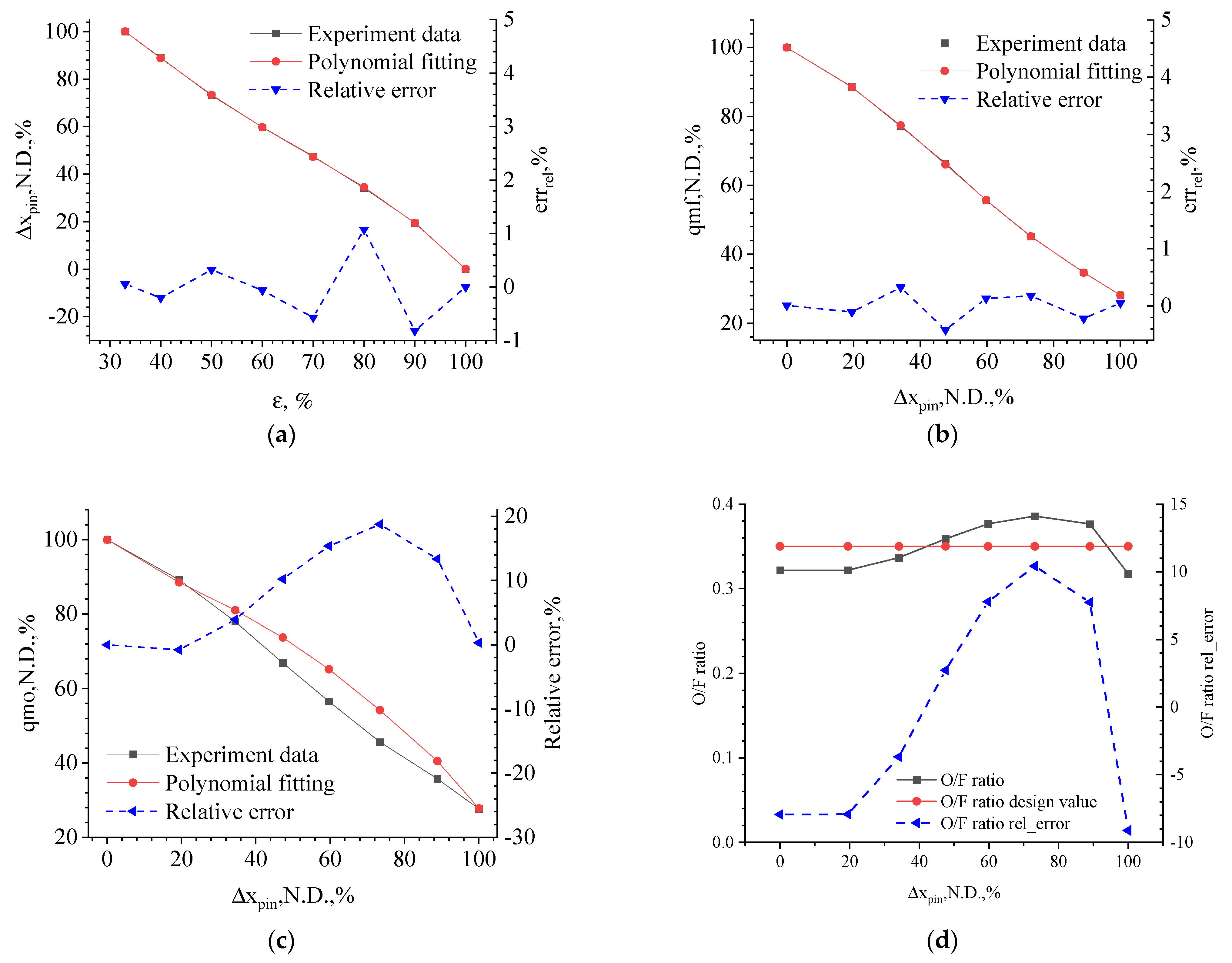
3.1. Experimental Research on Steady-State Regulation Characteristics

Experiments were carried out in order to verify the proposed method of thrust control based on IFRGG line displacement closed-loop control. The test system was composed of an engine controller, IFRGG, simulated flight control system, PWM high-speed solenoid valve, LVDT line displacement sensor, pressure sensor, temperature sensor, cable, gas cylinder, DC power supply, flow meter, control valve, hand valve, etc. At the same time, the test program of the upper-computer and the flight program of the engine controller were developed, and a multi-round joint test was carried out.
The experiment facilities were built and a thrust closed-loop control test based on the pintle displacement was carried out. The working principle of the experiment facilities and the experiment process are shown in Figure 7 and Figure 8. The main working parameters of the hardware participating in the experiment are shown in Table 1.
After the set-up of the LRE variable-thrust adjustment and control experiment system, the control parameter setting test was carried out first, in order to obtain the optimal steady-state control accuracy, overshoot, and response time. The maximum data acquisition frequency was 3000 Hz, the filtering frequency was 500 Hz, the data storage frequency was 200 Hz, the control frequency was 50 Hz, and the optimized controller parameters P and I were determined after several repeated debugging tests.
On this basis, the through-flow test, flow resistance matching test, and displacement–flow regulation characteristic test were carried out. The test results are shown in Figure 9, which are all dimensionless. As shown in Figure 9a, in this test, the working factors of the variable-thrust LRE are adjusted within a range of 100~30% through pintle displacement adjustment, and the relationship between displacement and working factors is approximately linear. The square black-line and the red circle-line in Figure 9a,b are most completely coincident. This is due to an approximate linear relationship between the variable-thrust condition and displacement, so the polynomial fitting error is very small. The black square block plots in Figure 9b,c are the steady-state test results of the adjustment characteristics of the pintle displacement, fuel and oxidizer mass flow. It can be seen that, through the movement of the pintle, the fuel and oxidizer flow can be adjusted in a range of 100%~30% to meet the demand of variable thrust. The relationship between the displacement and fuel and oxidizer flows is approximately linear. The oxidizer/fuel mixing ratio of the IFRGG can be further obtained from the test results in Figure 9b,c. As mentioned earlier in this paper, the oxidizer and fuel flow area of IFRGG under each variable-thrust condition is determined in the design stage. In the actual work process, the change of the two flow areas can be realized synchronously by changing the control variable, i.e., the pintle displacement. In the flow regulation characteristic test stage, two tests are conducted to obtain a corresponding relationship between fuel flow and pintle displacement and a corresponding relationship between oxidant flow and pintle displacement. Both the corresponding relationship between oxidant flows to displacement and that between fuel flows to displacement are almost linear. However, since only one control variable (displacement) can be used to control two controlled variables (two flow areas), as shown in the oxidizer flow chart in Figure 9c, the abscissa can only use the displacement data in the fuel flow displacement test, so the oxidizer flow fuel is not completely corresponding. It can be seen that when adjusting the working condition (by changing the pintle displacement), the oxidizer/fuel mixing ratio is distributed around the design value of 0.35, and the deviation from the design value is no more than ±10%. Considering that factors affecting turbine power capacity include the gas mass flow rate, gas constant, and gas temperature, adaptive adjustment can be carried out to a certain extent. Therefore, the influence of the O/F mixing ratio deviation is small and within an acceptable range.
According to the steady-state test data of the regulation characteristics, the polynomial fitting method is adopted to obtain the specific forms of the f u n q m f and f u n q m o functions, as shown in Equations (21) and (22), and they are both a vector product of a row vector and a column vector.
q m f ( x p i n ) = P q m f × [ x p i n 5 , x p i n 4 , x p i n 3 , x p i n 2 , x p i n , 1 ] T
q m o ( x p i n ) = P q m o × [ x p i n 6 , x p i n 5 , x p i n 4 , x p i n 3 , x p i n 2 , x p i n , 1 ] T
where
P q m f = [ 882.57 ,   1648 , 686.95 , 180.07 , 230.75 ,   377.3 ]
P q m o = [ 3824 ,   9146.9 , 8074.3 ,   3115.6 , 497.68 , 59.624 ,   121.36 ]
Furthermore, unit of q m f , q m o is kg/s, unit of x p i n is mm, and the polynomial P q m f and P q m o vectors are dimensionless.
The fitting results of Equations (21) and (22) are also shown in Figure 9. As can be seen from the red dot-figure in Figure 9b, the deviation between the fitting results of displacements and fuel flow steady-state regulation characteristics and the test data is less than ±0.5%, which can sufficiently meet the data processing and transmission requirements of the control system. It can be seen in Figure 9c that the fitting results of the displacement–oxidizer flow steady-state regulation characteristics deviate from the test data. This is because only the displacement of the same control quantity can realize the control of the fuel flow and oxidizer flow at the same time, and there are large machining tolerances and mating tolerances in the process of fuel and oxidizer circular joint structure processing and mating installation. In order to obtain more reasonable flow resistance characteristics, repeated debugging tests are needed. Therefore, the displacement–fuel flow regulation characteristics and displacement–oxidizer flow regulation characteristics are not obtained in the same test, but in the fuel characteristic test and oxidizer characteristic test, respectively, so it is difficult to align the displacement reference. Therefore, the fitting curve in Figure 9c above is drawn on the horizontal coordinate of the displacement in Figure 9b, which is also the adjustment characteristic of the real control system, which also explains the phenomenon of the large deviation of the O/F mixing ratio in Figure 9d.

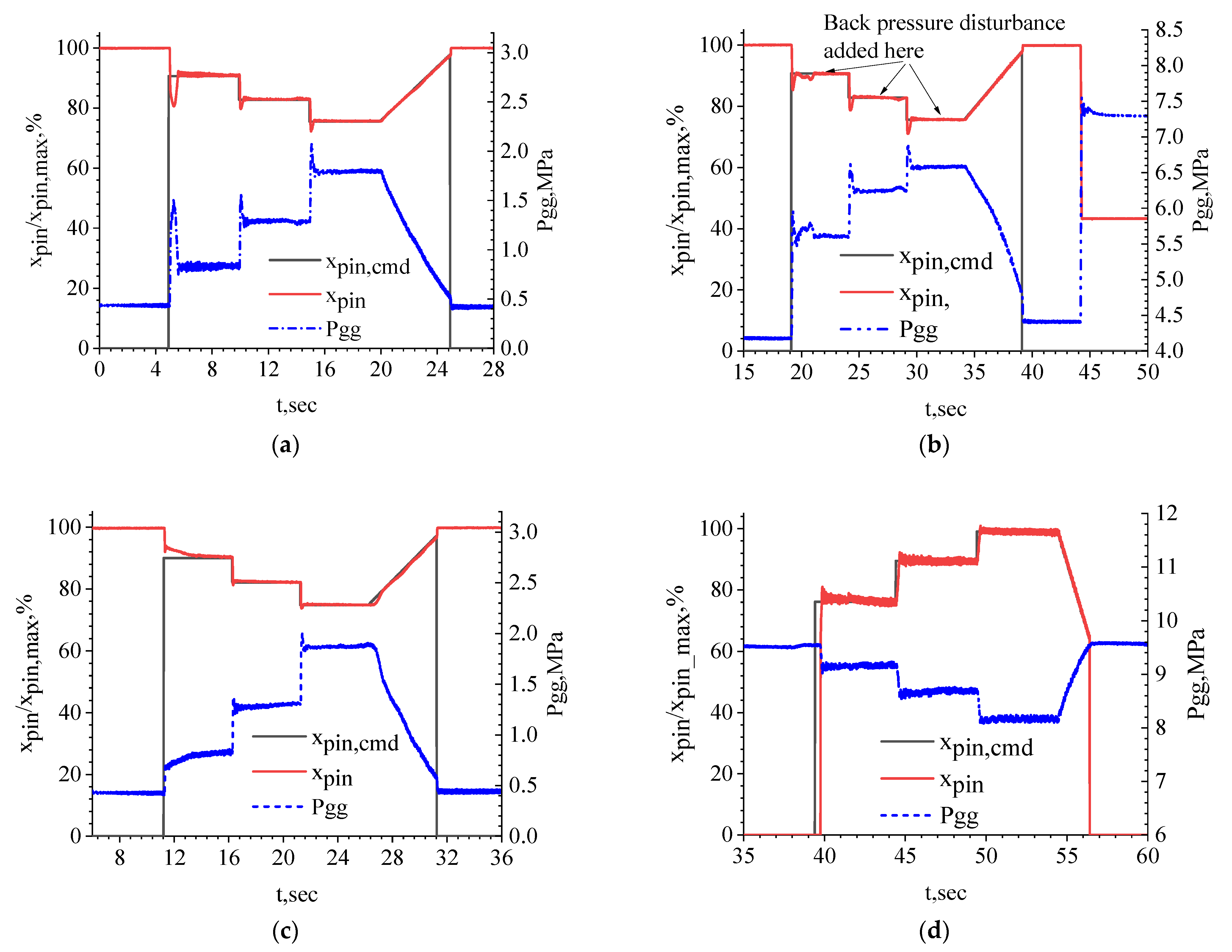
3.2. Experimental Research on Variable-Thrust Control System

According to the flow regulation characteristics of the IFRGG, several displacement closed-loop control tests were carried out. In this paper, four representative test results numbered as XC-001, XC-002, XC-003, and XC-004 were selected for display and analysis. The inlet control pressure of XC-001 and XC-002 was 6.8 MPa, and that of XC-003 and XC-004 was 4.5 MPa. The electric area-adjustable orifice area was A3 for XC-001 and XC-002, A5 for XC-003, and A6 for XC-004, which have been illustrated in Figure 3. The curves of the four tests are shown in Figure 10.
In order to prevent the phenomenon whereby the pintle cannot move at a suitable speed due to an excessive load, a higher inlet control pressure of 6.8 MPa was selected in the first test, as well as a smaller electric area-adjustable orifice area, i.e., A3. These measures were intended to increase the force of the actuator. According to the XC-001 test data in Figure 10a, the delay and overshoot of the first displacement step control are both large, and the system only has one overshoot. This indicates that there is a large static friction force in the initial state which causes the system to have a large time delay phenomenon. A summary of control system performance including overshoot, adjustment time, and steady state error has been given in Table 2.
Generally, at the first test in a day, as the moving part pintle and the sleeve are in a static friction state, a larger actuator force is required to overcome it. When the control process is going onto the second step, the system is in a dynamic equilibrium state, and the friction is kinetic. In addition, after several tests have been carried out on the same day, the friction force will be very small in the following test, so some graphs have a large overshoot, and others have no overshoot.
After the direction of friction is changed, the system starts to adjust in the opposite direction and rapidly converges to the set value, gradually stabilizing near the set value. When the system is in a dynamic equilibrium state, another instruction value can be reset, and the system can quickly converge. When the slope instruction, which is mainly used to simulate some situations of slowly varying thrust, is used, the system has no overshoot because the instruction changes slowly. Additionally, the control system has good tracking performance and almost no steady-state error. The blue dotted line in Figure 10 is the chamber pressure curve, and it is easy to see that the chamber pressure, which is seen as being representative for thrust, can also achieve good tracking. Thus, the test results clearly verify that the method of real-time displacement measurement and closed-loop control can effectively achieve variable-thrust control. The larger chamber pressure overshoot in Figure 10 is caused by the larger force of the actuator.
Figure 10b shows the test results of XC-002 at identical test conditions as for XC-001. In order to verify the anti-interference ability of the control system under a large back-pressure disturbance, the back-pressure disturbance was automatically added by an electric back pressure value in the XC-002 tests. According to the test results, with the superposition of the disturbance quantity, the displacement control produces a certain fluctuation, but after a certain time correction, the displacement can still return to the command value. This shows that the control system has excellent anti-interference ability.
Considering the larger overshoot of the chamber pressure in the XC-001 and XC-002 tests due to the large control pressure at the actuator inlet, the inlet control pressure was reduced from 6.8 MPa to 4.5 MPa, and the area of the electric area-adjustable orifice was increased to A5. The test results are shown in Figure 10c. It is easy to see that the overshoot and steady-state error of the displacement control are significantly reduced, but the displacement tracking is slow in the first-step control, which indicates that the force in the control chamber is too low, and that on the piston surface is insufficient. The chamber pressure, equivalent to thrust, has a good response process under different working conditions, and the overshoot is almost eliminated. However, similar to the displacement response, the first-step control also has the phenomena of a fixed steady-state error and a slow response time caused by the insufficient force.
After the XC-003 test, the area of the electric area-adjustable orifice was further increased to A6, and the test was repeated. XC-004 tests were then carried out for a low working condition to a high working condition. The test results are shown in Figure 10d. This experiment not only verifies the variable-thrust control ability from a high working condition to a low working condition, but also determines the better control chamber pressure and electric area-adjustable orifice area parameters. As can be seen in Figure 10d, the displacement tracking is good, the chamber pressure response is fast, the overshoot is small, and the variable-thrust control effect is good. There always exists a high-frequency and small-amplitude fluctuation (defined as the instantaneous value of a time-series parameter that does not coincide with its steady-state value) in the working parameter, such as pressure, flow rate, and displacement, which is caused by the friction between the pintle and the sleeve. In fact, the existence of friction ensures the flexible and reliable movement of the pintle. Too little friction will lead to difficulty in controlling the system, and too much friction will lead to the stagnation of the moving parts.
The authors are developing an 80t-thrust variable thrust rocket engine, and the research results of this paper are only part of an intermediate state, which will soon be applied in the integration demonstration flight experiment of the of the 80 ton variable thrust rocket engine.

4. Conclusions

In this paper, under the current urgent demand for reusable launch rockets and variable-thrust LRE technology research, a high-precision variable-thrust control method based on the real-time measurement of pintle displacement and closed-loop feedback control was proposed to solve the technical problems of the wide-range variable-thrust control of pintle LRE. The dynamic model of the variable-thrust control system was established, and the design and simulation of this system have been performed. The experimental verification of the variable-thrust control method was carried out, and the control system characteristics of the LRE in the process of variable thrust were obtained. The feasibility of the variable-thrust control method was verified.
IFRGG has two very narrow annular gaps and several grooves on the plug, and the structure profile of the annular gap is appropriately designed. By an axial linear movement of the pintle, the flow area of the two gaps can be changed under different variable-thrust conditions; when an appropriately accurate structure profile of the IFRGG is designed, the method based on real-time measurement of pintle displacement and closed-loop feedback control can be adopted to avoid the difficult problem of the direct measurement of the combustion pressure. This provides a correct and reasonable working principle, and the engine control system is simple. Under this method, the total change in the displacement is relatively small, generally not more than 2.0~3.0 mm, which makes it convenient for structure designers because of the impact of such a short distance movement. Under the condition of definite structural parameters, the parameters affecting the characteristics of the control system mainly include the inlet pressure of the controller, the area of the electric area-adjustable orifice, the control frequency of the PWM valve, the duty cycle, and the control parameters of the engine controller. In this paper, by carrying out experiments, the optimal control chamber pressure was determined to be 4.5 MPa, the throttling area of the electric area-adjustable orifice was A3~A6, and the control frequency was 50 Hz. With different PWM valve control duty ratios, the closed-loop displacement control requirements of high precision and fast response under different working conditions were realized, and the displacement response speed, overshoot, and steady-state control accuracy meet the requirements. The inlet control pressure has a great influence on the performance index of the control system. The higher the inlet pressure, the faster the response speed of the control system and the smaller the steady-state error, but the larger the overshoot. On the contrary, with a lower inlet pressure, the overshoot of the control system decreases significantly, but the response speed slows down and the steady-state error increases. According to the test results, the steady-state error of the control system is at 0.31~0.97%, the chamber pressure response time is not more than 0.3 s, the overshoot is not more than ±3%, and the pulsation amplitude is not more than ±5%, which solves the problem of the wide-range thrust adjustment and control of variable-thrust LRE of reusable launch rockets.
In the next step, the control method will be applied to the flight experiment of a Reusable launch rocket in China, which will provide important support for rocket recovery and reuse and a significant reduction in launching costs. The authors are developing an 80t-thrust variable thrust rocket engine, and the research results of this paper are only part of a larger study, which will soon be applied in the integration demonstration flight experiment of the of the 80 ton variable thrust rocket engine.

Author Contributions

Conceptualization, Z.Y.; methodology, Z.Y. and Y.Q.; software, Z.Y.; validation, Z.Y.; formal analysis, Z.Y. and Y.Q.; investigation, Z.Y. and Y.Q.; resources, Z.Y., T.Z. and W.B.; data curation, Z.Y.; writing-original draft preparation, Z.Y. and Y.Q.; writing-review and editing, T.Z. and W.B.; visualization, Z.Y.; supervision, T.Z.; project administration, W.B.; funding acquisition, Z.Y. and W.B. All authors have read and agreed to the published version of the manuscript.

Funding

The authors would like to thank the China Central University Basic Scientific Research Fund for the financial support to carry out this research. The project name is “Research on control technology of 10:1 advanced variable thrust liquid oxygen kerosene engine for reusable launch rocket”, under grant number NP2022409.

Data Availability Statement

The authors confirm that all of the simulation data and experimental data selected in this paper are available without academic dispute.

Conflicts of Interest

The authors declare no conflict of interest.

References

  1. Zhang, Y.-L. State-space analysis of the dynamic characteristics of a variable thrust liquid propellant rocket engine. Acta Astronaut. 1984, 11, 535–541. [Google Scholar] [CrossRef]
  2. Doherty, M.; Gaby, J.; Salerno, L.; Sutherlin, S. Cryogenic Fluid Management Technology for Moon and Mars Missions. In Proceedings of the AIAA Space 2009 Conference & Exposition, Pasadena, CA, USA, 14–17 September 2009. [Google Scholar] [CrossRef] [Green Version]
  3. Dressler, G. Summary of Deep Throttling Rocket Engines with Emphasis on Apollo LMDE. In Proceedings of the 42nd AIAA/ASME/SAE/ASEE Joint Propulsion Conference & Exhibit, Sacramento, CA, USA, 9–12 July 2006. [Google Scholar] [CrossRef]
  4. Bazarov, V. Throttleable liquid propellant engines swirl injectors for deep smooth thrust variations. In Proceedings of the 30th Joint Propulsion Conference and Exhibit, Indianapolis, IN, USA, 27–29 June 1994. [Google Scholar] [CrossRef]
  5. Yue, C.; Li, J.; Hou, X.; Feng, X.; Yang, S. Summarization on variable liquid thrust rocket engines. Sci. China Technol. Sci. 2009, 52, 2918–2923. [Google Scholar] [CrossRef]
  6. Gilroy, R.; Sackheim, R. The lunar module descent engine—A historical summary. In Proceedings of the 25th AIAA/ASME/SAE/ASEE Joint Propulsion Conference, Monterey, CA, USA, 10–12 July 1989. [Google Scholar] [CrossRef]
  7. Elverum, J.G.; Hoffman, A.; Miller, J.; Rockow, R. The descent engine for the lunar module. In Proceedings of the 3rd Propulsion Joint Specialist Conference, Washington, DC, USA, 17–21 July 1967; p. 521. [Google Scholar]
  8. Carey, L.; Buffalo, N.Y. Dual-mode, 100–101 thrust modulation rocket engine. J. Spacecr. Rocket. 1968, 5, 168–172. [Google Scholar] [CrossRef]
  9. Zhang, R.; Lan, X.; Chen, W.; Lei, J. The development of 7500 N variable thrust engine for Chang’E-3. Sci. Sin. Technol. 2014, 44, 569–575. [Google Scholar] [CrossRef]
  10. Jin, G.; Cao, W.; Chen, J.; Wang, R.; Liu, F.; Wei, Y. Key technologies and flight performance analysis for Chang’E-3 lunar lander propulsion system. Sci. Sin. Technol. 2014, 44, 385–390. [Google Scholar] [CrossRef]
  11. Strunz, R.; Herrmann, J.W. Reliability as an Independent Variable Applied to Liquid Rocket Engine Hot Fire Test Plans. J. Propuls. Power 2011, 27, 1032–1044. [Google Scholar] [CrossRef]
  12. Son, M.; Radhakrishnan, K.; Yoon, Y.; Koo, J. Numerical study on the combustion characteristics of a fuel-centered pintle injector for methane rocket engines. Acta Astronaut. 2017, 135, 139–149. [Google Scholar] [CrossRef]
  13. Song, W.; Hwang, J.; Koo, J. Atomization of gelled kerosene by multi-hole pintle injector for rocket engines. Fuel 2021, 285, 119212. [Google Scholar] [CrossRef]
  14. Lee, S.; Koo, J.; Yoon, Y. Effects of skip distance on the spray characteristics of a pintle injector. Acta Astronaut. 2021, 178, 471–480. [Google Scholar] [CrossRef]
  15. Son, M.; Lee, K.; Koo, J. Characteristics of anchoring locations and angles for GOX/GCH4 flames of an annular pintle injector. Acta Astronaut. 2020, 177, 707–713. [Google Scholar] [CrossRef]
  16. Yu, N.; Zhou, C.; Cai, G.; Wang, J. 2.5 kN pump-pressure pintle engine ignition experiment in different loading cases. Aerosp. Sci. Technol. 2022, 127, 107732. [Google Scholar] [CrossRef]
  17. Zhao, F.; Zhang, H.; Zhang, H.; Bai, B.; Zhao, L. Review of atomization and mixing characteristics of pintle injectors. Acta Astronaut. 2022, 200, 400–419. [Google Scholar] [CrossRef]
  18. Kang, D.; Han, S.; Ryu, C.; Ko, Y. Design of pintle injector using Kerosene-LOx as propellant and solving the problem of pintle tip thermal damage in hot firing test. Acta Astronaut. 2022, 201, 48–58. [Google Scholar] [CrossRef]
  19. Dressler, G.A.; Martin Bauer, J. TRW Pintle Engine Heritage and Performance Characteristics. In Proceedings of the 36th AIAA/ASME/SAE/ASEE Joint Propulsion Conference and Exhibit 2000, 16–19 July 2000, AIAA 2000-3871. Available online: http://www.rocket-propulsion.info/resources/articles/TRW_PINTLE_ENGINE.pdf (accessed on 24 July 2000).
  20. Zhang, B.; Li, P.; Wang, K.; Yang, B. Review on pintle injector of throttling liquid rocket engine. J. Astronaut. 2020, 41, 1481–1489. (In Chinese) [Google Scholar]
  21. Li, J.; Yue, C.; Hou, X.; Feng, X. Numerical simulation of inner Flow field of a pintle Injector variable thrust rocket engine. Comput. Simul. 2009, 26, 49–52, 88. [Google Scholar]
  22. Huang, X.; Huang, M.; Hu, X. Frequency response characteristics of variable thrust engine with gas generator cycle. J. Rocket. Propuls. 2020, 46, 29–35. [Google Scholar]
  23. Jin, Y.; Xu, X.; Zhu, S.; Xiang, L. Design and test of 15:1 GO2/kerosene variable-thrust rocket engine. J. Propuls. Technol. 2018, 39, 2438–2445. [Google Scholar]
  24. Casiano, M.J.; Hulka, J.R.; Yang, V. Liquid-Propellant Rocket Engine Throttling: A Comprehensive Review. J. Propuls. Power 2010, 26, 897–923. [Google Scholar] [CrossRef] [Green Version]
  25. Cardullo, M.W. Variable-Thrust Rocket Engines and Their Modes of Operation. J. Aerosp. Sci. 1960, 27, 793–795. [Google Scholar] [CrossRef]
  26. Liu, D.; Huang, S.; Zhou, W. System study of deep throttling descent rocket engine for lunar lander. J. Rocket. Propuls. 2014, 4, 22–28. [Google Scholar]
  27. Betts, E.; Frederick, R. A Historical Systems Study of Liquid Rocket Engine Throttling Capabilities. In Proceedings of the 46th AIAA/ASME/SAE/ASEE Joint Propulsion Conference & Exhibit, Nashville, TN, USA, 25–28 July 2010. [Google Scholar] [CrossRef]
  28. Norris, J.D.; Vernon, D.W. Apollo propulsion-system performance evaluation. In Proceedings of the 4th Propulsion Joint Specialist Conference, Cleveland, OH, USA, 10–14 June 1968. [Google Scholar]
  29. Ono, D.; Dressler, G.; Kruse, W.; Solbes, A. The design, development, and qualification of an advanced columbium liquid apogee engine(Ac-Lae). In Proceedings of the 34th AIAA/ASME/SAE/ASEE Joint Propulsion Conference and Exhibit, Cleveland, OH, USA, 13–15 July 1998. [Google Scholar]
  30. Naderi, M.; Karimi, H.; Guozhu, L. Modeling the effect of reusability on the performance of an existing LPRE. Acta Astronaut. 2021, 181, 201–216. [Google Scholar] [CrossRef]
  31. Giuliano, V.; Leonard, T.; Lyda, R.; Kim, T. CECE: Expanding the Envelope of Deep Throttling in Liquid Oxygen/Liquid Hydrogen Rocket Engines For NASA Exploration Missions. In Proceedings of the 46th AIAA/ASME/SAE/ASEE Joint Propulsion Conference & Exhibit, Nashville, TN, USA, 25–28 July 2010. [Google Scholar] [CrossRef] [Green Version]
  32. Giuliano, V.; Leonard, T.; Adamski, W.; Kim, T. CECE: A deep throttling demonstrator cryogenic engine for NASA’s lunar lander. In Proceedings of the 43rd AIAA/ASME/SAE/ASEE Joint Propulsion Conference & Exhibit, Cincinnati, OH, USA, 8–11 July 2007; p. 5480. [Google Scholar]
  33. Tsutsumi, S.; Hirabayashi, M.; Sato, D.; Kawatsu, K.; Sato, M.; Kimura, T.; Hashimoto, T.; Abe, M. Data-driven fault detection in a reusable rocket engine using bivariate time-series analysis. Acta Astronaut. 2021, 179, 685–694. [Google Scholar] [CrossRef]
  34. Li, Y.; Fang, J.; Sun, B.; Li, K.; Cai, G. Index allocation for a reusable LOX/CH4 rocket engine. Chin. J. Aeronaut. 2021, 34, 432–440. [Google Scholar] [CrossRef]
  35. Jo, B.-U.; Ahn, J. Optimal staging of reusable launch vehicles for minimum life cycle cost. Aerosp. Sci. Technol. 2022, 127, 107703. [Google Scholar] [CrossRef]
  36. Sippel, M.; Stappert, S.; Koch, A. Assessment of multiple mission reusable launch vehicles. J. Space Saf. Eng. 2019, 6, 165–180. [Google Scholar] [CrossRef] [Green Version]
  37. Koelle, D. The cost-optimal size of future reusable launch vehicles. Acta Astronaut. 2000, 47, 205–213. [Google Scholar] [CrossRef]
  38. Marks, P. SpaceX’s explosive start. New Sci. 2021, 249, 30. [Google Scholar] [CrossRef]
  39. Murchie, S.; Eng, D.; Chabot, N.; Guo, Y.; Arvidson, R.; Yen, A.; Trebi-Ollennu, A.; Seelos, F.; Adams, E.; Fountain, G. MERLIN: Mars-Moon Exploration, Reconnaissance and Landed Investigation. Acta Astronaut. 2014, 93, 475–482. [Google Scholar] [CrossRef]
  40. Zhou, X. The Analysis for Regulation Performance of a Variable Thrust Rocket Engine Control System (Journal article). Chin. J. Astronaut. 1982, 1, 18–29. Available online: https://en.cnki.com.cn/Article_en/CJFDTOTAL-YHXB198201001.htm (accessed on 18 October 2022).
  41. Feng, X.; Zhang, Y.; Chen, Q. A digital controller for variable thrust liquid rocket engines. In Proceedings of the 29th Joint Propulsion Conference and Exhibit, Monterey, CA, USA, 28–30 June 1993. [Google Scholar] [CrossRef]
  42. Cui, P.; Li, Q.; Cheng, P.; Chen, L. System scheme design for LOX/LCH4 variable thrust liquid rocket engines using motor pump. Acta Astronaut. 2020, 171, 139–150. [Google Scholar] [CrossRef]
  43. Cui, P.; Li, Q.; Cheng, P.; Zhang, B. A comparative study of system schemes for LOX/LCH4 expander cycle liquid rocket engine. J. Natl. Univ. Def. Technol. 2020, 42, 106–115. [Google Scholar]
  44. Liang, T.; Song, J.; Li, Q.; Cui, P.; Cheng, P.; Chen, L. System scheme design of electric expander cycle for LOX/LCH4 variable thrust liquid rocket engine. Acta Astronaut. 2021, 186, 451–464. [Google Scholar] [CrossRef]
  45. Song, J.; Liang, T.; Li, Q.; Cheng, P.; Zhang, D.; Cui, P.; Sun, J. Study on the heat transfer characteristics of regenerative cooling for LOX/LCH4 variable thrust rocket engine. Case Stud. Therm. Eng. 2021, 28, 101664. [Google Scholar] [CrossRef]
  46. Tournes, C.H.; Reimonte, P.A.; Shtessel, Y. Throttling of Liquid Rockets using Higher Order Sliding Mode Control. In Proceedings of the 50th AIAA/ASME/SAE/ASEE Joint Propulsion Conference, Cleveland, OH, USA, 28–30 July 2014. [Google Scholar] [CrossRef]
  47. Cheng, P.; Li, Q.; Wu, J.; Kang, Z. Dynamic Response of a Dual-Manifold Injector Rocket Engine to Throttling. J. Propuls. Power 2018, 34, 1553–1560. [Google Scholar] [CrossRef]
  48. Shieber, H.; Rupert, R.C. Assurance of service life of the Mira 150A variable thrust rocket engine. J. Spacecr. Rocket. 1966, 3, 1034–1038. [Google Scholar] [CrossRef]
  49. Boyd, B.R.; Johnson, R.J.; Smith, T.H. Application of the Mira 150A variable-thrust engine to manned lunar flying systems. J. Spacecr. Rocket. 1968, 5, 849–851. [Google Scholar] [CrossRef]
  50. Gore, M.R.; Carroll, J.J.; Gore, J.J.C.M.R. Dynamics of a Variable Thrust, Pump Fed, Bipropellant, Liquid Rocket Engine System. J. Jet Propuls. 1957, 27, 35–43. [Google Scholar] [CrossRef]
  51. Rahn, D.; Haidn, O.; Riedmann, H. Timescale-Based Frozen Nonadiabatic Flamelet Combustion Modeling for Rocket Engine Thrust Chambers. J. Propuls. Power 2021, 37, 495–508. [Google Scholar] [CrossRef]
Figure 1. Working schematic of a mechanical positioning scheme of an MIRA-10K series engine.
Aerospace 10 00032 g001
Figure 2. Working principle of the variable-thrust LRE IFRGG.
Aerospace 10 00032 g002
Figure 3. Regulation characteristics of the IFRGG. (a) τPWM at Pic = 4.5 MPa. (b) τPWM at Pic = 6.8 MPa.
Aerospace 10 00032 g003
Figure 4. Steady-state operating characteristics of the IFRGG. (a) ε-xpin steady-state relationship. (b) xpin-qm steady-state relationship. (c) xpin-Pif/Pio/Pgg steady-state relationship. (d) xpin-PcPWM steady-state relationship.
Aerospace 10 00032 g004
Figure 5. Variable-thrust control system scheme.
Aerospace 10 00032 g005
Figure 6. Simulation results of the control system based on displacement closed-loop control. (a) Displacement instruction and tracking results. (b) Chamber pressure control results.
Aerospace 10 00032 g006
Figure 7. The working principle of experiment facilities.
Aerospace 10 00032 g007
Figure 8. The experiment facilities and process.
Aerospace 10 00032 g008
Figure 9. Experimental results of displacement–flow regulation characteristics of the IFRGG. (a) Working condition factor-displacement. (b) Displacement-fuel flow. (c) Displacement-oxidizer flow. (d) O/F ratio and its deviation.
Aerospace 10 00032 g009
Figure 10. Test results of the variable-thrust control system. (a) XC-001. (b) XC-002. (c) XC-003. (d) XC-004.
Aerospace 10 00032 g010
Table 1. The main working parameters of the hardware participating in the experiment.
S.NHardware NameCodeSpecificationsElectrical Characteristics
1PWM valvePWMEquivalent diameter 0.4 mmVoltage 27 ± 3 V, Resistance 39 Ω,
Response time 4~6 ms
2Back pressure sensorPggpressure: 2~8 MPa;
temperature: 100~200 °C;
Precision: 1% F.S (25 + 10); Excitation voltage: 10~15 VDC; Zero point output: 0.2 ± 0.1 V; Zero drift: 0.25% F.S (1/2 h); Full range output: 4.8 ± 0.1 V; Power supply current: ≤20 mA; Absolute point resistance: ≥100 MΩ
3Servo chamber pressure sensorPcpressure: 0~11 MPa;
temperature: −25~25 °C;
Input 15 ± 2 V; Output 0.5~4.5 V
4Pgg pressure sensorXpinLinear displacement 2.0 mmInput 24~28 VDC; Output 0~5 V
5Integrated flow regulator/gas generator
Table 2. Summary of control system performance.
S. No.Test CodeTest ConditionsOvershoot, %Adjustment Time, sSteady State Error, %
1XC-001Pc = 6.8 MPa,
AOR = A3
4.350.110.35
2XC-002Pc = 6.8 MPa,
AOR = A3
6.090.070.31
3XC-003Pc = 4.5 MPa,
AOR = A5
1.500.100.35
4XC-004Pc = 4.5 MPa,
AOR = A6
1.920.180.97
Disclaimer/Publisher’s Note: The statements, opinions and data contained in all publications are solely those of the individual author(s) and contributor(s) and not of MDPI and/or the editor(s). MDPI and/or the editor(s) disclaim responsibility for any injury to people or property resulting from any ideas, methods, instructions or products referred to in the content.

