
Experimental Proof of Concept of a Noncircular Rotating Detonation Engine (RDE) for Propulsion Applications

Department of Aerospace Engineering, Pusan National University, Busan 46241, Republic of Korea
*
Author to whom correspondence should be addressed.
Aerospace 2023, 10(1), 27; https://doi.org/10.3390/aerospace10010027
Submission received: 12 December 2022
/
Revised: 23 December 2022
/
Accepted: 25 December 2022
/
Published: 28 December 2022
(This article belongs to the Special Issue Fundamental Detonation Mechanism and Advanced Detonation Propulsion Technology)
Abstract
:A noncircular engine cross-section could provide great flexibility in the integration of propulsion into the airframe. In this work, a tri-arc RDE was constructed and tested as an example of noncircular cross-sectioned RDE. The operational characteristics of detonation wave propagation and thrust performance were investigated and compared with an equivalent circular RDE under the same operating conditions. High-speed camera images, short-time Fourier transform (STFT), and fast Fourier transform (FFT) were used for the investigation. The tri-arc RDE showed very similar characteristics to the circular RDE but exhibited slightly better stability and propulsion performance than the circular RDE. We consider that repeated curvature changes positively affect the stability of detonation wave propagation. The experimental data show contradicting results from the numerical analysis with a homogeneous mixture assumption in which the detonation pressures at the convex corner were greater than those at the concave corner. It is reasoned that the tri-arc injector design provides a non-uniform mixture composition, resulting in a strong detonation at the convex corner. Overall, the noncircular RDE of a tri-arc shaped cross-section is demonstrated, one which performs slightly better than an ordinary circular-shaped RDE both in detonation stability and performance.
1. Introduction
Research on detonation-based propulsion for the realization of a pressure gain combustion (PGC) device has been actively carried out over the last two decades. Among recent advances, the rotating detonation engine (RDE) has been researched worldwide due to its advantages such as an additional compression effect, high thermal efficiency, and simplicity of operation, all of which lead to a detonation that propagates continuously through the annular channel once initiated.
However, there is another advantage of RDE that has not been well conceived. Since the RDE is a sort of combustor, there are no rotating parts, such as a compressor or turbine. Instead, there is only the detonation wave as it moves continuously along the annular channel. Therefore, the combustor cross-section is not necessarily circular but could be an arbitrary shape once the detonation is able to propagate stably. Such a noncircular cross-section concept has been suggested and tested through numerical simulation, as shown in Figure 1 [1]. The RDE of a noncircular cross-section could provide great flexibility in the design of the propulsion system and its integration into the airframe for the advanced requirements of things such as stealth characteristics. This would be especially true for propulsion systems where the combustor is not connected to the compressor or turbine, such as ramjet and scramjet engines. Since the circular configuration is not a mandatory geometrical constraint for RDE, but a closed-loop configuration, the noncircular geometry provides extreme design flexibility for the integration of the propulsion system into the airframe, especially for stealth characteristics or aerodynamic performance. Le Naour et al. conducted preliminary tests on a large-scale continuous detonation wave engine at the MBDA ramjet test facility, showing that the more mass flow rate and total temperature are provided, the stronger the detonation wave gets [2].
Several experimental studies have been conducted for racetrack-shaped RDEs. Gawahara et al. [3] investigated and observed basic combustion characteristics in a racetrack RDE using a high-speed camera. Wen et al. [4] investigated the propagation behaviors of rotating detonation in a racetrack RDE by measuring the pressure. Peng et al. [5], Feleo et al. [6] and Chacon and Gamba [7,8,9] used a racetrack RDE as an optically accessible combustor to visualize detonation waves. Sosa et al. used a ρ-shaped cross-section RDE and optically investigated the way in which the detonation wave tangential propagated into the combustion channel [10]. These studies were carried out to visualize detonation wave characteristics in RDE, but system-level design advantages and its characteristics have rarely been given much thought.
For rotating the detonation waves in an RDE with a noncircular cross-section, an important design point is the radius of curvature for which the detonations can propagate stably. Choi et al. [1,11] investigated the effects of curvature on the detonation propagation in 2D channels and showed that the critical radius of curvature is less than r⁄H = 3.0. It is known from a previous study that the detonation wave propagates unstably or is overdriven when the radius of curvature is smaller than the critical radius. Stability characteristics for the small radius of curvatures have been studied and confirmed both experimentally and numerically by several studies. Kudo et al. [12] and Nakayama et al. [13,14] experimentally and theoretically investigated the propagation characteristics of curved detonation waves in several curved channels with different radii of curvature. They showed that the critical radius of curvature for the C2H4 + O2 mixture is about rin⁄λ = 23.0 where H = 20.0 mm. Matsuo et al. [15] numerically investigated the detonation behaviors in a 2D curved channel and showed that the critical radius of curvature is about r⁄λ = 27.2 when the rout⁄rin = 1.5 and 2.0. Pan et al. [16,17] experimentally studied the propagation characteristics of the curved detonation wave in helical channels utilizing a similar configuration to the computational domain used in [1,11]. Xia et al. showed that the detonation wave steadily propagated in the combustion channel when rin + 0.464 Pa ≥ 80.932 or rin ≥ 40 mm [18]. Kawasaki et al. experimentally investigated the effect of an inner radius ranging from 0 to 31 mm and showed that the critical radius is 15 mm [19]. Katta et al. numerically and experimentally demonstrated that, as the channel width increases, the inclined detonation front is formed between walls, and the detonation wave of the outer wall becomes stronger [20]. Zhou et al. showed that, as the channel width increased, the variation in the flow field became apparent, while the detonation height and specific impulse nearly showed variation [21]. Kudo et al. showed that the critical curvature of a rectangular cross-section bent tube is 14~40-times the detonation cell width [12]. Zhao et al. numerically investigated the effect of 5-, 8-, and 12-mm channel widths and showed that the thrust and specific impulse reached their highest at 5 mm [22]. Wang et al. numerically studied the effect of corner angle at the trapezoidal cross-section and showed that the detonation wave can propagate at right, acute, and obtuse angles [23]. From these studies, it is considered that the radius of curvature is an important geometric parameter for the stable propagation of detonation waves. Therefore, it is suggested that the local radius of curvature should be greater than the critical value for designing a noncircular RDE cross-section for stable propagation of detonation wave.
Since there is neither an experimental nor a realistic numerical study for the noncircular RDE of arbitrary cross-section, an RDE of a tri-arc-shaped cross-section was designed and tested in comparison with a circular RDE as an example of a generally shaped cross-section. It is called ‘tri-arc RDE’ in this paper since it looks like a tri-lobed fidget spinner toy. Its scale is almost identical to the RDE with circular cross-sectional shape (circular RDE) conducted previously [24], except for some unavoidable mechanical discrepancies for the different shapes. The primary goal of the present study is to investigate the basic characteristics and performance of the tri-arc RDE and compare it with those of circular RDE.
2. Experimental Setup
The tri-arc RDE is designed as an uncooled device and is fabricated with stainless steel for a short time hot-fire test. The channel width and length of the tri-arc RDE follows the model of the circular RDE, which referred to the model of Hansmetzger et al. [25]. Except for the cross-sectional shape, its size and structure are similar to the circular RDE used as a reference model of tri-arc RDE, as shown in Figure 2 and Figure 3, and Table 1. The slot injector type of oxidizer and fuel are ring-type and disk-type for both RDEs. The dimensions of the tri-arc RDE are also selected closely so as to have an equivalent channel cross-section area. Therefore, a comparative discussion could be undertaken under similar conditions.
The cross-sectional shape of the tri-arc RDE consists of a tri-lobed-rounded plane of 120 degrees. The length and width of the combustion channel are 75.0 and 4.5 mm, respectively. Each size of injection slots for the fuel and oxidizer is 0.34 and 0.4 mm. The cross-sectional areas for each injection slot and combustion channel are 46.8, 63.3, and 771.4 mm2, respectively. Gaseous ethylene (GC2H4) and oxygen (GO2) are used as fuel and oxidizer, where they are injected from each plenum into the combustion channel through each injection slot, as shown in Figure 3. The dimensionless radius of curvatures of both RDEs expressed as r⁄H, is shown in Table 1.
A micro-scale pre-detonator is used for detonation initiation in the combustion channel, which shares the same fuel and oxidizer with the RDE. The inner diameter and length are about 4.2 and 150.0 mm, respectively. The Shchelkin spiral is not used in this pre-detonator since the deflagration to detonation transition (DDT) distance is sufficient for the present oxygen-based mixture. The pre-detonator is attached to the tangential direction of the RDE channel.
The pneumatic valves with solenoid valves are used as controllers and shutdown devices to control fuel and oxidizer supply. The programmable logic controller (PLC, KV-N40AT, Korea Keyence Co., Ltd., Seongnam-si, Republic of Korea) adjusts all sequences. The mass flow rate is calculated by weighing the 3.4 L gas cylinder before and after the cold flow test and is then calibrated with the measured feed pressure. The kHz pressure transducers (Keller PAA-23SY, accuracy 0.25% full scale, Keller Druckmesstechnik AG, Switzerland) are installed in each gas supply line, plenum, combustion channel, and pre-detonator, as shown in Figure 4, to measure the static pressure.
The visualization of the rotating detonation waves is taken directly by a monochrome-type high-speed camera (Phantom V2512, Phantom Inc., Wayne, NJ, USA) located 5.5 m downstream of the RDE. The thrust and impulse for comparing the tri-arc type with the circular type are obtained from the load cell (CAS SBA-100L, combined error 0.03%, CAS Scale Korea Inc., Republic of Korea), which is physically screwed to the RDE. Further experimental details can be found in a previous work [24].
The MHz pressure transducers (PCB 113B24, sensitivity 10%, PCB Piezotronics, Inc., Depew, NY, USA) are used to measure the detonation speed and investigate the characteristics of the detonation wave. They are installed at locations (p1) and (p2), designated as concave and convex corners, respectively, at the viewpoint inside the channel where the detonation wave propagates. As the sensors are exposed to thermal shock, the combination of thermal protection coating and recess mounting is applied to protect them. They are located 2.0 mm away from the channel head along the flow axis. The sensors are mounted at the surface with a recess length of 4.0 mm and a diameter of 2.0 mm to avoid the detonation wave frequencies matching with the Helm–Holtz resonance frequency of the recess cavity. The measured detonation speed is compared with the theoretical Chapman–Jouguet (CJ) detonation speed from the NASA Chemical Equilibrium with Applications (CEA) code to estimate the detonation velocity deficit.
3. Mass Flow Rate Calibration
The mass flow rate is measured and calculated within the feed pressure range of 0.2 to 0.8 MPa, as shown in Figure 5. A linear curve fitting in dashed lines shows the measured mass flow rates. The measured mass flow rates are verified by comparing them with the theoretical value for the choked condition as expressed in Equation (1).
The maximum difference from the theoretical values in the tri-arc RDE showed 1.4 g/s (6.8%) for the fuel and 1.1 g/s (3.6%) for the oxidizer. For the circular RDE, the maximum difference is 2.0 g/s (14.0%) and 3.5 g/s (9.9%), respectively. The differences are considered not so large because the mass flow rate is used to select comparable conditions for comparing the characteristics and performances of the two RDEs.
4. Experimental Procedure
The experimental procedure of the hot fire test is as follows, as shown in Figure 6 and Figure 7. The pneumatic valves open and supply oxidizer and fuel to the combustor. The response delays for both gases take up to 0.5 s (1). As the pressure of the plenum and chamber reach steady state, the spark plug ignites the pre-detonator. In the pre-detonator channel, detonation is developed through DDT (3). The detonation wave ignites the unburned gas inside the RDE chamber, and detonation waves start to develop (4). The detonation waves rotate along the combustion channel. As the detonation waves have high enthalpy and the test model is not equipped with cooling devices, the available test time is up to 0.2 s (5). The pneumatic valves of the gas supply close, and the hot fire test terminates (6). The GN2 purging gas is supplied to the channel to cool down the test model and purge the residues inside the plenum and chamber (7).
5. Operational Characteristics
Experiments were carried out for several mass flow rate conditions while the equivalence ratio, Φ, was kept close to 1.0 for the present study. Stable two-wave propagation was observed for wide-range mass flow rates, but unstable mode changes were observed for cases of small and high mass flow rates for tri-arc and circular RDEs.
5.1. Operational Characteristics at Reference Mass Flow Rate
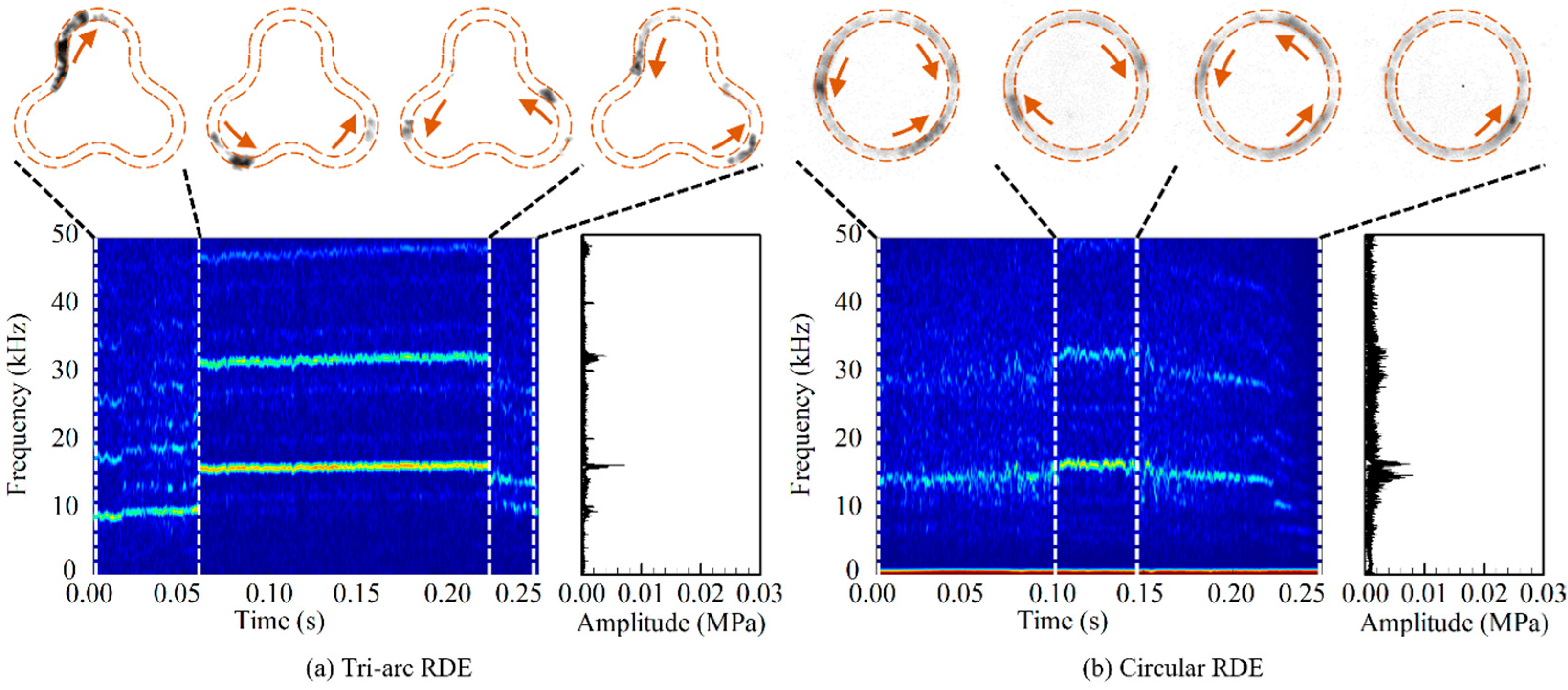
At = 80.3 g/s, both RDEs showed consistent and stable motion throughout the operation. In this study, operational characteristics of wide-range mass flow rates were compared with those of = 80.3 g/s. Figure 8 compares the two-wave detonation wave propagations in reference condition of = 80.3 g/s for tri-arc and circular RDEs. Upper is the sequential snapshots of inverted black-and-white high-speed camera images (256 × 256 resolution and 200 kfps). Short-time Fourier transform (STFT) and fast Fourier transform (FFT) results at the convex corner (p2) are plotted lower. The STFT result shows the dominant frequency-to-operation time. The contour is the amplitude which is a result of the FFT. The tri-arc and circular RDE images show the direction of the detonation waves rotating clockwise. The STFT results show that the dominant frequency and amplitude are kept steady during the operation. Dominant frequencies from FFT results are 16.72 and 17.20 kHz for tri-arc and circular RDEs, respectively.
Other mass flow rate conditions that show similar behavior to = 80.3 g/s are summarized in Table 2 for both RDEs. Depending on the equivalence ratio, CJ detonation speed ranges from 2359 to 2393 m/s. Detonation wave propagation is stable in most cases except for the circular RDE for the mass flow rate of 64.8 g/s, which shows temporarily unstable characteristics. The dominant frequency rises slightly as the mass flow rate increases while the velocity deficit reduces in both RDEs. The velocity deficit is smaller for the circular RDE at the low mass flow rate but not at high mass flow rates, though the differences between the two RDE configurations are not so big. Therefore, it is hard to conclude which configuration is better, but we consider both RDEs to have similar operation characteristics under the same conditions.
5.2. Operational Characteristics at Low Mass Flow Rate
Figure 9 shows the results for the low mass flow cases. As for the tri-arc RDE, one detonation wave stably rotates up to 0.06 s initially. After that, instability happens suddenly, and then the wave diverges into two waves rotating counterclockwise stably. The dominant frequency at stable operation is 16.68 kHz, obtained from the FFT result. However, the stable operation is not kept long beyond 0.22 s. The STFT result shows the change of operation frequency, and FFT represents the accumulation of the changing frequencies. For circular RDE, operation characteristics are rather similar, but the time for stable operation is shorter than the tri-arc RDE. High-speed images show single and multiple waves rotating clock- and counterclockwise during the unstable operation, but STFT and FFT results do not represent the dominant high frequency with strong amplitude. Therefore, we consider the detonation wave to have not fully formed during the unstable operation period.
5.3. Operational Characteristics at High Mass Flow Rate
Figure 10 shows the results for the high mass flow rate condition. The detonation wave number, defined by Wolanski [26], is 2–3 for this mass flow rate [24], while it is 2 for all other previous lower mass flow rate conditions. The tri-arc images show that two waves rotate clockwise during the operation, with the exception of a third wave which is briefly displayed. The STFT shows the three-wave period between 0.075 to 0.083 s. Frequency and amplitude maintain stability during the two- and three-wave operations; dominant frequencies of 17.78 kHz and 21.16 kHz, respectively. Unlike the tri-arc RDE, the circular RDE shows relatively unstable operation characteristics. Two waves rotate clockwise initially, but one of them changes its direction and collides. They start to turn counterclockwise and diverge into three. The STFT result shows volatile frequency and amplitude throughout the operation. The FFT result also shows dispersed frequencies around the dominant frequency. We consider this to be a transitional condition before changing to a higher detonation wave number case [24].
6. Wall Pressure Characteristics
The detonation front of the circular RDE experiences a compression effect at the outer wall and expansion at the inner wall through geometric configuration. The physics is well understood from experimental observations [12,13]. The degree of compression or expansion depends on the radius of curvature [1,11]. The local radius of curvature plays the same role for generally shaped curved channels [11]. A numerical analysis was carried out for the tri-arc RDE cross-section to find out the effect of these characteristics. To mainly focus on thermo- and fluid dynamic characteristics in the curved RDE, a simplified modeling of fluid dynamics was implemented with a one-step irreversible Arrhenius reaction model. In reaction progress, Z is introduced into the two-dimensional conservation equations of mass, momentum, and energy equations in two-dimensional coordinates for an inviscid, chemically reacting flow as expressed in Equations (2) and (3).
The governing equations are numerically solved using a cell–vertex finite-volume method. RoeM and MUSCL-TVD schemes are used to calculate convective fluxes, and the fourth order Runge–Kutta (RK4) scheme is used for time integration. The numerical code has been developed and applied for various compressible flow problems [1,11,27,28,29,30] and the combination of RoeM flux splitting and the third order MUSCL-TVD exhibits sharp shock capturing with robustness. The RK4 scheme shows the best time accurate solution while maintaining spatial accuracy. OpenMP was used to parallelize the code to maximize the computational efficiency under a multi-core SMP environment. A weakly unstable detonation condition was used from a previous study [1,16], as summarized in Table 3. The theoretical and numerical approach of a previous work [1] was used with a resolution of L1/2/∆y = 7 corresponding to 200 grid cells in channel width, which is enough for fine cell structures [27]. Slip and adiabatic boundary conditions were used for the combustor walls. Homogeneous premixed gas was assumed as natural for the present study.
The ZND structure was obtained by integrating the one-dimensional steady conservation equations with given initial conditions. Its one-dimensional steady ZND structure was stacked on to a two-dimensional curved channel for the initiation of the detonation wave. Figure 11 shows the local maximum pressure traces that show the detonation cell structures as a smoked-foil record. Low pressure region is observed at the outer wall of the convex corner caused by the expansion effect, similar to the inner wall of the circular channel. Meanwhile, a compression effect is observed at the outer wall of the concave corner caused by the compression effect similar to the outer wall of the circular channel. Figure 12 shows the pressure variation along the outer wall, which quantitatively shows the same results.
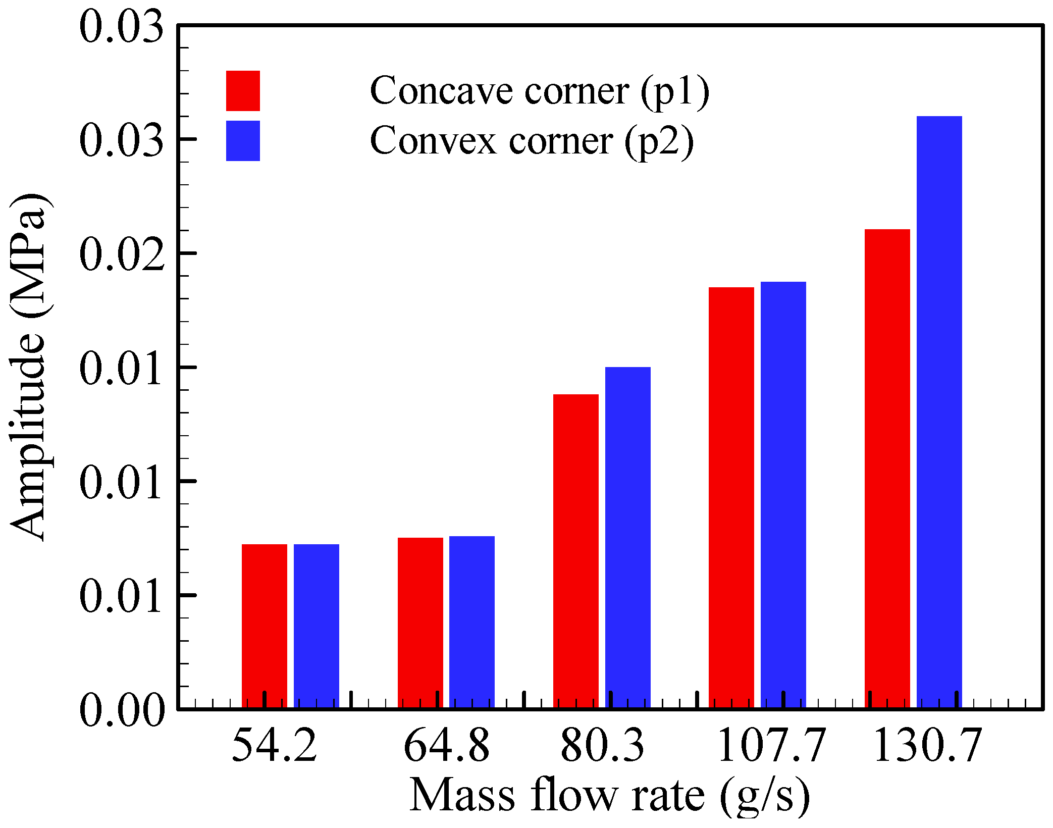
Therefore, from the theoretical and numerical perspective, the concave corner (p1) is expected to show lower pressure than the convex corner (p2). However, the experimental pressure histories exhibit contrasting results to the expectations, as shown in Figure 13. This becomes more evident from the FFT analysis, as shown in Figure 14. This result was obtained from the amplitude of the first-to-third harmonic components among the dominant amplitude of the detonation pressure. Since the actual detonation pressure is expressed as the sum of the amplitude of a large number of harmonics, these amplitudes differ from the actual pressures but are sufficient to investigate the effects of the concave and convex corners. As the mass flow rate increases, while the tendency of the amplitude change is non-uniform, the amplitude at the convex corner tends to be higher than the amplitude at the concave corner.
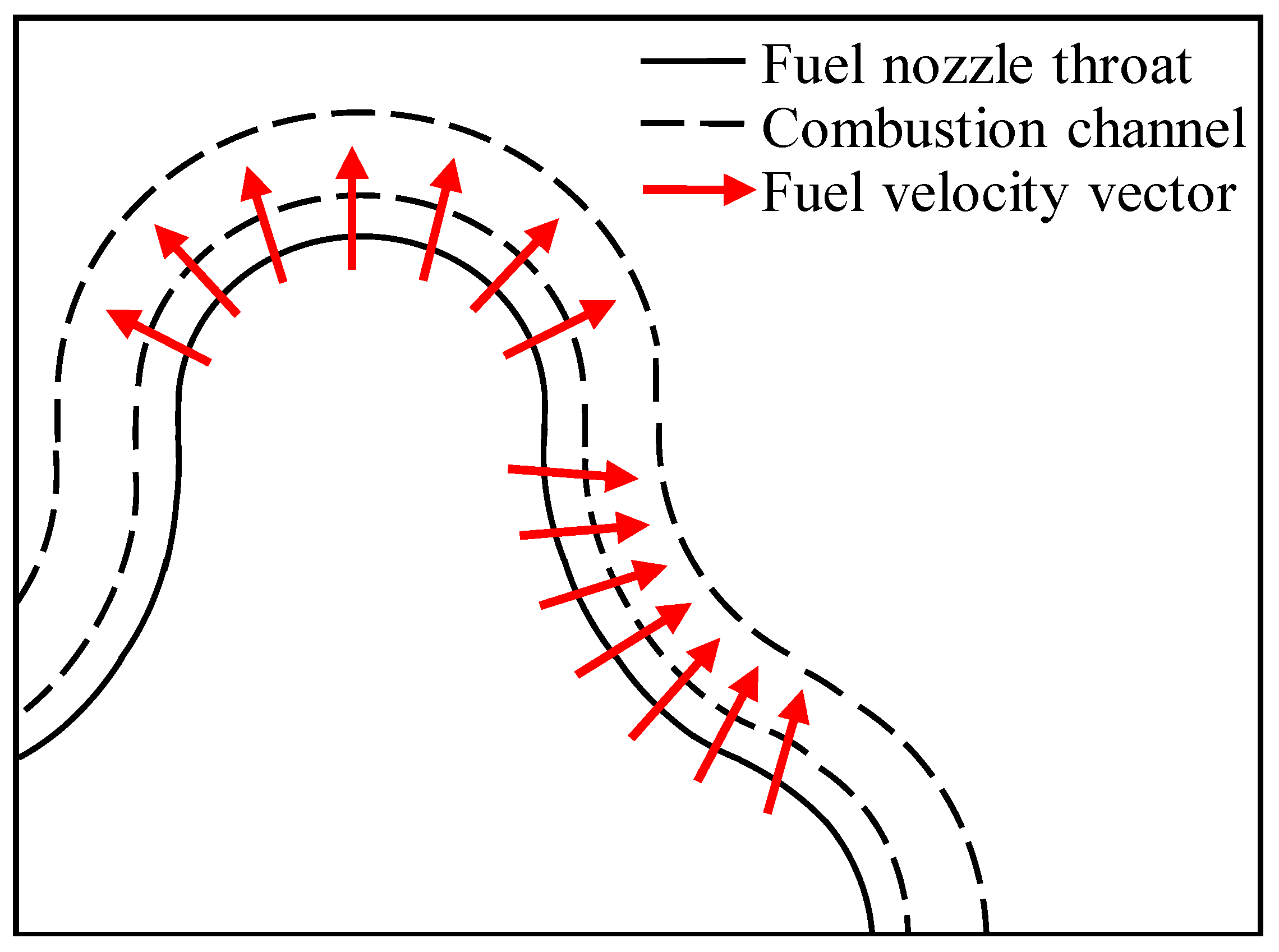
The contradictory results of numerical simulation and experimental data is presumed to be caused by the unique configuration of the tri-arc injector, as depicted in Figure 15. In the present RDE designs, the oxidizer is injected axially, while fuel is injected in a radial direction through split injectors, as shown in Figure 3. In the case of circular RDE, a homogeneous equivalence ratio could be assumed along the circumferential direction with this configuration. However, in the case of the tri-arc RDE, fuel is dispersed in the concave corner (p2), resulting in a lean mixture composition, while the fuel is relatively concentrated in the convex corner (p1), resulting in rich mixture composition. Therefore, the equivalence ratio in the tri-arc RDE channel could be non-uniform along the circumferential direction, and the high equivalence ratio condition at the convex corner (p2) could be the reason for the high-pressure data through strong detonation, contradicting the numerical analysis that assumes a homogeneous mixture. Hence, a further detailed three-dimensional simulation would be necessary to fully understand the fuel/oxidizer mixing and detonation initiation/propagation processes. Additionally, further optimization of injectors and combustors is necessary to improve the fuel/oxidizer mixing and reduce the detonation velocity deficit.
7. Thrust Performance
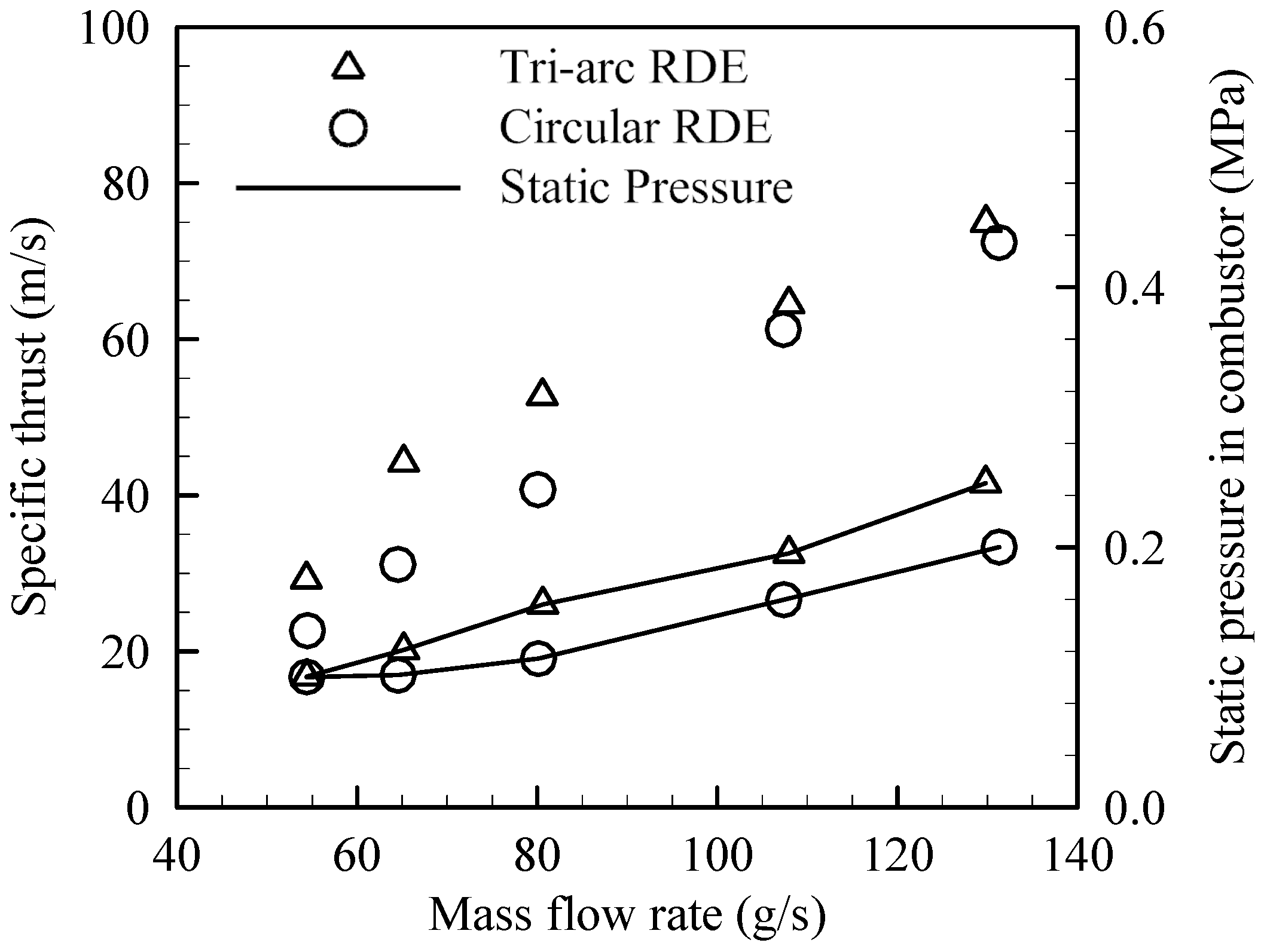
Figure 16 shows the static pressure in the combustion channel and the specific thrust of each RDE. The specific thrust is defined as the ratio of thrust to mass flow rate, where the thrust is the net force generated by the combustion subtracting the force by the propellant injection. The test for each condition was conducted two or more times, and the errors are smaller than the size of the symbol shown in the figure. Thus, the error bar is not plotted. The performance of the tri-arc RDE tends to be greater than that of the circular RDE over the entire mass flow rate range, regardless of velocity deficit. This does not result from the incorrectly measured mass flow rate because the frequencies shown in Table 2 do not have a particular trend, and the difference in performance is too large to be attributed to the combustion channel area or volume. This result is, presumably, caused by the repeated changes in curvature, which enhances the detonation stability
8. Conclusions
As an example of a noncircular cross-section of RDE configuration, a tri-arc RDE was designed, tested, and compared with a circular RDE under the same operating conditions. Operation characteristics of detonation wave propagation were investigated by the high-speed camera images and pressure measurements. STFT and FFT analysis of pressure data showed detonation velocity deficits of 745.24~844.40 m/s with the tri-arc RDE, and 750.88~826.96 m/s with the circular RDE in reference mass flow rate cases (64.8, 80.3, and 107.7 g/s). The velocity deficit tends to decrease as the mass flow rate increases, which we consider to be caused by the simple slot injector design.
Unstable propagation is observed for 54.3 g/s and 130.7 g/s cases, which are considered transitional conditions to different detonation wave numbers. Compared to the circular RDE, the tri-arc RDE has better stability characteristics at the low and high mass flow rate cases, as the longer steady detonation combustion is observed. We consider the repeated changes in curvature to enhance the detonation stability.
Outer wall pressure history at the concave and convex corner exhibit contradictory results to the numerical results that assume a homogeneous mixture. It is reasoned that the present injector design could result in non-homogeneous mixture distribution along the channel, causing strong detonation at the convex corner and weak detonation at the concave corner, though further investigation is necessary. Performance-wise, static pressure in the tri-arc RDE is higher than that of the circular RDE over the entire mass flow rate range, as is the specific thrust. Overall, the tri-arc RDE outperforms the ordinary circular-shaped RDE both in performance and detonation stability, although further investigations would be necessary to understand the underlying physics and optimize the design of the injector and combustor.
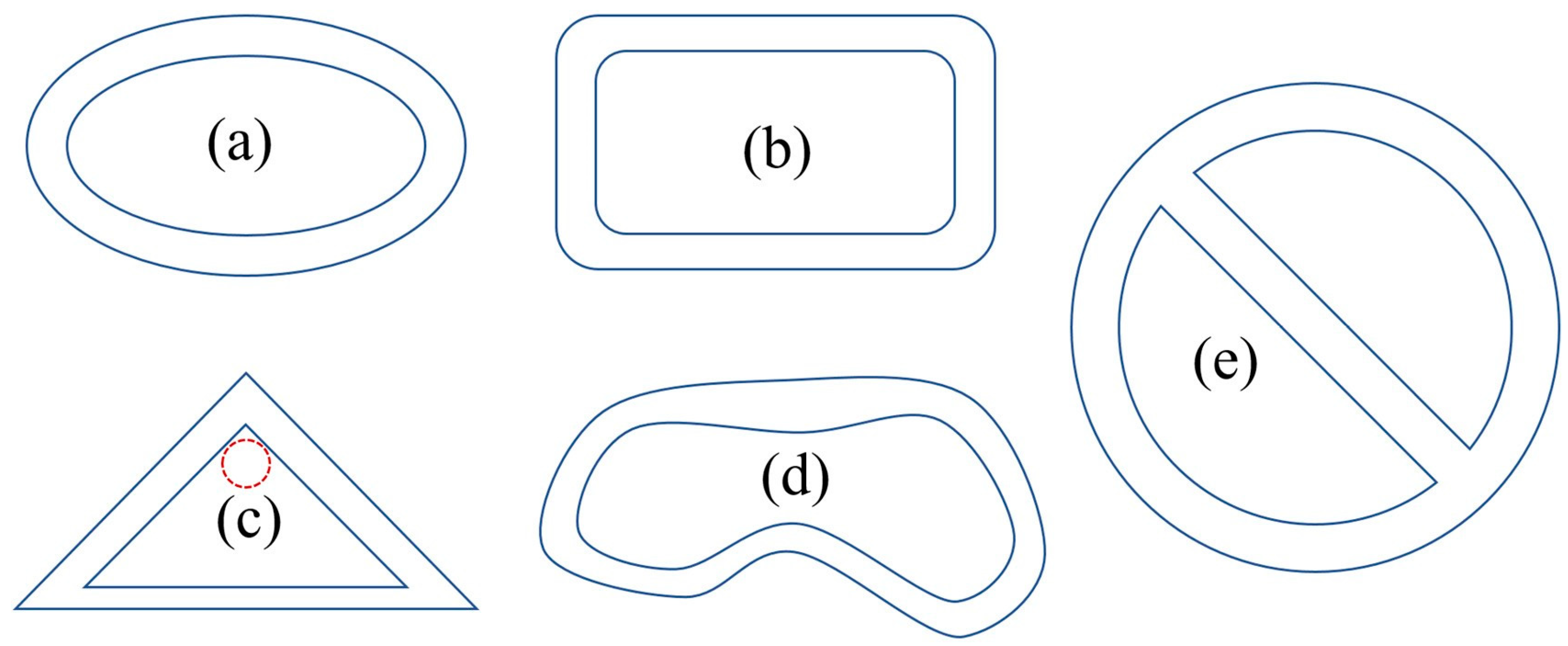
In conclusion, the noncircular RDE of a tri-arc-shaped cross-section was experimentally demonstrated as an example of a noncircular cross-sectioned RDE. Therefore, we consider that a closed channel of any cross-sectional shape can be used for the RDE, which would provide great design flexibility for the integration of the propulsion system into the airframe, especially for the stealth characteristics or aerodynamic performance. Some examples of such cross-sections are plotted in Figure 17, though the possibility of connected channel configuration in Figure 17e should be studied further.
Author Contributions
Conceptualization, J.-Y.C.; methodology, H.-S.H. and J.-Y.C.; software, J.-Y.C.; writing—original draft preparation, J.-H.L., J.-H.R., E.-S.L., H.-S.H. and J.-Y.C.; writing—review and editing, J.-H.L. and J.-Y.C.; visualization, J.-H.L., J.-H.R., E.-S.L. and H.-S.H.; supervision, J.-Y.C.; project administration, J.-Y.C.; funding acquisition, J.-Y.C. All authors have read and agreed to the published version of the manuscript.
Funding
This work was supported by the National Research Foundation (NRF) of Korea grant (NRF-2019R1A2C1004505 and NRF-2022M1A3C2076724) funded by the Ministry of Science and ICT (MSIT) of the Republic of Korea Government.
Data Availability Statement
Not applicable.
Conflicts of Interest
The authors declare no conflict of interest.
References
- Nejaamtheen, M.N.; Kim, T.Y.; Pavalavanni, P.K.; Ryu, J.; Choi, J.-Y. Effects of the dimensionless radius of an annulus on the detonation propagation characteristics in circular and non-circular rotating detonation engines. Shock Waves 2021, 31, 703–715. [Google Scholar] [CrossRef]
- Le Naour, B.; Falempin, F.H.; Coulon, K. MBDA R&T Effort Regarding Continuous Detonation Wave Engine for Propulsion—Status in 2016. In Proceedings of the 21st AIAA International Space Planes and Hypersonics Technologies Conference, Xiamen, China, 6–9 March 2017. [Google Scholar] [CrossRef]
- Gawahara, K.; Nakayama, H.; Kasahara, J.; Matsuoka, K.; Tomioka, S.; Hiraiwa, T.; Matsuo, A.; Funaki, I. Detonation engine development for reaction control systems of a spacecraft. In Proceedings of the 49th AIAA/ASME/SAE/ASEE Joint Propulsion Conference, San Jose, CA, USA, 14–17 July 2013. [Google Scholar]
- Wen, H.; Xie, Q.; Wang, B. Propagation behaviors of rotating detonation in an obround combustor. Combust. Flame 2019, 210, 389–398. [Google Scholar] [CrossRef]
- Peng, H.; Liu, W.; Liu, S. Ethylene Continuous Rotating Detonation in optically accessible racetrack-like combustor. Combust. Sci. Technol. 2018, 191, 676–695. [Google Scholar] [CrossRef]
- Feleo, A.; Chacon, F.; White, L.W.; Gamba, M. Evaluation of OH Emission for Determining Operation of a Rotating Detonation Engine. In Proceedings of the AIAA Scitech 2019 Forum, San Diego, CA, USA, 7–11 January 2019. [Google Scholar] [CrossRef]
- Chacon, F.; Gamba, M. Study of Parasitic Combustion in an Optically Accessible Continuous Wave Rotating Detonation Engine. In Proceedings of the 2019 AIAA Scitech Forum, San Diego, CA, USA, 7–11 January 2019. [Google Scholar]
- Chacon, F.; Gamba, M. OH PLIF Visualization of an Optically Accessible Rotating Detonation Combustor. In Proceedings of the 2019 AIAA Propulsion and Energy Forum, Indianapolis, IN, USA, 19–22 August 2019. [Google Scholar]
- Chacon, F.; Gamba, M. Development of an optically accessible continuous wave Rotating Detonation Engine. In Proceedings of the 2018 Joint Propulsion Conference, Cincinnati, OH, USA, 9–11 July 2018. [Google Scholar] [CrossRef]
- Sosa, J.; Ahmed, K.A.; Fievisohn, R.; Hoke, J.; Ombrello, T.; Schauer, F. Supersonic driven detonation dynamics for rotating detonation engines. Int. J. Hydrogen Energy 2019, 44, 7596–7606. [Google Scholar] [CrossRef]
- Lee, S.-H.; Cho, D.-R.; Choi, J.-Y. Numerical Analysis of Detonation Wave Propagation Characteristics in Annular Channels. J. KSPE 2008, 12, 26–37. [Google Scholar]
- Kudo, Y.; Nagura, Y.; Kasahara, J.; Sasamoto, Y.; Matsuo, A. Oblique detonation waves stabilized in rectangular-cross-section bent tubes. Proc. Combust. Inst. 2011, 33, 2319–2326. [Google Scholar] [CrossRef] [Green Version]
- Nakayama, H.; Moriya, T.; Kasahara, J.; Matsuo, A.; Sasamoto, Y.; Funaki, I. Stable detonation wave propagation in rectangular-cross-section curved channels. Combust. Flame 2012, 159, 859–869. [Google Scholar] [CrossRef] [Green Version]
- Nakayama, H.; Kasahara, J.; Matsuo, A.; Funaki, I. Front shock behavior of stable curved detonation waves in rectangular-cross-section curved channels. Proc. Combust. Inst. 2013, 34, 1939–1947. [Google Scholar] [CrossRef]
- Sugiyama, Y.; Nakayama, Y.; Matsuo, A.; Nakayama, H.; Kasahara, J. Numerical Investigations on Detonation Propagation in a Two-Dimensional Cured Channel. Combust. Sci. Tech. 2014, 186, 1662–1679. [Google Scholar] [CrossRef]
- Pan, Z.; Qi, J.; Pan, J.; Zhang, P.; Zhu, Y.; Gui, M. Fabrication of a helical detonation channel: Effect of initial pressure on the detonation propagation modes of ethylene/oxygen mixtures. Combust. Flame 2018, 192, 1–9. [Google Scholar] [CrossRef]
- Pan, Z.; Chen, K.; Qi, J.; Zhang, P.; Zhu, Y.; Pan, J.; Gui, M. The propagation characteristics of curved detonation wave: Experiments in helical channels. Proc. Combust. Inst. 2019, 37, 3585–3592. [Google Scholar] [CrossRef]
- Xia, Z.; Ma, H.; Zhuo, C.; Zhou, C. Propagation process of H2/air rotating detonation wave and influence factors in plane-radial structure. Int. J. Hydrogen Energy 2018, 43, 4609–4622. [Google Scholar] [CrossRef]
- Kawasaki, A.; Inakawa, T.; Kasahara, J.; Goto, K.; Matsuoka, K.; Matsuo, A.; Funaki, I. Critical condition of inner cylinder radius for sustaining rotating detonation waves in rotating detonation engine thruster. Proc. Combust. Inst. 2018, 37, 3461–3469. [Google Scholar] [CrossRef]
- Katta, V.R.; Cho, K.Y.; Hoke, J.L.; Codoni, J.R.; Schauer, F.R.; Roquemore, W.M. Effect of increasing channel width on the structure of rotating detonation wave. Proc. Combust. Inst. 2019, 37, 3575–3583. [Google Scholar] [CrossRef]
- Zhou, R.; Wang, J.-P. Numerical investigation of shock wave reflections near the head ends of rotating detonation engines. Shock. Waves 2013, 23, 461–472. [Google Scholar] [CrossRef]
- Zhao, N.; Meng, Q.; Zheng, H.; Li, Z.; Deng, F. Numerical study of the influence of annular width on the rotating detonation wave in a non-premixed combustor. Aerosp. Sci. Technol. 2020, 100, 105825. [Google Scholar] [CrossRef]
- Wang, Y. Rotating detonation in a combustor of trapezoidal cross section for the hydrogen–air mixture. Int. J. Hydrogen Energy 2016, 41, 5605–5616. [Google Scholar] [CrossRef]
- Han, H.-S.; Lee, E.; Choi, J.-Y. An Experimental Investigation of C2H4/GO2 Rocket-type Rotating Detonation Engine with Circular Chamber. Energies 2021, 14, 1381. [Google Scholar] [CrossRef]
- Hansmetzger, S.; Zitoun, R.; Vidal, P. Detonation Regimes in a Small-scale RDE. In Proceedings of the 26th International Colloquium on the Dynamics of Explosions and Reactive Systems, Boston, MA, USA, 30 July–4 August 2017. [Google Scholar]
- Wolanski, P. Rotating Detonation Wave Stability. In Proceedings of the 23rd International Colloquium on the Dynamics of Explosions and Reactive Systems, Irvine, CA, USA, 23–29 July 2011. [Google Scholar]
- Choi, J.Y.; Ma, F.H.; Yang, V. Some numerical issues on simulation of detonation cell structures. Combust. Explos. Shock. Waves 2008, 44, 560–578. [Google Scholar] [CrossRef]
- Choi, J.; Jeung, I.-S.; Yoon, Y. Computational fluid dynamics algorithms for unsteady shock-induced combustion, Part 1: Validation. AIAA J. 2000, 38, 1179–1187. [Google Scholar] [CrossRef]
- Choi, J.; Jeung, I.-S.; Yoon, Y. Computational fluid dynamics algorithms for unsteady shock-induced combustion, Part 2: Comparison. AIAA J. 2000, 38, 1188–1195. [Google Scholar] [CrossRef]
- Choi, J.; Unnikrishnan, U.; Hwang, W.; Jeong, S.; Han, S.; Kim, K.; Yang, V. Effect of fuel temperature on flame characteristics of supersonic turbulent combustion. Fuel 2022, 329, 125310. [Google Scholar] [CrossRef]
Figure 1.
Numerical smoked-foil records of detonation wave propagation through various cross-sectional shapes, adapted from [1].
Figure 1.
Numerical smoked-foil records of detonation wave propagation through various cross-sectional shapes, adapted from [1].

Figure 2.
Channel cross-section of circular and tri-arc RDEs.

Figure 3.
(a) Longitudinal cross-section of the tri-arc/circular RDEs, (b) details of fuel and oxidizer injectors.
Figure 3.
(a) Longitudinal cross-section of the tri-arc/circular RDEs, (b) details of fuel and oxidizer injectors.

Figure 4.
A picture of the experimental setup.

Figure 5.
The mass flow rates of fuel and oxidizer in the tri-arc and circular RDEs.

Figure 6.
Pressure history of plenums, combustion channel, and pre-detonator at g/s for ((a) overall operation, (b) combustion phase).
Figure 6.
Pressure history of plenums, combustion channel, and pre-detonator at g/s for ((a) overall operation, (b) combustion phase).

Figure 7.
RDE hot fire test sequence programmed in the PLC.

Figure 8.
Experimental visualization (upper), STFT (lower-left) and FFT (lower-right) results at reference mass flow rate, g/s for ; tri-arc (a) and circular (b) RDEs.
Figure 8.
Experimental visualization (upper), STFT (lower-left) and FFT (lower-right) results at reference mass flow rate, g/s for ; tri-arc (a) and circular (b) RDEs.

Figure 9.
Experimental visualization (upper), STFT (lower-left), and FFT (lower-right) results at low mass flow rate, g/s for ; tri-arc (a) and circular (b) RDEs.
Figure 9.
Experimental visualization (upper), STFT (lower-left), and FFT (lower-right) results at low mass flow rate, g/s for ; tri-arc (a) and circular (b) RDEs.

Figure 10.
Experimental visualization (upper), STFT (lower-left), and FFT (lower-right) results at high mass flow rate, g/s for ; tri-arc (a) and circular (b) RDEs.
Figure 10.
Experimental visualization (upper), STFT (lower-left), and FFT (lower-right) results at high mass flow rate, g/s for ; tri-arc (a) and circular (b) RDEs.

Figure 11.
Local maximum pressure traces showing detonation cell structures from numerical analysis of the tri-arc RDE.
Figure 11.
Local maximum pressure traces showing detonation cell structures from numerical analysis of the tri-arc RDE.

Figure 12.
Pressure variation along the outer wall from the numerical analysis of tri-arc RDE.

Figure 13.
Pressure history at the concave corner (p1) for the mass flow rate g/s.

Figure 14.
Dominant amplitudes of detonation pressure at the concave (p1) and convex (p2) corners of the outer wall of the combustion channel acquired from the FFT.
Figure 14.
Dominant amplitudes of detonation pressure at the concave (p1) and convex (p2) corners of the outer wall of the combustion channel acquired from the FFT.

Figure 15.
Schematics fuel injection characteristics of tri-arc RDE.

Figure 16.
Specific thrust and static pressure of the tri-arc and circular RDEs.

Figure 17.
Various noncircular RDE cross-section configurations: (a) oval-shaped, (b) rounded- rectangular, (c) triangular, (d) arbitrary-shaped with changing width, and (e) connected channels [1].
Figure 17.
Various noncircular RDE cross-section configurations: (a) oval-shaped, (b) rounded- rectangular, (c) triangular, (d) arbitrary-shaped with changing width, and (e) connected channels [1].


Table 1.
Geometric dimensions for the tri-arc and circular RDEs.
| Combustor Length (mm) | Slot Width (mm) | Cross-Sectional Area (mm2) | r/H | ||||
|---|---|---|---|---|---|---|---|
| Fuel Slot | Oxidizer Slot | Fuel Slot | Oxidizer Slot | Combustor | |||
| Tri-arc RDE | 75.00 | 0.34 | 0.40 | 46.80 | 63.30 | 771.4 | 3.55–6.50 |
| Circular RDE | 75.00 | 0.30 | 0.46 | 47.10 | 72.80 | 758.7 | 6.06 |
| Hansmetzger [25] | 90 | 0.3 | 0.5 | 47.12 | 79.33 | 1885.00 | 3.5 |
Table 2.
Operation characteristics of tri-arc and circular RDEs for the other mass flow rate conditions.
Table 2.
Operation characteristics of tri-arc and circular RDEs for the other mass flow rate conditions.
| (g/s) | Φ | RDE Type | Stability | Dominant Frequency (kHz) | Velocity Deficit (m/s) |
|---|---|---|---|---|---|
| 64.8 0.32 | 1.03 0.001 | Tri-arc | Stable | 16.71 | 844.40 |
| Circular | Stable, temporarily unstable | 16.88 | 826.96 | ||
| 80.3 0.20 | 1.04 0.001 | Tri-arc | Stable | 16.72 | 843.47 |
| Circular | Stable | 17.60 | 760.16 | ||
| 107.7 0.71 | 1.04 0.008 | Tri-arc | Stable | 17.78 | 745.24 |
| Circular | Stable | 17.70 | 750.88 |
Table 3.
The initial condition of numerical analysis of the tri-arc RDE.
| Description | Value | |
|---|---|---|
| Specific heat ratio | Unburned gas | 1.602 |
| Burned gas | 1.288 | |
| Dimensionless heat addition | 24.2 | |
| Dimensionless activation energy | 32.46 | |
Disclaimer/Publisher’s Note: The statements, opinions and data contained in all publications are solely those of the individual author(s) and contributor(s) and not of MDPI and/or the editor(s). MDPI and/or the editor(s) disclaim responsibility for any injury to people or property resulting from any ideas, methods, instructions or products referred to in the content. |
© 2022 by the authors. Licensee MDPI, Basel, Switzerland. This article is an open access article distributed under the terms and conditions of the Creative Commons Attribution (CC BY) license (https://creativecommons.org/licenses/by/4.0/).
Share and Cite
MDPI and ACS Style
Lee, J.-H.; Ryu, J.-H.; Lee, E.-S.; Han, H.-S.; Choi, J.-Y. Experimental Proof of Concept of a Noncircular Rotating Detonation Engine (RDE) for Propulsion Applications. Aerospace 2023, 10, 27. https://doi.org/10.3390/aerospace10010027
AMA Style
Lee J-H, Ryu J-H, Lee E-S, Han H-S, Choi J-Y. Experimental Proof of Concept of a Noncircular Rotating Detonation Engine (RDE) for Propulsion Applications. Aerospace. 2023; 10(1):27. https://doi.org/10.3390/aerospace10010027
Chicago/Turabian StyleLee, Jae-Hyuk, Jae-Hoon Ryu, Eun-Sung Lee, Hyung-Seok Han, and Jeong-Yeol Choi. 2023. "Experimental Proof of Concept of a Noncircular Rotating Detonation Engine (RDE) for Propulsion Applications" Aerospace 10, no. 1: 27. https://doi.org/10.3390/aerospace10010027
Note that from the first issue of 2016, this journal uses article numbers instead of page numbers. See further details here.