Article

Antenna Delay-Independent Simultaneous Ranging for UWB-Based RTLSs

by
Shashi Shah
1,
Sushank Chaudhary
1,
Rizwan Ullah
1,
Amir Parnianifard
1,
Muhammad Zain Siddiqi
1,
Pisit Vanichchanunt
2,
Wiroonsak Santipach
3 and
Lunchakorn Wuttisittikulkij
1,*
1
Wireless Communication Ecosystem Research Unit, Department of Electrical Engineering, Chulalongkorn University, Bangkok 10330, Thailand
2
Faculty of Engineering, King Mongkut’s University of Technology North Bangkok, Bangkok 10800, Thailand
3
Department of Electrical Engineering, Kasetsart University, Bangkok 10900, Thailand
*
Author to whom correspondence should be addressed.
J. Sens. Actuator Netw. 2023, 12(1), 1; https://doi.org/10.3390/jsan12010001
Submission received: 29 November 2022 / Revised: 16 December 2022 / Accepted: 16 December 2022 / Published: 22 December 2022

Abstract

:
The ultra-wideband (UWB)-based real-time localization system (RTLS) is a promising technology for locating and tracking assets and personnel in real-time within a defined indoor environment since it provides high-ranging accuracy. However, its performance can be affected by the underlying antenna delays of UWB nodes, which act as a source of error during range estimations. Usually, measurement of the antenna delays is performed separately as a dedicated standalone procedure. Such an additional measurement procedure makes the UWB-based RTLS more tedious with manual interventions. Moreover, the air-time occupancy during the transmission and reception of signaling messages for range estimations between UWB node pairs also limits the serviceable capability of these networks. In this regard, we present a novel simultaneous ranging scheme that requires limited air-time occupancy during range estimations between UWB node pairs and also compensates for the error from the antenna delays. This paper provides a detailed mathematical modeling, system design, and implementation procedure of the proposed scheme. The effectiveness of the proposed scheme for locating a mobile node in an indoor environment is validated through experimental analysis. The results show that, compared to the state-of-the-art two-way ranging (TWR) method, the proposed scheme eliminates the requirement of dedicated standalone antenna delay measurement procedures of the nodes, increases air efficiency through the provision of simultaneous ranging, and provides relative root-mean-square errors (RMSEs) improvement for range and position estimations of approximately 54.52 % and 39.96 % , respectively.

1. Introduction

Location-based services play a vital role in modern society [1,2], and the applications of RTLSs have been gaining significant attention in recent years as a result of advancement in ubiquitous wireless connectivity with an escalation of communication devices [3,4,5,6]. The global positioning system (GPS) [7,8] is commonly used for localization and tracking applications as they provide global coverage. However, it is preferable for outdoor environments because of line-of-sight (LOS) requirements with the GPS satellites [9,10], and the localization accuracy is compromised to 1–5 m when using consumer-grade devices [7]. In this regard, the UWB-based RTLSs is gaining much attention for indoor localization and tracking applications since they provide high localization accuracy, better material penetrability, and scalable network coverage with low power consumption [11]. It was introduced in IEEE 802.15.4a [12,13] and included in the IEEE 802.15.4 UWB physical layer [14]. IEEE 802.15.4z-2020 standard was released recently in 2020 [15], which introduced new features to enhance the UWB standards, such as improved ranging, reduction in air-time occupancy, introduction to simultaneous ranging, and timestamp robustness.
UWB-based RTLSs consist of a reference positioning system of fixed position infrastructure nodes, called anchor nodes, for localization and tracking of mobile nodes within the coverage area [16,17]. A commonly used metric is time-of-flight (TOF), also known as time-of-arrival, which relies on UWB signals of high time resolution with nanosecond accuracy [18], and hence, relatively increases the accuracy compared to other techniques [19]. The TOF estimations between UWB nodes are done by TWR methods [14,20,21,22], which typically rely on the transmission and reception timestamps information of UWB signals. The TWR techniques described in literature [14,20,21,22] primarily aim to reduce the TOF errors from UWB nodes’ clock offsets that arise from physical clock oscillator imperfections [23]. The single-sided TWR (SS-TWR) was introduced in IEEE 802.15.4 [14] as an alternative to one-way ranging. Only two UWB signals are used by the SS-TWR throughout the ranging process, and the TOF is calculated from the signals’ round-trip times. It is significantly hampered, however, by the UWB nodes’ clock offset, which is proportional to the reply-time between the two UWB signals [24]. By applying reply-delay time constraints, the symmetric double-sided TWR (SDS-TWR) [20] and the asymmetric double-sided TWR (ADS-TWR) [21] significantly reduce the TOF estimation error caused by the clock offsets. While the ADS-TWR considers the final reply-delay time to be zero, the SDS-TWR demands that the two reply-delay time durations be equal. Such restrictions may not be feasible since the signals from different nodes may carry variable length data in a typical system [24]. Based on the performance comparison of the state-of-the-art TWR methods in [24,25], the alternative double-sided TWR (AltDS-TWR) [22] is the most preferred in real-world scenarios as it provides robustness against variation of reply-delay time and clock offsets. While the aforementioned techniques try to reduce TOF error caused by the clock offset, the necessity of several signaling messages between UWB node pairs during TWR tends to increase air-time occupancy and reduce the number of serviceable mobile nodes in RTLSs [26].
Additionally, the antenna delay of UWB nodes has a significant impact on the accuracy of UWB-based RTLSs [27,28]. It occurs due to the underlying analog circuitry of the UWB nodes and introduces a quasistatic bias to the timestamps [28]. Hence, the reported timestamps by the UWB nodes are coupled with biases due to antenna delays. When compared to the actual timestamp values, the reported timestamps are typically different. Although these biases seem small and vary slightly from device to device, they still lead to significant errors in the estimated ranges and affect the accuracy by tens of centimeters in the UWB-based RTLSs since the signals under measurement are moving at the speed of light. Such performance inefficiency is unsuitable for indoor RTLS applications that usually require stringent localization accuracy [29]. Usually, the measurement of the antenna delay values is done as a dedicated standalone procedure. Several methods are available in the literature to determine the antenna delays of UWB nodes [28,30,31,32,33,34]. They typically differ in the TWR techniques used [14,20,21,22], as well as the number of ranging sessions carried out between each UWB node pair. However, the requirement of dedicated standalone antenna delay measurement procedures, which are often time-consuming and frequently include manual interventions, hinders the desirable plug-and-play functionality of UWB-based RTLS.
In this work, we propose a novel ranging scheme for simultaneous range measurements between a mobile node and anchor nodes without requiring any knowledge of the UWB nodes’ antenna delay values. We consider UWB-based RTLSs where the antenna delay values are usually node-dependent that need to be pre-measured to achieve accurate ranging. Then, we demonstrate through mathematical modeling that the proposed scheme is independent of such node-dependent constants. Hence, it simplifies the UWB-based RTLSs with no requirement for dedicated standalone antenna delay measurement procedures of the nodes. Further, the provision of simultaneous ranging makes the proposed scheme more air efficient and capable of performing multiple range estimations with a limited number of transmissions and receptions of signaling messages. We then provide a detailed discussion of the system design and its implementation procedures. Finally, we evaluate the proposed scheme for its effectiveness by an experiment considering RTLS application in an indoor environment and compare the results with other state-of-the-art TWR methods for different performance metrics. The following summarizes the primary characteristics of the proposed scheme.
  • A TWR session simultaneously measures the ranges between a mobile node and several anchor nodes,
  • knowledge or measurement of UWB nodes’ antenna delay values are not required for the range estimations,
  • relatively faster-ranging sessions with limited air-time occupancy, and
  • clock synchronization is not required between any of the involved UWB nodes.

2. Antenna Delay-Independent Simultaneous Ranging

This section provides a detailed mathematical modeling, system design, and implementation procedure of the proposed scheme. We design the system based on a characteristic of the reception time difference of two signaling messages sent by two UWB nodes. It provides simultaneous ranging in UWB-based RTLSs without having any knowledge or measurement requirement of UWB nodes’ antenna delay values.

2.1. Mathematical Modeling

Consider a wireless UWB network that comprises of anchor and mobile nodes, where each node can employ UWB signals to precisely extract timestamp information between the nodes with nanosecond accuracy. The anchor nodes are divided into two types: active anchor nodes that actively transmit packets during a TWR session and passive anchor nodes that only listen to packets during a TWR session. Suppose that the first and second packets during a TWR session, hereinafter referred to as sensing packets, are transmitted by a mobile node, M , and an active anchor node, A , respectively as shown in Figure 1. Let us consider the reception time difference of these two sensing packets at node i to be denoted as P i . Then, for any two UWB nodes in the network, i and j, we have [25]
P i P j = ( T A i T A j ) ( T M i T M j ) ,
where T i j denotes the TOF between node i’s antenna and node j’s antenna.
Suppose that the reception time difference was to be computed by a preferred clock, and without loss of generality, let the selected preferred clock be that of node M . To make this calculation possible, allow node M to transmit the third sensing packet of the TWR session as shown in Figure 1. Then, the clock speed ratio of node M and node i is given by [25]
r i M = 1 , if i = M t M Tx ( 3 ) t M Tx ( 1 ) t i Rx ( 3 ) t i Rx ( 1 ) , otherwise ,
where t i Tx ( k ) and t i Rx ( k ) respectively denotes the transmission and reception timestamp values of the k-th packet reported by node i. Observing the terms of (2) in Figure 1, we can see that r i M gives the ratio of node M clock speed over node i clock speed. It reflects the clock offset of node i with respect to the preferred clock of node M . A value greater than one means that the clock of node i is running slower than that of node M , smaller than one means that the clock of node i is running faster than that of node M , and equal to one means that the clock of node i is running same as of node M . Now, the derivation of the reception time difference for each node as if it was measured by the preferred clock of node M will be discussed herein. Consider d i Tx ( k ) and d i Rx ( k ) respectively denoting the transmission and reception timestamp biases due to antenna delay of node i for the k-th packet to comply with the following statement. The preferred clock-based timestamp, i.e., as referenced to the clock of node M , at which the k-th packet arrives at node i’s antenna equals τ i Tx ( k ) + d i Tx ( k ) during transmission, and equals τ i Rx ( k ) d i Rx ( k ) during reception, where τ i Tx ( k ) and τ i Rx ( k ) respectively denote the preferred clock-based timestamps coincident with t i Tx ( k ) and t i Rx ( k ) . Then, the reception time difference of nodes M , A , and any passive anchor node x n from X = { x 1 , x 2 , , x N } , n { 1 , , N } in the UWB network can be computed by [25]
P M = ( τ M Rx ( 2 ) d M Rx ( 2 ) ) ( τ M Tx ( 1 ) + d M Tx ( 1 ) ) = ( τ M Rx ( 2 ) τ M Tx ( 1 ) ) ( d M Tx ( 1 ) + d M Rx ( 2 ) ) = ( t M Rx ( 2 ) t M Tx ( 1 ) ) ( d M Tx ( 1 ) + d M Rx ( 2 ) ) ,
P A = ( τ A Tx ( 2 ) + d A Tx ( 2 ) ) ( τ A Rx ( 1 ) d A Rx ( 1 ) ) = ( τ A Tx ( 2 ) τ A Rx ( 1 ) ) + ( d A Rx ( 1 ) + d A Tx ( 2 ) ) = ( t A Tx ( 2 ) t A Rx ( 1 ) ) r A M + ( d A Rx ( 1 ) + d A Tx ( 2 ) ) ,
and
P x n = ( τ x n Rx ( 2 ) d x n Rx ( 2 ) ) ( τ x n Rx ( 1 ) d x n Rx ( 1 ) ) = ( τ x n Rx ( 2 ) τ x n Rx ( 1 ) ) + ( d x n Rx ( 1 ) d x n Rx ( 2 ) ) = ( t x n Rx ( 2 ) t x n Rx ( 1 ) ) r x n M + ( d x n Rx ( 1 ) d x n Rx ( 2 ) ) , n { 1 , , N } .
Note that the transmission and reception timestamp biases due to antenna delay in (3)–(5) are specifically dependent on the node, and are caused mainly by their underlying analog circuitry [28]. Then, as in [32], d i Tx ( k ) and d i Rx ( k ) can be treated as node i’s specific constants and independent of packets. Therefore, the aggregate timestamp biases due to antenna delay conditioned on the first two sensing packets for nodes M and A , i.e., d M Tx ( 1 ) + d M Rx ( 2 ) in (3) and d A Rx ( 1 ) + d A Tx ( 2 ) in (4), can be treated as a node specific constant called aggregate antenna delays, denoted as d M and d A respectively. Similarly, the aggregate timestamp bias due to antenna delay conditioned on the first and second packets for node x n , i.e., d x n Rx ( 1 ) d x n Rx ( 2 ) in (5), can be considered zero. Hence, (3)–(5) can be rewritten as
P M = ( t M Rx ( 2 ) t M Tx ( 1 ) ) d M ,
P A = ( t A Tx ( 2 ) t A Rx ( 1 ) ) r A M + d A ,
and
P x n = ( t x n Rx ( 2 ) t x n Rx ( 1 ) ) r x n M , n { 1 , , N } .
The reception time difference can then be calculated locally by each node using (6)–(8), and the results may be gathered into a computing unit for further processing. Moreover, from (8), we note that the reception time difference is independent of the timestamp bias due to antenna delay in the passive anchor nodes. Since there are N number of passive anchor nodes in the UWB network, then for any distinct pair of passive anchor nodes, ( x i , x j ) { x 1 , x 2 , , x N } and i j , we can construct N ( N 1 ) 2 number of independent equations based on (1) such that
P x i P x j = ( T A x i T A x j ) ( T M x i T M x j ) .
Rearranging the terms in (9), we obtain
T M x i T M x j = ( T A x i T A x j ) ( P x i P x j ) .
Now, when we multiply both sides of (10) with the speed of light, we obtain
R ( M , x i ) R ( M , x j ) = R ( A , x i ) R ( A , x j ) β ( x i , x j ) ,
where R ( i , j ) is the range between node pair i and j, and β ( i , j ) is calculated from the reception time difference of nodes i and j. In (11), the values of all three components on the right-hand side are obtained from computation and can be considered as a known constant. Hence, we obtain a system that consists of N ( N 1 ) 2 independent equations and N unknown variables, where the least-squares method can be used to simultaneously estimate the ranges between the mobile node and passive anchor nodes, i.e., R ( M , x n ) , n { 1 , , N } .

2.2. System Design and Implementation

We design the system to simultaneously estimate the ranges between node pairs, a mobile node and passive anchor nodes, in a UWB network after a single measurement process. The system is configured to operate as follows. The system setup consists of an active anchor node, A , a set of N passive anchor nodes, X = { x 1 , x 2 , , x N } , and a mobile node, M . All transmissions to and from these nodes are transmitted and received over the air. The mobile node is positioned at a fixed unknown point, while the anchor nodes are situated at fixed N + 1 known positions. Actual distances between anchor node pairs, active and passive, have been measured and are known. A complementary UWB node, known as the master node, is also a part of the system. It is used to initiate TWR sessions, gather session-data (the reception time difference values) from all passive anchor nodes, and send the session-data to a PC using a serial UART. The mobile node is the preferred clock’s chosen node during a TWR session, and it sends the first and third sensing packets. The active anchor node transmits the second sensing packet, and the passive nodes listen to all three sensing packets. The gathered sets of session-data are analyzed at the PC once a predetermined number of TWR sessions have been completed, and the least-squares method is used to simultaneously estimate the ranges between the mobile node and passive anchor nodes.
The following is the order in which the simultaneous ranging measurement operation proceeds.
Step 1:
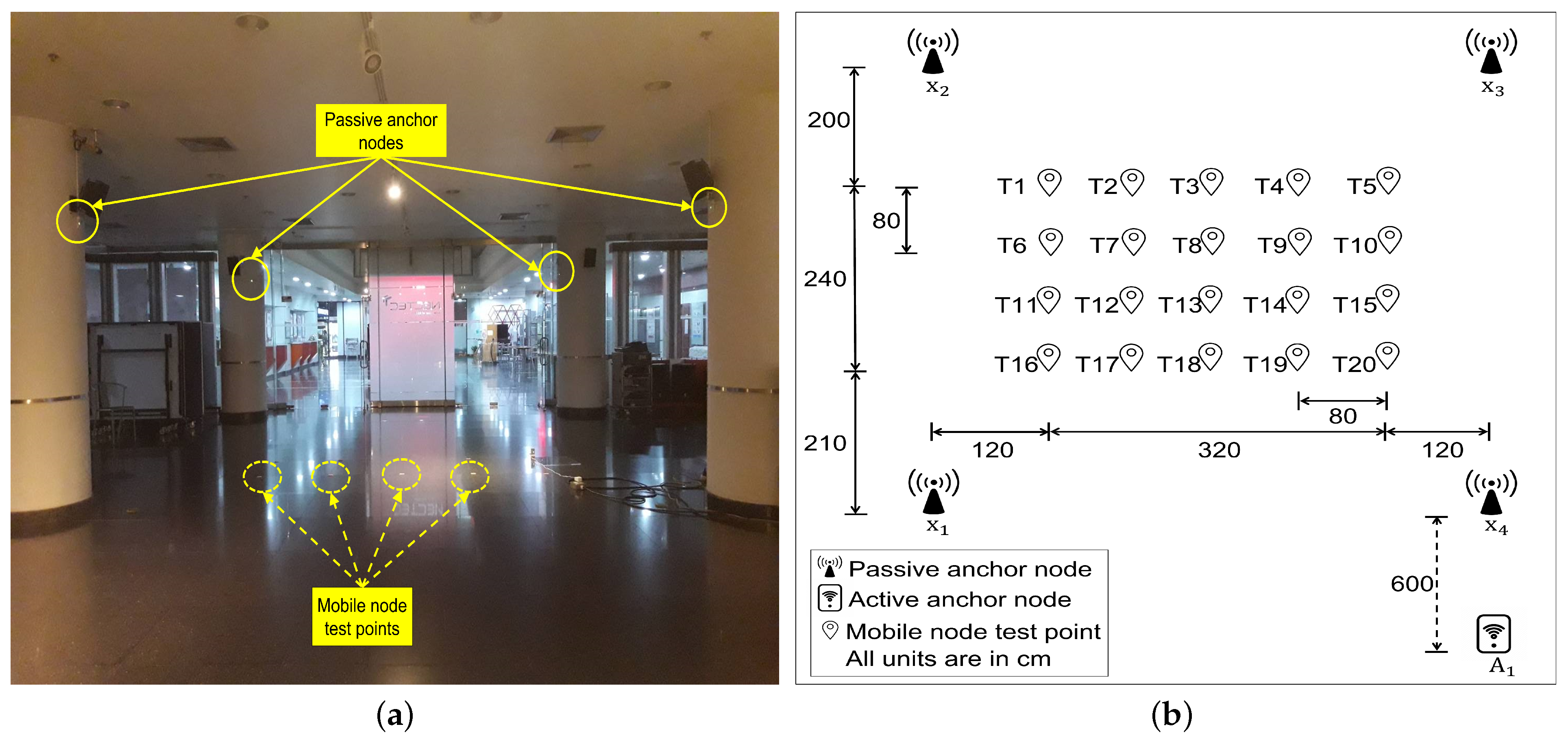
Place each powered anchor node in its corresponding fixed, well-known position.
Step 2:
Identify an active anchor node, A , and passive anchor nodes, X = { x 1 , x 2 , , x N } , and measure the distances between them.
Step 3:
Place the powered mobile node, M , in an arbitrary location.
Step 4:
Session-data collection.
Step 4.1:
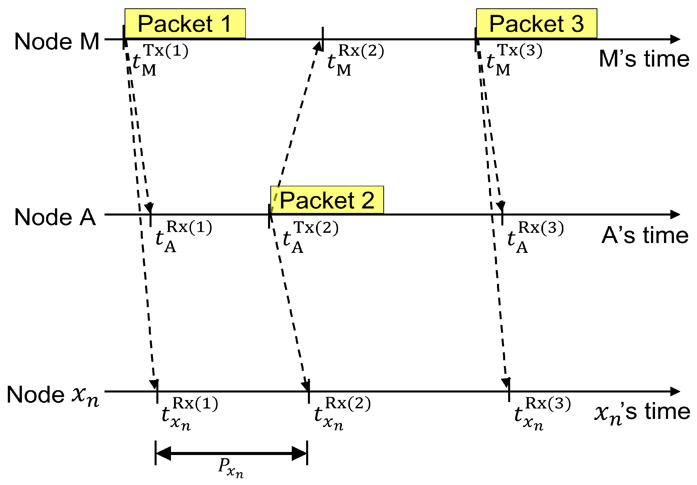
Upon the PC’s request, the master node issues the command to begin a TWR session. It then assigns M to transmit the first and third sensing packets, A to transmit the second sensing packet, and X to listen to the packets.
Step 4.2:
Upon completion of a TWR session, X computes their corresponding reception time difference based on (8).
Step 4.3:
After a successful TWR session, the master node gathers and stores the session-data of respective nodes as a log file into the PC.
Step 4.4:
The Step 4.1 through Step 4.3 processes is continued for 1000 sets of log files.
Step 5:
The processing of the collected log files is performed at the PC, where the ranges between M and X are simultaneously estimated by the least-squares method.
According to the above-discussed cooperation, the system’s entities are implemented. The UWB nodes in our system are DW1000 UWB transceivers from Decawave [35], which adhere to IEEE 802.15.4-2011 specification [14]. Segger Embedded Studio [36] was used as an integrated development environment for C programming to implement the operations on these UWB nodes. Python programming was used to carry out the task on the PC.

3. Numerical Results

3.1. Air-Time Occupancy

The number of packets transmitted during a ranging session in a UWB network of fixed infrastructure nodes is used in this evaluation to measure the air-time occupancy of the proposed scheme. The higher number of required packets increases the air-time occupancy and leads to an increment in the total time duration for the completion of each ranging session. Suppose the network consists of an active anchor node and N number of passive anchor nodes that serve the same coverage area. Then, as detailed in Section 2.2, the proposed system requires only three sensing packets between a mobile node and an active anchor node to simultaneously estimate ranges between the mobile node and all the passive anchor nodes. For comparative analysis with other state-of-the-art TWR schemes, we analyze the required number of sensing packets needed to achieve ranging between a mobile node and N number of passive anchor nodes. The three ranging schemes, SS-TWR [14], SDS-TWR [14], and AltDS-TWR [22], require dedicated ranging sessions performed between the mobile and each of the anchor nodes to estimate their corresponding ranges. In this regard, SS-TWR requires two sensing packets per N number of ranging sessions. While SDS-TWR and AltDS-TWR require three sensing packets per N number of ranging sessions. Note that the alternative double-sided TWR with passive ranging (AltDS-TWR&PR) [37] was proposed as an enhancement over AlTDS-TWR taking into account reducing the number of packets over the air. Here, the ranging between a mobile node and passive anchor nodes can be achieved simultaneously as in the proposed scheme. The implementation of a ranging session in AltDS-TWR&PR, however, is not flexible enough to support a range of RTLS applications because it must be initiated by an active anchor node, and thus requires a total of four sensing packets.
For a general UWB network scenario, Table 1 compares the air-time occupancy of the proposed scheme to SS-TWR, SDS-TWR, AltDS-TWR, and AltDS-TWR&PR. According to the proposed scheme and AltDS-TWR&PR, the number of sensing packets needed for ranging between a mobile node and passive anchor nodes is not dependent on the number of anchor nodes in the network. Additionally, as shown in Table 1, the proposed scheme is relatively the most air efficient and requires the least number of sensing packets in a ranging session.

3.2. Experimental Evaluation

In this section, we discuss the experimental evaluation findings of the proposed scheme taking into account an indoor UWB-based RTLS application. The experiments were performed in an open hallway with provision of LOS between all the UWB nodes as shown in Figure 2a. Although several non-LOS (NLOS) mitigation techniques are available in literature [38,39,40], the estimated TOFs from NLOS conditions are not able to provide LOS-equivalent results. Therefore, to ensure that TOFs from NLOS conditions are rarely utilized, such a positioning of the UWB nodes was taken into consideration for the experimental evaluation of the proposed scheme’s ranging accuracy. In order to carry out the experiment, the setup included a PC and seven UWB nodes: a master node, a mobile node, and five anchor nodes, where one anchor node was identified as an active anchor node and the remaining four were chosen as passive anchor nodes. Here, the master node was used to command the beginning of a TWR session, gather session-data from all relevant nodes, and log them to the PC using a serial UART. All of the UWB nodes were based on Decawave’s DW1000 UWB transceivers [35], which adhere to the IEEE 802.15.4-2011 specification [14].
Now, we localize a mobile node utilizing the proposed scheme with the anchor nodes at a number of test points in LOS coverage and assess its accuracy. In this regard, let the address identification of the active anchor node be A 1 , and the four passive anchor nodes be x 1 , x 2 , x 3 , and x 4 as shown in Figure 2b. These nodes were mounted above ground-level on separate pillars in an open hallway with pre-measured position coordinates (unit: cm): A 1 = ( 120 , 1130 , 200 ) , x 1 = ( 440 , 530 , 200 ) , x 2 = ( 440 , 120 , 200 ) , x 3 = ( 120 , 120 , 200 ) , and x 4 = ( 120 , 530 , 200 ) . The mobile node was to be localized at a set of 20 ground-level test points, labeled as T1, T2, …, T20 as shown in Figure 2b. At each test point, a mobile node was placed, and 1000 sets of log files containing session-data of ranging sessions were collected. The data in those log files were processed using least-squares method to simultaneously estimate the ranges between the mobile node and the four passive anchor nodes. Finally, the RMSEs of the estimated ranges were calculated to analyze the accuracy of the proposed scheme by comparing them with the results from two cases of the AltDS-TWR scheme: AltDS-TWR (w/Antenna Delay), where the antenna delay values of each node were pre-measured and used during range estimations, and AltDS-TWR (w/o Antenna Delay), where the antenna delay values of each node were not considered during range estimations.

3.2.1. Range Estimation

The values of the RMSE (unit: cm) of the estimated ranges for the mobile node using AltDS-TWR (w/o Antenna delay), AltDS-TWR (w/Antenna Delay), and the proposed scheme are given in Table 2. For the estimated ranges in Table 2, the maximum RMSEs are 21.92, 8.68, and 10.35, while the minimum RMSEs are 16.37, 2.78, and 5.92 for AltDS-TWR (w/o Antenna delay), AltDS-TWR (w/Antenna Delay), and the proposed scheme, respectively. For all the test points, RMSEs for AltDS-TWR (w/Antenna Delay) and the proposed scheme are significantly reduced within the same order of magnitude in centimeter-level accuracy when compared to those of AltDS-TWR (w/o Antenna Delay). The average RMSEs for all the test points in Table 2 from the three schemes are 18.93, 6.03, and 8.61, respectively, which indicate an average improvement of 12.9 and 10.32 over AltDS-TWR (w/o Antenna Delay). These results are plotted in Figure 3, which compares the RMSEs of the estimated ranges from the three ranging schemes. It shows that the ranging performance of AltDS-TWR (w/Antenna Delay) and the proposed scheme are of the same order of magnitude and provides comparatively better range estimations than that of AltDS-TWR (w/o Antenna Delay). When compared to AltDS-TWR (w/o Antenna Delay), AltDS-TWR (w/Antenna Delay) has an average RMSE reduction of approximately 68.19 % and the proposed scheme has an average RMSE reduction of approximately 54.52 % . Notably, these results demonstrate the usefulness of the proposed scheme for estimating ranges in applications where knowledge or measurement of the UWB nodes’ antenna delay values is not acquired.

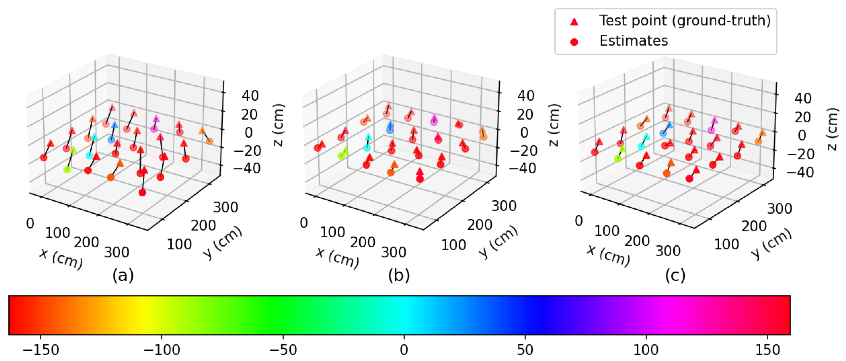
3.2.2. Position Estimation

Here, the proposed scheme’s accuracy is assessed by employing it to localize a mobile node under LOS coverage with the four passive anchor nodes at the test points as illustrated in Figure 2b. The mobile node’s positions are calculated as Taylor series least-squares (TSLS) solutions from the range values obtained using the three ranging schemes in Section 3.2.1. Figure 4 shows estimated positions of the mobile node from AltDS-TWR (w/o Antenna Delay), AltDS-TWR (w/Antenna Delay), and the proposed scheme. From Figure 4b,c, we can see that the estimated positions from AltDS-TWR (w/Antenna Delay) and the proposed scheme are fairly close to the ground-truths (which indicates the test points) as compared to AltDS-TWR (w/o Antenna Delay). Moreover as seen in Figure 4b,c, the localization performance of the proposed scheme is comparatively similar to that of AltDS-TWR (w/Antenna Delay). Table 3 provides a summary of the localization errors for the three schemes.
The RMSEs (unit: cm) of the estimated xyz-coordinates and positions of the mobile node from AltDS-TWR (w/o Antenna Delay), AltDS-TWR (w/Antenna Delay), and the proposed scheme are provided in Table 3. For AltDS-TWR (w/o Antenna Delay), the maximum RMSEs of the estimated xyz-coordinates are 18, 19.83, and 23.6, and the minimum RMSEs of the estimated xyz-coordinates are 2.05, 2.9, and 10.83. For AltDS-TWR (w/Antenna Delay), the maximum RMSEs of the estimated xyz-coordinates are 11.24, 8.59, and 11, and the minimum RMSEs of the estimated xyz-coordinates are 0.91, 0.28, and 0.35. For the proposed scheme, the maximum RMSEs of the estimated xyz-coordinates are 14.6, 10.84, and 11.63, and the minimum RMSEs of the estimated xyz-coordinates are 1.98, 1.96, and 3.88. The average RMSEs of the estimated xyz-coordinates for all of the test points in Table 3 from AltDS-TWR (w/o Antenna Delay) are 11.28, 9.24, and 17.2, from AltDS-TWR (w/Antenna Delay) are 5.47, 5.81, and 6.07, and from the proposed scheme are 7.99, 6.97, and 8.36. These analyses of the data enable us to conclude that the proposed scheme and AltDS-TWR (w/Antenna Delay) display an acceptable performance improvement for estimating all three coordinates of the mobile node positioned at the test points.
Moreover, from Table 3, the maximum RMSEs for estimated positions are 27.34, 12.87, and 16.2, while the minimum RMSEs are 11.89, 7.14, and 9.75 for AltDS-TWR (w/o Antenna Delay), AltDS-TWR (w/Antenna Delay), and the proposed scheme, respectively. The RMSEs of AltDS-TWR (w/Antenna Delay) and the proposed scheme are significantly reduced compared to AltDS-TWR (w/o Antenna Delay) for all the test points. Here, the average RMSEs of all test points in Table 3 from the three schemes are 23.43, 10.73, and 14.07, respectively, which indicate an average improvement of 12.7 and 9.36 over AltDS-TWR (w/o Antenna Delay). When compared to AltDS-TWR (w/o Antenna Delay), AltDS-TWR (w/Antenna Delay) has an average RMSE reduction of approximately 54 % and the proposed scheme has an average RMSE reduction of approximately 39.96 % . These findings show that AltDS-TWR (w/Antenna Delay) and the proposed scheme can effectively localize the mobile node positioned at the test points. Furthermore, from the results in Figure 4 and Table 3, the significance of the proposed scheme is noticeable as it can achieve comparable performance improvement over AltDS-TWR (w/o Antenna Delay) despite no knowledge of the UWB nodes’ antenna delay values.
From these analyses of the test results, we can conclude that the proposed scheme can effectively estimate the range and position of mobile nodes within centimeter-level accuracy in UWB-based RTLSs without the requirement of dedicated standalone antenna delay measurement procedures. This provision would be desirable to exploit the plug-and-play features of ideal UWB-based RTLSs to expand the service to new mobile nodes entering the networks without the necessity to carry out their antenna delay calibration. Moreover, the proposed scheme is shown to be relatively the most air efficient as it requires a limited number of signaling messages during ranging, and through the provision of simultaneous ranging, it can further increase the serviceable capability of the RTLSs. Finally, in Table 4, we summarize and compare the proposed scheme with other state-of-the-art TWR schemes in terms of some basic desirable features of UWB-based RTLSs.

4. Conclusions

In this paper, we propose a novel ranging scheme for UWB-based RTLSs that performs simultaneous range measurements of a mobile node with several anchor nodes while also compensating for the error due to the antenna delays. The provision of simultaneous ranging requires limited air-time occupancy and makes the scheme more air efficient. Further, the ranges between UWB node pairs are estimated without requiring the knowledge or measurement of antenna delays, which simplifies the UWB-based RTLS. From an experiment to compare the localization accuracy of a mobile node at test points, we show that the proposed scheme can achieve performance within the same order of magnitude compared to that of the state-of-the-art TWR method (where antenna delay values of each UWB node were pre-measured and used during range estimations). The numerical results from the experiment also show that the proposed scheme, when compared to the state-of-the-art TWR method (where antenna delay values of each UWB node were not considered during range estimations), provides relative RMSEs improvement for range and position estimations of approximately 54.52 % and 39.96 % , respectively. It signifies that the proposed scheme provides comparable performance in range and position estimations while eliminating the requirement of dedicated standalone antenna delay measurement procedures of UWB nodes. The findings demonstrate that the proposed scheme can simplify the measurement procedures while also maintaining an effective UWB-based RTLS.
For future work, the current experimental setup could be extended to access the performance of the proposed scheme in NLOS conditions. Suitable NLOS mitigation techniques available in literature [38,39,40] should be studied and applied during TOFs estimation to maintain LOS-equivalent performance and robust ranging in such conditions.

Author Contributions

Conceptualization, S.S. and L.W.; methodology, S.S. and L.W.; software, S.S., S.C., R.U., A.P. and M.Z.S.; validation, S.S. and L.W.; formal analysis, S.S., P.V., W.S. and L.W.; investigation, S.S.; resources, S.S., P.V., W.S. and L.W.; data curation, S.S., S.C., R.U., A.P. and M.Z.S.; writing—original draft preparation, S.S.; writing—review and editing, S.S., S.C., R.U., A.P., M.Z.S., P.V., W.S. and L.W.; visualization, S.S. and L.W.; supervision, P.V., W.S. and L.W.; project administration, P.V., W.S. and L.W.; funding acquisition, P.V., W.S. and L.W. All authors have read and agreed to the published version of the manuscript.

Funding

This research is funded by Thailand Science Research and Innovation Fund Chulalongkorn University (CU_FRB65_ind (12)_160_21_26).

Institutional Review Board Statement

Not applicable.

Informed Consent Statement

Not applicable.

Data Availability Statement

Not applicable.

Acknowledgments

This research project is supported by the Second Century Fund (C2F), Chulalongkorn University, Thailand.

Conflicts of Interest

The authors declare no conflict of interest.

References

  1. Sharma, L.; Javali, A.; Nyamangoudar, R.; Priya, R.; Mishra, P.; Routray, S.K. An update on location based services: Current state and future prospects. In Proceedings of the 2017 International Conference on Computing Methodologies and Communication (ICCMC), Erode, India, 18–19 July 2017; pp. 220–224. [Google Scholar] [CrossRef]
  2. Usman, M.; Asghar, M.R.; Ansari, I.S.; Granelli, F.; Qaraqe, K.A. Technologies and Solutions for Location-Based Services in Smart Cities: Past, Present, and Future. IEEE Access 2018, 6, 22240–22248. [Google Scholar] [CrossRef]
  3. Yassin, A.; Nasser, Y.; Awad, M.; Al-Dubai, A.; Liu, R.; Yuen, C.; Raulefs, R.; Aboutanios, E. Recent Advances in Indoor Localization: A Survey on Theoretical Approaches and Applications. IEEE Commun. Surv. Tutor. 2017, 19, 1327–1346. [Google Scholar] [CrossRef] [Green Version]
  4. Zafari, F.; Gkelias, A.; Leung, K.K. A Survey of Indoor Localization Systems and Technologies. IEEE Commun. Surv. Tutor. 2019, 21, 2568–2599. [Google Scholar] [CrossRef] [Green Version]
  5. Mendoza-Silva, G.M.; Torres-Sospedra, J.; Huerta, J. A Meta-Review of Indoor Positioning Systems. Sensors 2019, 19, 4507. [Google Scholar] [CrossRef] [PubMed] [Green Version]
  6. Shum, L.C.; Faieghi, R.; Borsook, T.; Faruk, T.; Kassam, S.; Nabavi, H.; Spasojevic, S.; Tung, J.; Khan, S.S.; Iaboni, A. Indoor Location Data for Tracking Human Behaviours: A Scoping Review. Sensors 2022, 22, 1220. [Google Scholar] [CrossRef]
  7. Gandhi, G.M.; Rama, P. GPS based Multi-hop Communication with Localization in Subterranean Wireless Sensor Networks. Procedia Comput. Sci. 2015, 57, 1189–1198. [Google Scholar] [CrossRef] [Green Version]
  8. Du, H.; Zhang, C.; Ye, Q.; Xu, W.; Kibenge, P.L.; Yao, K. A hybrid outdoor localization scheme with high-position accuracy and low-power consumption. EURASIP J. Wirel. Commun. Netw. 2018, 2018, 4. [Google Scholar] [CrossRef] [Green Version]
  9. Ferreira, A.F.G.; Fernandes, D.M.A.; Catarino, A.P.; Monteiro, J.L. Localization and Positioning Systems for Emergency Responders: A Survey. IEEE Commun. Surv. Tutor. 2017, 19, 2836–2870. [Google Scholar] [CrossRef]
  10. Almansa, C.M.; Shule, W.; Queralta, J.P.; Westerlund, T. Autocalibration of a Mobile UWB Localization System for Ad-Hoc Multi-Robot Deployments in GNSS-Denied Environments. CoRR 2020. [Google Scholar] [CrossRef]
  11. Simon, T. Indoor Positioning and Navigation. Sensors 2021, 21, 4793. [Google Scholar] [CrossRef]
  12. IEEE 802.15.4a; IEEE Standard for Information Technology—Local and Metropolitan Area Networks—Specific Requirements—Part 15.4: Wireless Medium Access Control (MAC) and Physical Layer (PHY) Specifications for Low-Rate Wireless Personal Area Networks (WPANs): Amendment 1: Add Alternate PHYs. Technical Report; IEEE: Piscataway, NJ, USA, 2007.
  13. Karapistoli, E.; Pavlidou, F.; Gragopoulos, I.; Tsetsinas, I. An overview of the IEEE 802.15.4a Standard. IEEE Commun. Mag. 2010, 48, 47–53. [Google Scholar] [CrossRef]
  14. IEEE Std 802.15.4-2011 (Revision of IEEE Std 802.15.4-2006); IEEE Standard for Local and Metropolitan Area Networks—Part 15.4: Low-Rate Wireless Personal Area Networks (LR-WPANs). IEEE: Piscataway, NJ, USA, 2011; pp. 1–314. [CrossRef]
  15. IEEE 802.15.4z-2020; IEEE 802.15.4z-2020—IEEE Standard for Low-Rate Wireless Networks–Amendment 1: Enhanced Ultra Wideband (UWB) Physical Layers (PHYs) and Associated Ranging Techniques. Technical Report; IEEE: Piscataway, NJ, USA, 2020.
  16. Yang, J.; Chen, Y. Indoor Localization Using Improved RSS-Based Lateration Methods. In Proceedings of the 2009 IEEE Global Telecommunications Conference, Honolulu, HI, USA, 30 November–4 December 2009; pp. 1–6. [Google Scholar] [CrossRef]
  17. Seco, F.; Jimenez, A.R.; Prieto, C.; Roa, J.; Koutsou, K. A survey of mathematical methods for indoor localization. In Proceedings of the 2009 IEEE International Symposium on Intelligent Signal Processing, Budapest, Hungary, 26–28 August 2009; pp. 9–14. [Google Scholar] [CrossRef]
  18. Liu, H.; Darabi, H.; Banerjee, P.; Liu, J. Survey of Wireless Indoor Positioning Techniques and Systems. IEEE Trans. Syst. Man Cybern. Part C (Appl. Rev.) 2007, 37, 1067–1080. [Google Scholar] [CrossRef]
  19. Alarifi, A.; Al-Salman, A.; Alsaleh, M.; Alnafessah, A.; Al-Hadhrami, S.; Al-Ammar, M.A.; Al-Khalifa, H.S. Ultra Wideband Indoor Positioning Technologies: Analysis and Recent Advances. Sensors 2016, 16, 707. [Google Scholar] [CrossRef] [PubMed] [Green Version]
  20. Hach, R. Symmetric double side two way ranging. In Contribution to IEEE 802.15.4A, IEEE P802.15 Work. Group for Wireless Pers. Area Netw. (WPAN), Doc. IEEE P.802.15-05-0334-00-004a; Technical Report; IEEE Computer Society: Washington, DC, USA, 2005. [Google Scholar]
  21. Jiang, Y.; Leung, V.C.M. An Asymmetric Double Sided Two-Way Ranging for Crystal Offset. In Proceedings of the 2007 International Symposium on Signals, Systems and Electronics, Bremen, Germany, 30 July–2 August 2007; pp. 525–528. [Google Scholar] [CrossRef]
  22. Neirynck, D.; Luk, E.; McLaughlin, M. An alternative double-sided two-way ranging method. In Proceedings of the 2016 13th Workshop on Positioning, Navigation and Communications (WPNC), Bremen, Germany, 19–20 October 2016; pp. 1–4. [Google Scholar] [CrossRef]
  23. Wu, Y.; Chaudhari, Q.; Serpedin, E. Clock Synchronization of Wireless Sensor Networks. IEEE Signal Process. Mag. 2011, 28, 124–138. [Google Scholar] [CrossRef]
  24. Lian Sang, C.; Adams, M.; Hörmann, T.; Hesse, M.; Porrmann, M. Numerical and Experimental Evaluation of Error Estimation for Two-Way Ranging Methods. Sensors 2019, 19, 616. [Google Scholar] [CrossRef] [Green Version]
  25. Shah, S.; Demeechai, T. Multiple Simultaneous Ranging in IR-UWB Networks. Sensors 2019, 19, 5415. [Google Scholar] [CrossRef] [Green Version]
  26. Laadung, T.; Ulp, S.; Alam, M.M.; Moullec, Y.L. Novel Active-Passive Two-Way Ranging Protocols for UWB Positioning Systems. IEEE Sens. J. 2022, 22, 5223–5237. [Google Scholar] [CrossRef]
  27. Decawave Limited. APS011 Application Note, Sources of Error in DW1000 Based Two-Way Ranging (TWR) Schemes; Decawave: Dublin, Ireland, 2014. [Google Scholar]
  28. Decawave Limited. APS014 Application Note, Antenna Delay Calibration of DW1000-Based Products and Systems; Decawave: Dublin, Ireland, 2018. [Google Scholar]
  29. Basiri, A.; Lohan, E.S.; Moore, T.; Winstanley, A.; Peltola, P.; Hill, C.; Amirian, P.; Figueiredo e Silva, P. Indoor location based services challenges, requirements and usability of current solutions. Comput. Sci. Rev. 2017, 24, 1–12. [Google Scholar] [CrossRef] [Green Version]
  30. Horváth, K.A.; Ill, G.; Milánkovich, Á. Calibration method of antenna delays for UWB-based localization systems. In Proceedings of the 2017 IEEE 17th International Conference on Ubiquitous Wireless Broadband (ICUWB), Salamanca, Spain, 12–15 September 2017; pp. 1–5. [Google Scholar]
  31. Gui, X.; Guo, S.; Chen, Q.; Han, L. A New Calibration Method of UWB Antenna Delay Based on the ADS-TWR. In Proceedings of the 2018 37th Chinese Control Conference (CCC), Wuhan, China, 25–27 July 2018; pp. 7364–7369. [Google Scholar]
  32. Shah, S.; Chaiwong, K.; Kovavisaruch, L.O.; Kaemarungsi, K.; Demeechai, T. Antenna Delay Calibration of UWB Nodes. IEEE Access 2021, 9, 63294–63305. [Google Scholar] [CrossRef]
  33. Piavanini, M.; Barbieri, L.; Brambilla, M.; Cerutti, M.; Ercoli, S.; Agili, A.; Nicoli, M. A Calibration Method for Antenna Delay Estimation and Anchor Self-Localization in UWB Systems. In Proceedings of the 2022 IEEE International Workshop on Metrology for Industry 4.0 & IoT (MetroInd4.0&IoT), Trento, Italy, 7–9 June 2022; pp. 173–177. [Google Scholar] [CrossRef]
  34. Shah, S.; Kovavisaruch, L.o.; Kaemarungsi, K.; Demeechai, T. Node Calibration in UWB-Based RTLSs Using Multiple Simultaneous Ranging. Sensors 2022, 22, 864. [Google Scholar] [CrossRef]
  35. Decawave Limited. Decawave DWM1001 Datasheet; Decawave: Dublin, Ireland, 2017. [Google Scholar]
  36. Segger Microcontroller. Segger Embedded Studio. Available online: https://www.segger.com/products/development-tools/embedded-studio/ (accessed on 11 December 2022).
  37. Horváth, K.A.; Ill, G.; Milánkovich, Á. Passive extended double-sided two-way ranging with alternative calculation. In Proceedings of the 2017 IEEE 17th International Conference on Ubiquitous Wireless Broadband (ICUWB), Salamanca, Spain, 12–15 September 2017; pp. 1–5. [Google Scholar] [CrossRef]
  38. Yu, K.; Wen, K.; Li, Y.; Zhang, S.; Zhang, K. A Novel NLOS Mitigation Algorithm for UWB Localization in Harsh Indoor Environments. IEEE Trans. Veh. Technol. 2019, 68, 686–699. [Google Scholar] [CrossRef]
  39. Sang, C.L.; Steinhagen, B.; Homburg, J.D.; Adams, M.; Hesse, M.; Ruckert, U. Identification of NLOS and Multi-Path Conditions in UWB Localization Using Machine Learning Methods. Appl. Sci. 2020, 10, 3980. [Google Scholar] [CrossRef]
  40. Park, J.; Nam, S.; Choi, H.; Ko, Y.; Ko, Y. Improving Deep Learning-Based UWB LOS/NLOS Identification with Transfer Learning: An Empirical Approach. Electronics 2020, 9, 1714. [Google Scholar] [CrossRef]
Figure 1. Schematic diagram of a TWR session. Mobile node M transmits the first and third sensing packets, active anchor node A transmits the second sensing packet, and all passive anchor nodes x n from X = { x 1 , x 2 , , x N } , n { 1 , , N } listen to the three sensing packets. t i Tx ( k ) and t i Rx ( k ) respectively denotes the transmission and reception timestamp values of the k-th packet reported by node i, and P i denotes the reception time difference of node i.
Jsan 12 00001 g001
Figure 2. (a) Experimental environment. (b) Experimental layout (unit: cm). The positions of the active and passive anchor nodes, and the test points for the mobile node.
Jsan 12 00001 g002
Figure 3. Comparison of RMSEs of the estimated ranges from the three ranging schemes.
Jsan 12 00001 g003
Figure 4. Estimated positions of the mobile node for the three ranging schemes: (a) AltDS-TWR (w/o Antenna Delay), (b) AltDS-TWR (w/Antenna Delay), and (c) Proposed.
Jsan 12 00001 g004
Table 1. Comparison of the proposed ranging scheme’s air-time occupancy for N passive anchor nodes in a UWB network.
Ranging SchemeAir-Time Occupancy
(Sensing Packets)
Required Number of
Sensing Packets (for N = 4)
SS-TWR 2 N 8
SDS-TWR 3 N 12
AltDS-TWR 3 N 12
AltDS-TWR&PR44
Proposed33
Table 2. RMSEs comparison of the estimated ranges from AltDS-TWR (w/o Antenna Delay), AltDS-TWR (w/Antenna Delay), and proposed scheme.
Test PointRMSE (cm)
AltDS-TWRAltDS-TWRProposed
(w/o Antenna Delay)(w/Antenna Delay)
T118.965.668.79
T220.035.4210.35
T320.448.119.9
T420.077.998.1
T521.927.189.76
T618.074.967.02
T718.156.759.94
T818.394.718.57
T920.788.6810.07
T1021.558.148.91
T1118.24.487.67
T1220.126.387.53
T1317.884.897.98
T1416.615.979.54
T1520.087.039.43
T1618.916.98.85
T1716.616.829.82
T1816.372.785.92
T1917.833.837.25
T2017.823.826.86
Maximum21.928.6810.35
Minimum16.372.785.92
Average18.936.038.61
Table 3. Comparison of RMSEs of the xyz-coordinates and position estimations of the mobile node from AltDS-TWR (w/o Antenna Delay), AltDS-TWR (w/Antenna Delay), and the proposed scheme.
Test PointRMSE (cm)
AltDS-TWRAltDS-TWRProposed
(w/o Antenna Delay)(w/Antenna Delay)
CoordinatesPositionCoordinatesPositionCoordinatesPosition
x-y-z-x-y-z-x-y-z-
T16.8314.9520.15264.985.116.419.596.3810.638.3714.96
T215.2417.9913.2827.063.688.597.411.927.141.9610.0812.51
T317.8712.3714.6126.194.866.577.3410.989.687.649.615.63
T412.6810.3720.8726.537.177.185.3311.469.736.68.9714.79
T517.279.2515.5925.049.395.714.3211.8110.085.9310.3915.64
T63.4119.8318.4627.312.377.076.7110.0310.279.917.516.12
T76.128.3223.625.766.940.285.538.8812.46.688.0116.20
T82.054.4710.8311.893.056.146.679.5714.63.173.8815.44
T910.439.2420.0324.40.916.611112.878.048.637.0413.74
T1014.358.4219.6925.786.688.486.8312.777.314.479.9713.15
T1114.688.8214.322.3111.242.35.2512.625.468.5111.6315.41
T1212.273.5520.9224.518.56.842.2611.149.448.616.9314.54
T139.54.4119.0721.761.967.169.2211.848.744.678.4413.02
T149.792.917.520.263.625.835.99.056.76.139.2212.94
T1513.145.5922.5326.675.578.343.7610.719.398.516.6414.31
T161810.6812.3924.328.224.086.9711.524.110.848.4414.34
T174.8110.410.9515.858.134.230.359.173.087.854.899.75
T183.044.8511.2812.652.854.794.467.141.989.377.1911.98
T1916.7610.618.2926.986.45.77.1111.148.074.89.1413.1
T2017.487.6919.5727.343.025.198.510.417.124.5510.9413.82
Maximum1819.8323.627.3411.248.591112.8714.610.8411.6316.2
Minimum2.052.910.8311.890.910.280.357.141.981.963.889.75
Average11.289.2417.223.435.475.816.0710.737.996.978.3614.07
Table 4. Comparison of the proposed scheme to other state-of-the-art TWR schemes in terms of some basic desirable features of UWB-based RTLSs.
Ranging SchemeClock
Synchronization
Air EfficientSimultaneous
Ranging
Signaling Messages
(Constrained Reply-Delay Time)
Antenna Delay
Calibration
SS-TWRNot requiredNoNoNoRequired
SDS-TWRNot requiredNoNoYesRequired
AltDS-TWRNot requiredNoNoNoRequired
AltDS-TWR&PRNot requiredYesYesNoRequired
ProposedNot requiredYesYesNoNot required
Disclaimer/Publisher’s Note: The statements, opinions and data contained in all publications are solely those of the individual author(s) and contributor(s) and not of MDPI and/or the editor(s). MDPI and/or the editor(s) disclaim responsibility for any injury to people or property resulting from any ideas, methods, instructions or products referred to in the content.

