Article

Automatic Generation of 3D Indoor Navigation Networks from Building Information Modeling Data Using Image Thinning

1
School of Electrical and Information Engineering, Beijing University of Civil Engineering and Architecture, Beijing 100044, China
2
Beijing Key Laboratory of Intelligent Processing for Building Big Data, Beijing University of Civil Engineering and Architecture, Beijing 100044, China
*
Author to whom correspondence should be addressed.
These authors contributed equally to this work.
ISPRS Int. J. Geo-Inf. 2023, 12(6), 231; https://doi.org/10.3390/ijgi12060231
Submission received: 5 April 2023 / Revised: 10 May 2023 / Accepted: 1 June 2023 / Published: 5 June 2023

Abstract

:
Navigation networks are a common form of indoor map that provide the basis for a wide range of indoor location-based services, intelligent tasks for indoor robots, and three-dimensional (3D) geographic information systems. The majority of current indoor navigation networks are manually modeled, resulting in a laborious and fallible process. Building Information Modeling (BIM) captures design information, allowing for the automated generation of indoor maps. Most existing BIM-based navigation systems for floor-level wayfinding rely on well-defined spatial semantics, and do not adapt well to buildings with irregular 3D shapes, which can make cross-floor path generation difficult. This research introduces an innovative approach to generating 3D indoor navigation networks automatically from BIM data using image thinning, which is referred to as GINIT. Firstly, GINIT extracts grid-based maps for floors from BIM data using only two types of semantics, i.e., slabs and doors. Secondly, GINIT captures cross-floor paths from building components by projecting 3D forms onto a 2D image, thinning the 2D image to capture the 2D projection path, and crossing over the 2D routes with 3D routes to restore the 3D path. Finally, to demonstrate the effectiveness of GINIT, experiments were conducted on three real-world multi-floor buildings, evaluating its performance across eight types of cross-layer architectural component. GINIT overcomes the dependency of space definitions in current BIM-based navigation network generation schemes by introducing image thinning. Due to the adaptability of navigation image thinning to any binary image, GINIT is capable of generating navigation networks from building components with diverse 3D shapes. Moreover, the current studies on indoor navigation network extraction mainly use geometry theory, while this study is the first to generate 3D indoor navigation networks automatically using image thinning theory. The results of this study will offer a unique perspective and foster the exploration of imaging theory applications of BIM.

1. Introduction

Indoor navigation models, also termed indoor maps, represent geometrical and topological information of the physical environments in buildings. Similar to outdoor maps such as Google maps, indoor navigation models lay the foundation for most indoor location-based services (LBS) [1], e.g., indoor wayfinding [2] and escape path planning during an emergency [3], to name a few. Acting as a primary part of 3D maps, indoor navigation models have garnered widespread attention in the area of 3D geographic information systems (GIS) [4] and have facilitated last-mile car/pedestrian navigation [5]. From the perspective of robots and automation, indoor navigation model extraction is a fundamental problem of autonomous intelligent jobs [6]. The last decade has witnessed extensive studies on indoor navigation networks from a variety of disciplines.
Traditionally, indoor navigation models are generated manually. Initially, users conduct a thorough examination of the indoor spaces of buildings, followed by the creation of indoor navigation models using map-making tools. This approach is strenuous, prone to errors, and time-intensive. This has triggered new demand for the automatic generation of indoor navigation models. Nowadays, Building Information Modeling (BIM) [7] has become a ubiquitous tool in the architecture, engineering, construction, operation, and facility management (AECO/FM) industries. Due to BIM’s ability to systematically capture multi-dimensional computer-aided design (CAD) information, several studies [2,3,8,9,10,11,12] have explored various approaches to automatically extracting indoor navigation models from BIM data. Without a doubt, these efforts could lead to a significant reduction in the cost of indoor map collection and advance research in various areas relating to the indoor environment, such as indoor location-based services (LBS), pathfinding, and autonomous intelligent systems.
Generally, indoor navigation models can be classified into two categories: grid-based maps and topology-based navigation networks (also termed topological maps). Grid-based maps enable accurate, but inefficient, pathfinding. Because the efficiency of a wayfinding algorithm, e.g., A-star [13], diminishes exponentially with an increasing number of cells in a grid-based map, the navigation networks act oppositely, which allows for much more efficient pathfinding. Moreover, they require less storage space and integrate both spatial semantics and geometrical data [9]. Due to the importance of semantics data in wayfinding [14], navigation networks have been extensively employed in navigation services. However, the auto-generation of indoor navigation networks poses a daunting challenge since pedestrians are not constrained to specific routes within buildings.
A comprehensive 3D indoor navigation network encompasses not only floor-level indoor navigation networks, but also inter-floor indoor paths. Therefore, a 3D indoor map comprises both intra-floor indoor navigation networks and inter-floor paths, which facilitate seamless navigation within and between floors of a building [9]. Thus, the challenges of indoor navigation network generation using BIM can be summarized from two aspects.
(1)
Floor-level indoor navigation network generation. Some floor-level indoor navigation network generation schemes based on BIM employ the technologies of visibility graphs (VG) [15] and Medial Axis Transform (MAT) [9,10,16,17,18,19]. Compared with VG-based navigation network models, MAT-based schemes can generate navigation networks, which are more succinct and more consist with common human cognition. Nonetheless, these methods usually require well-defined spatial semantics, i.e., rooms and corridors. When spatial semantics are not provided or the indoor environments are complex with a variety of furniture, these methods fail to work.
(2)
Cross-floor path generation. While previous studies [9,20] have explored generating cross-floor paths from BIM data, these methods may not be easily adaptable to irregular architectural components, e.g., winding stairs and curved ramps. As a result, automatically generating navigation paths from such irregular architectural components remains a challenging task.
To address the challenges of both floor-level and cross-floor navigation network generation, this study proposes an auto-generation of 3D indoor navigation networks from BIM purely using image thinning [21,22], termed GINIT. GINIT generates floor-level indoor navigation networks by thinning the grid-based maps, extracts cross-floor routes from the cross-layer architectural components in the BIM data, and generates paths from cross-floor paths to floor-level navigation networks using an A-star algorithm. The whole process of GINIT is fully automatic and has the following advantages.
(1)
Compared with current BIM-based floor-level navigation network generation schemes, GINIT does not require spatial semantics and can be applied to any indoor environments. GINIT maps and discretizes all the elements on a floor to a 2D plane to generate a grid-based map. Only two types of element need to be defined, namely, slabs and doors. Slabs are passable areas, while doors define a passable route across obstacles. The remaining elements are considered obstacles. This avoids the definition of spaces. On top of this, GINIT generates floor-level indoor navigation networks by thinning the grid-based maps. Since image thinning is adaptive to any binary image, GINIT can extract floor-level navigation networks with any environment. Additionally, the navigation networks generated by GINIT are consistent with human cognition, because image thinning can maintain the shape of passable areas in buildings.
(2)
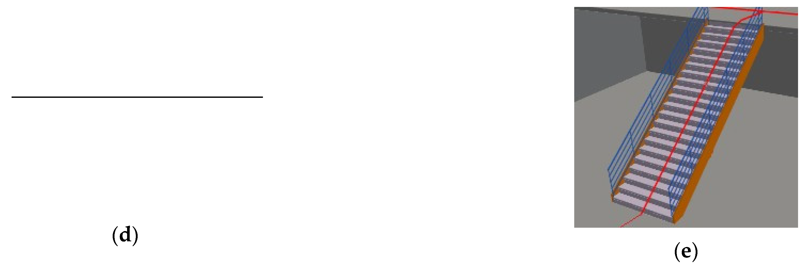
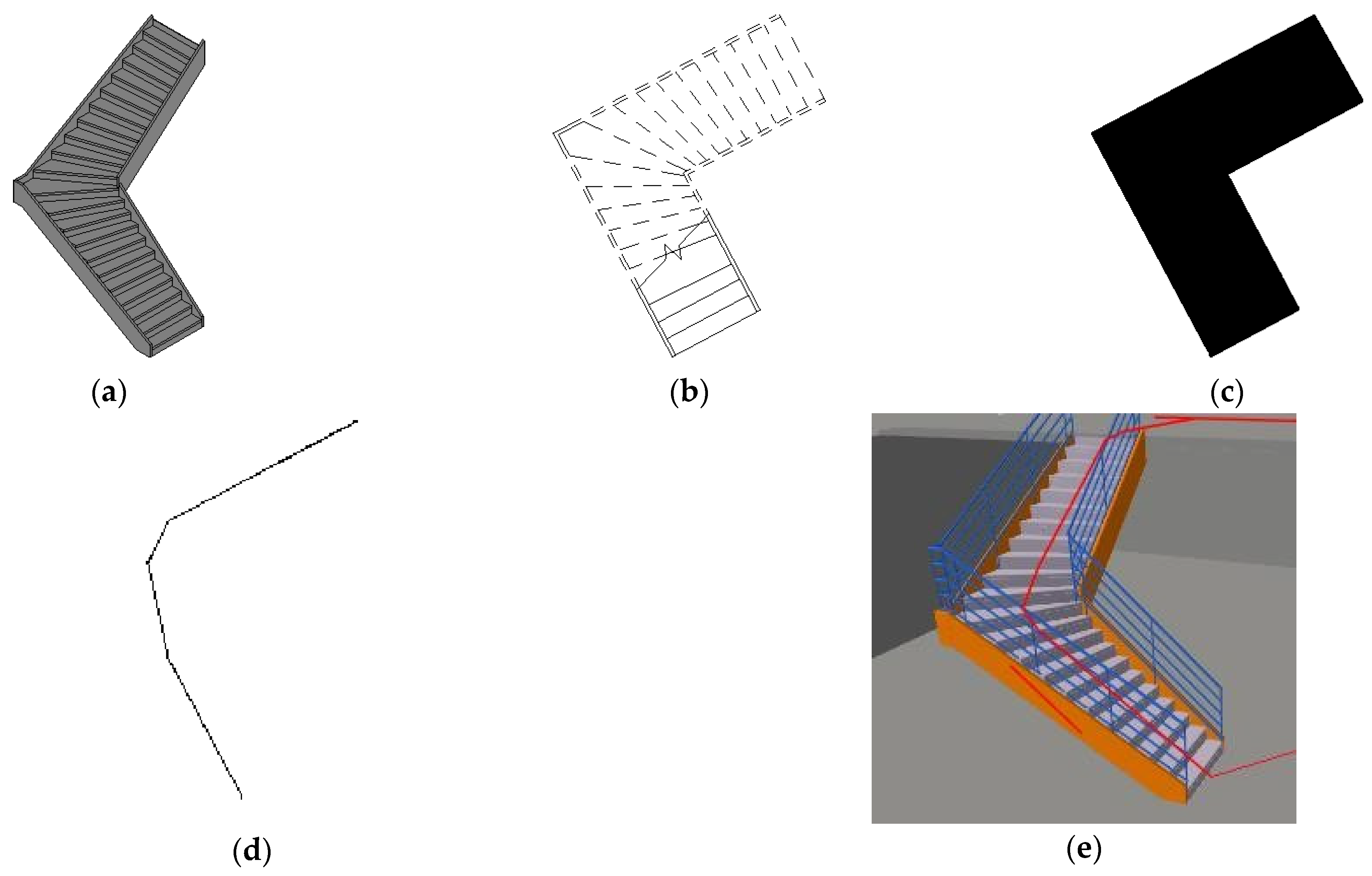
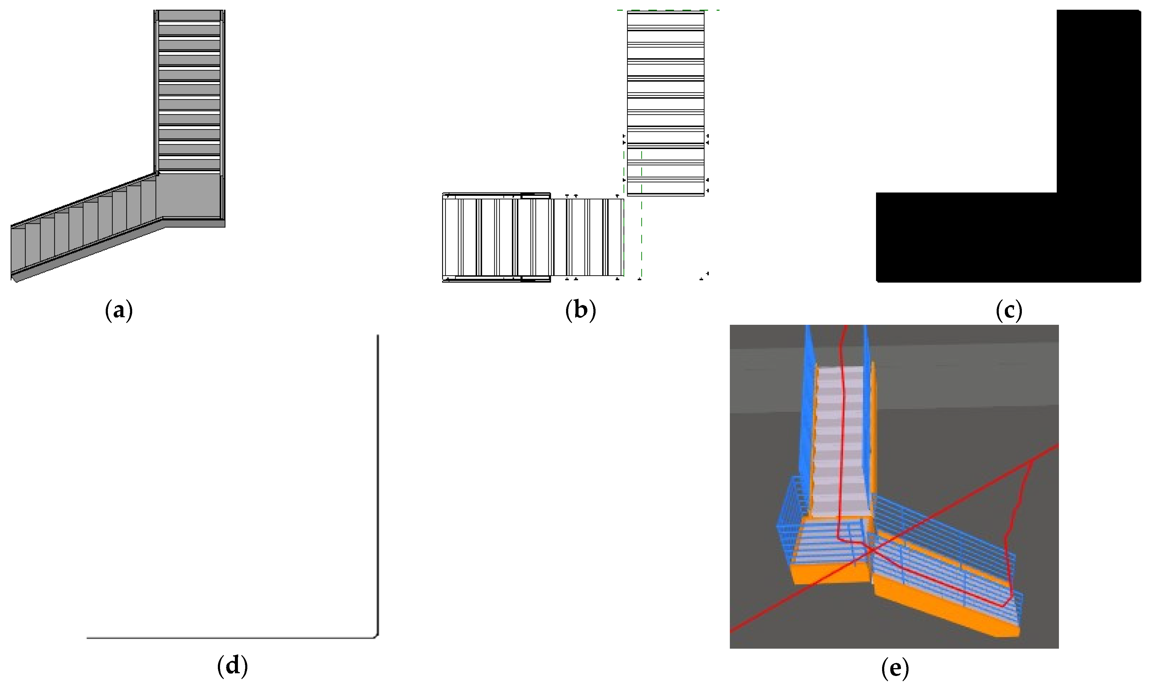
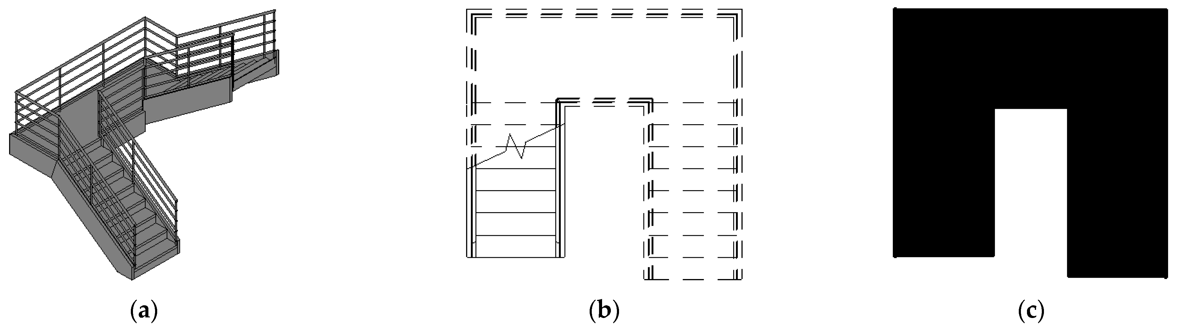
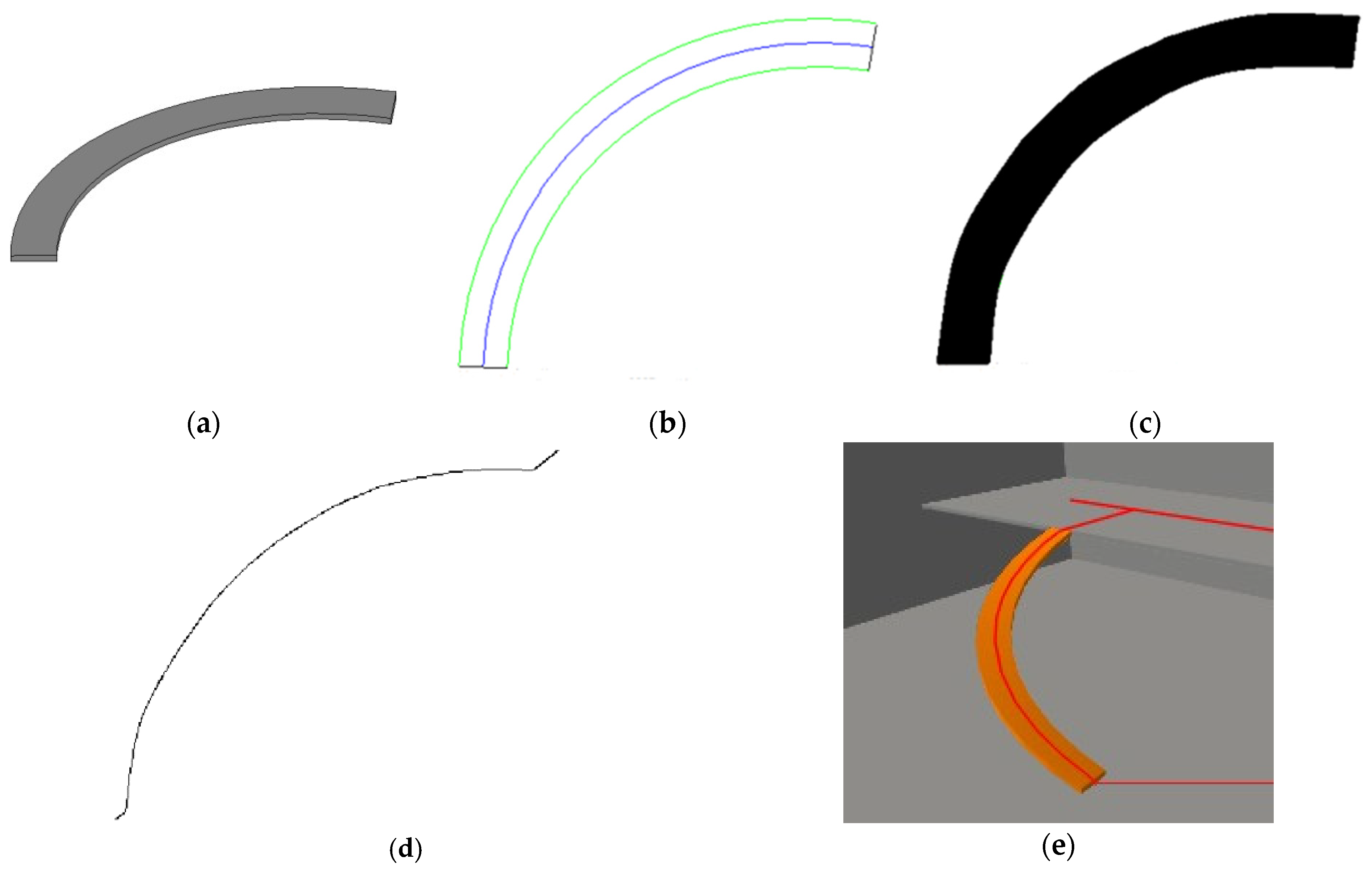
Compared to current BIM-based cross-floor path generation methods, GINIT offers the advantage of being able to extract paths from architectural components with diverse 3D shapes. Similar to the process of generating a cross-floor navigation network, GINIT employs image thinning to project a cross-floor architectural component onto a 2D plane in order to derive a project path. The cross-floor path is then restored by crossing over the projection route using a 3D model. The ability of image thinning to capture lines from any binary image while preserving the shape of the given image allows GINIT to produce cross-floor routes from architectural components with arbitrary 3D shapes.
(3)
The current 3D indoor navigation network generation schemes (VG-/MAT-based schemes) are generally based on the theory of geometry in computer graphics. Instead, GINIT employs a thinning algorithm, another major branch in computer graphics. From this perspective, GINIT extends the applications of the image thinning algorithm to the BIM area and inspires great advancements in the study on BIM with imaging theory.
This paper is structured as follows: Section 2 presents a literature review on generating indoor maps utilizing BIM data; Section 3 briefly explains image thinning and floor-level map generation; Section 4 introduces the proposed cross-floor 3D indoor map generation approach; Section 5 presents the results of experiments conducted to generate 3D indoor maps using GINIT; and Section 6 presents our conclusions.

2. Related Works

Indoor navigation models are the focus of considerable computer science and engineering research, as they serve as the foundation for indoor pathfinding. Indoor maps have also found numerous applications in the AECO/FM sector, as evidenced by the works of [8,9,10,11,12]. With the widespread adoption of BIM, technologies for generating 3D indoor navigation models using BIM data have emerged. In this study, the Industry Foundation Classes (IFC) format is used to represent the BIM model, which is the international standard for BIM [23].
At present, researchers are extensively exploring the automatic generation of 3D indoor navigation models utilizing BIM. The comprehensive 3D indoor navigation model comprises both floor-level models and cross-floor routes.

2.1. The Production of Floor-Level Indoor Maps Utilizing BIM

The floor-layer navigation model is a 2D spatial model representing the indoor environment of a floor. These models can be broadly classified into categories: grid-based maps and topology-based navigation networks.

2.1.1. Grid-Based Navigation Maps

Grid-based maps are commonly represented as occupancy grids, where each cell contains information about whether an obstacle is present or not. This approach facilitates the precise identification of the first and last points in wayfinding tasks. However, grid-based maps are inefficient when executing wayfinding algorithms such as A-star [13].
In 2013, Lin presented a technique for extracting grid-based maps of 3D indoor spaces from BIM [8]. This approach involves collecting both geometric and semantic data of architectural components in the BIM file, discretizing them, and mapping them onto a planar grid to produce a grid-based map. The occupancy of each grid is determined based on whether an architectural component occupies the grid or not.
Grid-based maps are an easy-to-implement approach that enables accurate modeling of complex indoor environments, including position, direction, and distance. The accuracy of a grid-based map can be improved by decreasing the cell size. Nevertheless, using wayfinding algorithms such as A-star to traverse many cells can result in poor performance and scalability issues. As the number of cells increases, the traversal time may increase exponentially, making it difficult to use the grid-based map for large indoor spaces [24]. Although quadtrees [25], PR quadtrees [26], and skip quadtrees [27] mitigate the performance problems to some extent, efforts to improve wayfinding efficiency in a grid-based map with millions of cells are still required.

2.1.2. Topology-Based Navigation Network

A topology-based navigation network is represented by a collection of points and their relationships, indicating feasible routes between them [28]. A point is a consolidated position on a 3D face, and each position is of relevance for establishing an accessible route between two points. Unlike grid-based maps, navigation networks enable efficient computation of the shortest paths. There are several studies on extracting topological maps (e.g., visibility graphs [15], straight skeletons [16], and generalized Voronoi graphs (GVG) [29]).
A VG is composed of a collection of nodes and edges that are visible to each other. A visibility graph models the vertices of obstacles, and the entrances and exits, as visible nodes. It bridges any two nodes with a visible edge, if the edge does not intersect with any object. Visibility graphs can be applied to facilitate some indoor LBS [20,24]. It has two disadvantages: The first challenge is related to the way humans perceive paths [9,30]. The second challenge concerns the exponential growth in the number of edges as the number of visible nodes increases [9,20].
A straight skeleton generates an indoor map by capturing the medial axis of geometric shapes using Medial Axis Transform (MAT) [16,17]. The Straight Medial Axis Transform (S-MAT) algorithm [18] is one of the earliest in this category. However, the S-MAT approach can produce satisfactory results for geometric forms consisting of simple shapes. To enhance the performance of S-MAT, the Modified Medial Axis Transform (M-MAT) approach was introduced [10]. Nevertheless, M-MAT produces unnecessary nodes and bending edges for indoor building components with irregular polygons [9]. Chen et al. [11] opted for an approximate MAT to generate indoor emergency rescue routing. Fu et al. [19] pointed out that these methods struggle to handle rooms with irregular shapes or generate detours. To tackle this challenge, Fu et al. [19] developed a new method named “Improved Generation of Straight Skeletons-based Navigation Networks” to create skeleton-based indoor navigation graph networks. These approaches usually require accurate definition of indoor spaces, i.e., rooms and corridors, regardless of the furniture in a building. If the indoor spaces are not well-defined or the complex indoor environment has to be considered, then these approaches are not applicable. Cheng et al. [12] also considered that MAT-based approaches were not applicable to buildings with large open areas. To address this issue, they proposed a graph-based network using consolidation MAT with VG, thus introducing VG’s limitations.
A generalized Voronoi graph (GVG) constructs indoor maps using a generalized Voronoi diagram (GVD) [29]. Several variations of the GVG have been developed to generate more effective indoor maps. For instance, Delaunay Triangulation (DT) [31] was introduced to avoid the creation of thin triangles and staggering. Additionally, the Improved Geometric Network Model (IGNM) [32] utilizes Constrained Delaunay Triangulation (CDT) to improve upon DT. Teo developed a multiple-purpose geometric network model (MGNM) using CDT to incorporate both outdoor and indoor routes [5]. Recently, Lin and colleagues [9] proposed an intelligent scheme for the generation of indoor topology (iGIT) to facilitate human wayfinding within buildings. GVG-based schemes can be applied to indoor spaces with irregular shapes. However, they usually generate excessive nodes and paths, resulting in more wayfinding time. Additionally, the reported studies also ignore complex environments with different kinds of furniture.
As discussed above, the current schemes employ geometry theory in computer graphics to generate floor-level navigation networks. They usually require well-defined indoor spaces or ignore complex environments. By projecting a 3D architectural component onto a planar image from a top-down view, we create an image that represents the architectural elements on a floor. This image is then converted into an accessible binary format, capturing the passable areas. This study adopts image thinning to obtain a navigation network, which can maintain the shape of a passable area. This solution is totally different from geometry theory-based schemes, because image thinning is another branch of computer graphics.

2.2. The Generation of Cross-Floor Paths Utilizing BIM

A comprehensive 3D indoor map ought to encompass both floor-level and cross-floor paths. Although many studies point out that cross-floor paths are primary components of 3D indoor maps, only a few efforts [9,20] have been made to achieve the auto-generation of cross-floor indoor maps.
Architectural components related to cross-floor indoor maps involve stairs, ramps, and elevators. Most studies oversimplify the generation of cross-floor paths. For example, Xiong et al. [33] simplified cross-floor paths to vertical lines. In MGNM [5], the sequential linking of stair areas was employed to construct a comprehensive vertical route. Tsiliakou and Dimopoulou [34] manually constructed precise stairway routes to facilitate planning. Lin argued that the simplification of cross-floor paths was employed due to the costly and error-prone generation of high-accuracy paths. In the IFC specification, stairs are defined as IfcStair instances and ramps are defined as IfcStair and IfcRamp instances, respectively. i-GIT [9] enables the generation of cross-floor indoor maps from stairs, ramps, and elevators. However, i-GIT can only be applied to architectural components with regular 3D shapes, such as straight stair flights, straight ramps, etc. Considering architectural components with irregular 3D shapes, such as winding stairs and curved ramps, i-GIT fails to obtain cross-floor indoor maps. Lin [20] introduced a method for creating stair paths with high precision, capable of accommodating straight, spiral, and winding stairs. However, Lin’s approach relies on the definitions of the runs and landings of a stair, and cannot be used to extract cross-floor paths in scenarios where runs and landings are absent, e.g., ramps. No existing solutions have been reported for auto-generating cross-floor routes from cross-layer architectural components.
In the realm of GIS, IndoorGML [35] was proposed as an OGC standard for an open data model and XML schema to facilitate the representation and exchange of indoor spatial information. However, the extraction of indoor spatial information from BIM data requires further effort. After a topological network is extracted automatically from a BIM model, it can be converted into IndoorGML format easily.
This study proposes an approach to producing cross-layer indoor maps using the image thinning technique. The scheme is advantageous as it is applied to obtain 3D maps from arbitrary 3D architectural components due to the versatility of image thinning on binary images.

2.3. Image Thinning

Image thinning [21,22] is the morphological operation in image processing that transforms a binary image into a simplified, but topologically equivalent, version of the original image. That is, image thinning aims to obtain a skeleton (or topological skeleton) of a shape that is equidistant to the image’s boundaries. The thinning algorithm takes a binary image, which results in a skeleton that retains the shape and structure of the original image while being reduced to a 1-pixel-wide representation.
Early in 1992, Lam et al. [21] presented a comprehensive survey on thinning methodologies, which were classified into two main categories: iterative pixel-based approaches and non-pixel-based methods. Since image thinning algorithms have been systematically studied, little progress in the past 10 years has been reported. A recent review cited Saeed’s work [36] in 2010, which provided a historical overview of thinning algorithms spanning over 40 years.
Image thinning is crucial for various applications, such as digital image handing, model recognition, and computer vision. This technique is used for tasks such as optical character recognition, visual inspection, fingerprint recognition, and image compression [21]. Additionally, image thinning has been extensively used in life sciences to analyze protein folding [37] and plant morphology at different biological scales [38]. Image thinning is also extensively used to process medical images [39]. This study represents the first attempt to devise a complete 3D indoor map generation scheme using image thinning.

3. Floor-Level Navigation Network Generation

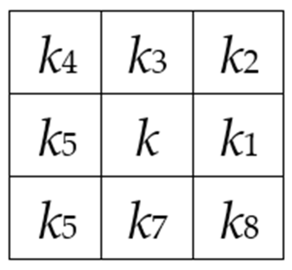
3.1. Zhang–Suen Thinning Algorithm

Thinning algorithms are classified as iterative and non-iterative. While non-iterative algorithms are faster, they may sacrifice accuracy. The Zhang–Suen method [22] was chosen for its accuracy, and used to generate both floor-level indoor maps and top-down-projection topological maps of cross-floor architectural components.
The Zhang–Suen thinning algorithm is a two-pass iterative method, which eliminates pixels from the image through two separate checks in each iteration. The initial set of pixel removal operations begins at the southeast (bottom right) corner of the image, whereas the subsequent set of operations removes pixels from the northwest (top left) corner.
Definition 1 (Connectivity). 
The connectivity of a pixel k, denoted as Ck, is the number of objects that are connected to k.
C k = i S k b b k i · b k i + 1 · b k i + 2
where S = {1, 3, 5, 7}, bk represents the binary value of pixel k, and ki represents the i-th neighbor pixel of k. As shown in Figure 1, the eight neighbors of pixel k are indexed in a counter-clockwise manner, commencing with the pixel located to the right of k.
Definition 2 (Dilatability). 
The Dilatability of pixel k, denoted as Dk, refers to the number of adjacent pixels with a value of 0 around pixel k. Thus, we have:
D k = i { 1,2 , 3,4 , 5,6 , 7,8 } ( 1 b k i )
With the above definitions, the thinning algorithm works in two sub-iterations.
  • Sub-iteration 1: Deletes pixel k while satisfying:
    Ck = 1,
    2 ≤ Dk ≤ 6,
    bk1 × bk3 × bk7 = 0,
    bk1 × bk5 × bk7 = 0.
  • Sub-iteration 2: Deletes pixel k while satisfying:
    Ck = 1,
    2 ≤ Dk ≤ 6,
    bk1 × bk3 × bk5 = 0,
    bk3 × bk5 × bk7 = 0.
Sub-iteration 1 and sub-iteration 2 in the Zhang–Suen thinning algorithm differ in their criteria for deleting pixels. If neither sub-iteration results in the removal of any pixels, the grid thinning process is terminated. The left pixels consist of the final skeleton image of the original image.

3.2. Floor-Level Navigation Network Generation Using Image Thinning

This subsection presents the process of the thinning-based floor-level indoor navigation network abstraction from BIM models.
Thinning-based navigation network generation is built up on the grid-based map. Concretely, navigation networks are captured by thinning grid-based maps. The generation of floor-level navigation networks mainly includes five steps: information extraction from BIM models, grid-based map generation, grid-based map thinning, and topological map enhancement.
(1)
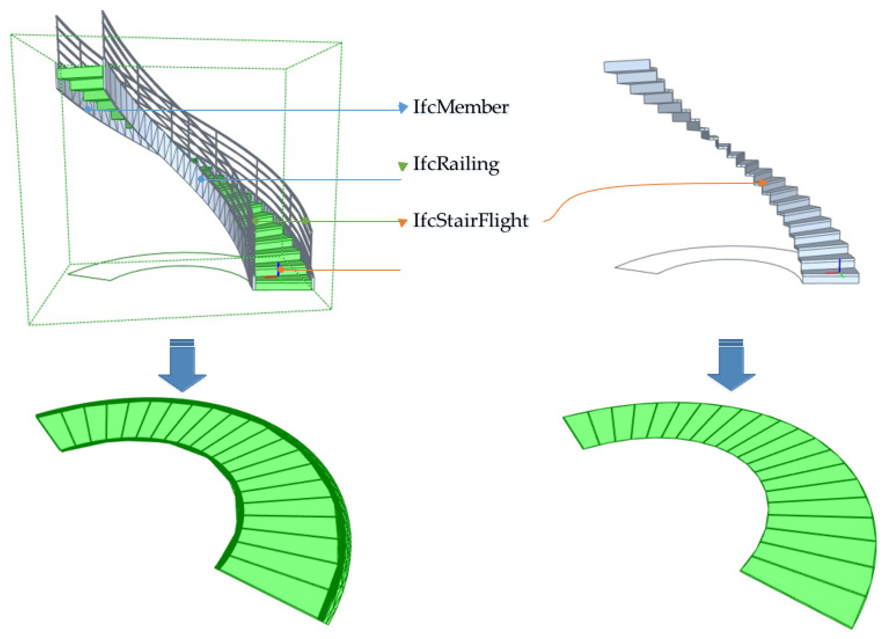
Information extraction from BIM models. The process of information extraction entails extracting essential semantic information from the BIM while ensuring that the amount of data extracted is minimal. The geometric data include all the 3D architectural components. The semantic information is categorized into three types: accessible areas (e.g., slabs), accessible architectural components (e.g., doors), and obstacles. All the architectural components, which are not considered accessible areas and elements, are treated as obstacles.
(2)
Grid-based map generation. The process begins by performing an ‘intersection’ operation on accessible areas with accessible elements and the obstacles to obtain the boundaries of the obstacles. Then, the intersection results are discretized and mapped onto a planar grid, which generates grid-based maps. This study assumes that a navigation network is generated for pedestrians, and the networks mentioned later are all pedestrian navigation networks.
(3)
Grid-based map thinning. A grid-based map can be modeled as a binary image. Because each cell in a grid-based map acts as a pixel in an image, and the accessible status of a cell responds to the 0–1 status of a pixel in a binary image. Thus, image thinning algorithms such as the Zhang–Suen thinning algorithm can be directly applied to thin grid-based maps, which outputs the skeletons of the grid-based maps.
(4)
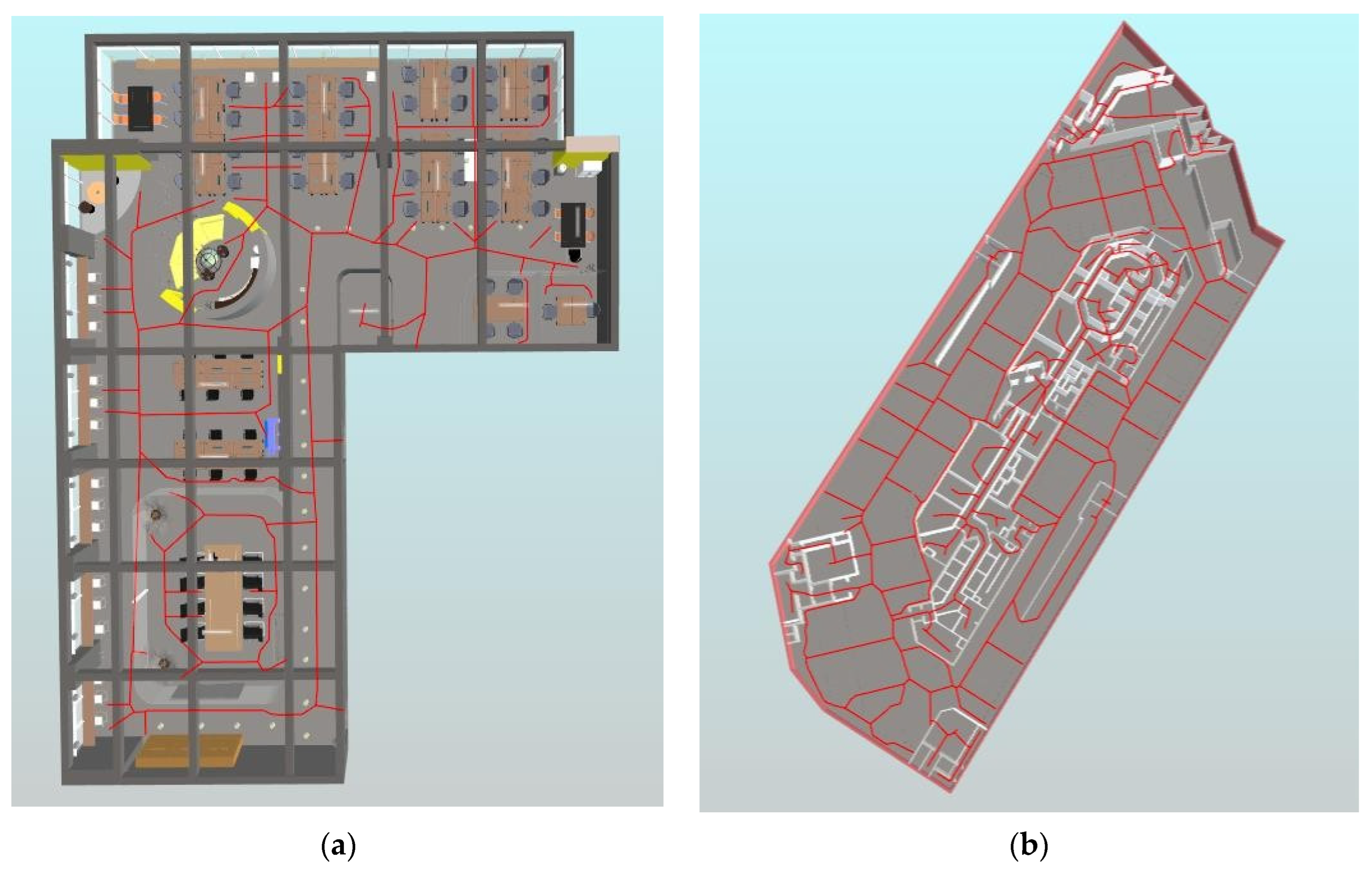
Topological map enhancement. A topological map is used to modeled the cross-floor indoor paths in Section 4. Each entrance of a cross-floor architectural component links to a cell in the generated hybrid map. An A-star algorithm is executed to compute the shortest path from the entrance cell to its nearest cell covered by the topological map. The obtained path is one topological path to the cross-layer architectural component. When topological paths to all entrances of all cross-layer architectural components are generated, the floor-level maps are ready to form a complete 3D indoor map jointly with cross-floor indoor paths.
An example of generating a floor-level navigation network is illustrated in Figure 2. Figure 2a displays a grid-based map that results from projecting and discretizing all architectural components within a floor. In this map, occupied areas are represented by grey grids, while accessible areas are represented by white grids. The navigation network is derived by thinning the accessible grids, which are marked in red on the left-hand side of Figure 2a. The linking of the left grids generates a navigation network, which consists of blue lines in Figure 2b. Since GINIT only relies on the definition of slabs and doors, it overcomes the limitation of space definitions in current BIM-based navigation network generation schemes.

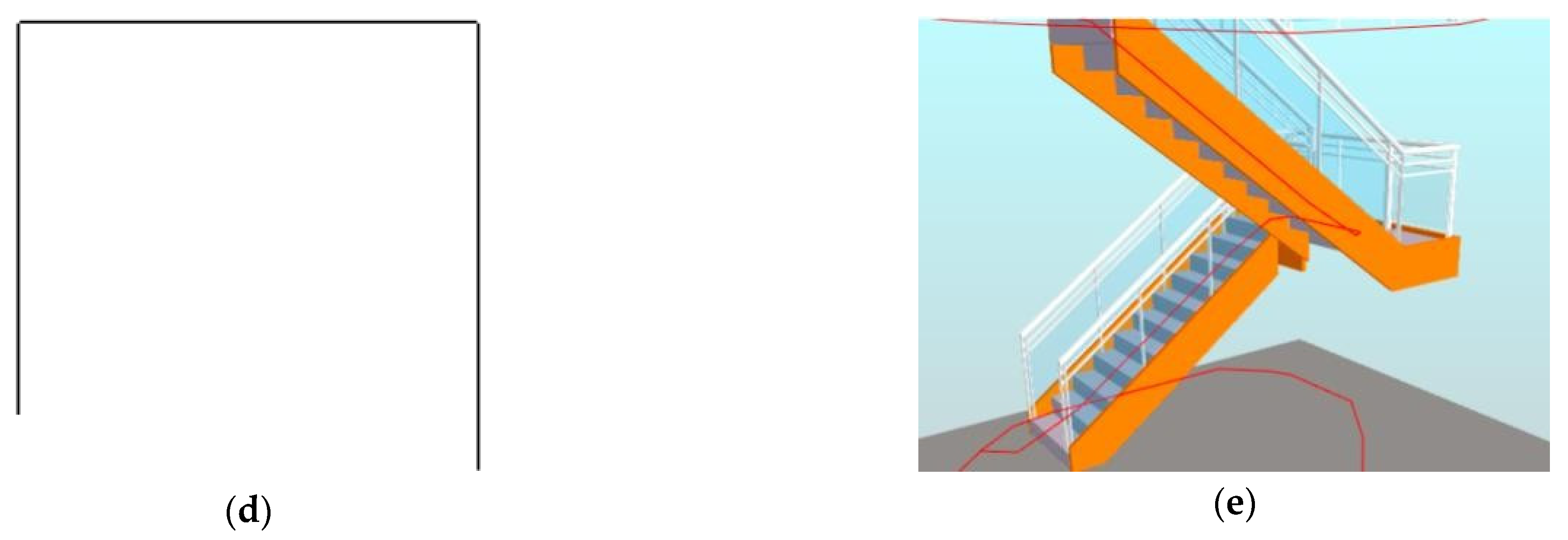
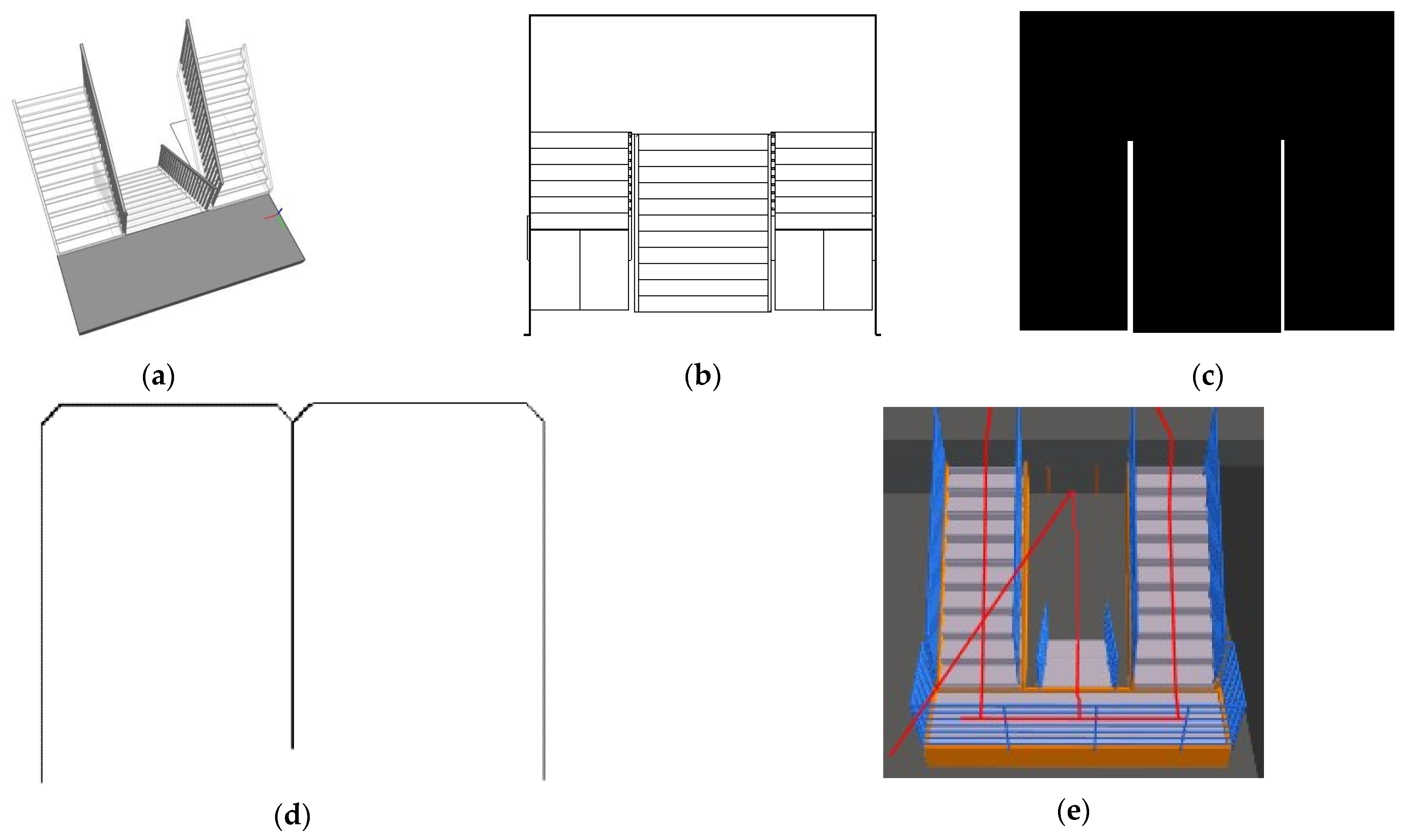
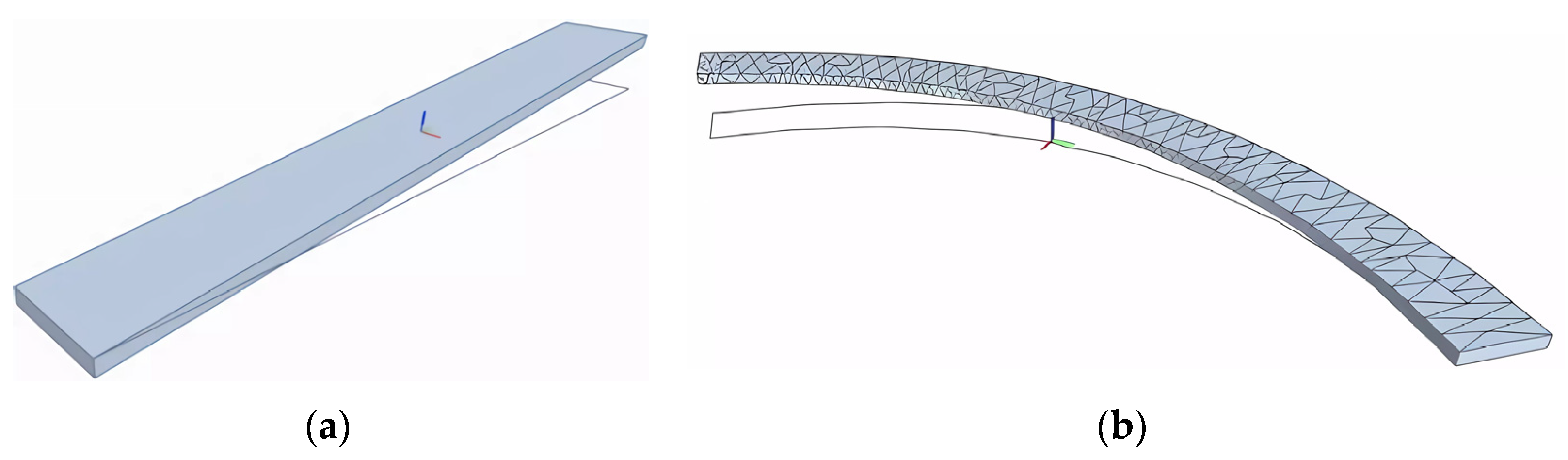
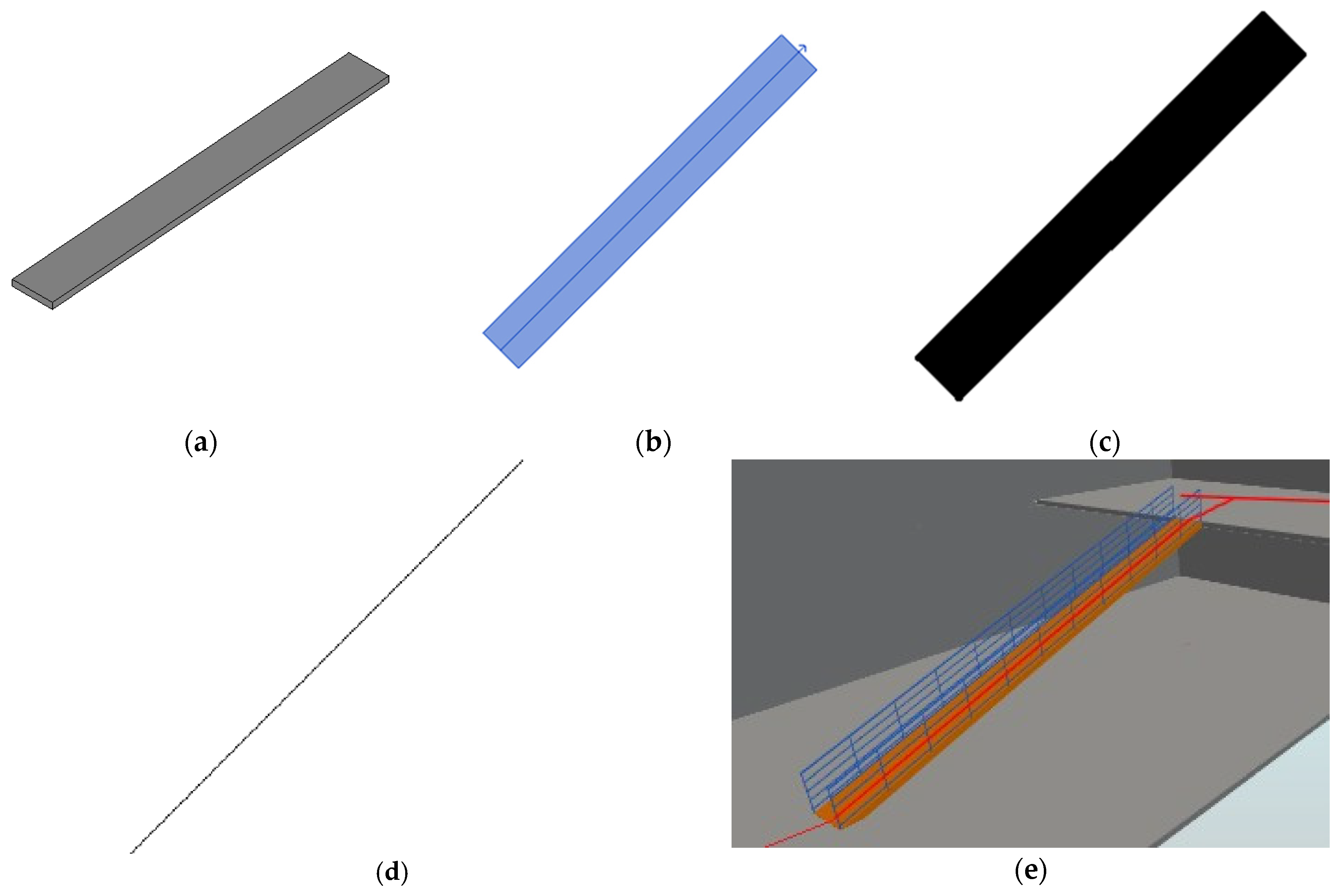
4. Cross-Floor Path Generation Utilizing Image Thinning

A cross-floor 3D indoor map is created by connecting the floor-level maps, using cross-floor architectural components such as stairs and ramps as interfaces. Extracting topological paths from these components is an active way to build the cross-layer indoor map.
Previous studies [9,20] attempted to find and connect midpoints in the cross-layer components to obtain cross-floor paths. However, this approach is only suitable for regular-shaped elements and cannot be applied to irregular-shaped elements such as curved stairs. Auto-production from cross-layer architectural components with irregular forms remains a challenge. In this study, image thinning is used to address this issue.
The production of a navigation network from a cross-layer components with irregular shapes is achieved via GINIT through a three-step process consisting of top-down projection, projection thinning, and projection-BIM intersection. Firstly, the 3D cross-layer architectural component is mapped on to a plane through the top-down view using top-down projection. Next, a navigation network is obtained from the top-down projection using an image thinning algorithm in projection thinning. Finally, the final paths are captured by crossing over the thinning topological network with the 3D shape of the cross-layer element in BIM through the projection–BIM intersection. The complete steps of generating a topological map from a cross-layer architectural component are illustrated in Figure 3.

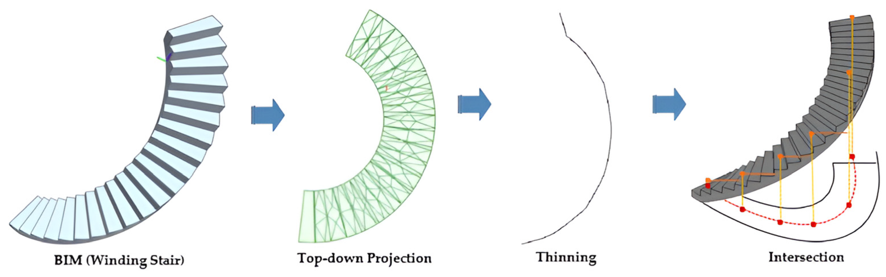
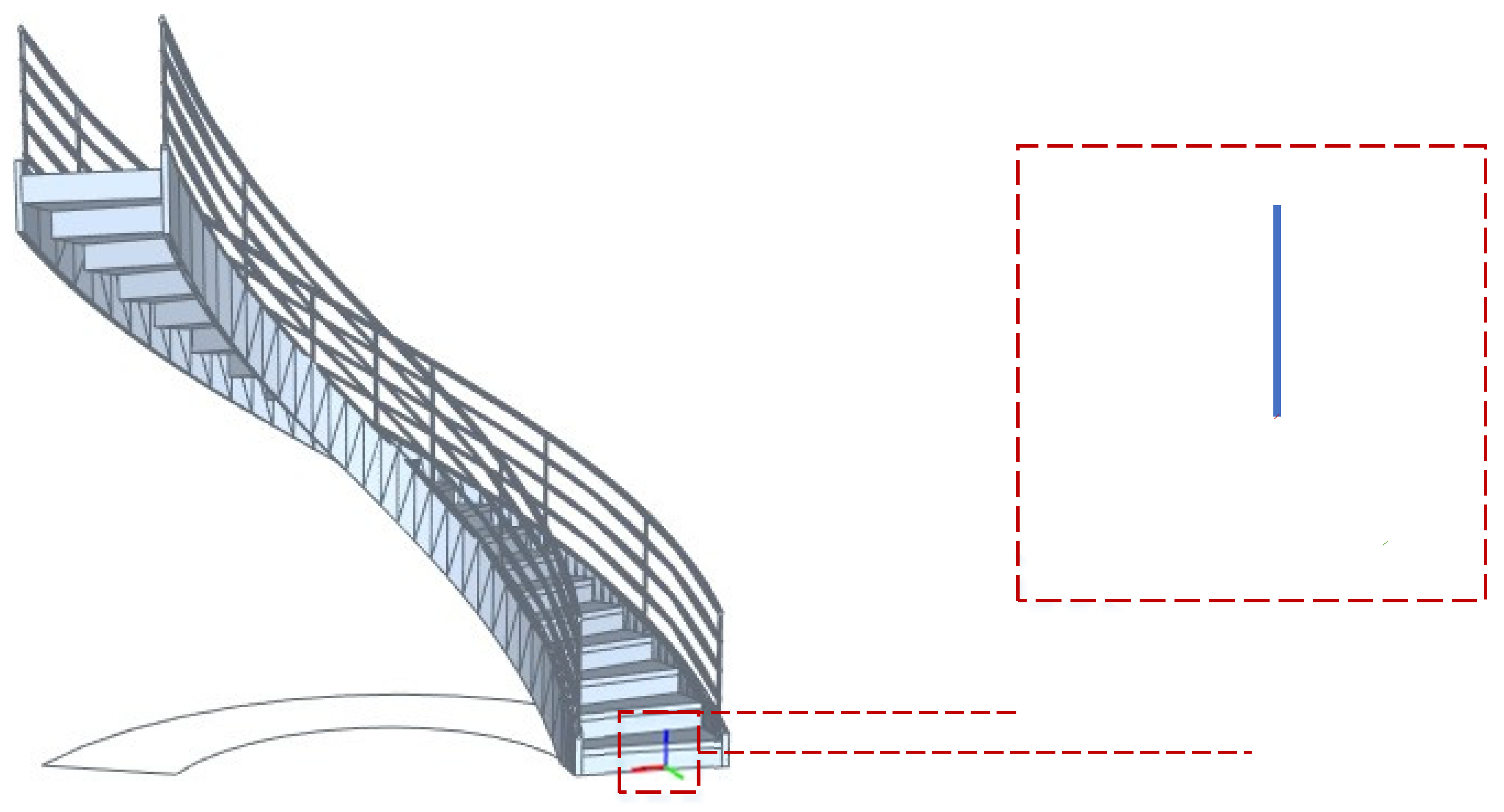
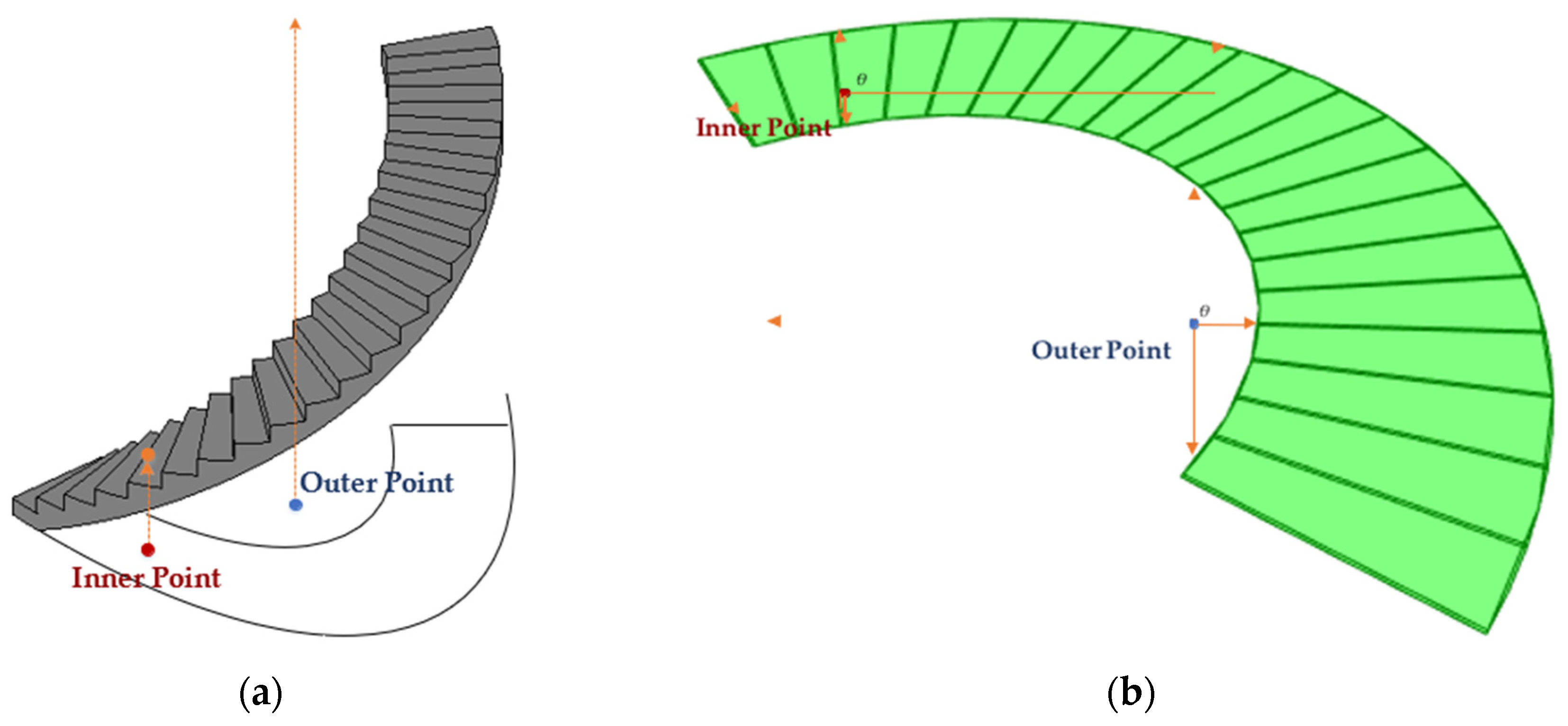
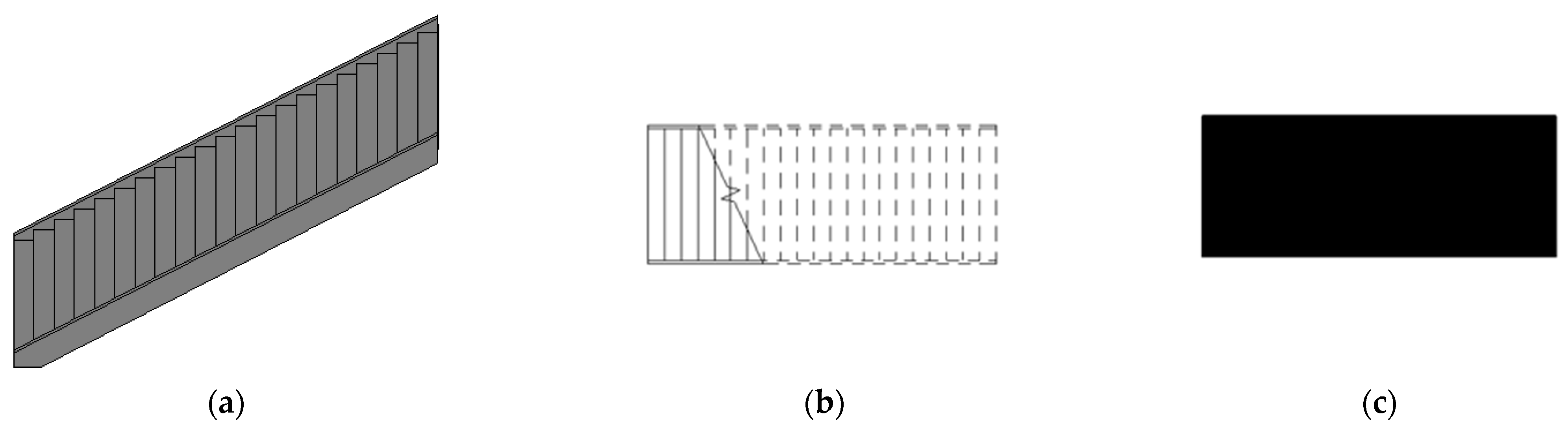
4.1. Top-Down Projection

Top-down projection projects a 3D architectural component onto a planar image from the top-down view. This subsection describes the details of top-down projection.
This subsection begins by defining the coordinate system in the BIM environment to ensure the proper formation of the top-down projection. Figure 4 illustrates the general 3D coordinate system, where the x-axis is horizontal, the y-axis is vertical, and the z-axis represents the depth, depicted by red, blue, and green lines, respectively. By fixing the value of y, the X-Z plane is obtained, while the 2D plane with z = 0 or another fixed value represents the X-Y plane. Similarly, the 2D plane with x = 0 denotes the Y-Z plane, as shown in Figure 4.
The top-down projection involves projecting a 3D cross-floor element onto the X-Z plane. This is achieved by setting y = 0 for all the points, lines, and faces of the 3D object of the cross-layer element, resulting in the X-Z projection of a point (x1, y1, z1) being (x1, 0, z1).
Although top-down projection is easy to implement, some redundant 3D objects should be picked out before the projection to eliminate potential noise. The following is a typical example. A stair is defined as an IfcStair instance in IFC specification. However, an IfcStair instance usually turns into a composite IFC instance, which is composed of most IFC instances. As shown in Figure 5, the IfcStair instance consists of two IfcRailing instances, two IfcMember instances, and one IfcStairFlight instance. When executing a top-down projection of the whole stair (IfcStair instance), the boundaries become complex (bottom-left in Figure 5). The two IfcRailing instances and two IfcMember instances also contain many 3D objects, which can bring noise to the identification of the stair’s topological map. This noise introduced by the IfcMember and IfcRailing instances may also increase the computation complexity and hinder the topological map generation. If both the IfcMember and IfcRailing instances are removed, then a simpler X-Z projection can be obtained (bottom-right in Figure 5). The noisy IFC instances’ elimination can be processed according to the IFC type of each primary element in an architectural component.

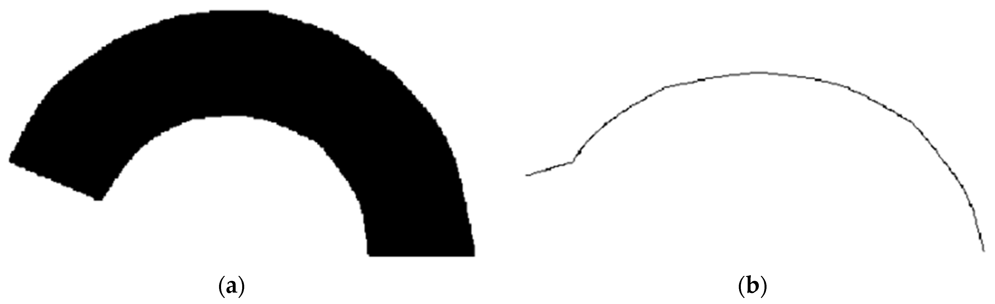
4.2. Projection Thinning

The objective of projection thinning is to utilize an image thinning algorithm to identify the 2D topological network of the cross-floor architectural component’s projection in the X-Z plane. This network is also a projection of the 3D topological network in the X-Z plane. To enable the use of an image thinning algorithm, the 2D projection image of the cross-layer architectural component must be converted into a binary image, with pixels marked as either black or white. This process is referred to as binary filling in this study. Binary filling sets all inner points with a black color and outer points with a white color to generate a binary image. A point is an n × n grid in the X-Z plane. If a point stands inside the boundaries of the projection, then it is an inner point; otherwise, it is an outer point. Figure 4 presents an illustration of a point.
It is not straightforward for the computer to identify the status of a point. Two solutions can be adopted here to judge whether a point is inner or outer, namely, Y extension and X-Z radiation.
Y extension acts in the same way as the occupancy diagnosis in floor-level indoor map generation. If a point is inner, then its extension on the y-axis should intersect with a space in the 3D shapes of the architectural component. Figure 6a exhibits a vivid instance of Y extension. For a given point (x1, 0, z1), a line from (x1, 0, z1) to (x1, y1, z1) is generated, where y1 is set to a large enough value. If the line passes through any faces in the 3D objects of the architectural component, then (x1, 0, z1) is inner; otherwise, it is outer. As shown in Figure 6a, the red point passes through at least one face in the 3D object; thus, it is an inner point. The Y extension has to iteratively search each face of the 3D object for intersections.
Contrary to Y extension, X-Z radiation does not use the 3D objects, but purely uses the 2D projection image. The X-Z radiation emits radiations from a given point. If all the radiations meet at least one line in the projection image, then the given point is an inner point; otherwise, the given point is outer. The red point and blue point in Figure 6b are examples of inner and outer points, respectively. For a given point (x1, 0, z1), a series of lines from (x1, 0, z1) to (x1 + r · cos(), 0, z1 + r · sin()) are generated, where r is a large enough value representing the radius, θ denotes the angle of two neighboring lines, and k = 1, 2, …, 2π/θ is an integer. In Figure 6b, θ = π/2, and k = 1, 2, 3, 4. Since all four lines starting from the red point cross at least one projection line in the image, the red point is an inner point. Contrarily, the line with k = 2 of the blue point intersects with no projection line in the image, the blue point is an outer point.
This study employs Y extension to process the binary filling, because Y extension can be executed using the same algorithm as the grid occupancy process in the floor-level map generation.
With the binary image generated from the binary filling process, the projection thinning obtains the 2D topological map directly using an image thinning algorithm. Similarly, this study also utilizes the Zhang-Suen method to thin the binary image and produce the 2D topological map of a cross-floor building element. Figure 7 presents an example of projection thinning. Figure 7a is the binary image, and Figure 7b is the generated 2D topological map. Intuitively, the 2D topological map is able to represent the route of the winding stair.

4.3. Projection–BIM Intersection

The complete 3D topological map is restored through the projection–BIM intersection process, which involves crossing over the 2D map with the 3D objects present in the BIM.
A line in a 2D topological map consists of sequential points, leading to high computational complexity in both the projection–BIM intersection and the pathfinding. To mitigate this issue, this study firstly reduces the points in the 2D topological map by picking known points in step m. That is, only (l × m)-th (l = 0, 1, 2, …) points are kept in the 2D topological map. A direct line is built for any two left sequential points, i.e., (l × m)-th and [(l + 1) × m]-th (l = 0, 1, 2, …) points. This process reduces the number of original points in the 2D topological map to 1/m times.
To generate the final 3D topological map, each left point pleft = (xleft, 0, zleft) in the topological map is used to construct a line lleft from (xleft, 0, zleft) to (xleft, ym, zleft), where ym is a large value. A 3D face f3D in the cross-layer architectural component is typically represented by three points: (x1, y1, z1), (x2, y2, z2), and (x3, y3, z3). An intersected point pint = (x, yint, z) of pleft and f3D can be computed using an iterative search of all 3D faces in the object. If pleft does not intersect with f3D, then pint = (x, 0, z). A set of intersecting points Pint are obtained in this manner, and the last 3D point in the 3D topological map is the point with the largest y value in Pint, since the accessible point is always at the top.

5. Experiments

We also released GINIT as an online service at building.rickricks.com (accessed on 2 June 2023). Lin et al. [9] used two metrics, namely, availability and accuracy, to assess the performance of the topological map. The availability paths measure the proportion of paths between any two accessible points of interest (POIs) in the building that are successfully connected. GINIT extracts navigation networks directly from grid-based maps, and its availability is always 100%. This is because grid-based maps accurately represent the passable and accessible areas within a building, ensuring that all accessible POIs are connected. GINIT considers the connectivity between cells in the grid, allowing for continuous and uninterrupted paths between any two accessible POIs.
Path accuracy is defined as the degree of similarity between the shortest path obtained using generated paths and the actual shortest path. In our experiments, we assume that the walking path of pedestrians is the optimal path, similar to that of robots. Thus, this study employs accuracy to measure the performance of our proposed GINIT. Given two POIs p1 and p2, the accuracy is defined as:
a c c p 1 , p 2 = 1 l g p 1 , P 2 l a p 1 , p 2 l a p 1 , p 2 ,
where lg(p1, p2) and la(p1, p2) are the lengths of the shortest path generated using GINIT and the actual shortest path, respectively. In the experiments, la(p1, p2) in a floor-level map is considered the length of shortest path found by the A-star algorithm [13] through the grid-based map. There are currently many methods for defining indoor vertical distances, such as the indoor distance proposed by Xie et al. [40]. Since this study assumes that an optimal navigation network is generated for pedestrians, the actual length of a cross-layer architectural component is defined as the shortest length of the centerline between its two entrances on two floors. Given N random pairs of POIs, the accuracy is finally defined as the average accuracy of N pairs of POIs. Thus, we have:
a c c = i = 1 N a c c ( p i 1 , p i 2 ) N .

5.1. Cross-Layer Architectural Component Evaluation
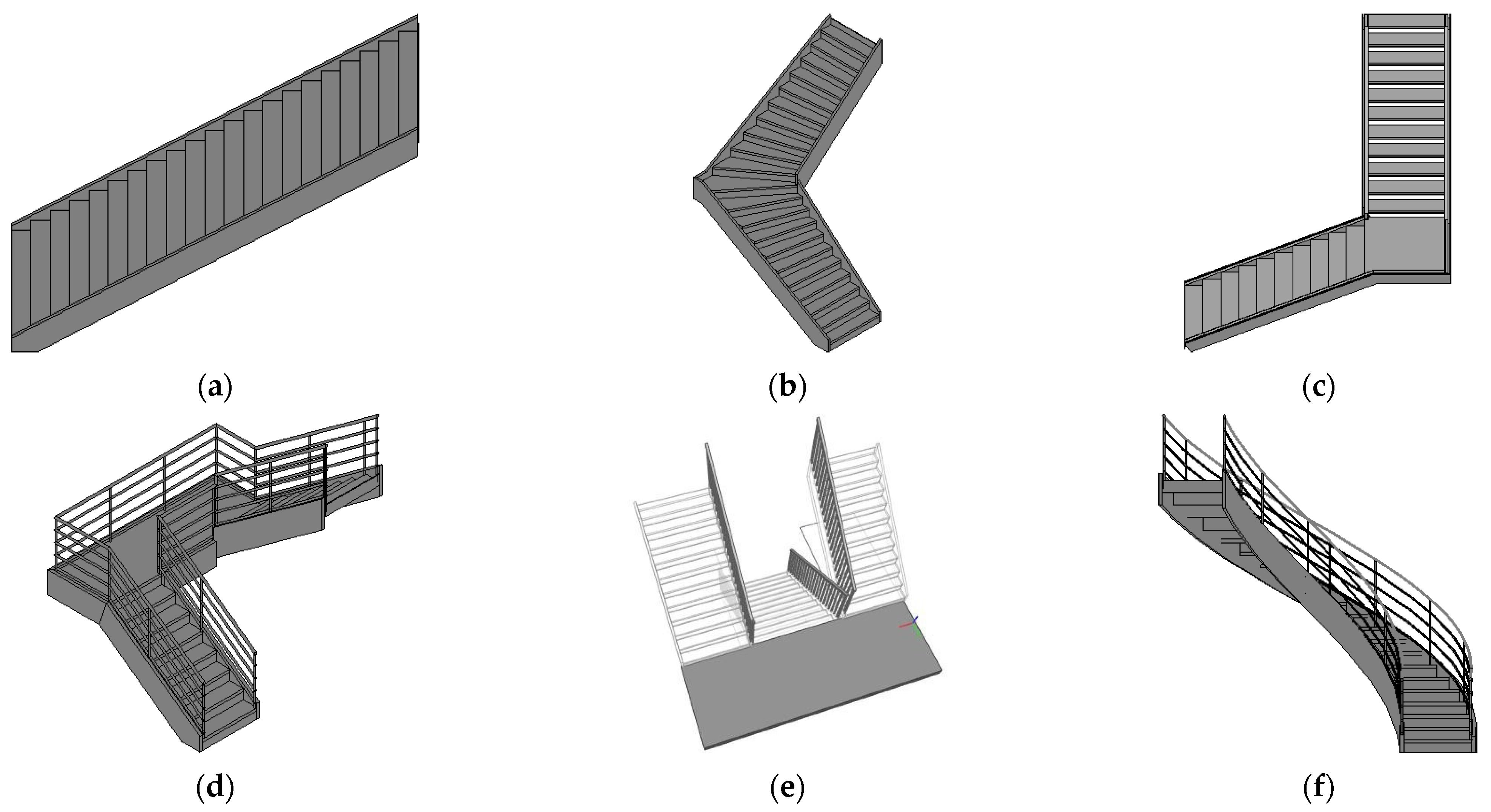
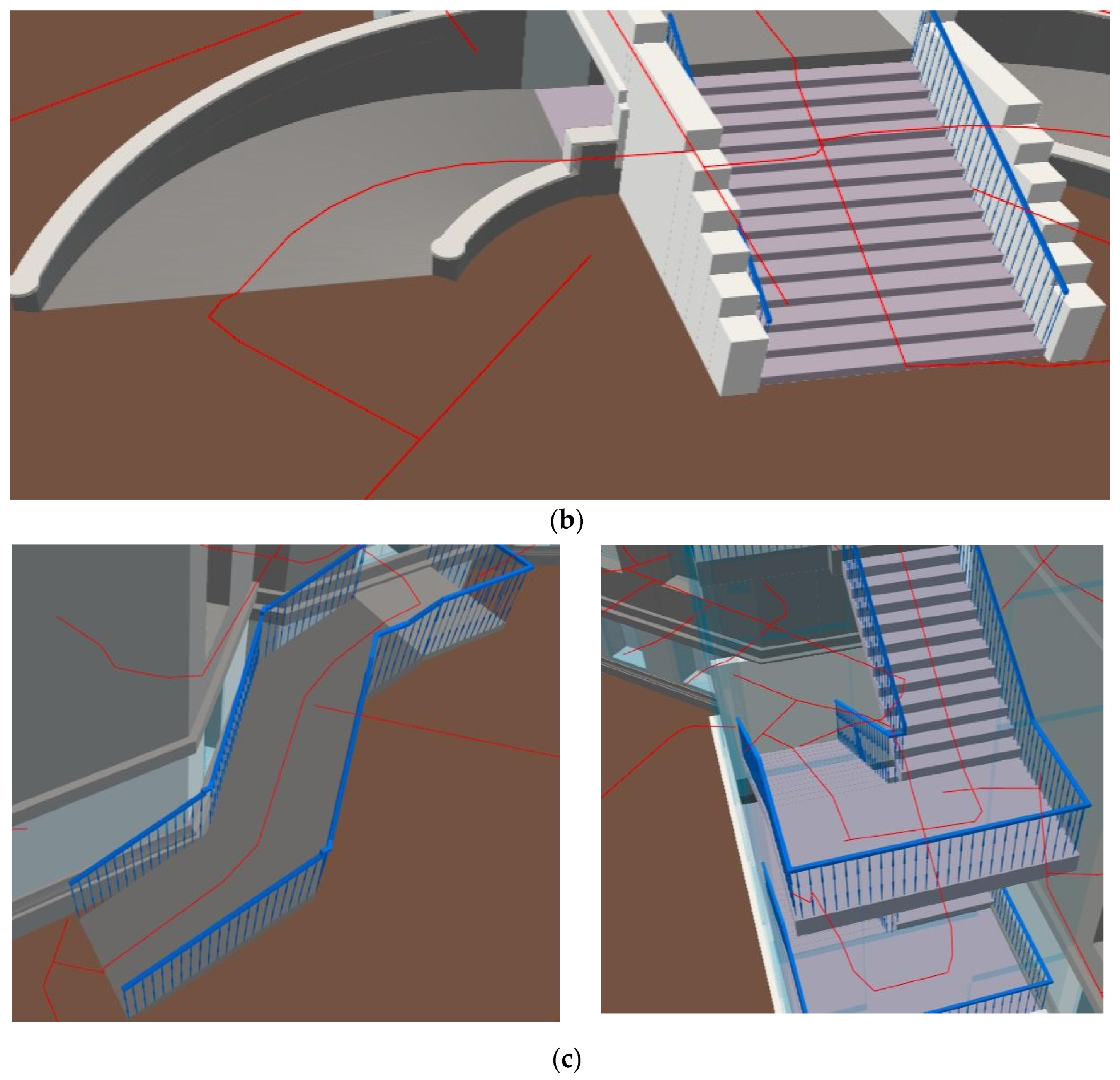
Stairs (IfcStair) and ramps (IfcRamp) are two primary cross-layer architectural components. We evaluated the performance of our proposed GINIT on stairs and ramps with both straight and curved shapes.

5.1.1. Stairs

The experiments were conducted on six different styles of staircase, namely, straight, turn, L-style, n-style, m-style, and winding staircases. These six styles are representative of most of the staircases found in BIM models. Using GINIT, we generated 3D topological maps for these staircases, as shown in Figure 8. Figure 9 depicts the 3D topological map generation for the straight staircase. Figure 9a,b show the 3D shapes and top-down projection image of the straight staircase, respectively, obtained from the design tools. Figure 9c,d show the binary image and 2D thinned topological map generated via the projection thinning process. The 2D thinned topological map is a straight line that accurately represents the accessible route of the top-down projection image. By intersecting the 2D thinned topological map with the 3D shapes, the final 3D topological map is obtained. Figure 9e presents an example of the 3D topological map of the straight staircase, which is straight and runs through the center face of the staircase.
Figure 10 is procession of abstracting the 3D map from a turn stair. Figure 10a shows the original 3D shapes of the turn staircase from the design tools. Figure 10b,c show the top-down projection image and the binary image. Different from the straight staircase, the turn staircase has a turn with an arbitrary degree in the middle of the staircase. Figure 10d,e present the thinned 2D topological map generated using the thinning algorithm and the final 3D topological map in the BIM model. Intuitively, the 2D topological map can capture the shape of the top-down projection image and the 3D topological map looks reasonable.
The L-style staircase differs from the turn staircase in that it includes a transit platform, which is typically a slab represented by an IfcSlab instance. Moreover, the turn in the L-style stair is typically a right angle of 90°. An IfcStair instance in the L-style staircase typically comprises two IfcStairFlight instances and one IfcSlab instance, which connects the two flights. Figure 11 demonstrates the process of generating a 3D topological map from an L-style stair. Figure 11a is an L-style stair, whose top-down projection image captured from the design tool is shown in Figure 11b. Figure 11c,d are the binary image and the 2D topological map generated via the projection thinning process. Figure 11e is the final 3D topological map in a concrete house model. The 2D topological map is consistent with the top-down projection image, and the 3D topological map is able to propose a rational route.
The n-style staircase is a collective type of staircase found in real-world buildings, occupying less internal space compared to L-style and turn stairs. It features a 180° turn through a transit platform, which is defined by a slab. Like the L-style staircase, the n-style staircase is typically composed of two IfcStairFlight instances and one IfcSlab instance. Figure 12 showcases the 3D topological map generated from an n-style stair. In Figure 12a, we can see a typical n-style staircase, along with its top-down projection image in Figure 12b. The top-down projection of the n-style staircase resembles the letter ‘n’, and the width of the two IfcStairFlight instances can be adjusted using a design tool. As depicted in Figure 12c,d, both the binary image and 2D topological map also resemble the letter ‘n’. Figure 12e showcases a 3D topological map of an actual n-style staircase, generated using our presented GINIT approach. The route provided by GINIT is reasonable and accurate.
m-style stairs are usually designed for use in crowded buildings, e.g., school buildings, because they provide more walking space. As shown in Figure 13a, the top half of the m-style staircase has two staircase flights, evacuating half of the individuals on a floor. Compared with L-style stairs or turn stairs, the stair flight in the bottom half of the stair is usually wider. Figure 13b–d are the top-down projection image, the binary image, and the generated 2D topological map, all of which look like the character ‘m’. In the m-style staircase, the staircase flights in the top half and bottom half of the stair are not overlapped to avoid head knocking. To save inner space, the space between the stair flights in the top half and the bottom half are limited. The limited space between the stair flights in the top half and bottom half of the m-style stair is depicted in Figure 13b,c. In Figure 13e, a real-world m-style staircase in a building is shown, along with its 3D topological map generated by GINIT, which is also able to provide a reasonable representation of the stair.
The winding stair is the last type of stair to be evaluated in this study. Compared with previously discussed stairs, the stair flight in a winding stair is not straight. These irregular shapes of the winding stair cause failure in topological map generation using some existing schemes. Figure 14 demonstrates the production of a 3D topological map of a winding staircase. Figure 14a,b are the 3D shapes and the top-down projection image obtained using the design tool. Figure 14c,d are the binary image and its corresponding thinned topological map. Although the 2D topological map is not the exact centerline of the top-down projection image, it is also possible to construct a 3D topological map. The 3D topological map of a winding staircase is presented in Figure 14e. It can be observed that the topological map appears rational after the sampling of points in the 2D topological map during the intersection process between the projection and BIM.

5.1.2. Ramps

Figure 15 shows the 3D shapes of a straight ramp and a curved ramp. In IFC specification, the 3D shapes of a straight ramp can be represented by a solid extrusion model (Figure 15a), while a curved ramp is usually modeled by triangular meshes (Figure 15b).
Figure 16 illustrates the 3D topological map generation of a straight ramp. Figure 16a,b display the 3D shapes and the top-down projection image of the straight ramp obtained from the design tool. Figure 16c,d represent the binary image and the 2D thinned topological map generated via projection thinning. The 2D thinned topological map is a straight line that accurately describes the accessible route of the top-down projection image. Upon intersection with the 3D shapes, the final 3D topological map is achieved. Figure 16e depicts a concrete example of the 3D topological map of the straight ramp, which appears at the center surface.
Figure 17a presents a typical curved ramp with a top-down projection image in Figure 17b. The design tool permits adjusting the curves of the curved ramp to obtain different types. Figure 17c,d exhibit the binary image and the 2D topological map obtained via the projection thinning process. Figure 17e displays the final 3D topological map of a concrete curved ramp. In the areas near both ends of the ramp, the 2D topological map is not the exact centerline of the top-down projection image. However, the projection–BIM intersection process’ point sampling addresses this problem and outputs a rational 3D topological map.
The accuracies of the topological maps were evaluated in all the six types of staircase and two types of ramp. In the X-Z plane, the lengths of the generated shortest paths are the lengths of the generated 2D topological maps. The length of the generated shortest path of a cross-layer architectural component in a 3D environment is the length of its 3D topological map. The actual shortest lengths in 3D and 2D environments are the lengths of the middle lines of cross-layer architectural components and their corresponding top-down projection images, respectively.
Table 1 presents the accuracies of eight types, where the accuracies in the 2D topological maps exceed 90%, and those in the 3D topological maps are no less than 95%. This suggests that point selection in the projection–BIM intersection process not only reduces computation complexity, but also improves the accuracy of topological maps. Architectural components with more regular 3D forms tend to achieve higher accuracy. For instance, both the straight staircase and straight ramp attain 100% accuracy. In contrast, the L-, n-, and m-style stairs, which are more complex than the straight ones, have accuracies in both the 2D and 3D topological maps of more than 97% and less than 100%. Notably, since the L-style and turn stairs possess similar 3D shapes, they exhibit equivalent accuracies. Winding stairs and curved ramps have the most complex 3D shapes, resulting in the lowest accuracy of all eight cross-layer architectural components. However, their accuracies in the 2D topological maps are both higher than 90%, and their accuracies in the 3D topological maps are higher than 95%. Overall, these results demonstrate that our presented GINIT can effectively generate accurate topological maps for cross-layer architectural components.

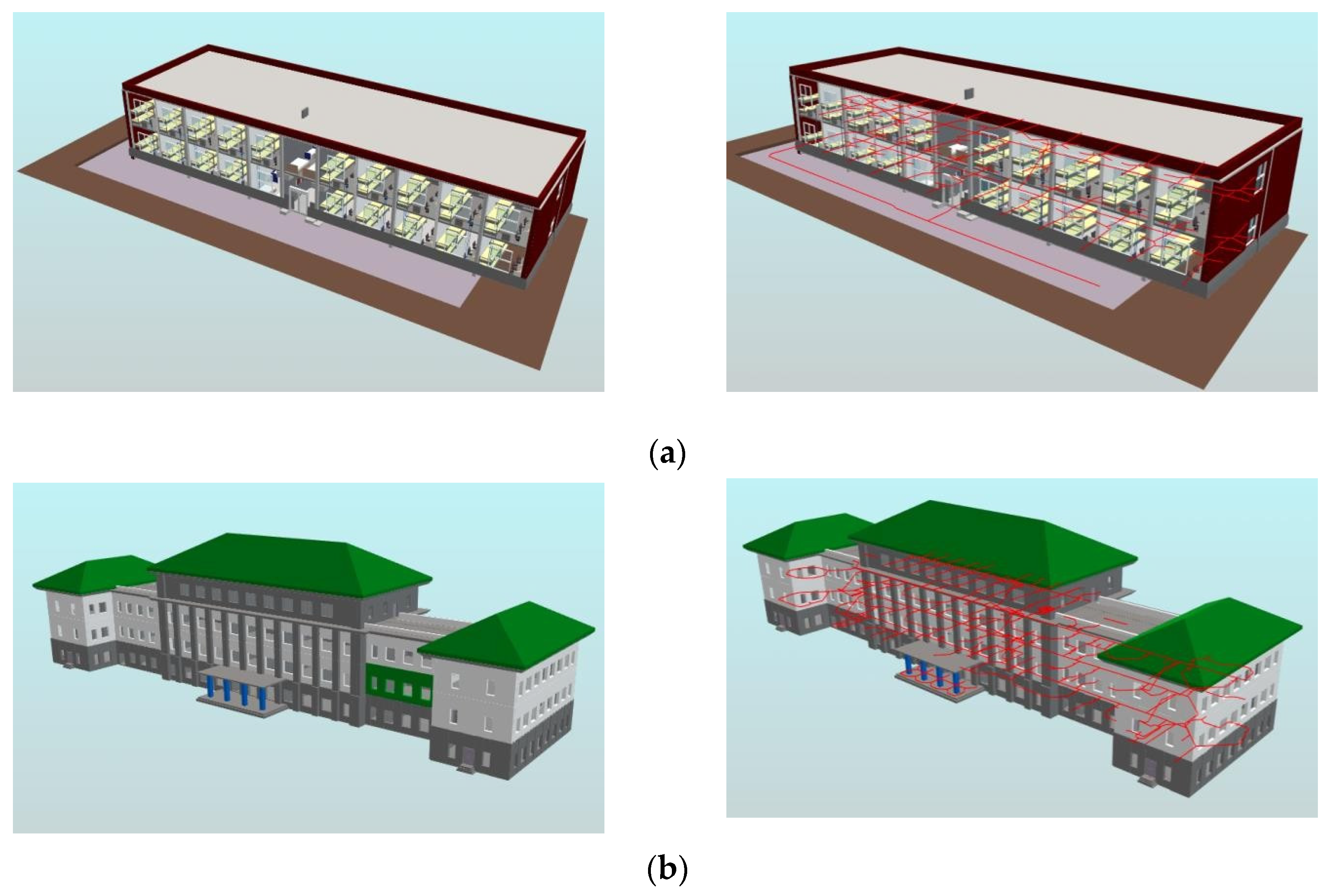
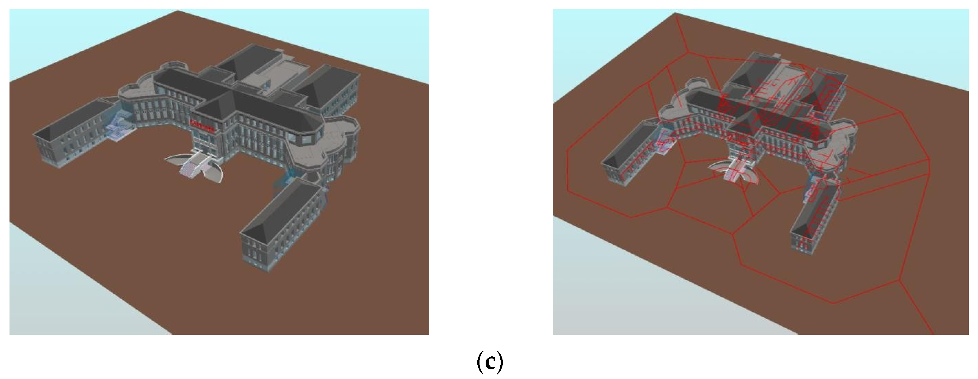
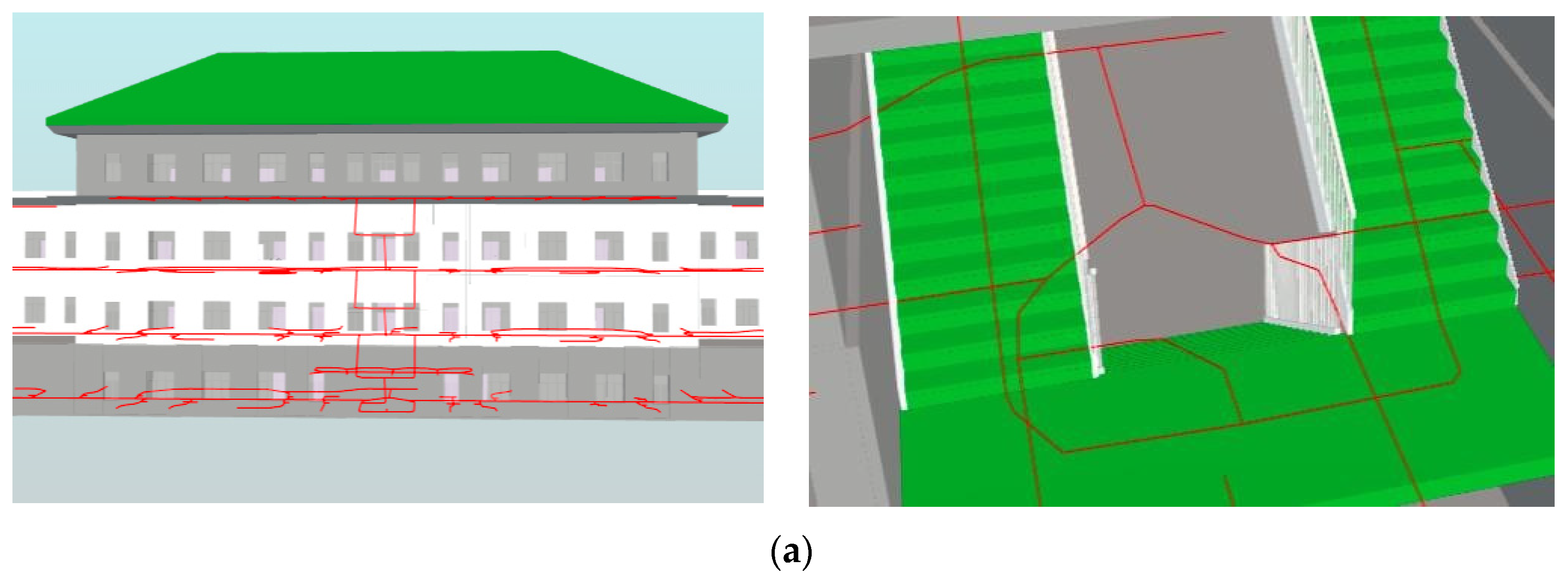
5.2. Multi-Floor BIM Model Evaluation

This subsection first illustrated the adaptability of GINIT to extract floor-level navigation networks. Figure 18a exhibits a floor-level indoor map of an opening office. Many schemes that depend on the indoor spaces, e.g., rooms, perform poorly in this BIM model, because the opening office has only a few small rooms, but a lot of furniture. Figure 18b shows the floor-level indoor navigation networks of an underground parking lot. A large portion of the inner space comprises parking spaces, which are defined by some IfcProxy instances but not IfcSpace instances. Similar to the opening office, the current topological map generation algorithms can hardly identify the navigation network in most areas. However, our proposed GINIT provides a satisfactory navigation network, which can reach every corner of the parking lot. Subsequently, our GINIT is applied to more scenarios than the current navigation network production algorithms.
We conducted a test of the effectiveness of the 3D indoor routes produced by GINIT on three selected buildings. Table 2 presents some statistics of these buildings. The dormitory is a two-floor building designed for student housing, featuring one straight stair and one n-style stair, comprising a total of three staircase flights. The school building, on the other hand, is a four-floor building with three m-style staircases and four n-style staircases, which includes offices, meeting rooms, and various laboratories. The Peking University People’s Hospital, established in 1918, has a total floor area of 22,000 m2 and is the first general hospital financed and operated by Chinese nationals. It has four floors in the main building and three floors in each of the four wing buildings, with 5 ramps and 29 stair flights for wheelchair and car users. In the experiments, the selected 3D building models contain precise geometric information about the building components, which can be utilized to determine accurate weight assignments for cross-floor links. In Figure 19, the left-side images show the 3D models of the buildings, while the right-side images depict the indoor networks generated by GINIT. Figure 20 displays some examples of non-level passages.
We also conducted experiments to evaluate the accuracy of the navigation networks in the three buildings. In cases where the two points of interest (POIs) were on the same floor, we computed the actual shortest path using the grid-based maps with the A-star algorithm [13]. However, if the two POIs were on different floors, the actual shortest route consisted of three parts: the route from one POI to a cross-layer architectural component, the route of the cross-layer component, and the path from the cross-floor component to the other POI. The length of the actual shortest route was also computed using the grid-based map and A-star algorithm [13]. Interestingly, the length of the actual shortest path was always shorter than the length of the generated topological path. To demonstrate the accuracy of the navigation networks generated by GINIT, we selected five representative pairs of POIs from numerous experiments.
Table 3 displays the results of the experiments, including the length of the generated shortest route, the length of the real shortest route, and the precision of the trial outcome. The accuracies were all higher than 81%, with the highest precision of 96.11% achieved for the two POIs from the entrance to a hallway in the school’s architecture. Notably, the accuracies of the two POIs from the entrance to a hallway were the highest among all scenarios, possibly because the accessible grids from the entrance to a hallway are usually more regular than in other scenarios. On the other hand, the cross-floor POIs had the lowest accuracies in all three architectures, likely due to errors inherited from the cross-floor architectural components. Nevertheless, the accuracies were all higher than 81%. The average accuracies of the three architectures were 88.17%, 86.64%, and 86.05%, respectively, all of which were higher than 86%. These results suggest that the image thinning technique can obtain accurate navigation networks from grid-based maps.

6. Conclusions

Indoor mapping is critical for facilitating intelligent indoor tasks from various perspectives. We present an auto-generation scheme for 3D indoor navigation networks from BIM data using image thinning, which we term GINIT. The 3D indoor maps consist of cross-level navigation networks and cross-floor paths. Our proposed method involves the extraction of both geometric and semantic data from BIM data to generate floor-level grid-based maps. We then extract the floor-level navigation networks through image thinning applied to the grid-based maps. The cross-floor topological maps are generated through a three-step process involving top-down projection, projection thinning, and the projection–BIM intersection. The top-down projection maps 3D shapes of a cross-layer architectural component into a 2D image, which is then processed through image thinning to obtain a 2D topological map. The projection–BIM intersection restores the cross-layer 3D topological map by intersecting the 2D topological map with the 3D forms from BIM data. Finally, we conduct experiments on eight types of cross-layer architectural component and three real-world multi-floor buildings to evaluate the performance of our presented GINIT. The experimental results demonstrate that GINIT can generate accurate 3D indoor navigation networks from BIM data.
The innovation of this study is that an automatic 3D indoor navigation network generation scheme is proposed with the integration of BIM and image thinning techniques. The current BIM-based navigation network generation schemes are mainly based on the theory of geometry in computer graphics. Unlike these, the proposed GINIT purely uses image thinning, which belongs to imaging theory, another branch of computer graphics. From the perspective of floor-level indoor maps, navigation networks are directly obtained using thinning grid-based maps. Thus, GINIT can generate navigation networks from any indoor environment, keeping the human cognition of paths. Additionally, GINIT requires no knowledge of space definitions. From the aspect of cross-floor indoor maps, the proposed GINIT can be applied to obtain 3D cross-floor paths from architectural components with arbitrary 3D forms. Because image thinning can be applied to obtain the skeletons of any binary image, the proposed GINIT is a powerful method of automatically generating indoor maps from BIM, and is available at building.rickricks.com (accessed on 2 June 2023). It is also expected that this study inspires more innovative studies on BIM from the perspective of imaging theory, and that this study advances the adoption of BIM in AECO/FM industry from the view of indoor maps [41].

Author Contributions

Methodology, Xiaoping Zhou; writing—original draft preparation, Weisong Zhang and Yukang Wang; writing—review and editing, Xiaoping Zhou, Weisong Zhang and Yukang Wang. All authors have read and agreed to the published version of the manuscript.

Funding

This work was supported by the Key Research and Development Program of Anhui Province of China under grant no. 202104a07020017.

Data Availability Statement

Not applicable.

Conflicts of Interest

The authors declare no conflict of interest.

References

  1. Zhou, X.; Li, H.; Wang, J.; Zhao, J.; Xie, Q.; Li, L.; Liu, J.; Yu, J. CloudFAS: Cloud-based building fire alarm system using Building Information Modelling. J. Build. Eng. 2022, 53, 104571. [Google Scholar] [CrossRef]
  2. Zhou, X.; Xie, Q.; Guo, M.; Zhao, J.; Wang, J. Accurate and efficient indoor wayfinding based on building information modeling data. IEEE Trans. Ind. Inform. 2020, 16, 7459–7468. [Google Scholar] [CrossRef]
  3. Chen, A.Y.; Huang, T. Toward BIM-enabled decision making for in-building response missions. IEEE Trans. Intell. Transp. Syst. 2015, 16, 2765–2773. [Google Scholar] [CrossRef]
  4. Pang, Y.; Zhou, L.; Lin, B.; Lv, G.; Zhang, C. Generation of navigation networks for corridor spaces based on indoor visibility map. Int. J. Geogr. Inf. Sci. 2020, 34, 177–201. [Google Scholar] [CrossRef]
  5. Teo, T.-A.; Cho, K.-H. BIM-oriented indoor network model for indoor and outdoor combined route planning. Adv. Eng. Inform. 2016, 30, 268–282. [Google Scholar] [CrossRef]
  6. Fernández-Caramés, C.; Serrano, F.J.; Moreno, V.; Curto, B.; Rodríguez-Aragón, J.F.; Alves, R. A real-time indoor localization approach integrated with a Geographic Information System (GIS). Robot. Auton. Syst. 2016, 75, 475–489. [Google Scholar] [CrossRef]
  7. Zhou, X.; Sun, K.; Wang, J.; Zhao, J.; Feng, C.; Yang, Y.; Zhou, W. Computer Vision Enabled Building Digital Twin Using Building Information Model. IEEE Trans. Ind. Inform. 2022, 19, 2684–2692. [Google Scholar] [CrossRef]
  8. Lin, Y.-H.; Liu, Y.-S.; Gao, G.; Han, X.-G.; Lai, C.-Y.; Gu, M. The IFC-based path planning for 3D indoor spaces. Adv. Eng. Inform. 2013, 27, 189–205. [Google Scholar] [CrossRef] [Green Version]
  9. Lin, W.Y.; Lin, P.H. Intelligent generation of indoor topology (i-GIT) for human indoor wayfinding based on IFC models and 3D GIS technology. Autom. Constr. 2018, 94, 340–359. [Google Scholar] [CrossRef]
  10. Taneja, S.; Akinci, B.; Garrett, J.H., Jr.; Soibelman, L. Algorithms for automated generation of navigation models from building information models to support indoor map-matching. Autom. Constr. 2016, 61, 24–41. [Google Scholar] [CrossRef] [Green Version]
  11. Chen, A.Y.; Chu, J.C. TDVRP and BIM integrated approach for in-building emergency rescue routing. J. Comput. Civ. Eng. 2016, 30, C4015003. [Google Scholar] [CrossRef]
  12. Cheng, J.C.; Chen, K.; Wong, P.K.-Y.; Chen, W.; Li, C.T. Graph-based network generation and CCTV processing techniques for fire evacuation. Build. Res. Inf. 2021, 49, 179–196. [Google Scholar] [CrossRef]
  13. Candra, A.; Budiman, M.A.; Hartanto, K. Dijkstra’s and a-star in finding the shortest path: A tutorial. In Proceedings of the 2020 International Conference on Data Science, Artificial Intelligence, and Business Analytics (DATABIA), Medan, Indonesia, 6–17 July 2020; pp. 28–32. [Google Scholar]
  14. Yang, L.; Worboys, M. Generation of navigation graphs for indoor space. Int. J. Geogr. Inf. Sci. 2015, 29, 1737–1756. [Google Scholar] [CrossRef] [Green Version]
  15. Ma, Y.; Zheng, G.; Perruquetti, W. Cooperative path planning for mobile robots based on visibility graph. In Proceedings of the 32nd Chinese Control Conference, Xi’an, China, 26–28 July 2013; pp. 4915–4920. [Google Scholar]
  16. Haunert, J.-H.; Sester, M. Area collapse and road centerlines based on straight skeletons. GeoInformatica 2008, 12, 169–191. [Google Scholar] [CrossRef]
  17. Bruck, J.; Gao, J.; Jiang, A. MAP: Medial axis based geometric routing in sensor networks. In Proceedings of the 11th Annual International Conference on Mobile Computing and Networking, San Diego, CA, USA, 17–21 July 2005; pp. 88–102. [Google Scholar] [CrossRef]
  18. Lee, J. A spatial access-oriented implementation of a 3-D GIS topological data model for urban entities. GeoInformatica 2004, 8, 237–264. [Google Scholar] [CrossRef]
  19. Fu, M.; Liu, R.; Qi, B.; Issa, R.R. Generating straight skeleton-based navigation networks with Industry Foundation Classes for indoor way-finding. Autom. Constr. 2020, 112, 103057. [Google Scholar] [CrossRef]
  20. Lin, W.Y. Automatic generation of high-accuracy stair paths for straight, spiral, and winder stairs using IFC-based models. ISPRS Int. J. Geo-Inf. 2020, 9, 215. [Google Scholar] [CrossRef] [Green Version]
  21. Lam, L.; Lee, S.-W.; Suen, C.Y. Thinning methodologies-a comprehensive survey. IEEE Trans. Pattern Anal. Mach. Intell. 1992, 14, 869–885. [Google Scholar] [CrossRef] [Green Version]
  22. Sudarma, M.; Sutramiani, N.P. The thinning Zhang-Suen application method in the image of Balinese scripts on the papyrus. Int. J. Comput. Appl. 2014, 91, 9–13. [Google Scholar] [CrossRef]
  23. BuildingSMART, Industry Foundation Classes IFC2x Edition 3 Technical Corrigendum 1. Available online: http://www.buildingsmart-tech.org/ifc/IFC2x3/TC1.html (accessed on 4 April 2023).
  24. Afyouni, I.; Ray, C.; Claramunt, C. Spatial models for context-aware indoor navigation systems: A survey. J. Spat. Inf. Sci. 2012, 4, 85–123. [Google Scholar] [CrossRef] [Green Version]
  25. Chen, Q.; Liu, G.; Ma, X.; Mariethoz, G.; He, Z.; Tian, Y.; Weng, Z. Local curvature entropy-based 3D terrain representation using a comprehensive Quadtree. ISPRS J. Photogramm. Remote Sens. 2018, 139, 30–45. [Google Scholar] [CrossRef]
  26. Oğuz, O.; Durupınar, F.; Güdükbay, U. Dynamic point-region quadtrees for particle simulations. Inf. Sci. 2013, 218, 133–145. [Google Scholar] [CrossRef] [Green Version]
  27. Eppstein, D.; Goodrich, M.T.; Sun, J.Z. The skip quadtree: A simple dynamic data structure for multidimensional data. In Proceedings of the Twenty-First Annual Symposium on Computational Geometry, Pisa, Italy, 6–8 June 2005; pp. 296–305. [Google Scholar] [CrossRef]
  28. Remolina, E.; Kuipers, B. Towards a general theory of topological maps. Artif. Intell. 2004, 152, 47–104. [Google Scholar] [CrossRef] [Green Version]
  29. Wallgrün, J.O. Autonomous construction of hierarchical voronoi-based route graph representations. In Proceedings of the Spatial Cognition IV. Reasoning, Action, Interaction: International Conference Spatial Cognition 2004, Frauenchiemsee, Germany, 11–13 October 2004; pp. 413–433. [Google Scholar] [CrossRef]
  30. Kneidl, A.; Borrmann, A.; Hartmann, D. Generation and use of sparse navigation graphs for microscopic pedestrian simulation models. Adv. Eng. Inform. 2012, 26, 669–680. [Google Scholar] [CrossRef]
  31. Boissonnat, J.-D.; Dyer, R.; Ghosh, A. Delaunay triangulation of manifolds. Found. Comput. Math. 2018, 18, 399–431. [Google Scholar] [CrossRef]
  32. Mortari, F.; Zlatanova, S.; Liu, L.; Clementini, E. “Improved geometric network model” (ignm): A novel approach for deriving connectivity graphs for indoor navigation. ISPRS Ann. Photogramm. Remote Sens. Spat. Inf. Sci. 2014, 2, 45. [Google Scholar] [CrossRef] [Green Version]
  33. Xiong, Q.; Zhu, Q.; Du, Z.; Zhu, X.; Zhang, Y.; Niu, L.; Li, Y.; Zhou, Y. A dynamic indoor field model for emergency evacuation simulation. ISPRS Int. J. Geo-Inf. 2017, 6, 104. [Google Scholar] [CrossRef]
  34. Tsiliakou, E.; Dimopoulou, E. 3D Network Analysis for Indoor Space Applications. Int. Arch. Photogramm. Remote Sens. Spat. Inf. Sci. 2016, XLII-2/W2, 147–154. [Google Scholar] [CrossRef] [Green Version]
  35. Li, K.-J.; Conti, G.; Konstantinidis, E.; Zlatanova, S.; Bamidis, P. OGC IndoorGML: A standard approach for indoor maps. In Geographical and Fingerprinting Data to Create Systems for Indoor Positioning and Indoor/Outdoor Navigation; Elsevier: Amsterdam, The Netherlands, 2019; pp. 187–207. [Google Scholar] [CrossRef]
  36. Saeed, K.; Tabędzki, M.; Rybnik, M.; Adamski, M. K3M: A universal algorithm for image skeletonization and a review of thinning techniques. Int. J. Appl. Math. Comput. Sci. 2010, 20, 317–335. [Google Scholar] [CrossRef]
  37. Abeysinghe, S.; Ju, T.; Baker, M.L.; Chiu, W. Shape modeling and matching in identifying 3D protein structures. Comput. Aided Des. 2008, 40, 708–720. [Google Scholar] [CrossRef]
  38. Bucksch, A. A practical introduction to skeletons for the plant sciences. Appl. Plant Sci. 2014, 2, 1400005. [Google Scholar] [CrossRef] [PubMed]
  39. Groher, M.; Zikic, D.; Navab, N. Deformable 2D-3D registration of vascular structures in a one view scenario. IEEE Trans. Med. Imaging 2009, 28, 847–860. [Google Scholar] [CrossRef] [PubMed]
  40. Xie, X.; Lu, H.; Pedersen, T.B. Efficient distance-aware query evaluation on indoor moving objects. In Proceedings of the 2013 IEEE 29th International Conference on Data Engineering (ICDE), Brisbane, Australia, 8–12 April 2013; pp. 434–445. [Google Scholar] [CrossRef] [Green Version]
  41. Hartmann, T.; Trappey, A. Advanced Engineering Informatics-Philosophical and methodological foundations with examples from civil and construction engineering. Dev. Built Environ. 2020, 4, 100020. [Google Scholar] [CrossRef]
Figure 1. Number of pixels.
Ijgi 12 00231 g001
Figure 2. Floor-level navigation network generation using image thinning: (a) grid-based and thinning map; (b) the navigation network.
Ijgi 12 00231 g002
Figure 3. The three-step process of topological map generation of a cross-floor element.
Ijgi 12 00231 g003
Figure 4. Coordinate settings in the BIM environment.
Ijgi 12 00231 g004
Figure 5. Primary elements of a cross-floor element, e.g., stair (IfcStair).
Ijgi 12 00231 g005
Figure 6. Two approaches to binary filling. The inner points are filled with black, while the outer points are filled with white: (a) Y extension; (b) X-Z radiation.
Ijgi 12 00231 g006
Figure 7. Projection thinning, from a binary image to a 2D topological map: (a) binary image; (b) 2D topological map.
Ijgi 12 00231 g007
Figure 8. Evaluated staircases: (a) straight staircase; (b) turn staircase; (c) L-style staircase; (d) n-style staircase; (e) m-style staircase; (f) winding staircase.
Ijgi 12 00231 g008
Figure 9. Three-dimensional indoor map of a straight stair: (a) 3D shapes; (b) top-down projection; (c) binary image; (d) 2D thinned topological map; (e) 3D topological map.
Ijgi 12 00231 g009aIjgi 12 00231 g009b
Figure 10. Three-dimensional indoor map of a turn stair: (a) 3D shapes; (b) top-down projection; (c) binary image; (d) 2D thinned topological map; (e) 3D topological map.
Ijgi 12 00231 g010
Figure 11. Three-dimensional indoor map of the L-style stair: (a) 3D shapes; (b) top-down projection; (c) binary image; (d) 2D thinned topological map; (e) 3D topological map.
Ijgi 12 00231 g011
Figure 12. Three-dimensional indoor map of the n-style stair: (a) 3D shapes; (b) top-down projection; (c) binary image; (d) 2D thinned topological map; (e) 3D topological map.
Ijgi 12 00231 g012aIjgi 12 00231 g012b
Figure 13. The generation of a 3D indoor map from an m-style stair: (a) 3D shapes; (b) top-down projection; (c) binary image; (d) 2D thinned topological map; (e) 3D topological map.
Ijgi 12 00231 g013
Figure 14. Three-dimensional indoor map of a winding stair: (a) 3D shapes; (b) top-down projection; (c) binary image; (d) 2D thinned topological map; (e) 3D topological map.
Ijgi 12 00231 g014
Figure 15. Evaluated ramps: (a) straight ramp; (b) curved ramp.
Ijgi 12 00231 g015
Figure 16. Three-dimensional indoor map of a straight ramp: (a) 3D shapes; (b) top-down projection; (c) binary image; (d) 2D thinned topological map; (e) 3D topological map.
Ijgi 12 00231 g016
Figure 17. Three-dimensional indoor map of a curved ramp: (a) 3D shapes; (b) top-down projection; (c) binary image; (d) 2D thinned topological map; (e) 3D topological map.
Ijgi 12 00231 g017
Figure 18. Floor-level indoor map: (a) opening office; (b) underground parking lot.
Ijgi 12 00231 g018
Figure 19. Test of BIM and indoor paths generated by GINIT: (a) two-floor dormitory; (b) four-floor school building—research; (c) Peking University People’s Hospital.
Ijgi 12 00231 g019aIjgi 12 00231 g019b
Figure 20. Examples of non-level passages and paths produced by GINIT selected from testing buildings: (a) m-style stairs in the school building; (b) curved ramps for cars and a straight stair before the front door of the hospital building; (c) curved ramp for wheelchairs and n-style stairs for users in the hospital building.
Ijgi 12 00231 g020aIjgi 12 00231 g020b
Table 1. Accuracy of the cross-layer route production.
TypeNameAccuracy of 2D Topological MapAccuracy of 3D Topological Map
Generated Length (cm)Actual Length (cm)Accuracy (%)Generated Length (cm)Actual Length (cm)Accuracy (%)
StairStraight526.19526.19100603.29660.96100
Turn538.58560.5796.35623.33688.6797.56
L-style597.65603.2999.101112.54723.8498.94
n-style621.89623.3399.77421.61738.1999.84
m-style1089.201112.5497.901362.031324.0497.13
Winding463.20421.6190.14538.54515.2695.48
RampStraight1090.001090.001001161.081161.08100
Curved1279.991188.0492.261277.241261.3398.74
Table 2. Indoor layouts of the buildings selected for testing.
#NameUsageFloorsStair FlightsRamps Flights
1DormitoryLoading230
2School BuildingResearch4170
3Peking University People’s HospitalHospital4290
Table 3. Accuracy of topological maps in multi-floor real-world buildings.
Building# of Pairs of
POIs
Length of Generated Route (cm)Length of Real Route
(cm)
Precision of Two POIs (%)Accuracy
Dormitory11535.511463.2295.0688.17
22204.181995.3789.54
33706.553422.5891.70
42602.492203.9581.92
54637.293951.6682.65
School
Building
12941.002830.7896.1186.64
21769.621497.7981.85
34109.663801.8591.90
42773.752341.1481.52
54044.273422.3381.83
Hospital11503.881398.5492.47
21767.521493.7281.67
32689.312304.5983.3186.05
43598.443049.7682.01
54503.894123.2690.77
Disclaimer/Publisher’s Note: The statements, opinions and data contained in all publications are solely those of the individual author(s) and contributor(s) and not of MDPI and/or the editor(s). MDPI and/or the editor(s) disclaim responsibility for any injury to people or property resulting from any ideas, methods, instructions or products referred to in the content.

