1. Introduction
From the robotization of conventional flexible endoscopes to the upgrading of various minimally invasive surgical instruments, continuum robots have been used more and more extensively in the medical field in recent years [
1]. Their narrow curvilinear shape allows them to pass through bodily lumens, natural orifices, or small surgical incisions, and the tendon-driven mechanism that can control the bending of the tip allows for more flexible adjustments of the device, either for imaging or surgical tasks. Although intelligence and automation have always been the ultimate goals of such robots, master–slave control is still an important human–robot interaction method for such robots today, considering the complexity, safety, and ethical requirements of the clinical processes involved. Since this class of robots has many specific application needs, some related works have focused on a master device to make them more suitable for the needs of robot control and clinical procedure management.
The most basic function of the relevant master control devices is to provide the operator with human–machine interaction inputs, such as the use of a parallel structure in the Flex robotic system to remotely translate the robot scope [
2], the serial-structure-based Geomagic Touch unit for the endoscopic submucosal dissection (ESD) [
3] and transoral robotic surgery (TORS) [
4], and a controller with two sticks for robotic-assisted bronchoscopy (RAB) [
5]. On the basis of providing inputs, the master control device is further empowered with haptic feedback to provide the operator with tactile information about the continuum robots’ interaction with the tissue. Of course, this relies first and foremost on the developed robot having its own force-sensing capabilities, e.g., the flexible ureteroscopy (fURS) robotic system [
6] and the vascular interventional surgical (VIS) robotic system [
7,
8].
More specifically, for the master device with haptic feedback, most of the existing flexible robotic systems are based on commercially available products, which provide three-degree-of-freedom (DOF) haptic feedback in position and six-DOF perception in position and attitude based on a tandem structure [
9,
10]. These haptic feedback devices have a relatively mature manufacturing process and control algorithm. Furthermore, the series–parallel connection-based mechanisms for six-DOF haptic feedback in position and attitude were developed [
11,
12]. However, the weight and volume of the actuators for haptic input in attitude were constrained, resulting in low export torque or high friction and inertia. To reduce the inertia, a six-DOF parallel mechanism was customized by placing all actuators on the base plane and coupling all DOFs [
13]. However, the abovementioned devices were primarily designed for virtual space collision feedback, and their application scene was objects moving in free space [
14]. While the most common operation mode used by doctors for the most flexible cable-driven continuum mechanisms [
15] is rotation and translation along one axis, the motion mode and operation mode of existing commercial tactile devices do not fully match the control requirements of continuum robots.
With the exception of the use of serial and parallel mechanisms, some haptic joysticks can realize torque reflection of the manipulator in multiple directions around a fixed point. This was normally based on the use of the gimbal structure and DC motor [
16], which can provide feedback for the two-DOF bending movement. In addition, a tendon-driven joystick was also manufactured to overcome the drawbacks of reduction gearboxes in precision and excess inertia [
17]. However, limited by the transmission structure, these joysticks can only achieve two-DOF bending haptic feedback. More recently, to overcome the difficulty of collision feeling emulation for rigid objects, actuators using magnetorheological (MR) fluids and electrorheological (ER) fluids were employed in haptic feedback joysticks [
18,
19]. The MR and ER fluid actuators provide faster response speeds and a better damping sense while being smaller in volume and simpler in structure [
20]. However, they can only produce resistance against the operators, which makes them limited when used individually. Therefore, to export force and regulate the position actively, motors were connected at the end of MR fluid actuators [
19,
21].
In this paper, we aim to propose a new haptic device design that allows for more efficient and intuitive control of the tip of the continuum robots intended for medical applications while at the same time allowing the operator not to keep their hands suspended, which can reduce hand tremors and fatigue. This is motivated by the challenges we have encountered in the practical manipulation of related robots, such as the continuum robots we developed for trans-esophageal echocardiography (TEE) and interventional catheterization [
22,
23]. To illustrate the basic feature of the design, we systematically present the analysis and experimental tests of the kinematic and static force models. To demonstrate its effectiveness in robot control and haptic feedback, we present a control architecture for master–slave interaction and rigorous experimental tests using an existing continuum-mechanism-based medical robot, i.e., a trans-esophageal ultrasound robot.
2. Design and Implementation
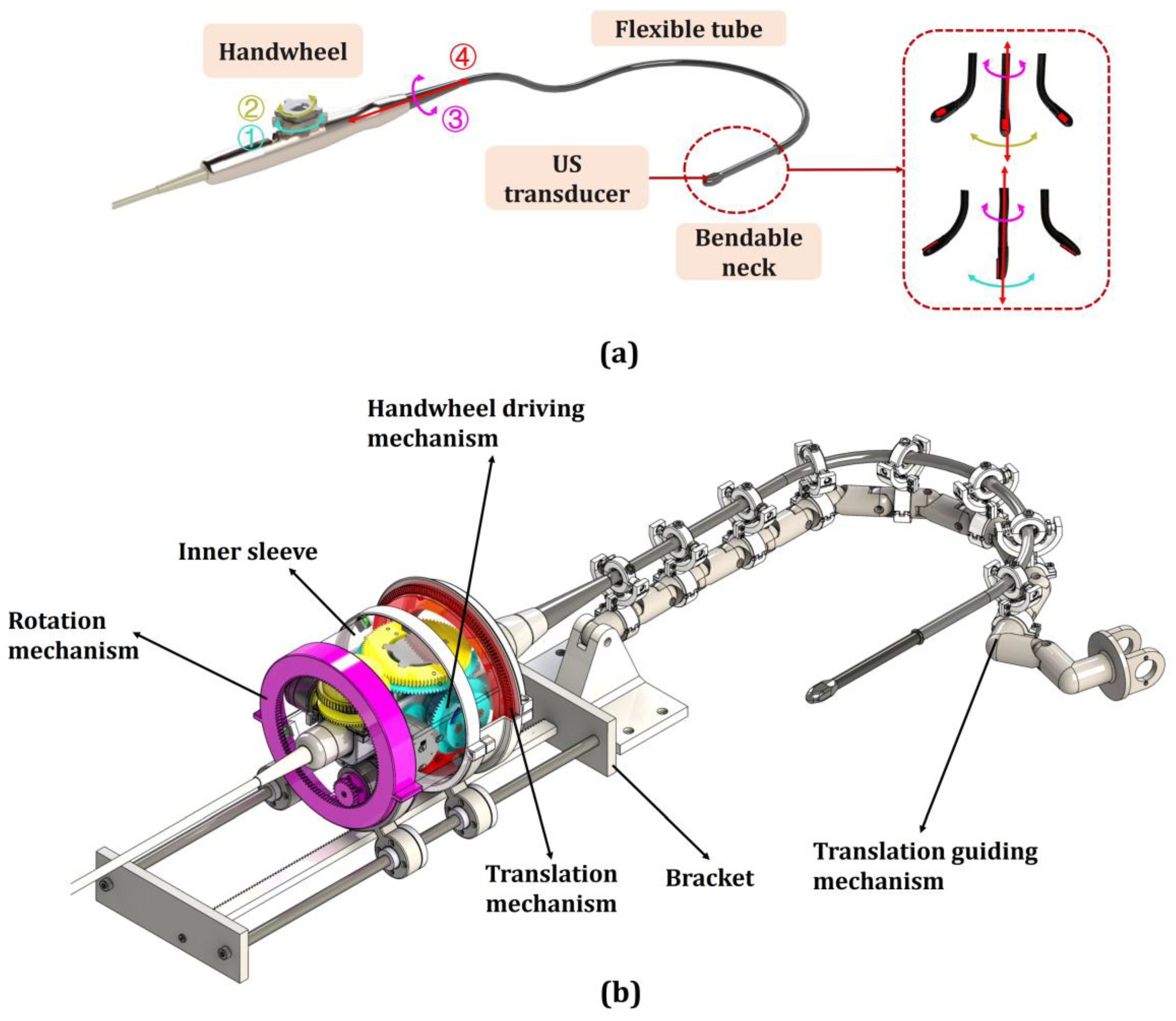
In this paper, a standard continuum-mechanism-based flexible robot for TEE was used to illustrate the operation process of the custom-made joystick. As shown in
Figure 1a, the commercial TEE probe (x7-2t, Philips, Amsterdam, The Netherlands) consists of an operating handle, flexible tube, bendable neck, and probe tip with an ultrasound (US) transducer. There are two coaxial handwheels on the operating handle to control the bending of the tip. The motion of the TEE probe can be expressed as follows:
where
,
,
, and
denote the handwheel angles for anteflex–retroflex bending and left–right bending of the probe tip, the rotation angle of the handle, and the translation of the handle along its long axis, as shown by the green, yellow, purple, and red arrows, respectively in
Figure 1a. The add-on robot in
Figure 1b has the ability to control four-DOF of the probe and detect the contact force at the probe tip by detecting the operation torque on the handwheel [
24].
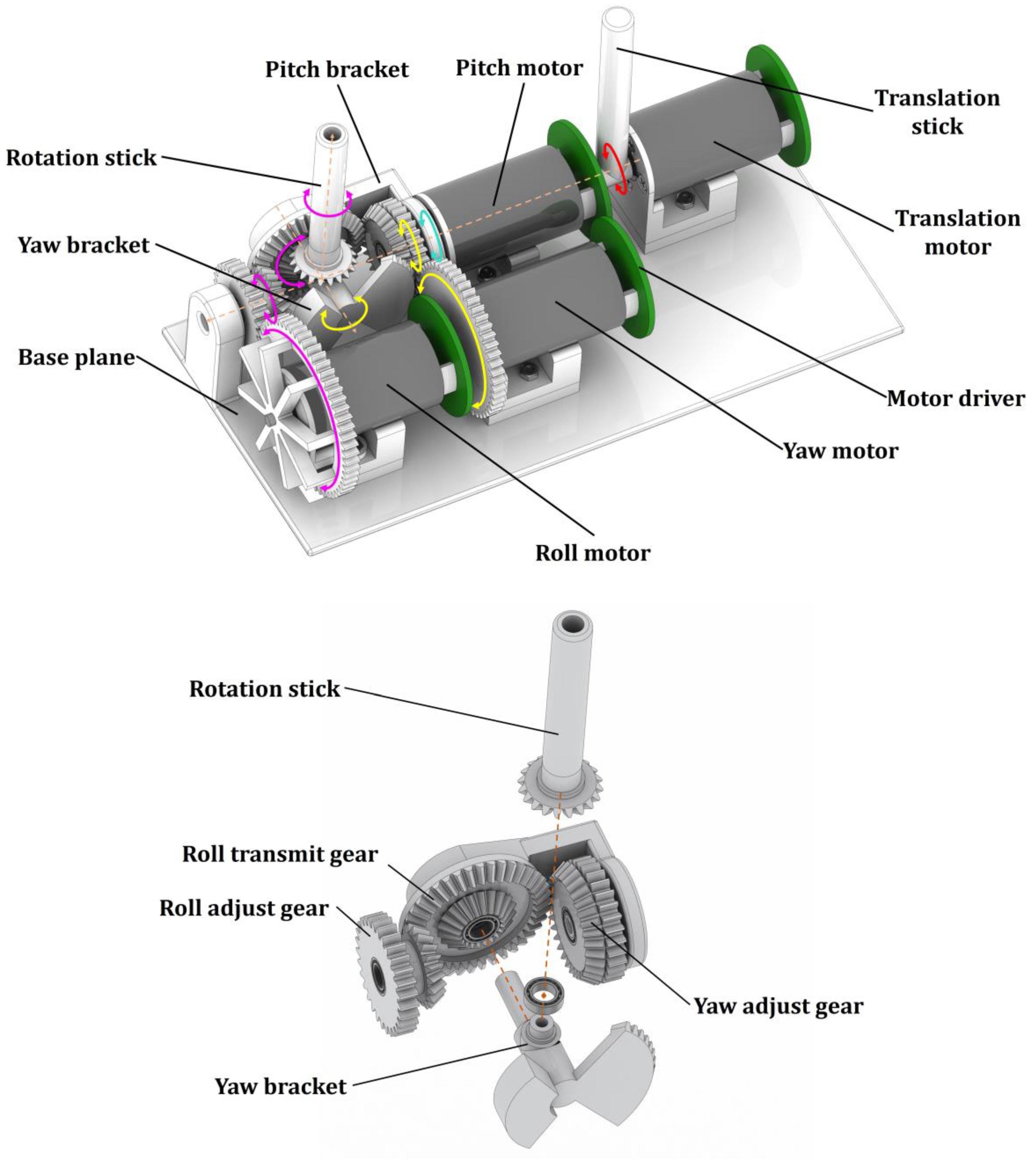
The CAD model of the proposed joystick is shown in
Figure 2. Corresponding to the motion of the TEE robot, the joystick has the capability of four-DOF motion perception and torque feedback. In the design, three of them are integrated onto the rotation stick for controlling the orientational adjustments of the TEE robot. The custom-made mechanism allows the orientational adjustments to occur around a fixed point of motion, which makes the adjustment intuitive and straightforward. Additionally, the translation stick is used to control the translational motion of the TEE robot. In the design, the two sticks are driven by four DC motors.
As shown in
Figure 2, the proposed mechanism mainly consists of two brackets and a series of drive gears with coupling relationships. The pitch bracket is fixed to the shaft of the pitch motor, and the yaw bracket is connected to the pitch bracket by the shaft and bearing. The rotation directions of the pitch bracket and the yaw bracket are perpendicular to each other. The drive from the pitch motor to the rotation stick is realized by the pitch bracket (shown by the green arrow), the drive from the yaw motor to the rotation stick is realized by a set of gears (shown by the yellow arrow), and the drive from the roll motor to the rotation stick is realized by another set of gears (shown by the purple arrow). When the pitch bracket is rotated, the yaw motor and roll motor will control the rotation of the corresponding angle to hold on to the yaw and roll postures of the stick. If the yaw bracket rotates on its own, the roll motor will also rotate synchronously to achieve motion decoupling.
The diameter of the motors is 28 mm and the length is 45 mm. The base plane is 210 mm in length and 100 mm in width. The shaft of the motors and the rotation center of the sticks are 30 mm above the base plane. Coordinating with the overall structure, the length of the rotation stick and translation stick in the prototype is 70 mm. The weight of the haptic joystick is no more than 1 kg. The modules of all gears are one. The structural dimension was designed to be relatively compact while reserving sufficient space for all of the motors. All of the non-standard components of the prototype were manufactured using 3D printing.
In the proposed haptic joystick, four coreless brushless DC motors (Shenzhen Xuandong Technology Co., Ltd., Shenzhen, China) were used for motion and force output. The maximum output torque of the motor is 0.086 Nm under 12 V power supply. The motors are driven by customized drivers based on the field-oriented control (FOC) principle. The main control chip of the motor driver is STM32F446 series (Cortex™-M4 core, 180 MHz, STMicroelectronics, Geneva, Switzerland) and the driver chip is L6234 series (STMicroelectronics, Switzerland). Each motor driver has a magnetic encoder (AS5600, 12-bit, ams OSRAM, Premstaetten, Austria) for angle sensing. In addition, a joystick controller with the STM32F407 series (Cortex™-M4 core, 168 MHz, STMicroelectronics, Geneva, Switzerland) main chip is used to connect the host and setup communication between motors.
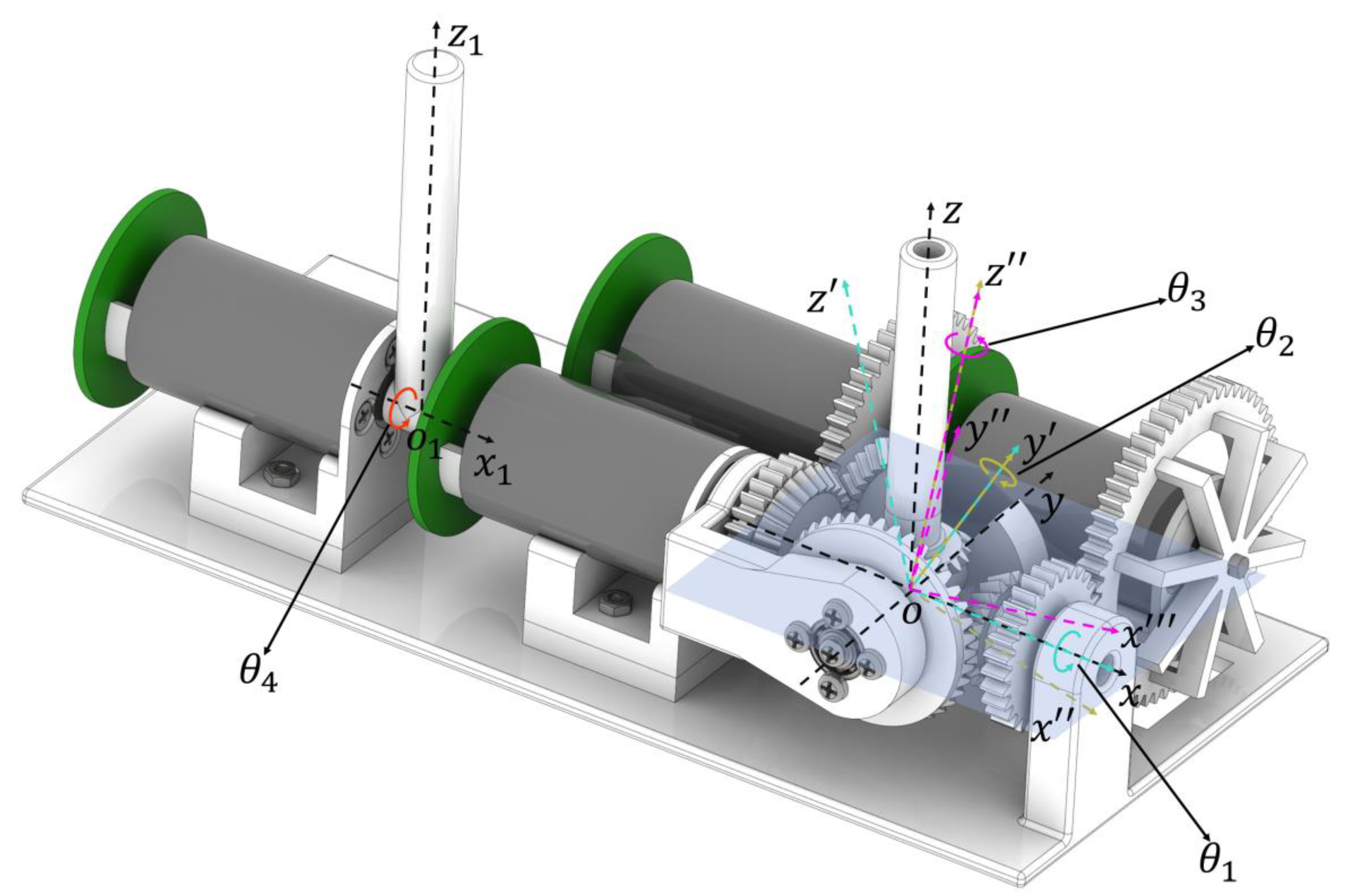
3. Kinematic Modeling
The kinematic model of the proposed haptic joystick illustrates the relationship between the encoder angles of the motor and the output stick angles for the operator. To display and control the posture of sticks more intuitively, the XYZ Euler coordinate systems bound to the rotation stick were used to describe the operation angles. The definition of coordinate axes and bending angles is shown in
Figure 3. The base coordinate is
and
, and the joint parameters are defined as follows:
where
are the angles around the
axes of the rotation stick, and
is the angle of the translation stick around
. The clockwise direction of the output shaft was defined as the positive direction of the motor rotation. The motor angles can be expressed as follows:
correspond to the angle of the pitch motor, the yaw motor, the roll motor, and the translation motor.
According to the joystick’s special mechanism, when controlling the rotation stick bending along one axis individually, the three motors need to move simultaneously to eliminate structure coupling. The change in the reference zero of the motors due to the coupling motion can be described as follows:
where
are the coupling gear ratios. They are related to the size of the gears on the mechanical structure. The size of the gears should be appropriate to avoid interference with other components and an increase in overall size. Considering the above factors, in the prototype they are −0.6, −0.5, and −1. The relationship from the motor angle to the stick angle is as follows:
are the transmission ratios from sticks to motors. In the prototype, they are designed as 1, −1, −1, and 1 to account for both output force range and back drive inertia.
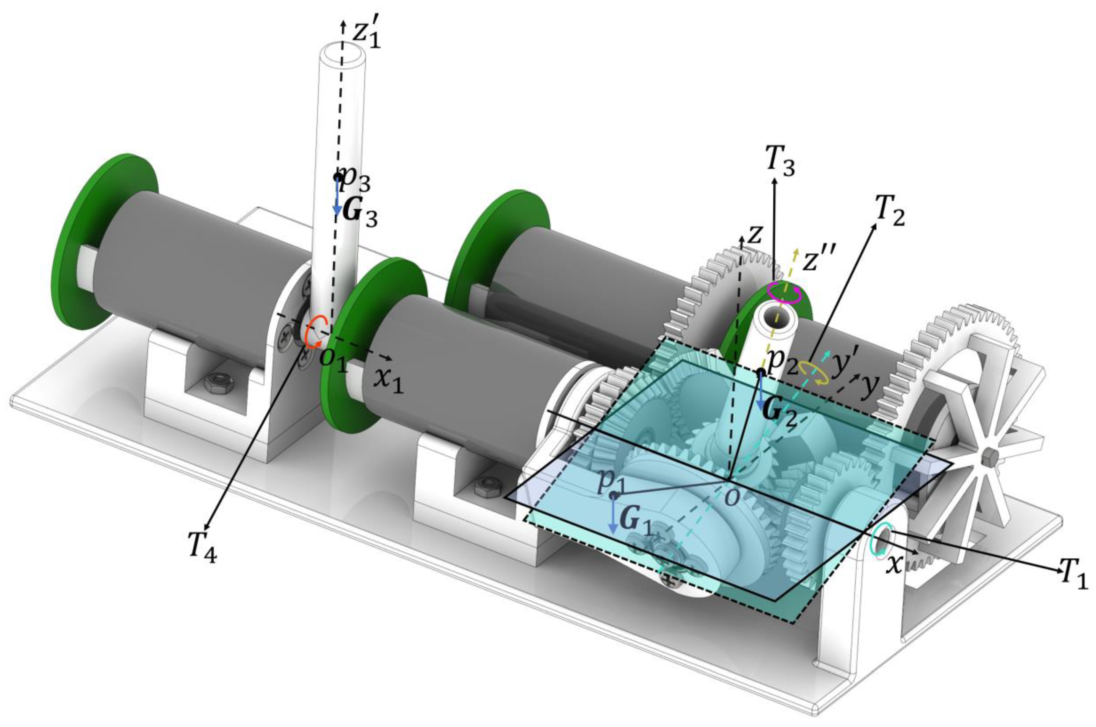
4. Static Force Modeling
Considering that flexible robots in the medical field are usually under low-speed quasi-static processes during operation, a static force model was created to set up the relationship between the motor outputs and the torques on the control sticks and realize gravity compensation. The torques on the control sticks are defined as follows:
where
are the torques along unit vectors
,
,
and
. As shown by the green, yellow, purple, and red arrow, respectively in
Figure 4, the directions pointed by the arrowheads are the positive directions of the torques.
The gravity of the rotation stick can be divided into two parts: the center of gravity for the structure of the pitch bracket and the roll transmit gear, and the yaw bracket is at
, which was designed to be on the plane
; its coordinate in
is
. The gravity center of the rotation stick
is located on the axis of
and its coordinate in
is
, while the center of gravity for the translation stick
is on the axis
and its coordinate in
is
. The gravity moments for
,
,
, and
are as follows:
are the gravity vectors. According to the principle of virtual work,
and
are the virtual displacement of the motors and rockers at each degree of freedom. The torques on the stick can be expressed as follows:
where
denote
, and the output torques of pitch motor, yaw motor, roll motor, and translation motor.
5. Robot Control and Haptic Feedback
This section aims to discuss the operation mode of the continuum-mechanism-based flexible robot and design an appropriate haptic joystick control method to conform to the clinical requirements. The requirements of continuum robot control for an application such as TEE can be divided into three parts. First, the operator can control all DOFs of the robot independently. However, different from the rigid structure, the continuum mechanism is easy to deform due to interaction with the tissue, which leads to the unfixed tip position. Second, for the continuum robot targeted at endoscopic-related applications, the task is to image and display the internal structure stably, most of which is a quasi-static process. As a result, it is critical that the robot remains stable even in the absence of doctor intervention. Finally, the motion scaling brought by the continuum robot is conducive to achieving fine control beyond the traditional manual operation; it is necessary to realize robot motion scaling more intuitively and conveniently. The requirement for continuum robot haptic feedback can also be divided into two parts. First, the perceptive operating force from the continuum robot can be transferred to the manipulator. Second, the haptic joystick can remain stable under different feedback forces.
Conforming to the above requirements, in this study, the mapping of the deflection angle of the haptic joystick to the speed on each DOF of the robot is used. It can be expressed as follows:
where
kmj and
denote the linear mapping parameter and the TEE probe motion speed for each DOF. The default value of
kmj is 1 and it can be set to any value theoretically. However, according to motor performance and safety, the values from 0.3 to 2 are recommended. In addition, to avoid reading instability caused by accuracy errors near the initial position and to eliminate hysteresis effects, a dead band of 5° was set. In this control mode, the operator does not have to keep their hands suspended, which can reduce hand tremors and fatigue. Moreover, motion scaling can be easily achieved by regulating
kmj.
For force regulation, impedance control is a stable and intuitive method [
25]. Considering that the haptic joystick needs to adjust the output force based on the force perception of the robot, variable impedance control is used in this study [
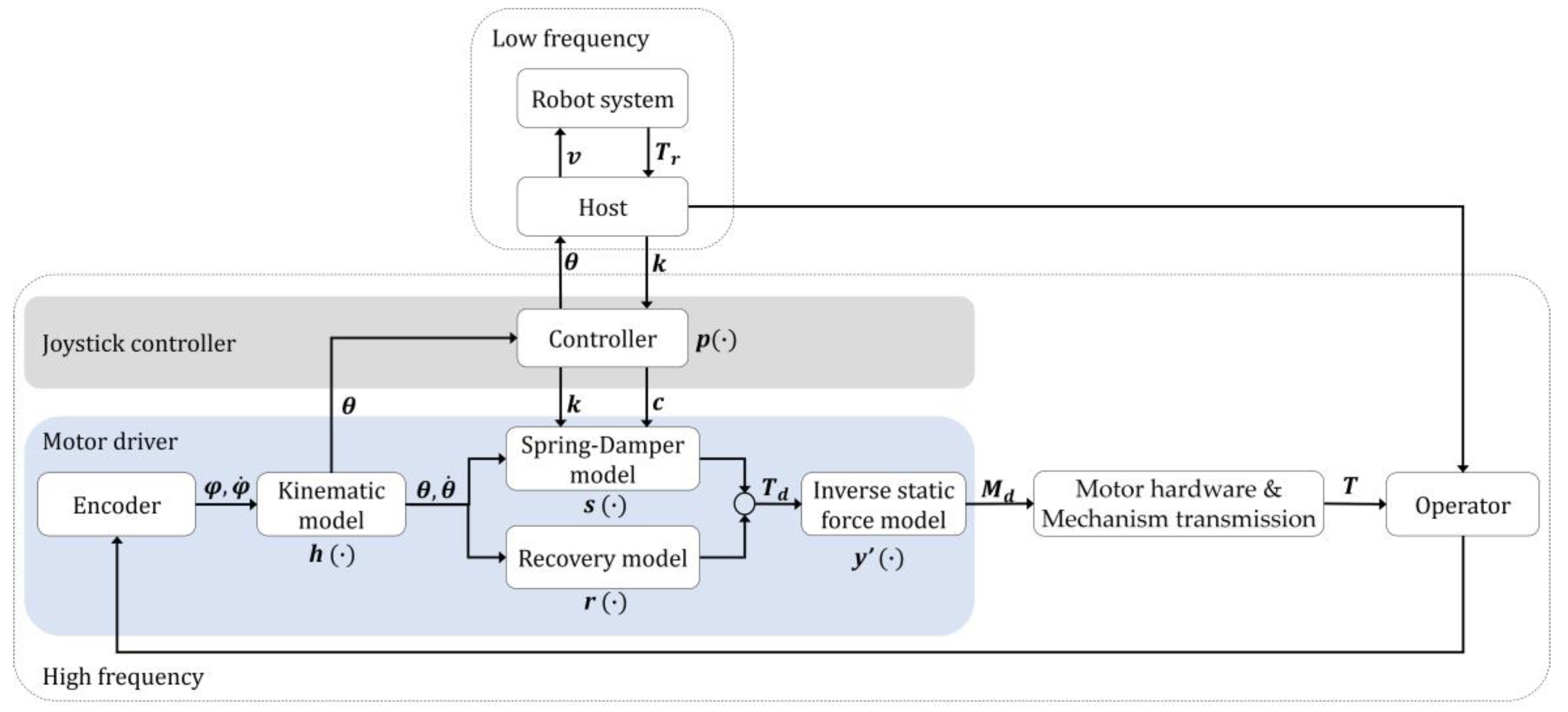
26]. The control diagram of the haptic joystick is shown in
Figure 5. The state of the haptic joystick is obtained by the encoder, and the deflection angles of the control stick
obtained from the kinematic mode are used as the input signal for the robot control. The operational torques of the robot
is as follows:
where
and
denote the operational torques for the anteflex–retroflex and left–right bending of the continuum mechanism. Since the robot used in this study only has force-sensing capability for the bending axes, only two-DOF tactile feedback was implemented on the haptic joystick to verify the feasibility of the proposed system. Linear mapping was employed from the operational torques to the elastic coefficient
:
where
and
are the elastic coefficients in the pitch and yaw direction of the haptic joystick, and
and
are the force mapping constants. The torque in the handwheels sensed by the robot is no more than 0.45 Nm in a single direction [
24] and the joystick output torque is less than 0.086 Nm in each DOF. The values of
and
are determined by mapping the robot torque to the joystick according to the torque range and the joystick motion range. Their values were all set to 0.11 according to the 100° maximum angular deflection range tested by experiments. The angle was in radians during the calculation.
The joystick controller was used to change the damping coefficient
according to the elastic coefficient.
was used to keep the system stable in motion:
where
and
are the damping coefficients in the pitch and yaw direction of the haptic joystick, and
and
are the stable constants. The values of
and
are used for preventing oscillation when the system restores its initial state. They were set to 0.07 according to the practical tests. The robot system’s communication frequency was only 15 Hz due to wireless latency and the robot response; however, the joystick controller’s control frequency can reach 500 Hz, and linear interpolation was used in the joystick controller to ensure a smooth force output. When receiving the operation torques of the robot,
k and
c approach the expected value from the current value gradually in a fixed step. The update frequency of
k and
c is 500Hz and the step of
k is 5 × 10
−4 to ensure both smoothness and response speed such that any value within the range can be reached within 0.5 s. The elastic coefficient and damping coefficient exported by the joystick controller were converted into the output torque through the spring-damping model
:
where
s is the expected torque of the spring-damping model in each DOF. Furthermore, when the joystick is under unmanned control, the haptic joystick needs to automatically recover to its initial state to avoid the safety hazard. In this study, an autonomous recovery strategy based on another spring-damping model
was applied:
where
r,
,
, and
are the expected torque of the recovery spring-damping model in each DOF, the recovery elastic coefficient, recovery damping coefficient, and maximum recovery torque. The increase in the recovery torque was set within the motion dead zone range. When the stick exceeds this area, the recovery torque will become constant
to avoid interference with stiffness changes caused by robot torque. The
was set to 10% of the maximum output torque, according to the dead zone of 5°;
is 0.098 Nm/rad and
is numerically 0.07 times the maximum torque
. The expected output torques on the stick
are the combination of
and
. After the inverse static force model
, the expected motor torques were calculated for motor control, while
was the inverse matrix of the static force model
. The motor output torques were transmitted to the operator through the mechanical structure.
6. Experiments and Results
6.1. Accuracy and Workspace
This section aims to test the position accuracy and workspace of the proposed haptic joystick to evaluate its basic performance in practical applications. An angle sensor was connected to the rotation stick. The stick rotated for one cycle, including positive and negative directions. The errors were calculated by comparing the difference between the angle sensor and motor angles. The accuracy of three rotation directions was tested separately. The workspace was tested by controlling the stick to the extreme position manually and recording the motor angle in the pitch and yaw directions. The data were recorded for further analysis. The roll motion range was 360°, so there was no need for specific testing.
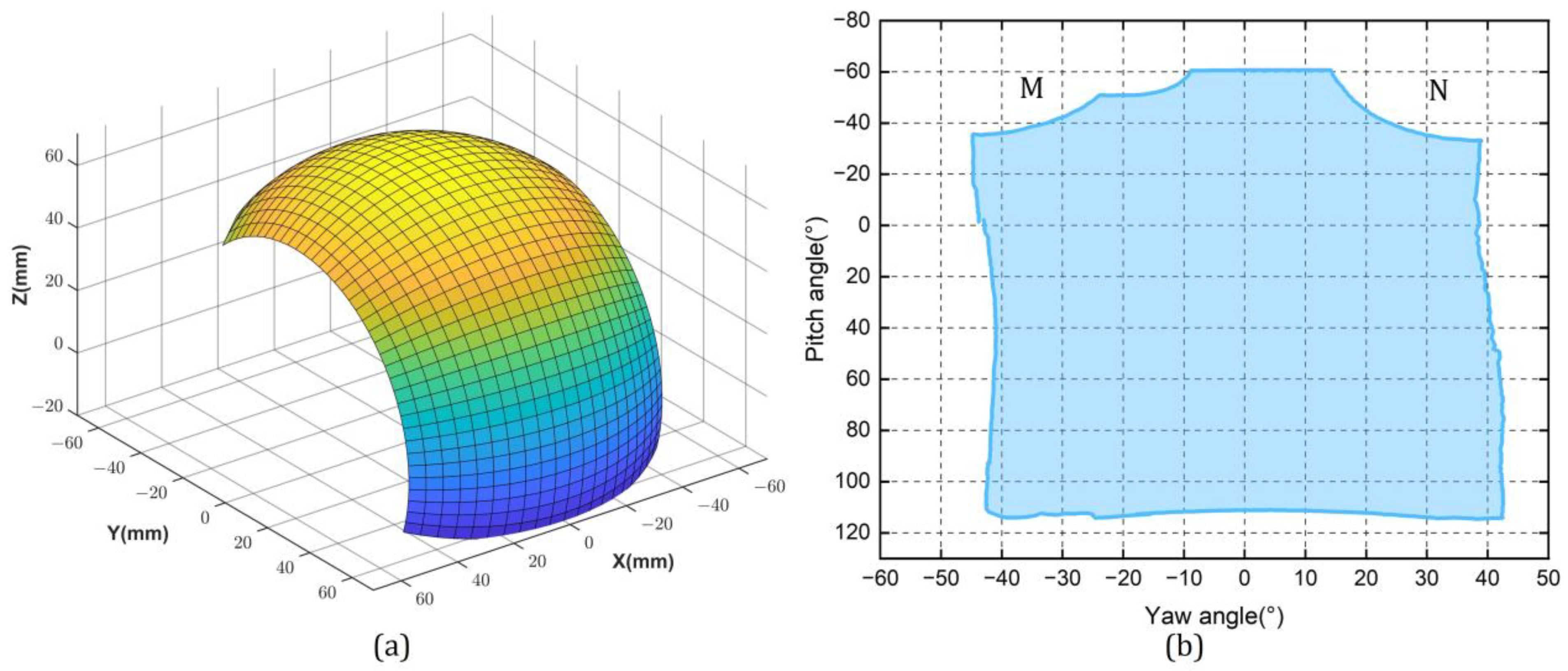
The mean absolute deviation and standard error of the joystick in pitch, yaw, and roll were 0.33° ± 0.42°, 0.71° ± 0.84°, and 0.54° ± 0.64°, respectively. The workspace of the joystick proposed is shown in
Figure 6 under Cartesian space and joint space for pitch and yaw direction. The maximum ranges in the pitch and yaw angle were −60° to 110° and −40° to 40°. The absence of workspace in parts M and N was caused by the interference between the roll motor and the rotation stick. It should be noted that regardless of the state in which the joystick was held, the ranges of motion in the roll and translation directions were −180° to 180° and −90° to 90°, respectively.
6.2. Torque Output Performance
This section aims to test the force output performance under gravity compensation to validate the accuracy of the static force model under the different joystick rotation states. The unknown parameters of Formula (12) need to be confirmed by an experiment before further assessment. When the stick output torque
T is zero, the formula can be transformed to
The above equation can be further converted to
The gravity parameters can be measured by the record current angles and motor output torques M. To ensure that R is reversible and the measurement noise is not amplified, the should be set to near zero and should be larger.
The joystick output torque experimental setup is shown in
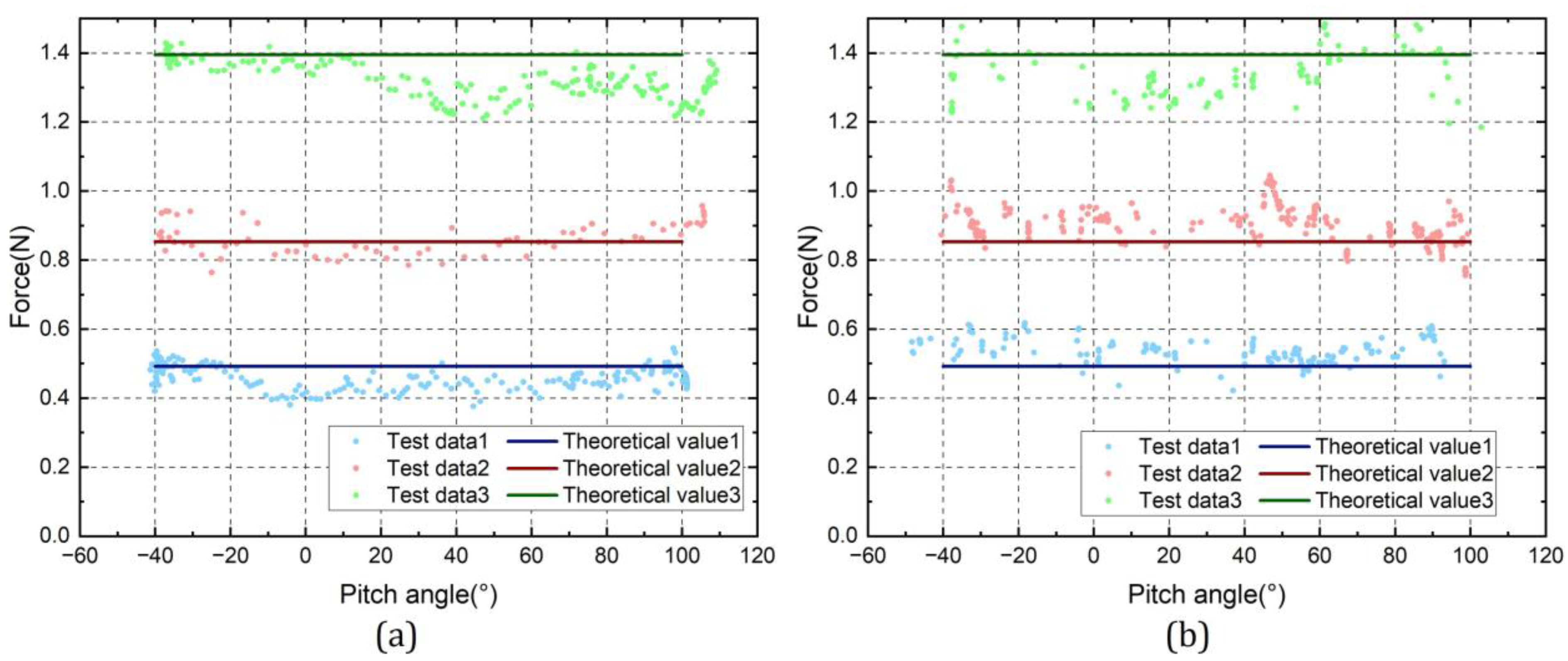
Figure 7. A force sensor (6-axis, M3552B, Sunrise Instruments, Shanghai, China) was fixed on the rotation stick to measure the force at the tip. The pitch motor and yaw motor were set to export a constant force to the tip of the control stick. The torque output accuracy of the haptic joystick was evaluated by recording the force sensor’s input force in the pitch and yaw directions when the rotation stick remained at different pitch angles.
The output performance results are shown in
Figure 8.
Table 1 shows the mean value and standard deviation of the theoretical value and the measured value. It can be identified from the table that the standard deviation of the actual output force compared with the theoretically calculated value is within 8%, and the error increases as the output force increases. Experimental results show that the proposed haptic joystick can effectively output different magnitudes of forces in a small range.
6.3. Robot Control and Haptic Feedback
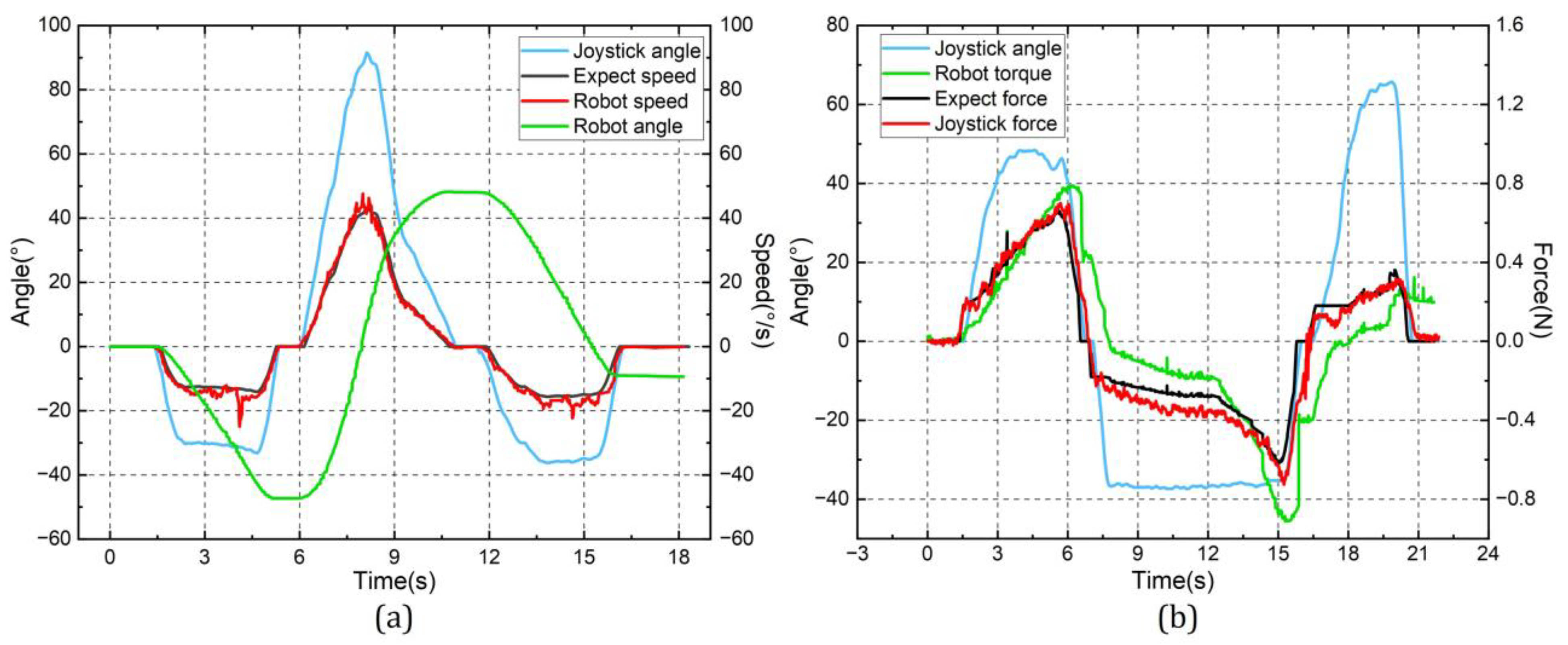
This section aims to test the control function of the haptic joystick for the continuum robot and the haptic feedback effect of the robot on the haptic joystick to evaluate its practicality. During the robot control experiment, the host received the deflection angle of the joystick, converted it to the expected speed, and sent it to the robot. The deflection angle of the joystick and the joint angle of the robot were recorded for further analysis. During the haptic feedback experiment, the joystick controlled the robot to bend. Resulting from the inherent resistance inside the continuum structure, the operational torque would increase gradually. A force sensor was fixed on the rotation stick to measure the feedback force. The robot operation torque, the joystick angle, and the feedback force were recorded for further analysis.
The experimental results are shown in
Figure 9. To avoid sudden changes in speed calculated using measured handwheel angles, the robot speed was processed using the Savitzky–Golay filter. The window length of the filter was 7 and the polynomial order was 3. The mean absolute error in speed was 1.36°/s and the standard error was 1.79°/s. The experimental results show that the haptic joystick has a good control effect on the slave robot, and it was identified that the expected speed is in good agreement with the measured speed. At the same time, the torque sensed by the robot can be fed back to the master. The mean absolute error in tip force is 0.055 N and the standard error is 0.075 N. The haptic feedback results show that the test output force has a good correlation with the expected output force on the proposed haptic joystick.
7. Discussion
In this paper, we propose a new design method of the haptic joystick considering the motion characteristics and operation demands of continuum robots for medical application, and we conduct systematic analysis and testing for its modeling and control. Specifically, kinematic and static models were implemented at the motor driver level to improve the speed of position and force response. To verify the effectiveness of the proposed haptic joystick, we used an existing continuum robot, i.e., the trans-esophageal ultrasound robot, to conduct experimental tests. As can be seen from the previous section, the analysis and experimental results show good effects of control and haptic feedback. Moreover, the haptic joystick and its control method proposed in this paper can be simply transferred to other robots, especially for interventional or endoscopic robots that access the human body via natural orifices. Furthermore, the position–velocity mapping method improves the stability of the operation and avoids the hand jitter of operators effectively, which conforms to the motion characteristics of this type of robot. The haptic feedback method proposed in this study based on variable impedance control combines the information of the master control speed and the slave force perception, which is more consistent with the scenario of clinical application.
In contrast to existing commercially available general-purpose multi-degree-of-freedom haptic devices, the device design and control approach proposed in this paper were developed completely for the motion characteristics of medical continuum robots. This makes it more intuitive to operate this type of robot, while avoiding the suspension, fatigue, and jitter of human hands. Compared with the gimbal-structure-based haptic joystick, the design illustrated in this paper extends to three-DOF haptic feedback on a control stick under the condition of maintaining the same small tip inertia. In addition, the design proposed in this paper has improved compactness on the basis of achieving the same amount of workspace output. Compared to our previous work where a custom handle [
27] or gamepad [
28] was used to control the trans-esophageal ultrasound robot, the method proposed in this paper provides real haptic feedback, which is a huge enhancement for this type of application.
Calculated from the maximum output torque of the motor and the stick length parameters, the maximum output force at the tip is about 1 N in a single direction. According to the actual application, it is sufficient to sense the changes in force in the tip and without causing fatigue during prolonged operation. One problem of this configuration is that when the rotation stick outputs torques in three directions simultaneously, it can be obtained from the static model that the coupling of the output forces may cause the maximum output torque in a single direction to decrease to 40% of the motor maximum torque. While in the control of continuum robots, the more common mode of operation is single-axis movement. Furthermore, the tip force can be enhanced by decreasing transmission ratios .
According to the results of the accuracy test, the error on each DOF is within 1.6°. The primary reasons are the axial clearance of the bearing when the yaw bracket is supported on one side, as well as the assembly error of the gears. The result of the torque output performance shows that the test output force has a good correlation with the expected force, and the error in the force output is likely to be the result of directional changes in the output force caused by the position error. Further modifications to the structure and the replacement of higher-precision bearings could optimize the aforementioned problems. The results on robot control and haptic feedback show that the haptic joystick can control the motion of a continuum-mechanism-based medical robot effectively by combining the control input and robot force sensing to achieve reasonable tactile feedback.
For future work, the tactile feedback of the joystick can be combined with the prediction of the continuum robot contact force, which has been studied in our previous work [
24]. The predicted contact force at the tip could be interpreted as the input of the haptic joystick, which can filter out the internal resistance of the continuum mechanism and present the contact force at the tip to the doctor more intuitively.
8. Conclusions
This paper introduces the design of a novel 4-DOF haptic joystick for the teleoperation of continuum-mechanism-based medical robots. The kinematic and static models were analyzed for position perception and gravity compensation. A framework that combines position–velocity mapping and variable impedance haptic feedback was realized. As a result, the proposed haptic joystick can intuitively and easily control a selected experiment robot, i.e., a trans-esophageal ultrasound robot, while at the same time improving the safety of the teleoperation process through tactile feedback.


