Article

Estimation of Knee Assistive Moment in a Gait Cycle Using Knee Angle and Knee Angular Velocity through Machine Learning and Artificial Stiffness Control Strategy (MLASCS)

by
Khemwutta Pornpipatsakul
and
Nopdanai Ajavakom
*
Department of Mechanical Engineering, Faculty of Engineering, Chulalongkorn University, Bangkok 10330, Thailand
*
Author to whom correspondence should be addressed.
Robotics 2023, 12(2), 44; https://doi.org/10.3390/robotics12020044
Submission received: 2 February 2023 / Revised: 10 March 2023 / Accepted: 14 March 2023 / Published: 17 March 2023
(This article belongs to the Topic Intelligent Systems and Robotics)

Abstract

:
Nowadays, many people around the world cannot walk perfectly because of their knee problems. A knee-assistive device is one option to support walking for those with low or not enough knee muscle forces. Many research studies have created knee devices with control systems implementing different techniques and sensors. This study proposes an alternative version of the knee device control system without using too many actuators and sensors. It applies the machine learning and artificial stiffness control strategy (MLASCS) that uses one actuator combined with an encoder for estimating the amount of assistive support in a walking gait from the recorded gait data. The study recorded several gait data and analyzed knee moments, and then trained a k-nearest neighbor model using the knee angle and the angular velocity to classify a state in a gait cycle. This control strategy also implements instantaneous artificial stiffness (IAS), a control system that requires only knee angle in each state to determine the amount of supporting moment. After validating the model via simulation, the accuracy of the machine learning model is around 99.9% with the speed of 165 observers/s, and the walking effort is reduced by up to 60% in a single gait cycle.

1. Introduction

Too much walking, running, sitting, and standing can cause body pain, particularly knee pain. It is quite common because the knees carry the whole upper body weight in most human movements. If people have knee discomfort, it will significantly impact their daily lives, such as trouble walking/running/sitting, etc., or a lack of confidence in doing basic chores [1]. Furthermore, several people have knee impairments, such as muscle weakness, pain, and paralysis resulting from a spinal cord injury, severe injury, or other syndromes [2,3].
To handle knee problems, many knee devices have been built. Knee reinforcement devices are usually mechanical or electromechanical in general. Importantly, the goal of the knee reinforcement device is to increase the user’s loading capacity or to decrease the user’s metabolism during various mobility tasks [4]. When the user wears the device, it should be comfortable and supportive [5].
According to former studies by Zhang et al. [6] on the attachment position of all knee devices, approximately 38% of all devices is the lateral support layout (outside) type [7,8,9,10,11,12,13,14,15,16,17,18,19,20,21,22,23,24,25,26,27,28,29]. The two-side support devices are used approximately 10% of all [3,30,31,32,33,34]. The improved-lateral support type is used by 40% [35,36,37,38,39,40,41,42,43,44,45,46,47,48,49,50,51,52,53,54,55], while the remaining devices are anterior/posterior support type [6]. According to the movement of the knee, the most significant factor that should be considered is how the device’s mechanism flexes and extends the knee [6]. A research article proposes that the knee joint can be modeled as a four-bar linkage mechanism with a maximum center of rotation error while walking is around 1.08 mm [56]. Moreover, in a normal gait cycle, the knee angle may not exceed 70 degrees [57], so the position of the center of rotation may not change substantially. Note that the center of rotation is an instantaneous point where the upper leg and lower leg flex or extend around.
Zhang et al. also suggested that many studies of knee assistive devices use different actuation types [6]; around 73% of the research uses active actuation [3,7,8,9,10,11,12,13,14,15,16,17,18,19,20,21,22,23,30,35,36,37,38,39,41,42,43,44,45,46,47,48,58,59,60,61,62,63,64,65,66,67], 10% uses quasi-active actuation [24,25,26,49,50,51,52,55], and 17% uses passive actuation [27,28,29,31,32,33,34,53,54,68,69]. A device that uses an electric or pneumatic actuator as a power source is known as active actuation. A passive actuation device operates solely on the potential energy of the device structure, whereas a device that uses a combined actuator and the concept of the passive device is known as a quasi-active actuation. Moreover, in some previous gait rehabilitation and human performance augmentation applications [70], they generally used pneumatic artificial muscles (PAMs) [3,47,48,71], series elastic actuators (SEAs) [40,55,58,72,73], motors [45,46,61,67], and regenerative magnetorheological actuators (RMRAs) [74,75].
Control techniques are necessary during knee exoskeleton development in every actuation type because of the physical connection between the wearer and the device. The assistive moment can be generated corresponding to the wearer’s movements and intention with the control strategy for ensuring the safety and comfort of the wearer. Different control strategies for knee exoskeletons have been suggested, for example, the position-based trajectory tracking control, the assist-as-need control, and the bioelectric signals-based control [70]. The control techniques of the former studies used are (1) hybrid position/force control by using a gauge pressure sensor [48] and applying the rotary and linear encoder [47] to configure the support moment; (2) the force control [72,73], to apply precise force or torque to the device; (3) bounded control [45,46] that increases safety and prevents actuator saturation; (4) impedance control [40,58,61,67] which maps the desired trajectory and the stiffness; (5) position control [55,74,75], tracking normal patterns of walking and operating the device; (6) bioelectric signals-based control [3] that merges the relation between muscle activity and human movement; (7) on–off control [71] that generates and degenerates support in a specific condition.
From human gait cycles, the knee angle, an angle between the thigh leg and shin leg where it is 0 when two sections are parallel, is between 0 and around 70 degrees [57], so the range of motion of the device should smoothly operate between these degrees. The knee joint acts as a pivot joint between the thigh leg and shin leg, while the quadriceps muscles operate across it [76]. Dynamic and static stability of the knee joint can be controlled by muscles, tendons, and ligaments [77]. In addition, the joint can be assumed as a four-bar linkage [1,56,78] with a moving center of rotation point. The joint is stable because the muscles and ligaments [2,3] act as a dampener. There are two basic phases in a normal human gait cycle: stance phase and swing phase, with the stance phase being further divided into the weight acceptance phase and terminal stance phase [70], as shown in Figure 1 (modified from [70]). The weight acceptance phase occurs when a foot begins to lie on the ground and sends body weight to the ground for balance. This phase ends when the foot fully presses the ground. The terminal stance phase starts when the foot begins to kick the ground to continue walking. The swing phase occurs after the foot has been propelled off the ground. It is the phase in which a foot does not touch the ground and swings for preparing the next weight acceptance phase. Figure 2 shows the plots of human knee joint angle and moment per body mass during a gait cycle from modified raw data [57]. The maximum knee moment per body mass is around 0.67 Nm/kg. Note that the flexion moment is negative.
A possibility of whether the stance and swing phase can be predicted by the angular velocity of the lower leg was presented by Grimmer et al. [80]. Attaching five inertial measurement units (IMUs) makes it possible to detect the stance phase while applying additional rule sets. The relative velocity between a thigh and shin leg was also suggested by Javanfar et al. [81]. The relative motion between the femur and tibia can be analyzed by the collision reactions of the knee’s cartilage and bone. The results can suggest a design concept for a knee device.
The machine learning technique has been used for improving a knee device. Mokri et al. [82] can estimate a muscle force from the prediction of several machine learning methods, while the input is data from surface electromyography (sEMG) signals. This method can improve the performance of therapy and increase the sensitivity between the muscle model and the tendon stiffness. Machine learning was also applied for helping people with missing legs [83]. The study showed that the data from a series of foot pressure sensors can be used to predict the walking phase through the k−nearest neighbor (kNN) algorithm. Not only can healthy gait be detected by a machine learning model, but an abnormal gait can also be predicted. Chen et al. presented that their algorithm can predict the probability of elderly flat ground, which is helpful for the rehabilitation monitoring [84].
The control techniques usually require many sensors to control knee devices because of the complexity of movement, as the knee flexes and extends both when the foot touches and do not touch the ground. Nowadays, actuators combined with an encoder can give feedback on the motor’s current angle and the angular velocity of the joint. For reducing the number of sensors in the device, this research proposes the machine learning and artificial stiffness control strategy (MLASCS) by using the knee angle and the knee angular velocity with machine learning and an artificial stiffness techniques for controlling the amount of supporting moment of the knee assistive device in a gait cycle. The machine learning model is introduced to classify the state of a gait cycle for mapping the amount of stiffness to support the required knee moment. This study explains how to create the MLASCS and validates the efficiency of this strategy by simulating the effort used when walking with and without MLASCS. The results of this study can indicate if machine learning can be applied for finding a state of gait, the amount of supporting knee moment, and if the MLASCS can be used for knee devices, knee robotic systems, and humanoid robots.
The paper is organized as follows. Section 2 describes how to collect and prepare data for calculations. Section 3 gives details on the creation of the MLASCS composed of machine learning and artificial stiffness control techniques. In Section 4, the simulation and validation of the MLASCS are shown. The results and discussion are displayed in Section 5. Finally, Section 6 concludes all the details of the study and discusses future work.

2. Knee Joint Data Collection of Walking Gait Cycle

Even though there is a lot of recorded knee joint data on a normal human gait cycle, there still might not be much knee data measured on Asian people which differs from data on Western people. Therefore, the data in walking gaits are measured in our research laboratory to make sure that the number of data points is large enough for creating a machine learning model.

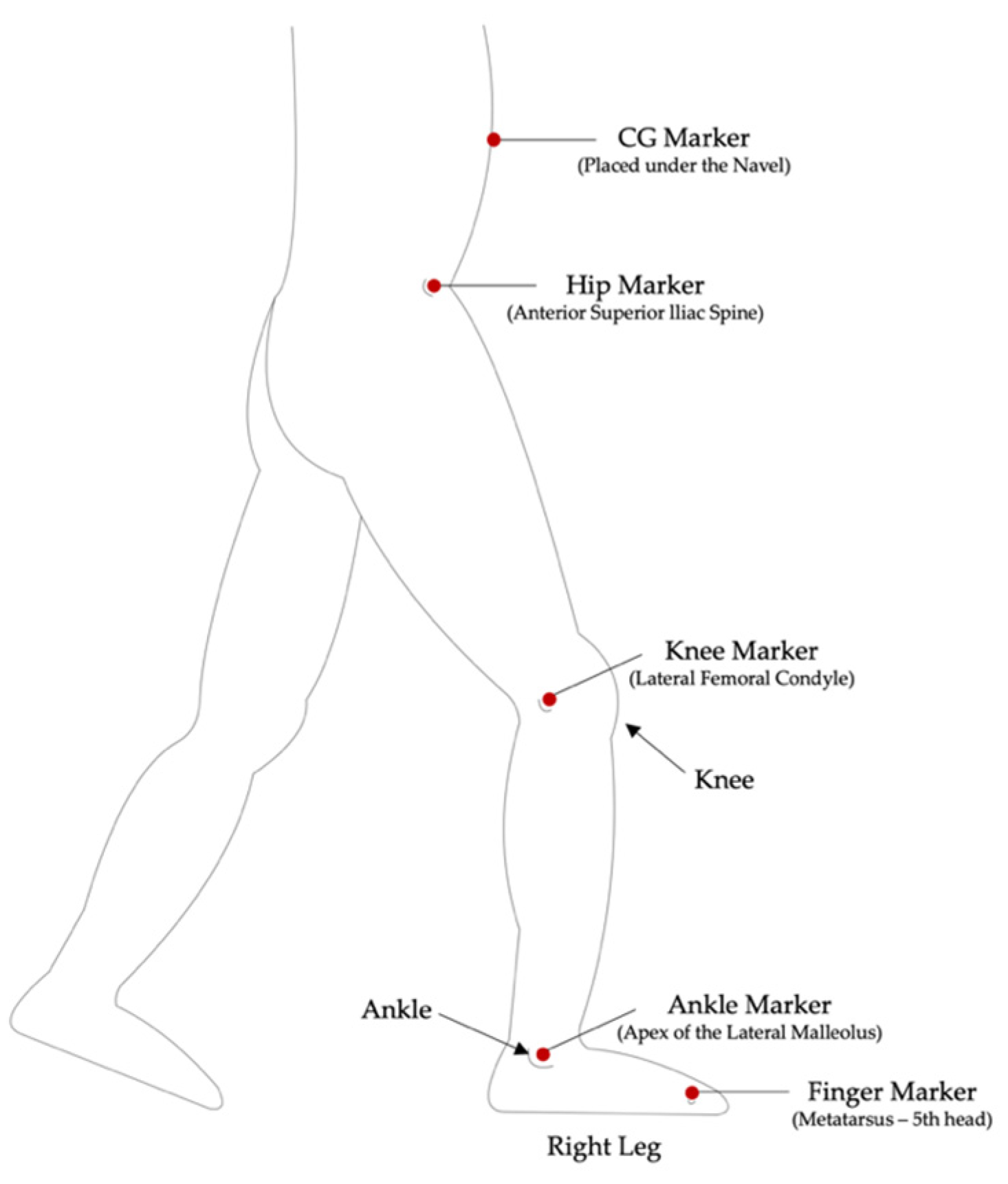
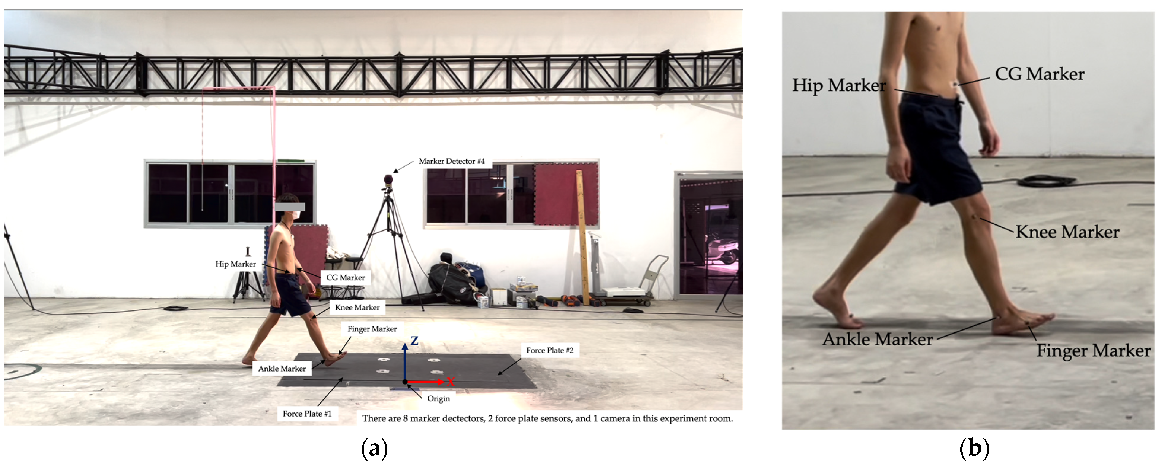
2.1. Data Collection

The information on knee angle and moment are necessary to analyze and understand a human gait cycle for creating assistive knee motion devices. The knee moment can be determined by a ground reaction force (GRF) using inverse kinematics calculations. One effective way to determine knee movement and ground reaction force is from a motion capture sensor and force plate sensors. In the motion capture device, markers should be placed at the proper positions during measurement. According to the recommendations by Robertson et al. [85], there should be at least two positions in each segment, for example, in the lower leg the markers should be near the knee and the ankle so that the angular velocity can be determined. Therefore, the CG, the hip, the knee, the ankle, and the finger markers were attached at the positions shown in Figure 3. In addition, the average walking speed of all participants was approximately 1.5 m/s.
The CG marker is attached at around 0.412 of sample height (proximal) following the recommendation by Robertson et al. [85] to estimate the precise walking speed of the sample. The hip, the knee, the ankle, and the finger markers were attached to measure each 3D position, following the Qualisys Software Manual, for calculating knee and ankle angles. In this experiment, three participants were measured for nine trials in total. The participants are Thai adults whose average age is 23, whose height is 171–172 cm, and whose weight is 51.9–61.8 kg. The measurements also included two force plate sensors on the ground to measure the GRF. The experiment room has 16 marker detectors, 2 force plates, and 1 camera. The experiment room with markers attached to the participant is shown in Figure 4.

2.2. Data Analyzing

The sampling frequency of the motion capture is around 240 Hz. MATLAB was used to resample the recorded data to have the same data points. The noise is also eliminated by MATLAB.

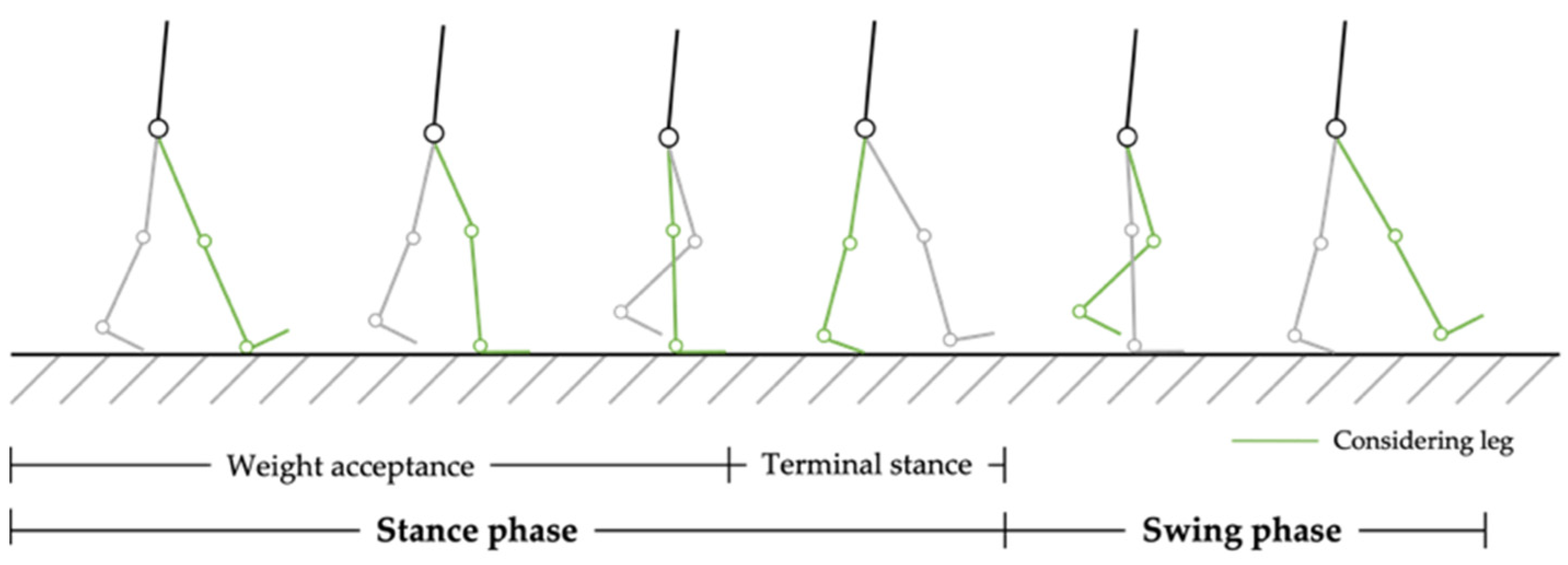
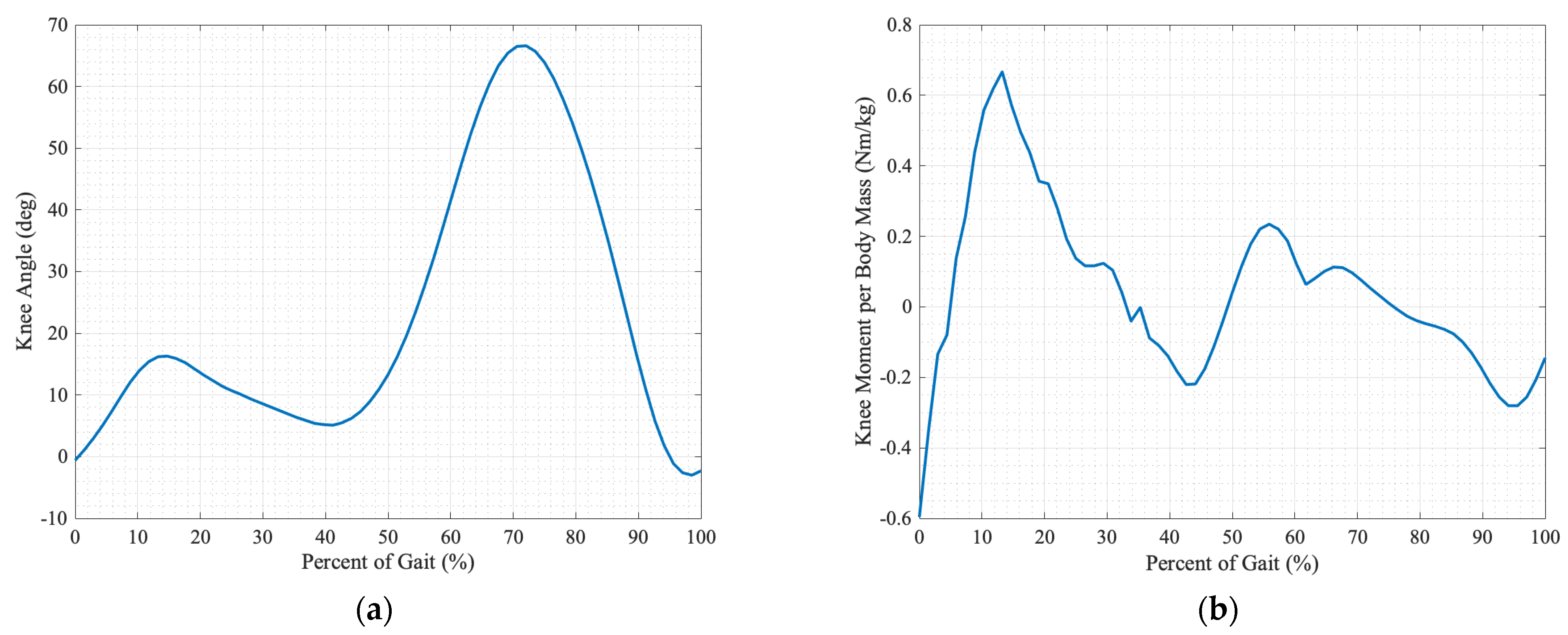
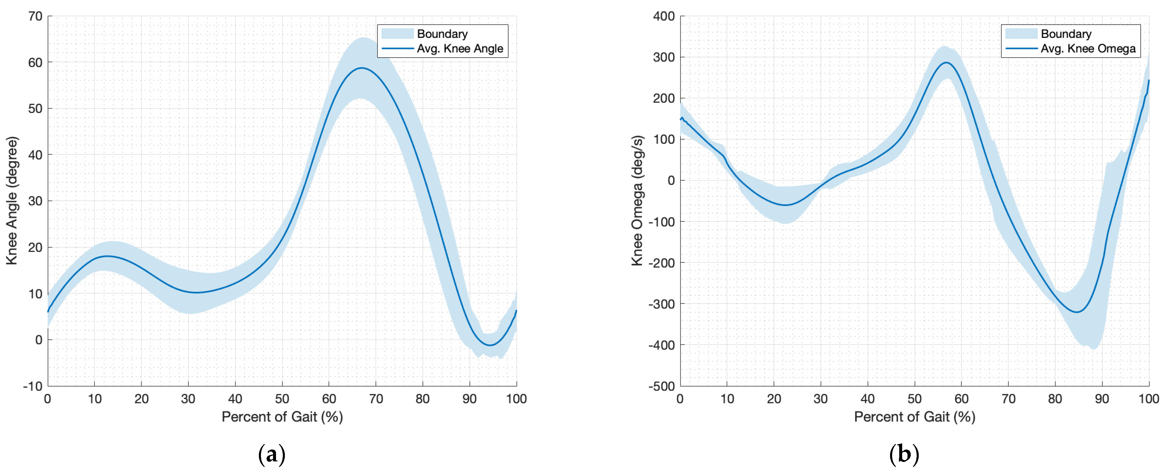
2.2.1. Kinematics of Knee

The raw data of the CG, the hip, the knee, the ankle, and the finger markers are represented in 3D positions in which the knee angles and ankle angles are determined. The slight variation in the y-axis data is negligible and, thus, only data in the X–Z plane is analyzed. Because all of the collected data are positions and angles, it is necessary to calculate velocity and acceleration for further calculations. The centered finite difference (CFD) method with an accuracy of order four was used to calculate velocity and acceleration. The regular CFD equation is as follows [86]:
f ( x ) = [ f ( x + h )     f ( x     h ) ] 2 h
It can be calculated for more accurate prediction in the first derivatives for velocity, as follows [87]:
f ( x ) = [     f ( x + 2 h ) + 8 f ( x + h )     8 f ( x     h ) + f ( x     2 h ) ] 12 h
and second derivatives for acceleration [87], as follows:
f ( x ) = [     f ( x + 2 h ) + 8 f ( x + h )     8 f ( x     h ) + f ( x     2 h ) ] 12 h 2
where x is the time values, f(x) is the function, f′(x) is the first derivative function, f″(x) is the second derivative function, and h represents the small step time.
It was found that the collected data on knee angle has some noise; therefore, all knee angle data required post-process signal processing before determining the knee angular velocity (knee omega). The average of the processed knee angles and knee omegas with the boundaries of all nine trial data are shown in Figure 5, whereas the starting position is when the heel touches the force plate.

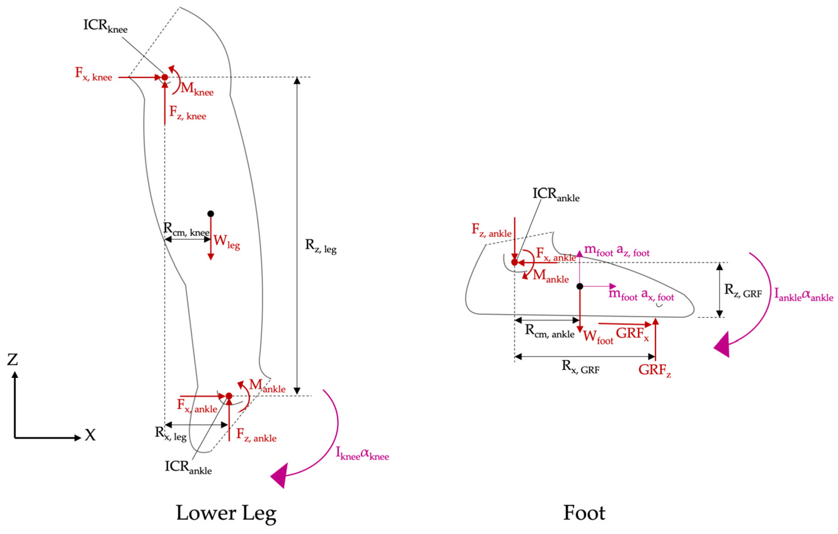
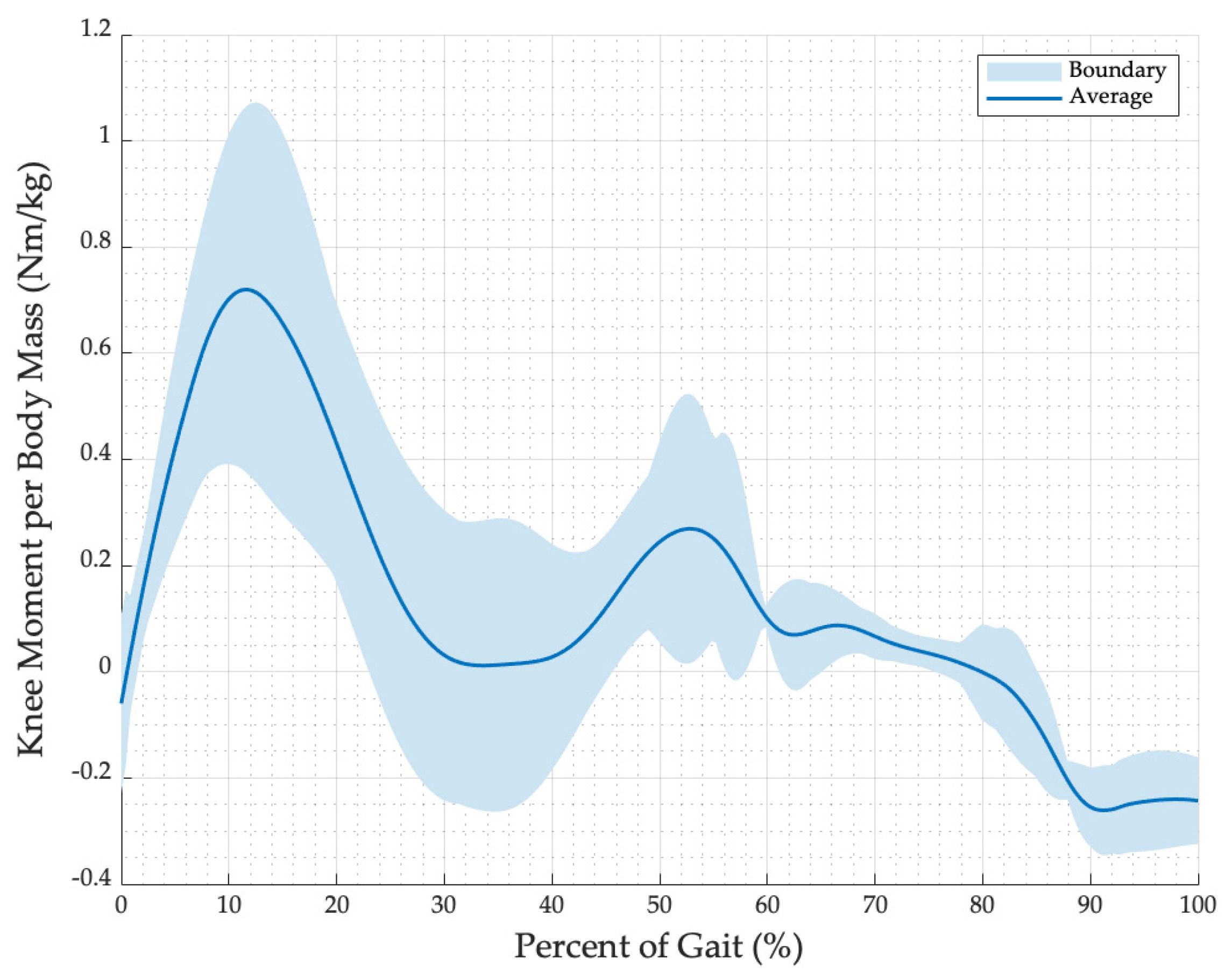
2.2.2. Kinetics of Knee

The following is the process for calculating knee moment (Mknee) from the GRF. All equations are modified from Newton’s 3rd Law (Equations (4) and (5)) for planar motion where the free body diagrams of the lower leg and the foot are shown in Figure 6. There are two steps in this calculation. The first step is the calculation of both the x and z directions of the ankle reaction force (Fx, ankle and Fz, ankle) and the ankle moment (Mankle) from the x and the z directions of the GRF (GRFx and GRFz) shown in Equations (6)–(8). Equations (4) and (5) are as follows:
  F = ma
  M G = I α
where   F represents the summation of all the forces that act on the body, m is the mass of the body, and a is the acceleration of the body.   M is the summation of all action moments exerted on the body around a specific point (G), the I is the moment of inertia of the body around the point, and the α is the angular acceleration of the body around the point. From the free body diagram of the lower leg and foot shown in Figure 6, the forces on the ankles can be calculated by the following equations:
F x , ankle = GRF x     m foot a x , foot
F z , ankle = GRF z     W foot     m foot a z , foot
The moment around the ankle is as follows:
M ankle = GRF z ( R x , GRF ) + GRF x ( R z , GRF )     W foot ( R cm , ankle ) + I ankle α ankle ,
where GRF x and GRF z are the ground reaction force in the x and z directions, respectively. The Rx, GRF and Rz, GRF are the lever arm distance between the instantaneous center of rotation of the ankle (ICRankle) and GRFx and GRFz, respectively. Note that, the position data of the ankle marker, placed at the apex of the lateral malleolus, was used as the position of the ICRankle in this calculation. The mass mfoot is the estimated mass of the foot, which is approximately 0.0145 of body mass (mbody) [85]. Here, ax, foot and az, foot are the accelerations at the foot’s center of mass in the x and z-directions, Wfoot is the weight of the foot, Rcm, ankle is the lever arm distance between the ICRankle and Wfoot, Iankle is the moment of inertia around ICRankle of which the radius of gyration is approximately 0.690 of the foot length [85], and αankle is the angular acceleration of the ankle. All positions of the variables are shown in Figure 6, where Fx, knee and Fz, knee are the knee reaction forces in the x and z direction, respectively. Hence, the moment of the knee Mknee can be calculated from the Fx, ankle, Fz, ankle and Mankle via the following equation:
M knee = W leg ( R cm , knee )     M ankle     F z ,   ankle ( R x ,   leg )     F x ,   ankle ( R z ,   leg ) + I knee α knee ,
where Wleg is the weight of the lower leg, which is approximately 0.0465 of body mass [85], Rcm, knee is the level arm distance between the instantaneous center of rotation of the knee ICRknee and Wleg, Rx, leg and Rz, leg are the lever arm distances between ICRknee and Fx, ankle and Fz, ankle, respectively, Iknee is the moment of inertia around ICRknee of which the radius of gyration is approximately 0.528 of the lower leg length [85], and αknee is the angular acceleration of the knee.
The knee moment per body mass (MPBknee) during a gait cycle of all trials can be determined from the knee moment (Mknee) and the body mass (mbody), as follows:
MPB knee = M knee m body .
The average and the boundaries of the calculated knee moment per body mass are shown in Figure 7, whereas the knee extension moment is positive, and the knee flexion moment is negative. Even though the results are slightly different from the previous study by Winter [57], the trends of all knee moments are quite similar. The difference in the results might be from differences in step lengths, foot shapes, stride shapes, etc. Even the same person can have different knee moment paths in each step, so it may be normal if different people have different knee moments.

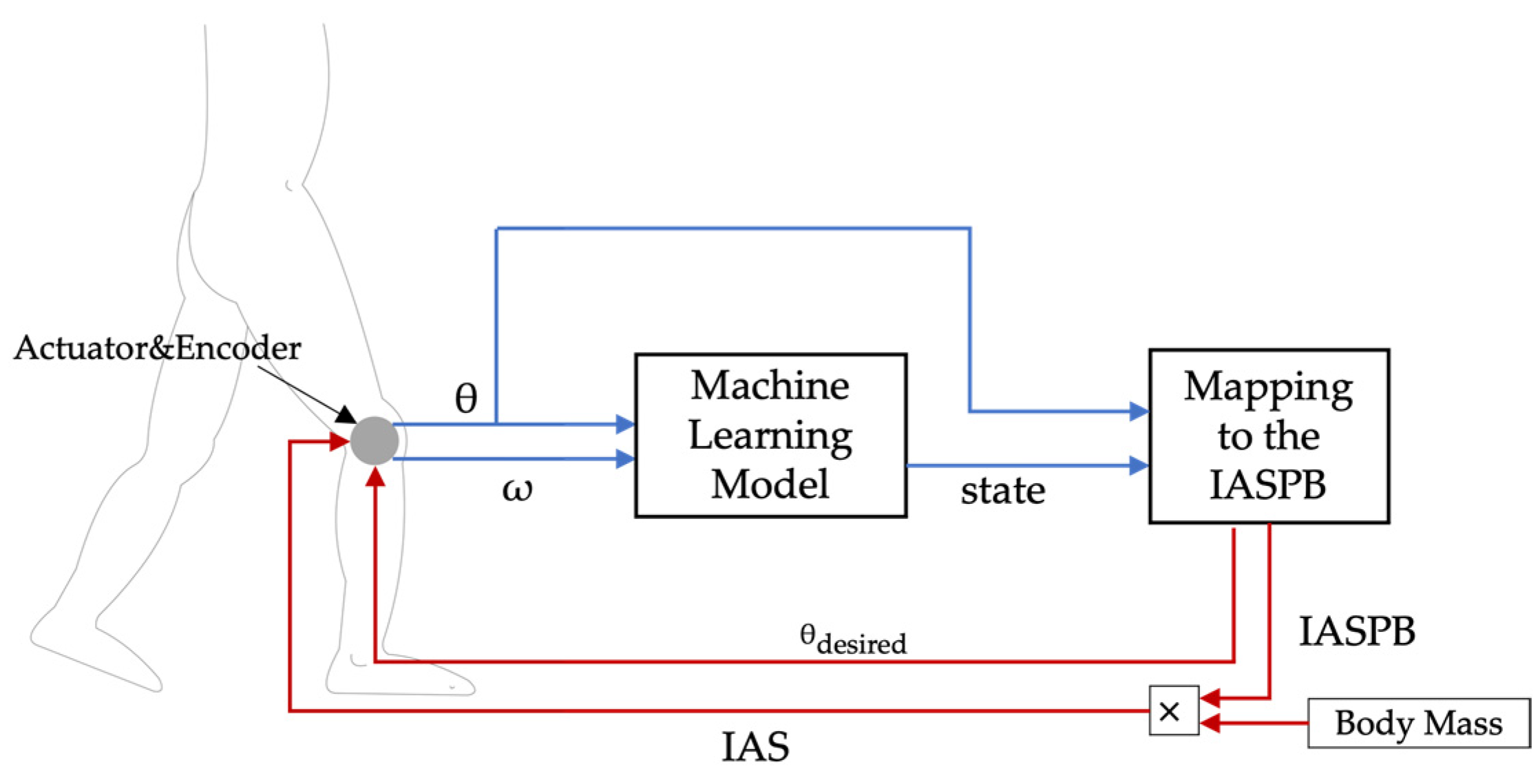
3. Machine Learning and Artificial Stiffness Control Strategy (MLASCS)

The machine learning and artificial stiffness control strategy (MLASCS) is proposed as an alternative strategy to control a knee assistive device in a gait cycle. The advantage of this strategy is that only the knee angle and the knee angular velocity (knee omega) are required to determine the state of a gait cycle and the amount of support moment provided by the device. In order to make sure that the device does not cause any unwanted injury to the wearer, the MLASCS control system should be combined with a possibility checking function for increasing the accuracy of the state predicted, and various stiffness functions for increasing the suitability of the supporting moment. Furthermore, the artificial stiffness with a goal position can generate a moment of direct command. Artificial stiffness is a function that can predict the amount of stiffness required for supporting gait by the knee angle and the state of gait.

3.1. Classification and Training for Machine Learning Model

In a gait cycle, there are two main phases, which are the stance phase and the swing phase, and one knee angle can be in both the swing and stance phases. Therefore, it is necessary to create a machine learning model to classify the walking stage for predicting the walking phase to determine proper knee moment support at any position of a gait cycle.

3.1.1. Classification

As stated above, the position of a gait cycle and a state of walking cannot be determined from just a knee angle, and the second variable that can be used to classify the state is knee omega. As shown in Figure 8, all nine trial data were calculated by Equation (2), post-processed, and plotted to see the relationship between knee angle and knee omega. The inner loop and outer loop cannot be mapped to the swing and stance phases. Therefore, a new set of states in a gait cycle should be invented for further control in this system.
As observed from a gait cycle, the plot could be separated into four states by the local minimum and maximum points in a knee angle for easy classification in a training process. These are initial place, final place, initial lift, and final lift states, where each state position is also shown in Figure 8 and can be mapped to a gait cycle as shown in Figure 9. The initial place starts when the knee is fully extended before the heel touches the ground (omega is more than zero within the inner loop). Then, the final place begins after the knee extends from flexing because of the body weight while being placed on the ground (omega is less than zero within the inner loop). After the foot kicks the ground and starts flexing within the stance phase, the initial lift starts (omega is more than zero). Finally, the final lift is the state when the knee extends for a heel strike in the next gait cycle (omega is less than zero).
In the initial and final place states, the knee angle does not exceed 25 degrees by observation from the gait cycle. The knee omega in the initial place state should be positive and negative for the final place state. The knee omegas of the initial and final lift states have the same characteristics in the initial and final place, but the knee angle can be up to 70 degrees following the recorded data.

3.1.2. Training

After defining the state of all training data, the classification learner of the MATLAB program was used to create a machine learning model. The benefit of a machine learning technique is that the model can classify precisely when there are a lot of training data. In that case, if the model can predict the state correctly with a difference in gait speed, the model is truly helpful. However, the model should predict correctly at least in a specific gait speed before testing with different gait speed training data. This paper focus on data with a gait speed of around 1.5 m/s. The training data was trained with many types of classifiers such as decision trees (accuracy: 80.0–92.5%), discriminant analysis (accuracy: 76.6–77.1%), naïve Bayes classifiers (accuracy: 77.6–81.5%), support vector machines (accuracy: 84.8%–93.7%), and nearest neighbor classifiers (accuracy: 78.8–95.0%). The best accuracy model type of mentioned classifier is the k-nearest neighbor (KNN) with the setting for training shown in Table 1, of which the accuracy is around 95.0%.

3.1.3. Improving

After comparing the predicted state with the testing data, it is found that most of the incorrect predictions are at the intersection point between the initial place and initial lift (see Figure 8) where the exerted moments are much different, so it might be dangerous operating the knee device with this model. Thus, the continuity of state checking (CoSC) is presented to improve prediction accuracy. The CoSC requires the last and current predicted state to confirm the correctness of the prediction. Because walking is a continuous loop posture, all states go in the following order: the initial place, final place, initial lift, final lift, and then it starts a new loop with the initial place state. In order to prevent misclassifying between the initial place and the initial lift, the CoSC was applied to confirm that the initial lift state always follows the initial lift or final place, and the initial place state chases the initial place and final lift only. After predicting the sample data with the machine learning model with the CoSC, the accuracy increased to 99.9%, as seen in the validation confusion matrix of the machine learning model in Figure 10. However, the limitation of this machine learning model is that the model was calculated from the gait data with a gait speed of around 1.5 m/s. The accuracy may decrease if the model were to be used to predict data from another gait speed. Nonetheless, the state of any gait cycle still circulates as the initial place, final place, initial lift, and final lift. Therefore, the CoSC can lead the prediction state result state to follow the loop of states in a gait cycle. Another limitation is the processing time; the fastest prediction speed is around 168 observations per second. Note that the prediction speed can be changed depending on the computer and its processor.

3.2. Artificial Stiffness Control

An artificial stiffness control is an alternative method to support knee moments during a gait cycle. The idea comes from an observation of a torsion spring that can generate a return moment if the spring moves from rest. Therefore, if a controllable actuator is commanded with the desired position, the artificial rest position, and the proportional gain, it can act like a torsion spring with the desired stiffness. Compared to a direct torque-applied method, this method may be more friendly to the user because a supporting moment acts like an elastic spring. If it approaches the desired position, the generated moment should drop and eventually stop as it reaches the desired position.

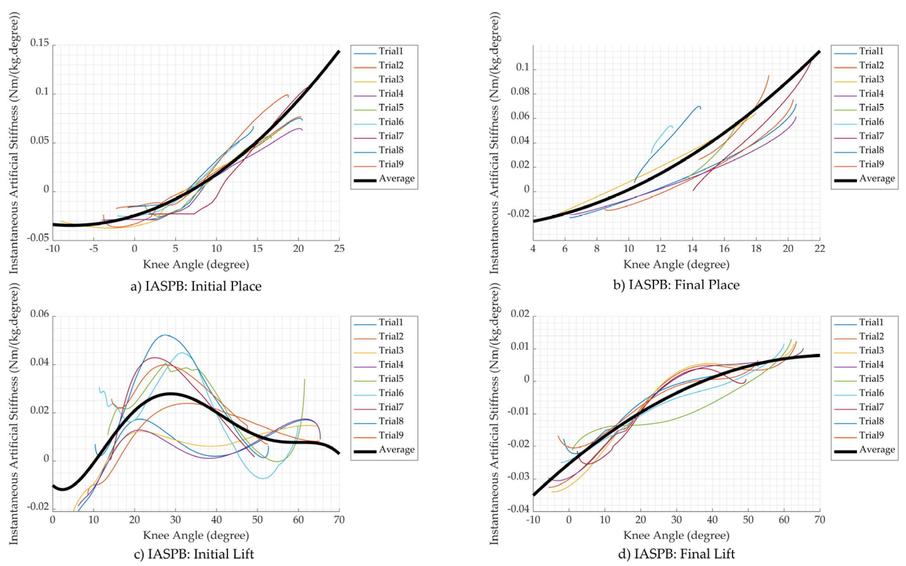
3.2.1. Instantaneous Artificial Stiffness (IAS)

An instantaneous artificial stiffness is estimated from a knee moment (Mknee) and an angle deflection, a constant determinable number that deflects from the knee angle. If the determined deflection angle is low, the IAS will be high, and vice versa, as seen in the following equation of knee moment:
Mknee = IAS × (deflection angle),
Thus, in this case, the deflection was set to 10 degrees because the instantaneous artificial stiffness is not large, and there is enough deflection for commanding an actuator to operate. In general, MPBknee was used instead of the Mknee to estimate an instantaneous artificial stiffness per body mass (IASPB), as seen in the following Equation (12), where i represents the knee angle:
IASPB ( i ) = MPB knee ( i ) 10

3.2.2. Artificial Stiffness Control Equations

Because the gait cycles of different persons may not be the same, it is better to find the equations to estimate the instantaneous artificial stiffness per body mass (IASPB) in a gait cycle, so the equations can be used commonly. The average knee moment per body mass (AMPBknee), calculated from the average of all MPBknee data, was used to obtain IASPB equations in each state by the polyfit function in MATLAB, as shown in Equations (13)–(16). The IASPBIP, IASPBFP, IASPBIL, and IASPBFL are the functions of IASPB in the initial place, final place, initial lift, and final lift state, respectively, where a is the knee angle. Figure 11 shows plots of the IASPB path on knee angle in all trials and the estimated value from the equations in each state, where the positive value means the extension direction and the negative value is the flexion direction.
IASPBIP (a) = 0.0073a2 + 0.0391a + 0.0179
IASPBFP (a) = 0.0023a2 + 0.0237a + 0.0303
IASPBIL (a) = −0.002a5 + 0.0057a4 + 0.0067a3 − 0.026a2 + 0.0019a + 0.0279
IASPBFL (a) = − 0.0028a2 + 0.0111a − 0.003
The concept of artificial stiffness control combined with machine learning is shown in Figure 12. The current knee angle ( θ ) and the current knee omega ( ω ) measured from the encoder were used to predict the current state of a gait cycle by the machine learning model. After that, the current state and θ were used to calculate the current IASPB. The current IASPB was then multiplied by the body mass and the mass of a sample to obtain an instantaneous artificial stiffness (IAS). The actuator required the IAS and the desired position ( θ desired ) to generate the moment for supporting the knee. The θ desired is set to be 10 degrees away from the θ . Finally, the IAS and θ desired were used to command the actuator.

4. Simulation and Validation

This part shows the simulation method to validate the MLASCS concept and also determines the effort over a gait cycle (modified from [31]) for comparing the walking efficiency. The data for testing was from the average knee angle and knee omega of the nine trial data recorded. In the simulation, the supporting moment, which is the moment generated by the actuator for assisting the walking, was estimated by using instantaneous artificial stiffness (IAS) equations. The simulation path was calculated as shown in Figure 12. The sample knee angle and omega predicted the state of gait by the machine learning model. Then, the predicted state and knee angle mapped the amount of IASPB using Equations (13)–(16). Finally, the IASPB was multiplied by the sample mass and predicted the amount of supporting moment by multiplying the IAS with the angle deflection. The validation is carried out by comparing the amount of effort over a gait cycle when applying supporting moments to the amount of effort without the support.

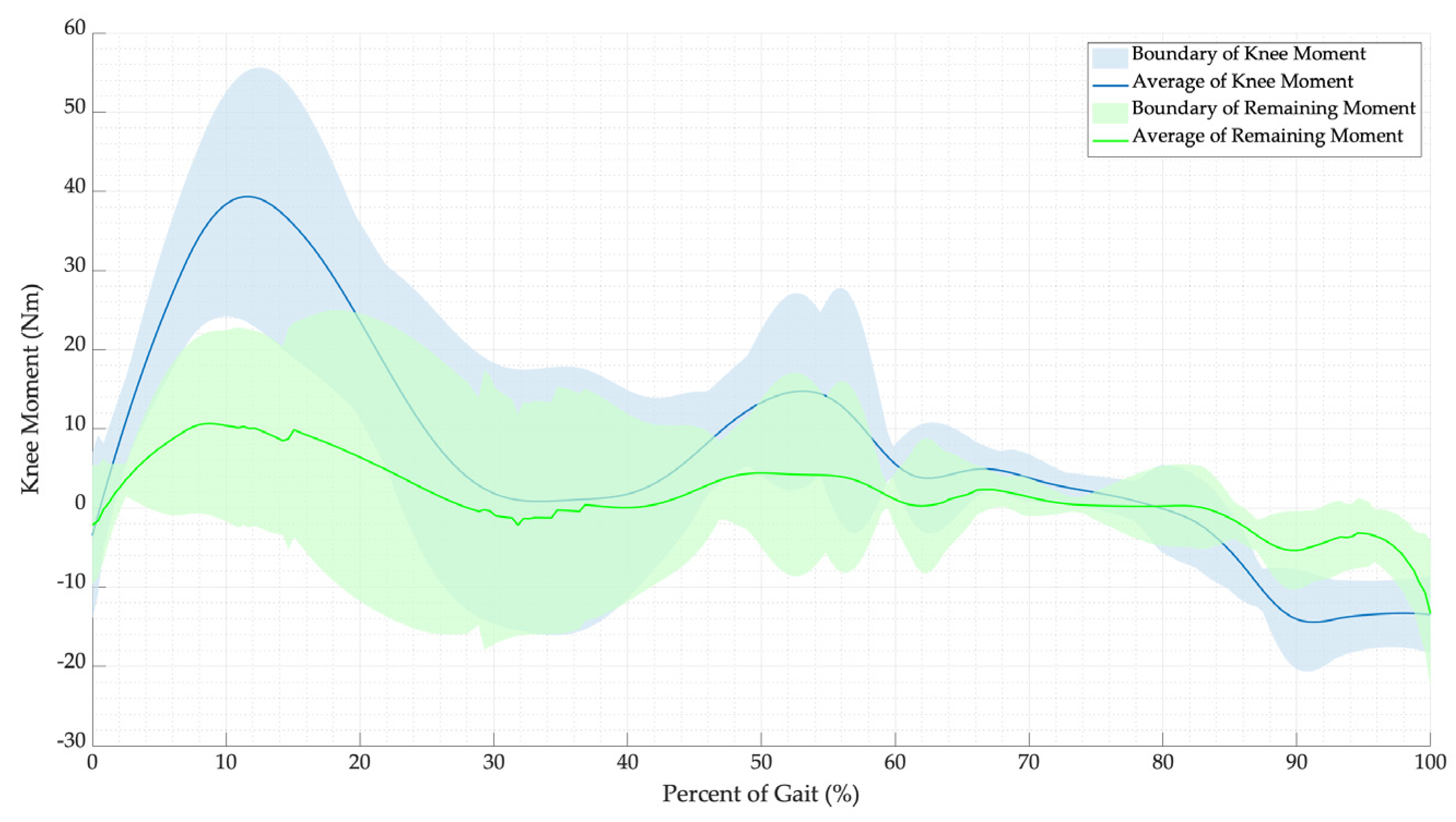
4.1. Supporting Moment Simulation

The simulation settings were chosen to have the test as close to the real system. The knee angle (θ) and the knee omega ( ω ) of the sample were imported one set at a time. Then, this set was used to predict the state and determine the IAS and θ desired . The IAS from the IASPB equations can be either positive or negative, but stiffness in the negative has no meaning. In the case that the IAS is negative, it will be change to positive, and the θ desired will be negative instead. The IAS, θ, and θ desired can be used to estimate the supporting moment (Ms) with an adjustable percentage of support (n), between 0–1, by the following equation:
M s = n | IAS |   ( θ θ desired
Furthermore, Ms was used to calculate the remaining knee moment (Mr), i.e., the moment that is still required for walking after being supported by the device, via the following equation:
Mr = Mknee − Ms.
After simulating with many sets of gait data, it is found that Ms is frequently higher than the exerted moment. As a result, the percentage of support should be reduced. After optimizing the percentage of support to prevent over-assisting moments in all trial data, n should be less than 70% or 0.7. Consequently, all Mknee data were compared to the average and boundary of Mknee when the n is 0.7, as seen in Figure 13.

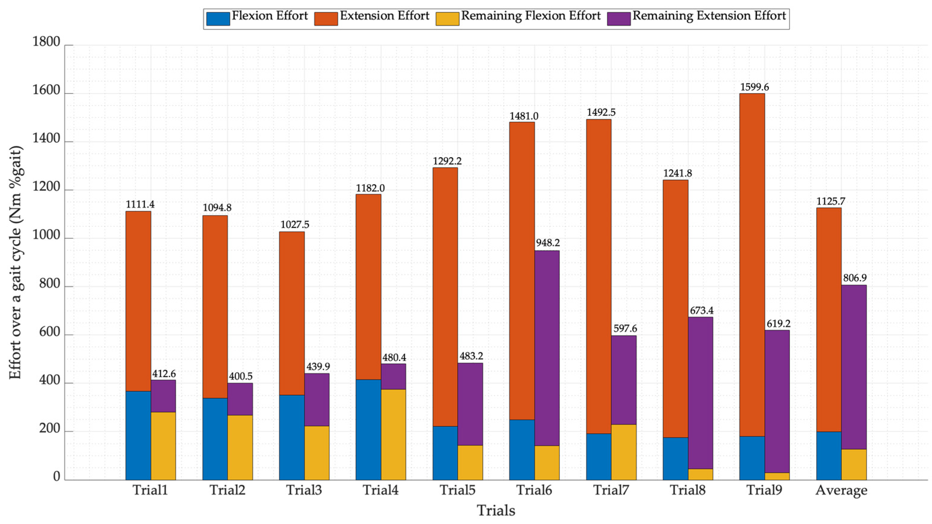
4.2. Effort over a Gait Cycle

An effort over a gait cycle can be used to validate and examine the difference of effort between the sample path and the resulting path obtained from the effort over time presented by Chaichaowarat et al. [31]. The effort over a gait cycle was divided into two parts, namely the extension effort (EE) and the flexion effort (FE). The EE and the FE were determined by integrating the extension moment (EM), i.e., the moment in extension direction, and the flexion moment (FM), i.e., the moment in flexion direction, over a percent of gait (PoG), as in Equations (19) and (20), respectively. Then, the summation of EE and FE is the total effort (TE), as in Equation (21), which is used for comparing the efficiency of the MLASCS. The efforts of each trial, calculated from the measured knee moment, and their remaining efforts, determined from the remaining moments with assistance from the device, are shown in Figure 14.
E E = 0 1 E M d P o G
F E = 0 1 F M d P o G
TE = EE + FE

5. Results and Discussion

Knee assistive devices need knee data to control the device correctly without any harm to the user. The primary information for controlling a knee device is the knee angle and the knee moment. For controlling the walking gait, the secondary set of data required is the phase of gait, as each phase needs a different amount of support. Therefore, the machine learning and artificial stiffness control strategy (MLASCS) was applied to classify the phase of gait: initial place, final place, initial lift, and final lift state. After that, the predicted state and knee angle was used to estimate the amount of support by the instantaneous artificial stiffness per body mass (IASPB) equations mentioned in the above section.
The instantaneous artificial stiffness per body mass (IASPB) equations were separated into four equations, namely IASPBIP, IASPBFP, IASPBIL, and IASPBFL, which are the functions of IASPB in the initial place, final place, initial lift, and final lift state, respectively. Each IASPB function was calculated from the average knee moment per body mass (AMPBknee) so that the supporting moment may exceed or be lower compared to the required knee moment for walking. The percentage of support (n) was invented to adjust the supporting moment. As a result, the n should be 0.7 so that the supporting moment does not exceed the required moment.
In the simulation section, the MLASCS was tested by using all recorded trial data and average data to validate the efficiency of the strategy by using the effort over a gait cycle, as shown in the previous section. The results show that the prediction of the machine learning model is working well. The model mostly predicts the current state correctly, and the IASPB equations can give an amount of stiffness for supporting the knee in each position which is mainly a bit lower than required for walking. The total effort of the recorded data was converted to 100% for easy comparison with their total effort after it was supported in each trial shown, as shown in Table 2.
The total remaining effort, i.e., the effort that is still required for walking after supporting in each trial, showed that this strategy assists knee moments while walking in every trial. The percentage of the remaining effort will change if the percentage of support (n) is adjusted. For example, if the n is too high, the supporting moment will exceed the moment required, so the effort will be larger than the required effort, but if the n is too low, the effort will be close to the required effort which means it does not support enough. As seen in Table 2, the extension effort was highly reduced by the strategy compared to the flexion. In some trials, this strategy reduced the flexion effort by less than 10% or even increased the effort. As a result, it caused an adverse effect on the user. Then, the n should be changed individually depending on the user. Note that if the n is too small, the supporting moment is minimal, and vice versa.
After testing and validating the MLASCS, it seems that the strategy can be used in a knee-assistive device. The technique can predict the amount of supporting moments from the recorded gait data. The MLASCS speed is around 165 observers/s. In a single gait cycle while walking around 1.5 m/s, the time duration is around 1.1 s, so the MLASCS can handle gait data and estimate the amount of supporting moment. The results showed that the walking effort was reduced to 63.4% when the n was 0.7.

6. Conclusions

In a knee assistive device, a control algorithm is one of the most important parts. Depending on the controlling system, the device can operate smoothly or harm a user. This study aims to validate a new type of control strategy called the machine learning and artificial stiffness control strategy (MLASCS) for commanding the proper amount of support moment to assist while walking. The MLASCS is composed of a trained machine learning model and the instantaneous artificial stiffness per body mass (IASPB) equations. The trained model can classify the state of a gait cycle by using knee angle and omega. The accuracy of the modified machine learning model is around 99.9%. The IASPB equations require the knee angle and the state to map the amount of stiffness to support the knee moment. The support moment will change if the user adjusts the percentage of support (n), so the user can select the amount of assistance. After validating the MLASCS with nine trial data sets, the strategy can reduce the total effort over a gait cycle up to 63.4% when the n was 0.7. The extension effort was mainly reduced, so for those who want to combine this strategy with the knee assistive device, the posterior support device is recommended. The authors highly recommend a device that is designed for supporting extension direction instead of flexion direction because of the high extension moment required for walking. Moreover, the knee joint of a knee device might not align with the human knee joint, so the machine learning model should be retrained following the joint angle while walking. Because there are many variables in this article, Table 3 summarizes important variables in this paper for a better understanding.

Author Contributions

Conceptualization, K.P. and N.A.; methodology, K.P. and N.A.; software, K.P.; validation, K.P.; formal analysis, K.P.; investigation, K.P.; resources, K.P. and N.A.; data curation, K.P.; writing—original draft preparation, K.P.; writing—review and editing, N.A.; visualization, K.P.; supervision, N.A.; project administration, K.P. and N.A.; funding acquisition, K.P. and N.A. All authors have read and agreed to the published version of the manuscript.

Funding

This research received no external funding.

Institutional Review Board Statement

Not applicable.

Informed Consent Statement

Informed consent was obtained from all subjects involved in the study.

Conflicts of Interest

The authors declare no conflict of interest.

References

  1. O’Connor, J.J.; Shercliff, T.L.; Biden, E.; Goodfellow, J.W. The Geometry of the Knee in the Sagittal Plane. Proc. Inst. Mech. Eng. Part H J. Eng. Med. 1989, 203, 223–233. [Google Scholar] [CrossRef] [PubMed]
  2. Forner-Cordero, A.; Pons, J.L.; Turowska, E.A.; Schiele, A. Kinematics and dynamics of wearable robots. In Wearable Robots: Biomechatronic Exoskeletons; Wiley: Hoboken, NJ, USA, 2008; pp. 47–85. [Google Scholar]
  3. Maeda, D.; Tominaga, K.; Oku, T.; Pham, H.T.T.; Saeki, S.; Uemura, M.; Hirai, H.; Miyazaki, F. Muscle synergy analysis of human adaptation to a variable-stiffness exoskeleton: Human walk with a knee exoskeleton with pneumatic artificial muscles. In Proceedings of the 2012 12th IEEE-RAS International Conference on Humanoid Robots (Humanoids 2012), Osaka, Japan, 29 November–1 December 2012. [Google Scholar]
  4. Zhu, J.; Wang, Y.; Jiang, J.; Sun, B.; Cao, H. Unidirectional variable stiffness hydraulic actuator for load-carrying knee exoskeleton. Int. J. Adv. Robot. Syst. 2017, 14, 1729881416686955. [Google Scholar] [CrossRef] [Green Version]
  5. Anam, K.; Al-Jumaily, A.A. Active exoskeleton control systems: State of the art. Procedia Eng. 2012, 41, 988–994. [Google Scholar] [CrossRef] [Green Version]
  6. Zhang, L.; Liu, G.; Han, B.; Wang, Z.; Li, H.; Jiao, Y. Assistive devices of human knee joint: A review. Robot. Auton. Syst. 2020, 125, 103394. [Google Scholar] [CrossRef]
  7. Ergin, M.A.; Patoglu, V. A self-adjusting knee exoskeleton for robot-assisted treatment of knee injuries. In Proceedings of the 2011 IEEE/RSJ International Conference on Intelligent Robots and Systems, San Francisco, CA, USA, 25–30 September 2011; pp. 4917–4922. [Google Scholar]
  8. Khamar, M.; Edrisi, M. Designing a backstepping sliding mode controller for an assistant human knee exoskeleton based on nonlinear disturbance observer. Mechatronics 2018, 54, 121–132. [Google Scholar] [CrossRef]
  9. Mazumder, O.; Kundu, A.S.; Chattaraj, R.; Lenka, P.K.; Gupta, K.; Bhaumik, S. Development of series elastic actuator based myoelectric knee exoskeleton for trajectory generation and load augmentation. In Proceedings of the Conference on Advances in Robotics ACM 2015, Goa, India, 2–4 July 2015; pp. 1–6. [Google Scholar]
  10. Dos Santos, W.M.; Caurin, G.A.; Siqueira, A.A. Design and control of an active knee orthosis driven by a rotary series elastic actuator. Control. Eng. Pract. 2017, 58, 307–318. [Google Scholar] [CrossRef]
  11. Han, Y.; Zhu, S.; Zhou, Z.; Shi, Y.; Hao, D. Research on a multimodal actuator-oriented power-assisted knee exoskeleton. Robotica 2017, 35, 1906–1922. [Google Scholar] [CrossRef]
  12. Han, Y.; Qi, B.; Yu, J. Development and experimental study of elastic actuator for a power-assisted knee exoskeleton. Robot 2014, 36, 668–675. [Google Scholar]
  13. Han, Y.; Wu, Z.; Xu, Y.; Wen, X.; Zhu, S.; Hao, D. The Knee Exoskeleton Mechanical Leg Based on Multi-modal Elastic Actuator. Jiqiren/Robot. 2017, 39, 498–504. [Google Scholar] [CrossRef]
  14. Yali, H.; Dabin, H.; Yu, S.; Songqing, Z.; Zhou, Z. The energy amplification characteristic research of a multimodal actuator. Int. J. Adv. Robot. Syst. 2016, 13, 93. [Google Scholar] [CrossRef] [Green Version]
  15. Félix, P.; Figueiredo, J.; Santos, C.P.; Moreno, J.C. Powered knee orthosis for human gait rehabilitation: First advances. In Proceedings of the 2017 IEEE 5th Portuguese Meeting on Bioengineering (ENBENG), Coimbra, Portugal, 16–18 February 2017. [Google Scholar]
  16. Figueiredo, J.; Félix, P.; Santos, C.P.; Moreno, J.C. Towards human-knee orthosis interaction based on adaptive impedance control through stiffness adjustment. In Proceedings of the IEEE International Conference on Rehabilitation Robotics, London, UK, 17–20 July 2017. [Google Scholar]
  17. Nikitczuk, J.; Das, A.; Vyas, H.; Weinberg, B.; Mavroidis, C. Adaptive torque control of electro-rheological fluid brakes used in active knee rehabilitation devices. In Proceedings of the IEEE International Conference on Robotics and Automation, Orlando, FL, USA, 15–19 May 2006. [Google Scholar]
  18. Weinberg, B.; Nikitczuk, J.; Patel, S.; Patritti, B.; Mavroidis, C.; Bonato, P.; Canavan, P. Design, control and human testing of an active knee rehabilitation orthotic device. In Proceedings of the IEEE International Conference on Robotics and Automation, Rome, Italy, 10–14 April 2007. [Google Scholar]
  19. Jiang, J.; Zhang, Z.; Wang, Z.; Qian, J. Study on real-time control of exoskeleton knee using electromyographic signal. In Proceedings of the Life System Modeling and Intelligent Computing: International Conference on Life System Modeling and Simulation, LSMS 2010, and International Conference on Intelligent Computing for Sustainable Energy and Environment, ICSEE 2010, Wuxi, China, 17–20 September 2010; Springer: Berlin/Heidelberg, Germany, 2010. [Google Scholar]
  20. Shan, H.; Jiang, C.; Mao, Y.; Wang, X. Design and control of a wearable active knee orthosis for walking assistance. In Proceedings of the 2016 IEEE 14th International Workshop on Advanced Motion Control (AMC), Auckland, New Zealand, 22–24 April 2016; IEEE: Piscataway, NJ, USA, 2016. [Google Scholar]
  21. el Zahraa Wehbi, F.; Huo, W.; Amirat, Y.; El Rafei, M.; Khalil, M.; Mohammed, S. Active impedance control of a knee-joint orthosis during swing phase. In Proceedings of the 2017 International Conference on Rehabilitation Robotics (ICORR), London, UK, 17–20 July 2017; IEEE: Piscataway, NJ, USA, 2017. [Google Scholar]
  22. Huang, T.-H.; Huang, H.P.; Cheng, C.-A.; Kuan, J.-Y.; Lee, P.-T.; Huang, S.-Y. Design of a new hybrid control and knee orthosis for human walking and rehabilitation. In Proceedings of the 2012 IEEE/RSJ International Conference on Intelligent Robots and Systems, Vilamoura-Algarve, Portugal, 7–12 October 2012; IEEE: Piscataway, NJ, USA, 2012. [Google Scholar]
  23. Liu, L.; Lüken, M.; Leonhardt, S.; Misgeld, B.J.E. EMG-driven model-based knee torque estimation on a variable impedance actuator orthosis. In Proceedings of the 2017 IEEE International Conference on Cyborg and Bionic Systems (CBS), Beijing, China, 17–19 October 2017. [Google Scholar]
  24. Rogers, E.; Polygerinos, P.; Allen, S.; Panizzolo, F.A.; Walsh, C.J.; Holland, D.P. A quasi-passive knee exoskeleton to assist during descent. In Wearable Robotics: Challenges and Trends, Proceedings of the 2nd International Symposium on Wearable Robotics, WeRob2016, Segovia, Spain, 18–21 October 2016; Springer: Berlin/Heidelberg, Germany, 2016. [Google Scholar]
  25. Shamaei, K.; Cenciarini, M.; Adams, A.A.; Gregorczyk, K.N.; Schiffman, J.M.; Dollar, A.M. Design and evaluation of a quasi-passive knee exoskeleton for investigation of motor adaptation in lower extremity joints. IEEE Trans. Biomed. Eng. 2014, 61, 1809–1821. [Google Scholar] [CrossRef] [PubMed]
  26. Shamaei, K.; Napolitano, P.C.; Dollar, A.M. A quasi-passive compliant stance control Knee-Ankle-Foot Orthosis. In Proceedings of the IEEE International Conference on Rehabilitation Robotics, Seattle, WA, USA, 24–26 June 2013. [Google Scholar]
  27. Yuan, B.; Li, B.; Chen, Y.; Tan, B.; Jiang, M.; Tang, S.; Wei, Y.; Wang, Z.; Ma, B.; Huang, J. Designing of a passive knee-assisting exoskeleton for weight-bearing. Proccedings of the 10th International Conference, Intelligent Robotics and Applications, ICIRA 2017, Wuhan, China, 16–18 August 2017; Part II 10. Springer: Berlin/Heidelberg, Germany, 2017. [Google Scholar]
  28. Saleem, A.; Khan, M.R.; Ahmmad, S.M. A novel knee exoskeleton for overweight person. In Proceedings of the 2015 10th Asian Control Conference (ASCC), Sabah, Malaysia, 31 May–3 June 2015. [Google Scholar]
  29. Wu, S.-L.; Kazerooni, H. Design of a passive exoskeleton knee to assist toe clearance. In Proceedings of the Dynamic Systems and Control Conference 2017, Tysons, VA, USA, 11–13 October 2017; American Society of Mechanical Engineers: New York, NY, USA, 2017. [Google Scholar]
  30. Chandrapal, M.; Chen, X.; Wang, W. Intelligent Assistive Knee Exoskeleton. In Mechatronics; Wiley: Hoboken, NJ, USA, 2013; pp. 195–237. [Google Scholar]
  31. Chaichaowarat, R.; Granados, D.F.P.; Kinugawa, J.; Kosuge, K. Passive knee exoskeleton using torsion spring for cycling assistance. In Proceedings of the 2017 IEEE/RSJ International Conference on Intelligent Robots and Systems (IROS), Vancouver, BC, Canada, 24–28 September 2017; IEEE: Piscataway, NJ, USA, 2017. [Google Scholar]
  32. Chaichaowarat, R.; Kinugawa, J.; Kosuge, K. Unpowered Knee Exoskeleton Reduces Quadriceps Activity during Cycling. Engineering 2018, 4, 471–478. [Google Scholar] [CrossRef]
  33. Ranaweera, R.; Gopura, R.; Jayawardena, T.; Mann, G.K. Development of A Passively Powered Knee Exoskeleton for Squat Lifting. J. Robot. Netw. Artif. Life 2018, 5, 45–51. [Google Scholar] [CrossRef] [Green Version]
  34. Moyer, R.; Birmingham, T.; Dombroski, C.; Walsh, R.; Giffin, J.R. Combined versus individual effects of a valgus knee brace and lateral wedge foot orthotic during stair use in patients with knee osteoarthritis. Gait Posture 2017, 54, 160–166. [Google Scholar] [CrossRef] [PubMed]
  35. Kim, J.-H.; Shim, M.; Ahn, D.H.; Son, B.J.; Kim, S.-Y.; Kim, D.Y.; Baek, Y.S.; Cho, B.-K. Design of a knee exoskeleton using foot pressure and knee torque sensors. Int. J. Adv. Robot. Syst. 2015, 12, 112. [Google Scholar] [CrossRef]
  36. Celebi, B.; Yalcin, M.; Patoglu, V. AssistOn-Knee: A self-aligning knee exoskeleton. In Proceedings of the IEEE International Conference on Intelligent Robots and Systems, Tokyo, Japan, 3–7 November 2013. [Google Scholar]
  37. Wang, J.; Li, X.; Huang, T.H.; Yu, S.; Li, Y.; Chen, T.; Carriero, A.; Oh-Park, M.; Su, H. Comfort-Centered Design of a Lightweight and Backdrivable Knee Exoskeleton. IEEE Robot. Autom. Lett. 2018, 3, 4265–4272. [Google Scholar] [CrossRef]
  38. Luo, Y.; Wang, C.; Wang, Z.; Ma, Y.; Wang, C.; Wu, X. Design and control for a compliant knee exoskeleton. In Proceedings of the 2017 IEEE International Conference on Information and Automation, ICIA 2017, Macao, China, 18–20 July 2017. [Google Scholar]
  39. Shepherd, M.K.; Rouse, E.J. Design and Validation of a Torque-Controllable Knee Exoskeleton for Sit-to-Stand Assistance. IEEE/ASME Trans. Mechatron. 2017, 22, 1695–1704. [Google Scholar] [CrossRef]
  40. Karavas, N.; Ajoudani, A.; Tsagarakis, N.; Saglia, J.; Bicchi, A.; Caldwell, D. Tele-impedance based assistive control for a compliant knee exoskeleton. Robot. Auton. Syst. 2015, 73, 78–90. [Google Scholar] [CrossRef]
  41. Karavas, N.C.; Tsagarakis, N.G.; Caldwell, D.G. Design, modeling and control of a series elastic actuator for an assistive knee exoskeleton. In Proceedings of the 2012 4th IEEE RAS & EMBS International Conference on Biomedical Robotics and Biomechatronics (BioRob), Rome, Italy, 24–27 June 2012. [Google Scholar]
  42. Karavas, N.C.; Tsagarakis, N.G.; Saglia, J.; Galdwell, D.G. A novel actuator with reconfigurable stiffness for a knee exoskeleton: Design and modeling. In Advances in Reconfigurable Mechanisms and Robots I; Springer: Berlin/Heidelberg, Germany, 2012; pp. 411–421. [Google Scholar]
  43. Lerner, Z.F.; Damiano, D.L.; Bulea, T.C. A lower-extremity exoskeleton improves knee extension in children with crouch gait from cerebral palsy. Sci. Transl. Med. 2017, 9, eaam9145. [Google Scholar] [CrossRef] [Green Version]
  44. Lerner, Z.F.; Damiano, D.L.; Park, H.S.; Gravunder, A.J.; Bulea, T.C. A Robotic Exoskeleton for Treatment of Crouch Gait in Children with Cerebral Palsy: Design and Initial Application. IEEE Trans. Neural Syst. Rehabil. Eng. 2017, 25, 650–659. [Google Scholar] [CrossRef]
  45. Rifaï, H.; Mohammed, S.; Hassani, W.; Amirat, Y. Nested saturation based control of an actuated knee joint orthosis. Mechatronics 2013, 23, 1141–1149. [Google Scholar] [CrossRef]
  46. Rifai, H.; Mohammed, S.; Djouani, K.; Amirat, Y. Toward Lower Limbs Functional Rehabilitation Through a Knee-Joint Exoskeleton. IEEE Trans. Control. Syst. Technol. 2017, 25, 712–719. [Google Scholar] [CrossRef]
  47. Beyl, P.; Knaepen, K.; Duerinck, S.; Van Damme, M.; Vanderborght, B.; Meeusen, R.; Lefeber, D. Safe and compliant guidance by a powered knee exoskeleton for robot-assisted rehabilitation of gait. Adv. Robot. 2011, 25, 513–535. [Google Scholar] [CrossRef]
  48. Knaepen, K.; Beyl, P.; Duerinck, S.; Hagman, F.; Lefeber, D.; Meeusen, R. Human-robot interaction: Kinematics and muscle activity inside a powered compliant knee exoskeleton. IEEE Trans. Neural Syst. Rehabil. Eng. 2014, 22, 1128–1137. [Google Scholar] [CrossRef]
  49. Tung, W.; Kazerooni, H.; Hyun, D.J.; McKinley, S. On the design and control of exoskeleton knee. In Proceedings of the Dynamic Systems and Control Conference, Palo Alto, CA, USA, 21–23 October 2013; American Society of Mechanical Engineers: New York, NY, USA, 2013. [Google Scholar]
  50. Elliott, G.A. Design and evaluation of a quasi-passive robotic knee brace: On the effects of parallel elasticity on human running. Appl. Adv. Technol. Transp. Eng. 2012, 75, 341–345. [Google Scholar]
  51. Elliott, G.; Marecki, A.; Herr, H. Design of a clutch-spring knee exoskeleton for running. J. Med. Devices Trans. ASME 2014, 8, 031002. [Google Scholar] [CrossRef] [Green Version]
  52. Elliott, G.; Sawicki, G.S.; Marecki, A.; Herr, H. The biomechanics and energetics of human running using an elastic knee exoskeleton. In Proceedings of the IEEE International Conference on Rehabilitation Robotics, Seattle, WA, USA, 24–26 June 2013. [Google Scholar]
  53. Pagani, C.H.F.; Potthast, W.; Brüggemann, G.-P. The effect of valgus bracing on the knee adduction moment during gait and running in male subjects with varus alignment. Clin. Biomech. 2010, 25, 70–76. [Google Scholar] [CrossRef]
  54. Pagani, C.H.F.; Willwacher, S.; Kleis, B.; Brüggemann, G.-P. Influence of a valgus knee brace on muscle activation and co-contraction in patients with medial knee osteoarthritis. J. Electromyogr. Kinesiol. 2013, 23, 490–500. [Google Scholar] [CrossRef]
  55. Dollar, A.M.; Herr, H. Design of a quasi-passive knee exoskeleton to assist running. In Proceedings of the 2008 IEEE/RSJ International Conference on Intelligent Robots and Systems, Nice, France, 22–26 September 2008; IEEE: Piscataway, NJ, USA, 2008. [Google Scholar]
  56. Tucker, M.R.; Moser, A.; Lambercy, O.; Sulzer, J.; Gassert, R. Design of a wearable perturbator for human knee impedance estimation during gait. In Proceedings of the 2013 IEEE 13th International Conference on Rehabilitation Robotics (ICORR), Seattle, WA, USA, 24–26 June 2013; IEEE: Piscataway, NJ, USA, 2013. [Google Scholar]
  57. Winter, D.A. Biomechanics and Motor Control of Human Movement; John Wiley & Sons: Hoboken, NJ, USA, 2009. [Google Scholar]
  58. Karavas, N.; Ajoudani, A.; Tsagarakis, N.; Saglia, J.; Bicchi, A.; Caldwell, D. Tele-impedance based stiffness and motion augmentation for a knee exoskeleton device. In Proceedings of the 2013 IEEE International Conference on Robotics and Automation, Karlsruhe, Germany, 6–10 May 2013; IEEE: Piscataway, NJ, USA, 2013. [Google Scholar]
  59. Saccares, L.; Brygo, A.; Sarakoglou, I.; Tsagarakis, N.G. A novel human effort estimation method for knee assistive exoskeletons. In Proceedings of the IEEE International Conference on Rehabilitation Robotics, London, UK, 17–20 July 2017. [Google Scholar]
  60. Saccares, L.; Sarakoglou, I.; Tsagarakis, N.G. iT-Knee: An exoskeleton with ideal torque transmission interface for ergonomic power augmentation. In Proceedings of the 2016 IEEE/RSJ International Conference on Intelligent Robots and Systems (IROS), Daejeon, Republic of Korea, 9–14 October 2016. [Google Scholar]
  61. Zhou, Z.; Liao, Y.; Wang, C.; Wang, Q. Preliminary evaluation of gait assistance during treadmill walking with a light-weight bionic knee exoskeleton. In Proceedings of the 2016 IEEE International Conference on Robotics and Biomimetics (ROBIO), Qingdao, China, 3–7 December 2016. [Google Scholar]
  62. Kamali, K.; Akbari, A.A.; Akbarzadeh, A. Implementation of a trajectory predictor and an exponential sliding mode controller on a knee exoskeleton robot. Modares Mech. Eng. 2016, 16, 79–90. [Google Scholar]
  63. Kardan, I.; Akbarzadeh, A. Robust output feedback assistive control of a compliantly actuated knee exoskeleton. Robot. Auton. Syst. 2017, 98, 15–29. [Google Scholar] [CrossRef]
  64. Kardan, I.; Akbarzadeh, A. Assistive control of a compliantly actuated single axis stage. In Proceedings of the 4th RSI International Conference on Robotics and Mechatronics, ICRoM 2016, Tehran, Iran, 26–28 October 2016. [Google Scholar]
  65. Witte, K.A.; Fatschel, A.M.; Collins, S.H. Design of a lightweight, tethered, torque-controlled knee exoskeleton. In Proceedings of the IEEE International Conference on Rehabilitation Robotics, London, UK, 17–20 July 2017. [Google Scholar]
  66. Sridar, S.; Nguyen, P.H.; Zhu, M.; Lam, Q.P.; Polygerinos, P. Development of a soft-inflatable exosuit for knee rehabilitation. In Proceedings of the 2017 IEEE/RSJ International Conference on Intelligent Robots and Systems (IROS), Vancouver, BC, Canada, 24–28 September 2017. [Google Scholar]
  67. Liao, Y.; Zhou, Z.; Wang, Q. BioKEX: A bionic knee exoskeleton with proxy-based sliding mode control. In Proceedings of the 2015 IEEE International Conference on Industrial Technology (Icit), Seville, Spain, 17–19 March 2015. [Google Scholar]
  68. Li, B.; Yuan, B.; Tang, S.; Mao, Y.; Zhang, D.; Huang, C.; Tan, B. Biomechanical design analysis and experiments evaluation of a passive knee-assisting exoskeleton for weight-climbing. Ind. Robot. Int. J. 2018, 45, 436–445. [Google Scholar] [CrossRef]
  69. Jun, S.; Zhou, X.; Ramsey, D.K.; Krovi, V.N. Compliant knee exoskeleton design: Parallel coupled compliant plate (PCCP) mechanism and pennate elastic band (PEB) spring. In Proceedings of the International Design Engineering Technical Conferences and Computers and Information in Engineering Conference, Buffalo, NY, USA, 17–20 August 2014; American Society of Mechanical Engineers: New York, NY, USA, 2014. [Google Scholar]
  70. Chen, B.; Zi, B.; Wang, Z.; Qin, L.; Liao, W.-H. Knee exoskeletons for gait rehabilitation and human performance augmentation: A state-of-the-art. Mech. Mach. Theory 2019, 134, 499–511. [Google Scholar] [CrossRef]
  71. Malcolm, P.; Galle, S.; Derave, W.; De Clercq, D. Bi-articular knee-ankle-foot exoskeleton produces higher metabolic cost reduction than weight-matched mono-articular exoskeleton. Front. Neurosci. 2018, 12, 69. [Google Scholar] [CrossRef] [PubMed] [Green Version]
  72. Kong, K.; Bae, J.; Tomizuka, M. A compact rotary series elastic actuator for human assistive systems. IEEE/ASME Trans. Mechatron. 2011, 17, 288–297. [Google Scholar] [CrossRef]
  73. Pratt, J.E.; Krupp, B.T.; Morse, C.J.; Collins, S.H. The RoboKnee: An exoskeleton for enhancing strength and endurance during walking. In Proceedings of the IEEE International Conference on Robotics and Automation, New Orleans, LA, USA, 26 April–1 May 2004; IEEE: Piscataway, NJ, USA, 2004. [Google Scholar]
  74. Ma, H.; Lai, W.-Y.; Liao, W.-H.; Fong, D.T.-P.; Chan, K.-M. Design and control of a powered knee orthosis for gait assistance. In Proceedings of the 2013 IEEE/ASME International Conference on Advanced Intelligent Mechatronics, Wollongong, NSW, Australia, 9–12 July 2013; IEEE: Piscataway, NJ, USA, 2013. [Google Scholar]
  75. Ma, H.; Chen, B.; Qin, L.; Liao, W.-H. Design and testing of a regenerative magnetorheological actuator for assistive knee braces. Smart Mater. Struct. 2017, 26, 035013. [Google Scholar] [CrossRef]
  76. Masouros, S.D.; Bull, A.M.J.; Amis, A.A. (i) Biomechanics of the knee joint. Orthop. Trauma 2010, 24, 84–91. [Google Scholar] [CrossRef]
  77. Dixit, S.; Difiori, J.P.; Burton, M.; Mines, B. Management of patellofemoral pain syndrome. Am. Fam. Physician 2007, 75, 194–202. [Google Scholar] [PubMed]
  78. Bertomeu, J.M.B.; Lois, J.M.B.; Guillem, R.B.; Del Pozo, Á.P.; Lacuesta, J.; Mollà, C.G.; Luna, P.V.; Pastor, J.P. Development of a hinge compatible with the kinematics of the knee joint. Prosthet. Orthot. Int. 2007, 31, 371–383. [Google Scholar] [CrossRef] [Green Version]
  79. Rose, J.; Gamble, J.G. Human Walking; Lippincott Williams & Wilkins: Philadelphia, PA, USA, 2006. [Google Scholar]
  80. Grimmer, M.; Schmidt, K.; Duarte, J.E.; Neuner, L.; Koginov, G.; Riener, R. Stance and swing detection based on the angular velocity of lower limb segments during walking. Front. Neurorobotics 2019, 13, 57. [Google Scholar] [CrossRef] [PubMed] [Green Version]
  81. Javanfar, A.; Bamdad, M. A developed multibody knee model for unloading knee with cartilage penetration depth control. Proc. Inst. Mech. Eng. Part H J. Eng. Med. 2022, 236, 1528–1540. [Google Scholar] [CrossRef]
  82. Mokri, C.; Bamdad, M.; Abolghasemi, V. Muscle force estimation from lower limb EMG signals using novel optimised machine learning techniques. Med. Biol. Eng. Comput. 2022, 60, 683–699. [Google Scholar] [CrossRef] [PubMed]
  83. Rattanasak, A.; Uthansakul, P.; Uthansakul, M.; Jumphoo, T.; Phapatanaburi, K.; Sindhupakorn, B.; Rooppakhun, S. Real-Time Gait Phase Detection Using Wearable Sensors for Transtibial Prosthesis Based on a kNN Algorithm. Sensors 2022, 22, 4242. [Google Scholar] [CrossRef] [PubMed]
  84. Chen, B.; Chen, C.; Hu, J.; Sayeed, Z.; Qi, J.; Darwiche, H.F.; Little, B.E.; Lou, S.; Darwish, M.; Foote, C. Computer Vision and Machine Learning-Based Gait Pattern Recognition for Flat Fall Prediction. Sensors 2022, 22, 7960. [Google Scholar] [CrossRef] [PubMed]
  85. Robertson, D.; Caldwell, G.; Hamill, J.; Kamen, G.; Whittlesey, S. Research Methods in Biomechanics, 2nd ed.; Human Kinetics: Boston, MA, USA, 2013. [Google Scholar]
  86. Quarteroni, A.; Saleri, F.; Gervasio, P. Scientific Computing with MATLAB and Octave; Springer: Berlin/Heidelberg, Germany, 2006; Volume 3. [Google Scholar]
  87. Fornberg, B. Generation of finite difference formulas on arbitrarily spaced grids. Math. Comput. 1988, 51, 699–706. [Google Scholar] [CrossRef]
Figure 1. Human gait cycle (modified from [70,79]).
Robotics 12 00044 g001
Figure 2. Human knee joint angle (a) and moment per body mass (b) in a gait cycle.
Robotics 12 00044 g002
Figure 3. Positions of markers for collecting data from the Qualisys motion capture system.
Robotics 12 00044 g003
Figure 4. The experiment room consists of 8 marker detectors, 2 force plates, and 1 camera and the origin and axis of the tests (a), and the position of the marker on the participant (b).
Robotics 12 00044 g004
Figure 5. The average and the boundary of the maximum and minimum of all post-processed data in (a) the knee angle and (b) the knee angular velocity (knee omega).
Robotics 12 00044 g005
Figure 6. The free body diagrams of the lower leg and the foot for calculating the knee moment.
Robotics 12 00044 g006
Figure 7. The average and the boundary of the knee moment per body mass from the calculations.
Robotics 12 00044 g007
Figure 8. The plot of the nine trial knee angle from post-processed recorded data and knee omega from post-processed and calculated recorded data by Equation (2); the plot can be separated into initial place, final place, initial lift, and final lift states.
Robotics 12 00044 g008
Figure 9. Knee angle and states of a gait cycle.
Robotics 12 00044 g009
Figure 10. The validation confusion matrix of the machine learning model.
Robotics 12 00044 g010
Figure 11. The instantaneous artificial stiffness per body mass (IASPB) path on the knee angle in (a) the initial place state; (b) the final place state; (c) the initial lift state; (d) the final lift state.
Robotics 12 00044 g011
Figure 12. The concept of artificial stiffness control combined with machine learning.
Robotics 12 00044 g012
Figure 13. Plots of the average and boundary of knee moment (Mknee) and remaining knee moment (Mr), i.e., the moment that is still required for walking after being supported by the device when the percentage of support (n) is 0.7.
Robotics 12 00044 g013
Figure 14. Comparison of the effort over a gait cycle from recorded walking data and remaining effort over a gait cycle in each trial. Note that the numbers shown at the top of the bars are the total effort of each bar.
Robotics 12 00044 g014
Table 1. The settings for training the KNN machine learning model.
SettingDetail
PresetFine KNN
Number of neighbors3
Distance metricChebyshev
Distance weightEqual
Standardize dataTrue
Table 2. Comparison of the effort over a gait cycle from the recorded data and remaining moment.
TrialsDataFlexion Effort (FE)Extension Effort (EE)Total Effort (TE)Reduction
Trial 1Effort without assist33.0%67.0%100%62.9%
Remaining effort25.2%11.9%37.1%
Trial 2Effort without assist30.9%69.1%100%63.4%
Remaining effort24.4%12.2%36.6%
Trial 3Effort without assist34.2%65.8%100%57.2%
Remaining effort21.8%21.0%42.8%
Trial 4Effort without assist35.1%64.9%100%59.4%
Remaining effort31.7%8.9%40.6%
Trial 5Effort without assist17.1%82.9%100%62.6%
Remaining effort11.0%26.4%37.4%
Trial 6Effort without assist16.8%83.2%100%36%
Remaining effort9.6%54.4%64.0%
Trial 7Effort without assist12.8%87.2%100%60%
Remaining effort15.3%24.7%40.0%
Trial 8Effort without assist14.1%85.9%100%45.8%
Remaining effort3.6%50.6%54.2%
Trial 9Effort without assist11.3%88.7%100%61.3%
Remaining effort1.8%36.9%38.7%
AverageEffort without assist17.7%82.3%100%28.3%
Remaining effort11.3%60.3%71.7%
Table 3. Variables table.
CategoryVariable NameAxisVariable
Symbol
Unit
ForceGround reaction forcexGRFxN
zGRFzN
Ankle reaction forcexFx, ankleN
zFz, ankleN
Foot weight−zWfootN
Weight of the lower leg−zWlegN
MomentAnkle momentyMankleNm
Knee moment−yMkneeNm
Knee moment per body mass−yMPBkneeNm/kg
Average knee moment per body mass−yAMPBkneeNm/kg
Extension moment-EMNm
Flexion moment-FMNm
PointInstantaneous center of rotation of the ankle-ICRankle-
Instantaneous center of rotation of the knee-ICRknee-
DistancePerpendicular distance between the ICRankle and the direction of the GRFxRx, GRFm
zRz, GRFm
Perpendicular distance between the ICRankle and the direction of the WfootxRcm, anklem
Perpendicular distance between the ICRknee and the direction of the WlegxRcm, kneem
Perpendicular distance between the ICRknee and the direction of the ankle reaction forcexRx, legm
zRz, legm
MassBody mass-mbodykg
Foot mass-mfootkg
AccelerationFoot accelerationxax, footm/s2
zaz, footm/s2
Foot angular accelerationy α ankle rad/s2
Knee angular accelerationy α knee rad/s2
Moment of
inertia
Moment of inertia around ICRankle-Ianklekg-m2
Moment of inertia around ICRknee-Ikneekg-m2
StiffnessInstantaneous artificial stiffness-IASNm/deg
Instantaneous artificial stiffness per body mass-IASPBNm/kg-deg
Instantaneous artificial stiffness per body mass equation in the initial place state-IASPBIPNm/kg-deg
Instantaneous artificial stiffness per body mass equation in the final place state-IASPBFPNm/kg-deg
Instantaneous artificial stiffness per body mass equation in the initial lift state-IASPBILNm/kg-deg
Instantaneous artificial stiffness per body mass equation in the final lift state-IASPBFLNm/kg-deg
Effort over a gait cycleTotal effort over a gait cycle-TENm-deg
Extension effort over a gait cycle-EENm-deg
Flexion effort over a gait cycle-FENm-deg
OthersPercent of gait-PoG-
Centered finite difference-CFD-
Percentage of support-n-
Disclaimer/Publisher’s Note: The statements, opinions and data contained in all publications are solely those of the individual author(s) and contributor(s) and not of MDPI and/or the editor(s). MDPI and/or the editor(s) disclaim responsibility for any injury to people or property resulting from any ideas, methods, instructions or products referred to in the content.

