Review

Current Designs of Robotic Arm Grippers: A Comprehensive Systematic Review

by
Jaime Hernandez
1,†,‡,
Md Samiul Haque Sunny
2,*,‡,
Javier Sanjuan
1,‡,
Ivan Rulik
2,‡,
Md Ishrak Islam Zarif
3,‡,
Sheikh Iqbal Ahamed
3,
Helal Uddin Ahmed
4 and
Mohammad H Rahman
1,2,4
1
Department of Mechanical Engineering, University of Wisconsin-Milwaukee, Milwaukee, WI 53212, USA
2
Department of Computer Science, University of Wisconsin-Milwaukee, Milwaukee, WI 53212, USA
3
Department of Computer Science, Marquette University, Milwaukee, WI 53233, USA
4
Biorobotics Laboratory, University of Wisconsin Milwaukee, Milwaukee, WI 53212, USA
*
Author to whom correspondence should be addressed.
Current address: Biorobotics Lab, University of Wisconsin Milwaukee, 115 East Reindl Way, USR 281, Milwaukee, WI 53212, USA.
These authors contributed equally to this work.
Robotics 2023, 12(1), 5; https://doi.org/10.3390/robotics12010005
Submission received: 7 November 2022 / Revised: 8 December 2022 / Accepted: 28 December 2022 / Published: 2 January 2023
(This article belongs to the Special Issue Kinematics and Robot Design V, KaRD2022)

Abstract

:
Recent technological advances enable gripper-equipped robots to perform many tasks traditionally associated with the human hand, allowing the use of grippers in a wide range of applications. Depending on the application, an ideal gripper design should be affordable, energy-efficient, and adaptable to many situations. However, regardless of the number of grippers available on the market, there are still many tasks that are difficult for grippers to perform, which indicates the demand and room for new designs to compete with the human hand. Thus, this paper provides a comprehensive review of robotic arm grippers to identify the benefits and drawbacks of various gripper designs. The research compares gripper designs by considering the actuation mechanism, degrees of freedom, grasping capabilities with multiple objects, and applications, concluding which should be the gripper design with the broader set of capabilities.

1. Introduction

The ability to grip and manipulate objects has been central to the advancement of robots [1,2,3,4,5,6,7,8,9,10]. Manufacturers can use end-effector tooling for picking, placing, and packing objects using advances in gripper technology to reap the benefits of precision, performance, and productivity [11]. Grippers are classified depending on their design, how they are powered, and their application. For example, when considering industrial grippers, one of the simplest designs is the parallel motion two-jaw gripper, commonly used to lift objects [12,13,14,15]. Several other design types include the O-ring gripper [16], and the needle gripper [17]. Industrial grippers can be hydraulic, pneumatic, or electric, depending on the application requirements [2,18,19]. However, although the number of grippers currently available on the market has been increasing over the years, this does not change the fact that there are still many complex tasks that robots cannot accomplish.
A limitation of robotic grippers occurs when holding fragile objects with the correct force [3,6,8,9,10]. For example, a gripper handling fruit or food must grasp the fruit firmly enough so it will not slip out of their grasp but be gentle so the fruit will not get damaged, while human fingers are soft and can conform to objects, this is not inherent in a robotic gripper, typically made of metal or other materials with a hard surface. To mitigate this issue, designers developed grippers with softer materials, allowing robotic grippers to handle fragile objects, creating the subject of soft robotics. Soft robotics is a sub-field of robotics that features robots made with soft materials similar to living organisms, such as an octopus’ tentacles or a human’s fleshy finger. Recent advancements in soft robotics allow robots to overcome traditional challenges and expand into new fields [20,21].
Another challenge for gripper design is dexterity. Many traditional gripper designs have two or three fingers made of rigid material. Even though they can do pick and place tasks effectively, they are not suited to more complex manipulation activities [22,23]. For the design to be functional and successful, it needs to generate complex geometries, mechanically adapt to the shape of an object, specialize in grasping and manipulating with ultra-sensitive touch sensors, and have a low impact energy to achieve close resemblance to a human hand [24].
This article explores grippers’ most recent industrial and research designs to answer the question: What gripper design can handle most objects independently of their fragility, shape, and weight? Thus, we classified the grippers considering the type of mechanical design, number of degree of freedom (DOF), the type of actuation, and the form of the grasping objects, concentrating our study on analyzing which gripper yields the best handling capabilities.
The article is organized as follows: Section 2 presents the classification of grippers based on their degrees of freedom and design, focusing on the advantages and limitations of each gripper design. Section 3 shows the organization of the grippers considering their grasping capability in terms of the size, the shape, and the material of the handled object. Section 4 presents the conclusions. Finally, the Appendix A presents the methodology for selecting and organizing the articles for review.

2. Design Configurations for Robotic Arm Grippers

To understand how grippers are designed, first understand how humans interact with, hold, and move objects during daily activities. A Max Planck Institute for Intelligent Systems study trained computers to understand, model, and synthesize human grasping [25]. The analysis of the study includes complex 3D object shapes, detailed contact information, hand pose and shape, and 3D body motion. Similar analyses were conducted in [26,27], in which the types of grips used were classified based on the type of object, its shape, and its weight. Figure 1 shows different grasping types. According to what was previously stated, gripping modes are also classified based on the object’s shape, dividing them into three broad categories [28], which are shown in Figure 2: parallel or flat gripping mode, cylindrical gripping mode, and spherical gripping mode [29]. Other categories derived from these three, such as Tip mode, Hooke mode, and Lateral mode, are presented as subsets of the main categories. Lateral mode, for example, is a subset of parallel mode in which the object’s thickness is hundreds of times less than its perpendicular area. Based on the mobility of the robotic grippers, exists three main categories that classify the design of the grippers: Completely constrained, underconstrained, and deformable. Inside those categories, there are various subdivisions based on the actuation mechanisms, as presented in Table 1. This study reviews each group of robot arm grippers, focusing on the advantages and disadvantages of each classification.

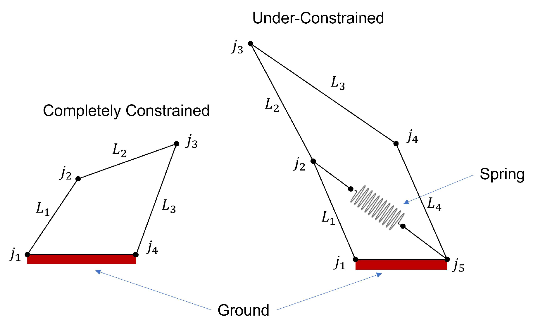
2.1. Completely Constrained Gripper Mechanism

Completely constrained finger mechanisms are devices with a DOF equivalent to their number of actuators, which allows the trajectory of the tip of the finger to follow a predefined path. Note that the number of DOF is computed using the Gruebler-Kutzbach [77] equation presented below:
M = 3 L 2 J
where M is the total DOF; L is the number of links, and J is the number of joints. Then, consider the completely constrained mechanism presented in Figure 3, with three links ( L i ) and four joints( j i ); applying Equation (1), the total number of DOF is one. Thus, this robot only needs one actuator to generate motion. This property permits the device to generate high output torque, allowing the gripper to hold heavy-weight objects [30,35]. Most of these devices use 1 DOF to control the motion of the gripper, which limits the complexity of the items that the gripper can handle [33]. To solve this issue, researchers have included more DOF in the grippers to enhance their ability to handle complex objects at the expense of their output torque [37]. Based on their design, completely constrained finger mechanisms have two classifications: compliant mechanisms and rigid links.

2.1.1. Compliant Mechanism

A compliant mechanism is a flexible mechanism that transmits force and motion through elastic deformations. Compliant mechanisms have a reduced number of moving parts which makes them light. Besides, friction impacts compliant mechanisms more than rigid links because they require fewer assembly parts. Moreover, the fewer assembly parts reduce undesirable nonlinear effects like backlash and noise on compliant mechanisms. Compliant mechanisms are usually of 3D printed materials, reducing their manufacturing cost. However, since the links are flexible, their considerably weaker than rigid links, reducing the output torque capabilities [78]. A usual design strategy for compliant mechanisms is topological optimization as proposed in [6] for a gripper of 3-flexible fingers. The principal purpose of the optimization was to facilitate the modeling of interactions between the gripper and the objects. Figure 4 presents the stages of optimization for the gripper design. The optimization model considers the loading pressure and traction frictions for this case to obtain the objective function. The obtained device uses pulleys and cables for actuation.
Another example of a compliant mechanism is used for each finger of a 3-finger flexible gripper in [1]. The finger mechanism performs linear motions as presented in Figure 5. The finger mechanism was fabricated with a thermoplastic elastomer (TPE) and was optimized for interactions with unpredictable environments and to handle delicate objects of different sizes. Additionally, the gripper mechanism has only one linear actuator to actuate the three fingers simultaneously, which generates the same displacement on each finger.
A similar design was proposed in [30], focusing on the optimal design of a 3D-printed constant force-compliant finger. This finger mechanism uses a force regulation strategy for high-speed handling of fragile objects. Details of the regulation strategy are presented in [31]. Figure 6 shows the gripper actuation system, including the jaw and the FRM. The gripper mechanism uses pneumatic actuation and has two complaint mechanisms acting as springs.
Other grippers integrate sensors in the design of the compliant gripper, as in [32]. This compliant gripper uses an integrated position and grasping/interaction force sensor for automated micro-assembly tasks. However, the integrated sensor limits the workspace to 2.2 mm with a grasping force of 16 mN. Although, this may not be an impending feature for the particular application of this gripper. Figure 7 presents the complaint mechanism with the integrated position and force sensors and a piezoresistive strain gauge for controlling the end-effector. This gripper mechanism also uses finite elements topological optimization. The author compared the results from the optimization with an experimental setup, validating the feasibility of this procedure.

2.1.2. Rigid Links

Opposite to compliant mechanisms, rigid links can generate a high output torque while maintaining their stiffness. However, this gripper mechanism requires force sensors to avoid damaging the handling objects. This architecture is presented in [39], which proposes a cable-driven adaptive multi-DOF finger with a mechanical sensor integrated to control the position and output torque. This finger mechanism is made of Acrylonitrile Butadiene Styrene (ABS) and can generate motions in a single plane. The design of this finger mechanism maximizes the output forces in a predefined path, obtaining a gripper mechanism that can hold objects of 55mm in diameter and 800 grams in weight. Figure 8 presents the kinematical diagram of the gripper mechanism for the design trajectory. Another rigid gripper example with similar capabilities is in [4]. This rigid gripper is a 4-finger hand gripper, each finger with three DOFs and actuated by cables. The hand gripper’s fingers have like dimensions and are composed of two phalanges. Other rigid grippers include variable friction surfaces which increase the manipulability dexterity of the gripper [40]. The texture of this gripper is a compound of Polylactic Acid (PLA) and TPU, and its friction changes by the actuation of two pulleys attached to DC motors as described by Figure 9.
One limitation of rigid links is the need for an accurate control strategy. This feature is complex to obtain because of the nature of the force sensor. Thus, some authors use a fuzzy logic controller to approximate the experimental results into an accurate control strategy [34]. Figure 10 presents the experimental setup used by the author to verify the behavior of this approach. Other rigid link designs use closed-loop links [79]. This finger gripper has two parallel grippers composed of symmetric parallelograms, as seen in Figure 11.
The advantage of this kinematical design is that the model is simpler to implement, ensuring that the tool reacts well relative to the gripping forces and the spring stiffness. Moreover, to increase the accuracy, some rigid links grippers use lead screws examples of this approach are in [33,35]. The former uses a gripper inspired by a chuck clamping device, as presented in Figure 12. This gripper has a closing motion mechanism that provides the position of objects. The latter uses a slider-crank-mechanism as shown in Figure 13. This rigid link mechanism can handle items up to 5kg or fragile objects like eggs. Both gripper mechanisms have the advantage of self-locking, which reduces energy consumption because the motors do not need to be active all the time. However, this type of gripper has a slow-motion issue because of its high mechanical advantage.
Other designs use electromagnets to actuate rigid links. For example, in [41] is proposed an electromagnet actuated gripper for the manipulation of fabrics. As presented in Figure 14, the gripper uses a slider-crank mechanism. More complex electromagnet-actuated grippers use multiobjective genetic algorithms for optimal design. An example is presented in [42] of this optimization strategy. For this purpose, the authors modeled the actuator as a stack consisting of individual actuator elements arranged in series and parallel arrays in four combinations. As a result of this optimization process, the gripper has increased accuracy compared with others grippers of the same type. However, using electromagnets demands a high energy input, making them unsuitable for autonomous applications.
The Salisbury hand [80] shown in Figure 15 was the first successful humanoid robot hand built as a sophisticated end-effector for grasping investigations. Each finger on this hand has three joints, allowing it to mimic the dexterous gripping of the human hand to some extent. Steel wires that pass through Teflon-coated flexible tubes activate the fingers. Each cable is tensioned by a DC brush-type motor that works through a gear reducer. The flexible conduit that allows wires to be routed around the wrist allows the actuator package to be mounted on the robot’s forearm.
The DHL Hand [81] is an open skeleton hand made of aluminum and steel that can manipulate a variety of objects with great dexterity and accuracy. Three separate joints in each finger are controlled by their own actuators. Brushless dc motors, tooth belts, harmonic drive gears, and bevel gears at the base joint are used in all actuation systems. As shown in Figure 16, the base joint is a differential bevel gear type, allowing for two independent motions. The two actuators can be used to their full capacity, allowing the joint to flex or extend as needed.
The Barrett hand [82] is a popular example of a hand used in industry and for grasping and manipulation research. Each Barrett Hand’s finger shown in Figure 17 is powered by a motor, and each motor controls two joint axes. Torque is applied to these joints via a Torque switch mechanism. When a fingertip makes contact with an object for the first time, it locks both joints, deactivates motor currents, and waits for further instructions from the microprocessors.

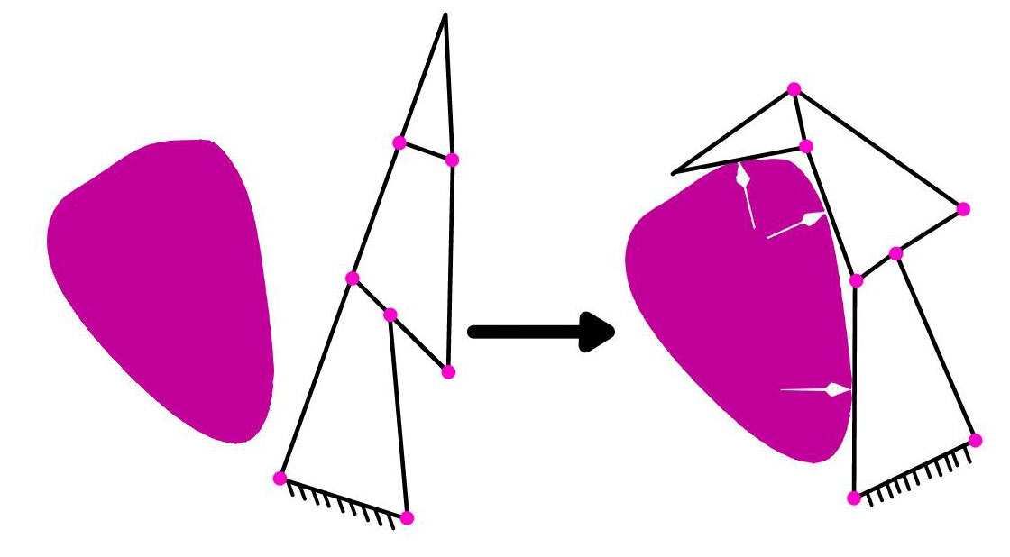
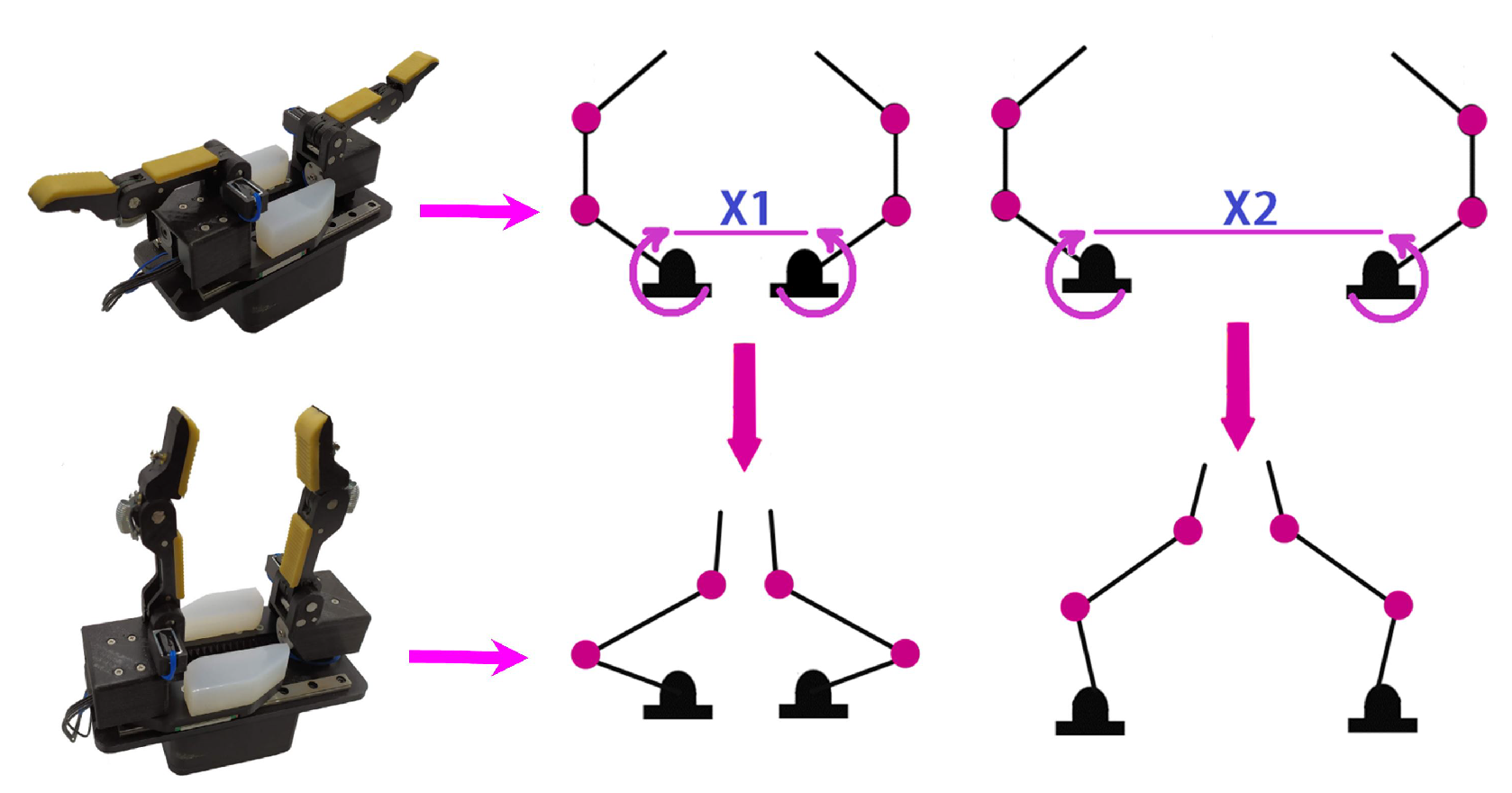
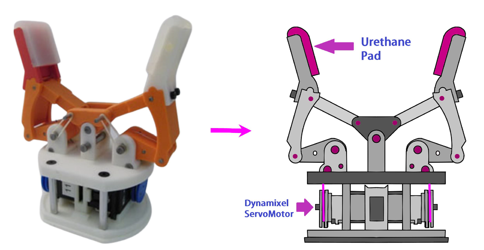
2.2. Underconstrained Mechanism

2.3. Compliant Mechanism

Underconstrained mechanisms allow a broader motion capability compared to completely constraints. The higher motion is due to the DOF, which is higher than the number of actuators, adding more flexibility to handle irregular shape objects. The extra DOF is usually passively actuated by springs for maintaining the structure, as presented in Figure 3, in which a 2-DOF under-constrained mechanism is presented. However, as is in the case of underconstrained compliant mechanisms, the shape of the gripper can include the effects of the spring without adding it. An example of this kind of mechanism is presented by the authors in [43], which developed a robotic gripper with compliant cell stacks for industrial part handling, shown in Figure 18.
Another example is presented in [44], who developed an underactuated robotic gripper of three fingers inspired by an origami twisted tower shown in Figure 19. Each of the fingers of the gripper uses cable-driven actuation controlled by a central servomotor. Although the gripper mechanisms can handle objects with complex shapes, their payload capacity is limited to 1.5 N at most. Other examples with the same issue include the works of the authors of [47], who developed a passive-compliant piezo actuated micro-gripper (Figure 20); and the designs in [45], which presents a 3D printed Gripper for Cloth Manipulation and position control (Figure 21). However, the latter implemented a variable friction finger surface, controlled by a small motor that pushes the high friction surface at the tip of the top finger, incrementing the payload capacity.
Another limitation of this type of gripper is the need for a force sensor capable of measuring the distribution of forces on a surface. To this end, the authors developed a gecko-inspired gripper that uses ABS polyimide or mylar polyester with a metalized surface for the sensors (Figure 22). The sensor is fabricated in situ with thin adhesive films on each finger and measures the change in capacitance when a region of adhesive makes contact with a surface. Another sensor is developed by the authors of [46] for a compliant adaptive gripper, which integrated an implicit force. The gripper can measure the output force by knowing the deformations on the gripper itself. To compute the deformation of the system, the authors used a general numerical network model (NTM). The NTM calculates the node coordinates of the mechanism using a hand-eye camera (Figure 23). Then, using the node information, the NTM computes the grasping force of the gripper. The proposed mechanism is the first fin-ray-based gripper that simultaneously achieves adaptive grasping and intrinsic force-sensing without any force sensor. A gripper with similar capabilities is presented in [48], who developed a novel compliant constant-force gripper based on buckled fixed-guided beams (Figure 24). The gripper has a passive type of compliant constant-force mechanism. The gripper can generate a constant-force output using a combination of positive and negative stiffness mechanisms. The negative stiffness mechanism is a bi-stable buckled fixed-guided beam.

2.4. Deformable Grippers

2.4.1. Single Mass Gripper

Single mass grippers handle items by deforming their shape. This kind of gripper does not have a straightforward relationship between the deformation and the actuator mechanism, as with completely-constrained or underconstrained grippers. Thus, single mass grippers deform until wrapping the desired object. This type of gripper uses pneumatic or cable-driven actuation, covering the broader scope of objects, independent of their shape. However, despite their abilities to manipulate objects, the use of pneumatic actuation limits the mobility of the gripper [8], which presents a prestressed soft gripper with three fingers for food handling. The actuator has 3D printed in two parts: a soft chamber with a rigid connector and a sealed cover. The soft chamber is prestressed by stretching and gluing a non-stretched cover (Figure 42). The gripper can realize a large contact area while grasping with a wide initial opening without deflating the soft actuators. The fingers/actuators are of Rubber-like material. The authors used an air compressor (JUN-AIR 3-4) and an electro-pneumatic regulator (SMC ITV2030) to pressurize the actuator. The soft actuator has a length of 87 mm and can pick up objects of 75.2 g with an accuracy of 80%. The author did a finite element simulation to obtain the optimal dimensions.
Other authors have similar issues [64], which presents a single mass soft robotic gripper embedded with Microneedles for handling delicate fabrics. The gripper material is of the elastomer kind. The gripper hooks the delicate fabrics using four microneedles. The actuator of the gripper is a vacuum pump that deforms the elastomer once it is in position for handling the fabrics (Figure 43). Although the author does not use any sensor for controlling the pressure, some solutions include embedding soft pressure sensors at the tip of the gripper. Besides its bulkiness, the vacuum pump requires more energy than a regular air compressor. Likewise, an origami-inspired gripper controlled by an SMA actuator is designed [11] for picking objects with variable shapes and sizes. The design of the gripper takes inspiration from a reconfigurable suction gripper (Figure 44). Constructed from rigid and soft components and driven by compact shape memory alloy actuators, the gripper can effectively self-fold into three shape modes. The main objective is to pick large and small, flat, narrow, cylindrical, triangular, and spherical objects ranging from 2 mm to 43 mm in diameter and less than 5.2 N of weight.
Other approaches use cable-driven actuation to reduce energy consumption and increase manipulability. However, controlling the gripper motion becomes an issue because of the complexity of the deformation model. The authors of [65] present an example of this kind of gripper. The authors developed a multi-legged gripper inspired by a gecko with a controllable adhesion parameter. The gripper can manipulate flat and curve objects by a self-adaptive dry adhesion system. The system consists of four symmetric adhesive units, each modulated by two adaptive-locking mechanisms for compression and rotation, respectively, and one peeling mechanism. The two adaptive-locking mechanisms can adapt to surfaces with height and curvature differences to ensure intimate contact with the objects (Figure 45). Moreover, the lock adaption configuration enables equal load sharing for a firm attachment. The peeling mechanism rapidly peels the adhesive surfaces from the substrate for easy detachment.
Another flat dry adhesive soft gripper was presented in [66], integrating a soft actuator, micro spine, and a bioinspired design based on a gecko’s toe and a cat’s foot. The soft gripper has an improved design that enhances the comprehensive grasping ability of the soft gripper on smooth or rough surfaces. The design emulates two phalanges, proximal and distal, using SMA coils (Figure 46). The SMA coils are on the backside of the base layer opposite an adhesive layer. A flexible sensor measures the force inside the finger between the two layers. The fingers have micro-needles for increased grasping ability. The viscoelastic mechanics model is used to formulate the preloading process of the adhesive relating the stress encountered by the adhesive with the contact area considered during the preloading process.

2.4.2. Single Mass Finger

Single mass fingers deform their shape to actuate each of their fingers. This gripper mechanism can hold objects of different forms because of the actuation of the fingers, having similar advantages and disadvantages to single mass grippers. Among the benefits, using multiple grippers facilitates controlling the gripper; an increase in the number of grippers allows a better distribution of the forces generated, relaxing the dependency on an accurate control strategy. However, for this kind of grippers, the issue of bulkiness is more notorious because the actuator requires to deform multiple fingers instead of only one structure. To present some examples, The soft robotic gripper shown in [7] uses a particle transmission and has three fingers. The fingers can grasp a wide range of objects such as a nipper plier, tape, haptic device, and an electric screwdriver. Moreover, the gripper has a vertical force gauge that measures a grasping force of around 20 N at the tip. The authors modeled the system using mass conservation and the principle of incompressible homogenous neo-Hookean materials [85]. Moreover, the authors used molded silicone rubber reinforced by double-stranded woven fiberglass thread and PLA to make the actuators (Figure 47). The proposed actuator design is a slightly modified model of the widely researched fiber-reinforced soft pneumatic actuator [86].
Moreover, a soft robotic gripper with an active palm and reconfigurable fingers is presented in [68] performing complex motions such as rolling a pen or pouring a glass of water. The gripper performs in multiple applications, such as robotic manipulation, medical applications, mobility, rehabilitation, or assistive robotics. The fingers of the gripper are of silicone elastomers EcoFlex. Stepper motors, micropumps, and solenoids control the position of the fingers (Figure 48). Each finger has three pneumatic chambers, which are independent, giving each finger a wide range of mobility. Optimization over a previous iteration is mentioned but not explained. However, the author performs a workspace analysis to determine the total active area. Additionally, the soft gripper shown in [67] is based on pre-charged pneumatic soft actuators. The gripper has a pre-charged pneumatic (PCP) with a silicone chamber with one air tube for pressurizing it (Figure 49). A check valve controls the pressure inside the silicone chamber. When the fingers are pressurized, their shape is corrected using tensile cables or tendons. The actuator body material is silicone rubber with an inextensible layer attached to the bottom of the actuator with a range of 150 mm and capable of holding soft objects like tomatoes or eggs.
Another gripper is in [69], including rigid and soft materials. The gripper has a pressuring single internal chamber that controls the position. The authors proposed this design to improve the fingertip force and actuation speed simultaneously, optimizing parameters like the degree of bending, the ratio of the rigid structure, the longitudinal strain by modifying the shape of the chamber, and the relation between soft and rigid materials in the same finger (Figure 50). Furthermore, two pneumatic pumps (DAO-370A) control the gripper, allowing a broad workspace suitable for teleoperation. The gripper can hold objects like a drill driver, a coffee cup, and a banana with a maximum allowable weight of 28.7 N. The design parameters were optimized by the finite elements method (FEM) and a simulation based on the hyperrealistic Mooney-Rivlin model.
Other designs include a pneumatically driven gripper with retractable, telescopic fingers as developed in [70] for Medical applications. The authors used two low-pressure mini-air pumps to actuate this silicone rubber gripper. Additionally, the authors implemented an optical motion capture system composed of eight cameras to track the angular displacement of the gripper (Figure 51). The gripper has retroreflective markers at the top surface of the actuator to increase the accuracy of the measure. The range of motion of the soft actuator is 0 to 105 degrees. The gripper can hold objects like a medium mustard bottle, a water bottle, an egg, and a drill driver whit a grasp up to 14.53 N. A Finite Element Analysis (FEA) model of the soft actuator deformation was developed to understand the structure’s inflation behavior.
Similarly, the pneumatic two-finger soft robotic gripper shown in [71] can handle objects with enveloping and pinching grasping modes (Figure 52). This gripper consists of chambers and channels in a series arrangement. Moreover, the gripper includes a main body with a bottom both an inextensible elastomer. It combines two dual-module pneumatic actuators with a variable chamber height. The gripper has a workspace with a Bending angle of up to 250 degrees but a low payload of up to 4 N. A digital force gauge inside the finger measures the force at different chamber points. The pinching grasping mode was mainly analyzed by FE analysis and experiments.
Other approaches use a soft robotic gripper with Gecko-inspired adhesive as proposed in [72], which can handle rocky or dirty surfaces where adhesion is limited. Gecko-inspired grippers use a combination of fluidic elastomer actuators as an actuation mechanism that goes through a circular cross-section (Figure 53). Gecko elastomer actuators provide improved control authority for manipulation tasks. The ability to achieve higher ultimate grip strengths on many objects allows manipulation of heavier objects and higher accelerations of objects during motion. This property is significant for pick and place operations, where speed is critical. The gecko elastomer actuator maintains a low energy input and a fast actuation since the actuators are optimized for these properties while using adhesion-enhanced friction for higher strength grips.
Lastly, an underwater gripper studying the deformation characteristics of water hydraulic flexible actuators is shown in [73]. The gripper has three fingers. Each of the fingers has an inner skeleton made of 3J1, 3J21, TC4, and Carbon fiber with a wall thickness of 1 mm and 30 mm for the first knuckle and 80 mm for the second knuckle. A nonlinear equation expresses the workspace. According to the equation, when the inlet pressure is 0 or 10 MPa, the minimum and maximum deformation of the flexible actuator are 0 mm and 0.20213 mm, respectively. The authors investigated using simulations the effects of different inlet pressure, knuckle length, wall thickness, and material of the inner skeleton and external surface on the deformation characteristics of the flexible actuator. Figure 54 shows the theoretical deflection of the internal bar of the gripper and its repercussion on the external coating. According to the authors, the wall thickness and the length between the knuckles significantly affect the gripper deformation.

2.4.3. Materials of the Deformable Grippers

Most single-mass grippers and single-mass fingers are of silicone or rubber-like materials. Rubber-like materials have elasticity, and structural compliance, which increases the safety and adaptability of the device when interacting with delicate or fragile objects [70]. However, rubber-like materials come with disadvantages; the fabrication of soft grippers often requires an iterated casting process, which is usually complex and time-consuming. Furthermore, the air bubbles within the material often result in significant individual differences, which limits the robot’s repeatability [8]. An example of rubber-like material is the commercial ECOFLEX silicone 00-30, which is easy and fast to actuate thanks to its flexibility [87]. Moreover, ECOFLEX silicone 00-30 has a high-power-to-weight ratio, which allows it to have large deformations with a small input [88]. However, the analysis and design of this rubber-like material are complex due to its highly nonlinear response. Thus, when analytical solutions are required, researchers use models similar to the neo-Hookean, which are limited in representing the material behavior at large stretches [88]. Thus, an option is using finite element (FE) analysis, especially when considering the response of silicone rubber actuators [86,87,89,90,91].
Other rubber-like materials include the Object Full cure 930 TangoPlus, which can be 3D printed. Although this material has a higher resistance than the ECOFLEX silicone 00-30, it has the limitation of less elongation break and more cost [88]. Another example of 3D printed rubber-like material is found in [92], NinjaFlex. Although this material has a high resistance, it has a high hardness, which is unsuitable for applications requiring low pressure or force.
Some rubber-like materials can be prepared with a wide range of cured stiffnesses; such materials include the Dragonskin 20, and VTV800 [93]. However, these materials may need an external force or vibrators to recover their initial shape [7].
Other materials include the Dielectric Elastomer Actuators (DEA) or smart material. This material can be used as an actuator for the gripper. Moreover, grippers with this material have reported good performance while grasping various objects [94]. Additionally, soft grippers with this technology report fast response while consuming very-low energy [95]. However, most DEA grippers require a rigid frame to pre-stretch the high elastomer, which is a complex process. Another issue is the reliability of the flexible electrode, which deteriorates with time. Lastly, DEA grippers are limited to low-weight objects because of limitations in the voltage [73].

3. Principal Findings

Table 2 summarizes our findings of the robotic arm grippers handling different sizes, shapes, and materials of objects. In the size category, this table groups the gripper by small, medium, and large size of the handling object. Additionally, this table considers the most common shapes to classify the handling objects, i.e., circular, square, and irregular. The last criteria of comparison consider the types of objects handled by the grippers as delicate, fabric, electronics, rocks and soils, and food. According to the findings presented in the table, the best grippers to handle irregular objects are deformable single-mass grippers; this is because of the adapting capabilities of those grippers. However, the most widely used gripper for daily objects is the underconstrained-rigid links; this is due to this type of gripper is easier to build, requiring a more available actuation system as is linear or rotary actuators. Finally, Table 3 presents the principal findings of each main design category of grippers. This table presents the principal qualities of each gripper type, the load capacity, the range capacity, and the type of objects that each category can hold.

4. Conclusions

The main contribution of this paper is the review of the majority of robotic grippers from the last four years. We classified the gripper according to the number of DOF, the actuation system, the design approach, and the shape of the grasping objects. For each classification criterion, a comparison of the advantages and disadvantages is presented, obtaining insights into which is the gripper design with the broader capabilities. Thus, the principal conclusions of our study are as follows:
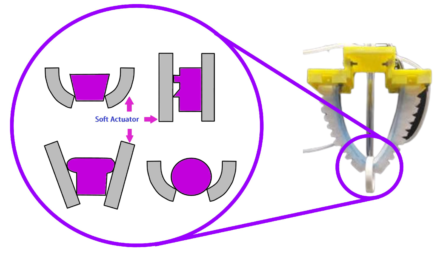
  • The sensing of the forces generated by the grasping is not accurate. Thus, to avoid breaking fragile objects, engineers use deformable grippers.
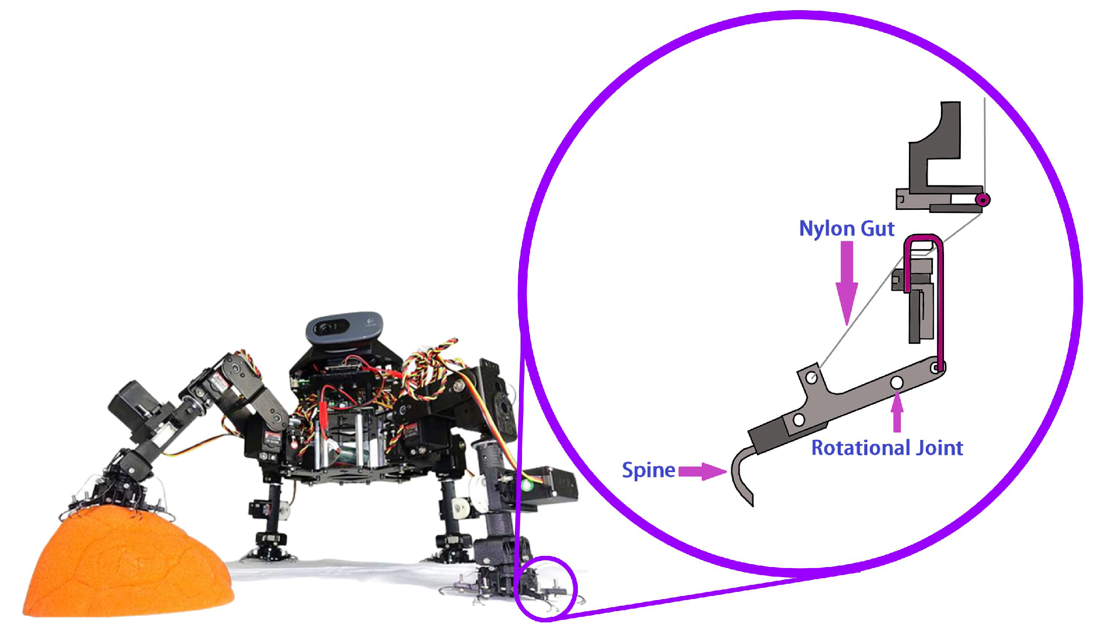
  • Another issue is the glide of objects, which creates issues in the control strategy. Thus, a solution for this subject is variable friction in the gripper found in gecko-inspired grippers.
  • The issue of the sensing forces is handled by completely constrained grippers which can exert greater forces with precision, especially in applications where heavy objects must be moved. However, it cannot be attached to different shapes with ease.
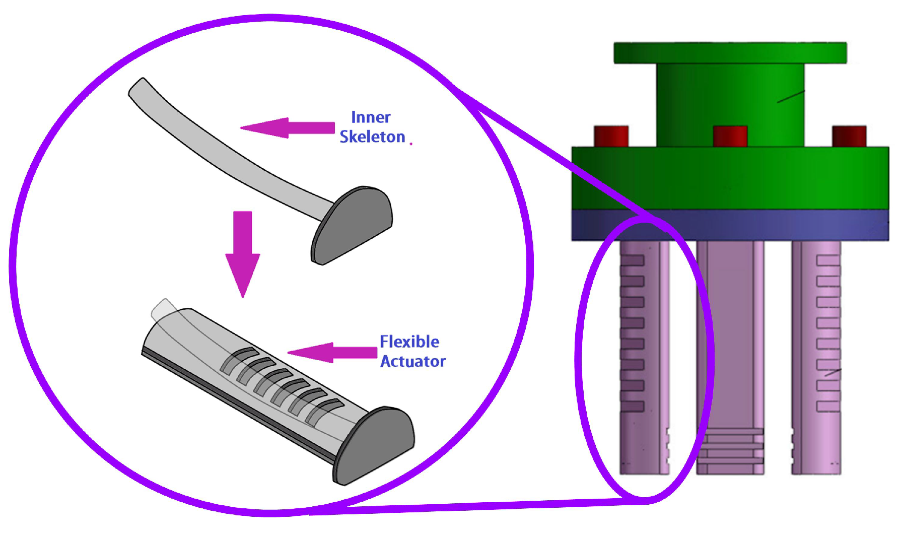
  • Another option for deformable grippers is passive-compliant mechanisms that add an extra DOF to increase the manipulability. Passive-compliant mechanisms have the advantage of exerting a moderate amount of output force, adequate for handling objects with a moderate weight, especially if they are built using rigid links.
  • Passive compliant mechanisms offers a balance between flexibility and strength. Possessing rigid joints, it can support heavy weights while adapting to most objects’ shapes. As a result, it is ideal for applications where the environment is uncontrolled or unpredictable
Thus, based on our analysis, we conclude that the gripper design with the best capabilities for handling objects of different weights and shapes is a passive-compliant mechanism with rigid links and a gecko-inspired surface. The only disadvantage of this application depends on the exposure to environmental contaminants that may deteriorate the capabilities of the gecko-inspired surface to graduate friction.

Author Contributions

Conceptualization, J.H., M.S.H.S. and J.S.; methodology, J.H. and M.S.H.S.; formal analysis, J.H., M.S.H.S. and J.S.; investigation, J.H., M.S.H.S., I.R., M.I.I.Z. and J.S.; resources, M.H.R.; writing—original draft preparation, J.H., M.S.H.S., I.R., M.I.I.Z. and J.S.; writing—review and editing, J.H., M.S.H.S., H.U.A., J.S. and M.H.R.; visualization, J.H. and M.S.H.S.; supervision, M.H.R.; project administration, M.H.R.; funding acquisition, M.H.R. and S.I.A. All authors have read and agreed to the published version of the manuscript.

Funding

The contents of this research were supported by a grant from the National Institute on Disability, Independent Living, and Rehabilitation Research (NIDILRR grant number 90DPGE0018-01-00). NIDILRR is a Center within the Administration for Community Living (ACL), Department of Health and Human Services (HHS). The contents of this research do not necessarily represent the policy of NIDILRR, ACL, or HHS, and you should not assume endorsement by the Federal Government.

Institutional Review Board Statement

Not applicable.

Informed Consent Statement

Not applicable.

Data Availability Statement

Not applicable.

Conflicts of Interest

The authors declare no conflict of interest.

Abbreviations

The following abbreviations are used in this manuscript:
DOFDegree of Freedom
TPEThermoplastic Elastomer
FRMFlexible Redundant Robot Manipulators
ABSAcrylonitrile Butadiene Styrene
PLAPolylactic Acid
TPUThermoplastic polyurethane
BLDCBrushless DC Motor
PIDProportional-Integral-Derivative feedback control
NTMNumerical Network Model
RTVsoft, adherent, clear silicone elastomer gel
3J1Nickel-based high elastic alloy
3J21Cobalt based high elastic alloy
TC4Titanium Alloy

Appendix A. Journal Selection

Studies focused on current design and control approaches for the robotic arm gripper were chosen by performing a systematic electronic search in a handful of databases in January 2022. The timeline of the studies was limited to the last five years to focus on the recent advancement in this field to focus on the recent advances in this field, the study was restricted to the last five years. Keywords used to search include “robotic gripper”, “robotic hand”, “gripper design”, “robotic manipulation”, and “robotic grasping”. Several databases were searched for this research: Google Scholar, IEEE Xplore, ScienceDirect, Engineering Village, Microsoft academic search, Google Patent Search, Scopus, Springer, PubMed, MDPI, IOS Press, Hindawi, SAGE, PLOS, Frontiers in Robotics and AI, etc. Around 235 publications are identified for consideration in this search. However, after some initial screening, 190 studies were shortlisted for review. A few publications were excluded based on eligibility criteria (specific goals, duplication, review, etc.), which resulted in 64 studies being selected for an in-depth review. All the selected papers (n = 64) were reviewed, including abstracts, introductions, design approach, experiments, conclusions, and future work sections to identify any other noteworthy information, such as the addressed problem, contribution, control theory, applications, experiments, used material, and sensors. Figure A1 shows the systematic approach with inclusion and exclusion criteria for the selected studies.
Figure A1. Inclusion and exclusion criteria of the selected studies.
Robotics 12 00005 g0a1

References

  1. Liu, C.H.; Chung, F.M.; Chen, Y.; Chiu, C.H.; Chen, T.L. Optimal Design of a Motor-Driven Three-Finger Soft Robotic Gripper. IEEE/ASME Trans. Mechatron. 2020, 25, 1830–1840. [Google Scholar] [CrossRef]
  2. Birglen, L.; Schlicht, T. A statistical review of industrial robotic grippers. Robot. Comput.-Integr. Manuf. 2018, 49, 88–97. [Google Scholar] [CrossRef]
  3. Choi, B.; Choi, H.R.; Kang, S. Development of tactile sensor for detecting contact force and slip. In Proceedings of the 2005 IEEE/RSJ International Conference on Intelligent Robots and Systems, Edmonton, AB, Canada, 2–6 August 2005; pp. 2638–2643. [Google Scholar] [CrossRef]
  4. Cannata, G.; Maggiali, M. An embedded tactile and force sensor for robotic manipulation and grasping. In Proceedings of the 5th IEEE-RAS International Conference on Humanoid Robots, Tsukuba, Japan, 5–7 December 2005; pp. 80–85. [Google Scholar] [CrossRef]
  5. Nagaoka, K.; Minote, H.; Maruya, K.; Shirai, Y.; Yoshida, K.; Hakamada, T.; Sawada, H.; Kubota, T. Passive Spine Gripper for Free-Climbing Robot in Extreme Terrain. IEEE Robot. Autom. Lett. 2018, 3, 1765–1770. [Google Scholar] [CrossRef]
  6. Chen, F.; Xu, W.; Zhang, H.; Wang, Y.; Cao, J.; Wang, M.Y.; Ren, H.; Zhu, J.; Zhang, Y.F. Topology Optimized Design, Fabrication, and Characterization of a Soft Cable-Driven Gripper. IEEE Robot. Autom. Lett. 2018, 3, 2463–2470. [Google Scholar] [CrossRef]
  7. Li, Y.; Chen, Y.; Yang, Y.; Li, Y. Soft Robotic Grippers Based on Particle Transmission. IEEE/ASME Trans. Mechatron. 2019, 24, 969–978. [Google Scholar] [CrossRef]
  8. Wang, Z.; Torigoe, Y.; Hirai, S. A Prestressed Soft Gripper: Design, Modeling, Fabrication, and Tests for Food Handling. IEEE Robot. Autom. Lett. 2017, 2, 1909–1916. [Google Scholar] [CrossRef]
  9. Backus, S.B.; Dollar, A.M. An Adaptive Three-Fingered Prismatic Gripper With Passive Rotational Joints. IEEE Robot. Autom. Lett. 2016, 1, 668–675. [Google Scholar] [CrossRef]
  10. Yoon, D.; Choi, Y. Analysis of Fingertip Force Vector for Pinch-Lifting Gripper With Robust Adaptation to Environments. IEEE Trans. Robot. 2021, 37, 1127–1143. [Google Scholar] [CrossRef]
  11. Zhakypov, Z.; Heremans, F.; Billard, A.; Paik, J. An Origami-Inspired Reconfigurable Suction Gripper for Picking Objects With Variable Shape and Size. IEEE Robot. Autom. Lett. 2018, 3, 2894–2901. [Google Scholar] [CrossRef] [Green Version]
  12. Rojas, N.; Ma, R.R.; Dollar, A.M. The GR2 Gripper: An Underactuated Hand for Open-Loop In-Hand Planar Manipulation. IEEE Trans. Robot. 2016, 32, 763–770. [Google Scholar] [CrossRef]
  13. Ward-Cherrier, B.; Rojas, N.; Lepora, N.F. Model-Free Precise in-Hand Manipulation with a 3D-Printed Tactile Gripper. IEEE Robot. Autom. Lett. 2017, 2, 2056–2063. [Google Scholar] [CrossRef] [Green Version]
  14. Hashizume, J.; Huh, T.M.; Suresh, S.A.; Cutkosky, M.R. Capacitive Sensing for a Gripper With Gecko-Inspired Adhesive Film. IEEE Robot. Autom. Lett. 2019, 4, 677–683. [Google Scholar] [CrossRef]
  15. Elangovan, N.; Gerez, L.; Gao, G.; Liarokapis, M. Improving Robotic Manipulation Without Sacrificing Grasping Efficiency: A Multi-Modal, Adaptive Gripper With Reconfigurable Finger Bases. IEEE Access 2021, 9, 83298–83308. [Google Scholar] [CrossRef]
  16. Brown, E.; Rodenberg, N.; Amend, J.; Mozeika, A.; Steltz, E.; Zakin, M.R.; Lipson, H.; Jaeger, H.M. Universal robotic gripper based on the jamming of granular material. Proc. Natl. Acad. Sci. USA 2010, 107, 18809–18814. [Google Scholar] [CrossRef] [Green Version]
  17. Makiyama, Y.; Wang, Z.; Hirai, S. A Pneumatic Needle Gripper for Handling Shredded Food Products. In Proceedings of the 2020 IEEE International Conference on Real-Time Computing and Robotics (RCAR), Hokkaido, Japan, 28–29 September 2020; IEEE: Piscataway, NJ, USA, 2020; pp. 183–187. [Google Scholar]
  18. Zhang, B.; Xie, Y.; Zhou, J.; Wang, K.; Zhang, Z. State-of-the-art robotic grippers, grasping and control strategies, as well as their applications in agricultural robots: A review. Comput. Electron. Agric. 2020, 177, 105694. [Google Scholar] [CrossRef]
  19. Hughes, J.; Culha, U.; Giardina, F.; Guenther, F.; Rosendo, A.; Iida, F. Soft manipulators and grippers: A review. Front. Robot. AI 2016, 3, 69. [Google Scholar] [CrossRef] [Green Version]
  20. Wang, J.; Gao, D.; Lee, P.S. Recent Progress in Artificial Muscles for Interactive Soft Robotics. Adv. Mater. 2021, 33, 2003088. [Google Scholar] [CrossRef]
  21. Laschi, C.; Mazzolai, B.; Cianchetti, M. Soft robotics: Technologies and systems pushing the boundaries of robot abilities. Sci. Robot. 2016, 1, eaah3690. [Google Scholar] [CrossRef]
  22. Bicchi, A.; Kumar, V. Robotic grasping and contact: A review. In Proceedings of the 2000 ICRA. Millennium Conference. IEEE International Conference on Robotics and Automation. Symposia Proceedings (Cat. No. 00CH37065), San Francisco, CA, USA, 24–28 April 2000; IEEE: Piscataway, NJ, USA, 2000; Volume 1, pp. 348–353. [Google Scholar]
  23. Samadikhoshkho, Z.; Zareinia, K.; Janabi-Sharifi, F. A brief review on robotic grippers classifications. In Proceedings of the 2019 IEEE Canadian Conference of Electrical and Computer Engineering (CCECE), Edmonton, AB, Canada, 5–8 May 2019; IEEE: Piscataway, NJ, USA, 2019; pp. 1–4. [Google Scholar]
  24. Mukhtar, M. Design, Modelling, and Control of an Ambidextrous Robot Arm. Ph.D. Thesis, Brunel University London, London, UK, 2020. [Google Scholar]
  25. Taheri, O.; Ghorbani, N.; Black, M.J.; Tzionas, D. GRAB: A dataset of whole-body human grasping of objects. In Proceedings of the European Conference on Computer Vision, Glasgow, UK, 23–28 August 2020; Springer: Cham, Switzerland, 2020; pp. 581–600. [Google Scholar]
  26. Cini, F.; Ortenzi, V.; Corke, P.; Controzzi, M. On the choice of grasp type and location when handing over an object. Sci. Robot. 2019, 4, eaau9757. [Google Scholar] [CrossRef]
  27. Feix, T.; Bullock, I.M.; Dollar, A.M. Analysis of human grasping behavior: Object characteristics and grasp type. IEEE Trans. Haptics 2014, 7, 311–323. [Google Scholar] [CrossRef]
  28. Prakash, B.; Veeregowda, B.; Krishnappa, G. Biofilms: A survival strategy of bacteria. Curr. Sci. 2003, 85, 1299–1307. [Google Scholar]
  29. Song, E.J.; Lee, J.S.; Moon, H.; Choi, H.R.; Koo, J.C. A Multi-Curvature, Variable Stiffness Soft Gripper for Enhanced Grasping Operations. Actuators 2021, 10, 316. [Google Scholar] [CrossRef]
  30. Liu, C.H.; Chung, F.M.; Ho, Y.P. Topology Optimization for Design of a 3D-Printed Constant-Force Compliant Finger. IEEE/ASME Trans. Mechatron. 2021, 26, 1828–1836. [Google Scholar] [CrossRef]
  31. Chen, C.C.; Lan, C.C. An Accurate Force Regulation Mechanism for High-Speed Handling of Fragile Objects Using Pneumatic Grippers. IEEE Trans. Autom. Sci. Eng. 2018, 15, 1600–1608. [Google Scholar] [CrossRef]
  32. Xu, Q. Design and Development of a Novel Compliant Gripper With Integrated Position and Grasping/Interaction Force Sensing. IEEE Trans. Autom. Sci. Eng. 2017, 14, 1415–1428. [Google Scholar] [CrossRef]
  33. Suebsomran, A. Development of Robot Gripper and Force Control. In Proceedings of the 2018 13th World Congress on Intelligent Control and Automation (WCICA), Changsha, China, 4–8 July 2018; pp. 433–437. [Google Scholar] [CrossRef]
  34. Zaki, A.M.; Soliman, A.M.; Mahgoub, O.A.; El-Shafei, A. Design and implementation of efficient intelligent robotic gripper. In Proceedings of the 2010 International Conference on Modelling, Identification and Control, Okayama City, Japan, 17–19 July 2010; pp. 710–716. [Google Scholar]
  35. Nishimura, T.; Tennomi, M.; Suzuki, Y.; Tsuji, T.; Watanabe, T. Lightweight, High-Force Gripper Inspired by Chuck Clamping Devices. IEEE Robot. Autom. Lett. 2018, 3, 1354–1361. [Google Scholar] [CrossRef]
  36. Nie, K.; Wan, W.; Harada, K. A Hand Combining Two Simple Grippers to Pick Up and Arrange Objects for Assembly. IEEE Robot. Autom. Lett. 2019, 4, 958–965. [Google Scholar] [CrossRef] [Green Version]
  37. Mahmoud, R.; Ueno, A.; Tatsumi, S. Dexterous mechanism design for an anthropomorphic artificial hand: Osaka City University Hand I. In Proceedings of the 2010 10th IEEE-RAS International Conference on Humanoid Robots, Nashville, TN, USA, 6–8 December 2010; pp. 180–185. [Google Scholar] [CrossRef]
  38. Wattanasiri, P.; Tangpornprasert, P.; Virulsri, C. Design of Multi-Grip Patterns Prosthetic Hand With Single Actuator. IEEE Trans. Neural Syst. Rehabil. Eng. 2018, 26, 1188–1198. [Google Scholar] [CrossRef]
  39. Wu, C.; Song, T.; Wu, Z.; Cao, Q.; Fei, F.; Yang, D.; Xu, B.; Song, A. Development and Evaluation of an Adaptive Multi-DOF Finger with Mechanical-Sensor Integrated for Prosthetic Hand. Micromachines 2021, 12, 33. [Google Scholar] [CrossRef]
  40. Lu, Q.; Clark, A.B.; Shen, M.; Rojas, N. An Origami-Inspired Variable Friction Surface for Increasing the Dexterity of Robotic Grippers. IEEE Robot. Autom. Lett. 2020, 5, 2538–2545. [Google Scholar] [CrossRef]
  41. Marullo, S.; Bartoccini, S.; Salvietti, G.; Iqbal, M.Z.; Prattichizzo, D. The Mag-Gripper: A Soft-Rigid Gripper Augmented With an Electromagnet to Precisely Handle Clothes. IEEE Robot. Autom. Lett. 2020, 5, 6591–6598. [Google Scholar] [CrossRef]
  42. Datta, R.; Pradhan, S.; Bhattacharya, B. Analysis and Design Optimization of a Robotic Gripper Using Multiobjective Genetic Algorithm. IEEE Trans. Syst. Man Cybern. Syst. 2016, 46, 16–26. [Google Scholar] [CrossRef]
  43. Netzev, M.; Angleraud, A.; Pieters, R. Soft Robotic Gripper With Compliant Cell Stacks for Industrial Part Handling. IEEE Robot. Autom. Lett. 2020, 5, 6821–6828. [Google Scholar] [CrossRef]
  44. Lee, K.; Wang, Y.; Zheng, C. TWISTER Hand: Underactuated Robotic Gripper Inspired by Origami Twisted Tower. IEEE Trans. Robot. 2020, 36, 488–500. [Google Scholar] [CrossRef]
  45. Donaire, S.; Borràs, J.; Alenyà, G.; Torras, C. A Versatile Gripper for Cloth Manipulation. IEEE Robot. Autom. Lett. 2020, 5, 6520–6527. [Google Scholar] [CrossRef]
  46. Xu, W.; Zhang, H.; Yuan, H.; Liang, B. A Compliant Adaptive Gripper and Its Intrinsic Force Sensing Method. IEEE Trans. Robot. 2021, 37, 1584–1603. [Google Scholar] [CrossRef]
  47. Chen, F.; Gao, Y.; Dong, W.; Du, Z. Design and Control of a Passive Compliant Piezo-Actuated Micro-Gripper With Hybrid Flexure Hinges. IEEE Trans. Ind. Electron. 2021, 68, 11168–11177. [Google Scholar] [CrossRef]
  48. Liu, Y.; Zhang, Y.; Xu, Q. Design and Control of a Novel Compliant Constant-Force Gripper Based on Buckled Fixed-Guided Beams. IEEE/ASME Trans. Mechatron. 2017, 22, 476–486. [Google Scholar] [CrossRef]
  49. Birglen, L.; Gosselin, C. On the force capability of underactuated fingers. In Proceedings of the 2003 IEEE International Conference on Robotics and Automation (Cat. No.03CH37422), Taipei, Taiwan, 4–19 September 2003; Volume 1, pp. 1139–1145. [Google Scholar] [CrossRef]
  50. Fontanelli, G.A.; Paduano, G.; Caccavale, R.; Arpenti, P.; Lippiello, V.; Villani, L.; Siciliano, B. A Reconfigurable Gripper for Robotic Autonomous Depalletizing in Supermarket Logistics. IEEE Robot. Autom. Lett. 2020, 5, 4612–4617. [Google Scholar] [CrossRef]
  51. Telegenov, K.; Tlegenov, Y.; Shintemirov, A. An underactuated adaptive 3D printed robotic gripper. In Proceedings of the 2014 10th France-Japan/8th Europe-Asia Congress on Mecatronics (MECATRONICS2014-Tokyo), Tokyo, Japan, 27–29 November 2014; pp. 110–115. [Google Scholar] [CrossRef]
  52. Li, X.L.; Wu, L.C.; Lan, T.Y. A 3D-Printed Robot Hand with Three Linkage-Driven Underactuated Fingers. Int. J. Autom. Comput. 2018, 15, 593–602. [Google Scholar] [CrossRef]
  53. Tlegenov, Y.; Telegenov, K.; Shintemirov, A. An open-source 3D printed underactuated robotic gripper. In Proceedings of the 2014 IEEE/ASME 10th International Conference on Mechatronic and Embedded Systems and Applications (MESA), Senigallia, Italy, 10–12 September 2014; pp. 1–6. [Google Scholar] [CrossRef] [Green Version]
  54. Telegenov, K.; Tlegenov, Y.; Shintemirov, A. A Low-Cost Open-Source 3-D-Printed Three-Finger Gripper Platform for Research and Educational Purposes. IEEE Access 2015, 3, 638–647. [Google Scholar] [CrossRef]
  55. Birglen, L.; Gosselin, C.M. Geometric Design of Three-Phalanx Underactuated Fingers. J. Mech. Des. 2005, 128, 356–364. Available online: http://xxx.lanl.gov/abs/https://asmedigitalcollection.asme.org/mechanicaldesign/article-pdf/128/2/356/5688285/356_1.pdf (accessed on 31 December 2022). [CrossRef]
  56. Birglen, L.; Gosselin, C. Kinetostatic analysis of underactuated fingers. IEEE Trans. Robot. Autom. 2004, 20, 211–221. [Google Scholar] [CrossRef]
  57. Melchiorri, C.; Vassura, G. Design of a Three-Finger Gripper for Intra-Vehicular Robotic Manipulation. In Proceedings of the IFAC Workshop on Space Robotics (SPRO’98), St-Hubert, QC, Canada, 19–22 October 1998; IFAC Proceedings Volumes. Volume 31, pp. 7–12. [Google Scholar] [CrossRef]
  58. Kim, Y.J.; Song, H.; Maeng, C.Y. BLT Gripper: An Adaptive Gripper With Active Transition Capability Between Precise Pinch and Compliant Grasp. IEEE Robot. Autom. Lett. 2020, 5, 5518–5525. [Google Scholar] [CrossRef]
  59. Firouzeh, A.; Paik, J. Grasp Mode and Compliance Control of an Underactuated Origami Gripper Using Adjustable Stiffness Joints. IEEE/ASME Trans. Mechatron. 2017, 22, 2165–2173. [Google Scholar] [CrossRef]
  60. Ko, T. A Tendon-Driven Robot Gripper With Passively Switchable Underactuated Surface and its Physics Simulation Based Parameter Optimization. IEEE Robot. Autom. Lett. 2020, 5, 5002–5009. [Google Scholar] [CrossRef]
  61. Hussain, I.; Renda, F.; Iqbal, Z.; Malvezzi, M.; Salvietti, G.; Seneviratne, L.; Gan, D.; Prattichizzo, D. Modeling and Prototyping of an Underactuated Gripper Exploiting Joint Compliance and Modularity. IEEE Robot. Autom. Lett. 2018, 3, 2854–2861. [Google Scholar] [CrossRef]
  62. Lee, W.C.; Wu, C.W. Design and analysis of a novel robotic gripper integrated with a three-phalanx finger. Proc. Inst. Mech. Eng. Part J. Mech. Eng. Sci. 2014, 228, 1786–1796. [Google Scholar] [CrossRef]
  63. Su, Y.; Fang, Z.; Zhu, W.; Sun, X.; Zhu, Y.; Wang, H.; Tang, K.; Huang, H.; Liu, S.; Wang, Z. A High-Payload Proprioceptive Hybrid Robotic Gripper With Soft Origamic Actuators. IEEE Robot. Autom. Lett. 2020, 5, 3003–3010. [Google Scholar] [CrossRef]
  64. Ku, S.; Myeong, J.; Kim, H.Y.; Park, Y.L. Delicate Fabric Handling Using a Soft Robotic Gripper With Embedded Microneedles. IEEE Robot. Autom. Lett. 2020, 5, 4852–4858. [Google Scholar] [CrossRef]
  65. Li, X.; Li, X.; Li, L.; Meng, Y.; Tian, Y. Load Sharing Design of a Multi-legged Adaptable Gripper With Gecko-Inspired Controllable Adhesion. IEEE Robot. Autom. Lett. 2021, 6, 8482–8489. [Google Scholar] [CrossRef]
  66. Hu, Q.; Dong, E.; Sun, D. Soft Gripper Design Based on the Integration of Flat Dry Adhesive, Soft Actuator, and Microspine. IEEE Trans. Robot. 2021, 37, 1065–1080. [Google Scholar] [CrossRef]
  67. Li, Y.; Chen, Y.; Li, Y. Pre-Charged Pneumatic Soft Gripper With Closed-Loop Control. IEEE Robot. Autom. Lett. 2019, 4, 1402–1408. [Google Scholar] [CrossRef]
  68. Pagoli, A.; Chapelle, F.; Corrales, J.A.; Mezouar, Y.; Lapusta, Y. A Soft Robotic Gripper With an Active Palm and Reconfigurable Fingers for Fully Dexterous In-Hand Manipulation. IEEE Robot. Autom. Lett. 2021, 6, 7706–7713. [Google Scholar] [CrossRef]
  69. Park, W.; Seo, S.; Bae, J. A Hybrid Gripper With Soft Material and Rigid Structures. IEEE Robot. Autom. Lett. 2019, 4, 65–72. [Google Scholar] [CrossRef]
  70. Gao, G.; Chang, C.M.; Gerez, L.; Liarokapis, M. A Pneumatically Driven, Disposable, Soft Robotic Gripper Equipped With Multi-Stage, Retractable, Telescopic Fingers. IEEE Trans. Med. Robot. Bionics 2021, 3, 573–582. [Google Scholar] [CrossRef]
  71. Liu, S.; Wang, F.; Liu, Z.; Zhang, W.; Tian, Y.; Zhang, D. A Two-Finger Soft-Robotic Gripper With Enveloping and Pinching Grasping Modes. IEEE/ASME Trans. Mechatron. 2021, 26, 146–155. [Google Scholar] [CrossRef]
  72. Glick, P.; Suresh, S.A.; Ruffatto, D.; Cutkosky, M.; Tolley, M.T.; Parness, A. A Soft Robotic Gripper With Gecko-Inspired Adhesive. IEEE Robot. Autom. Lett. 2018, 3, 903–910. [Google Scholar] [CrossRef]
  73. Nie, S.; Liu, X.; Ji, H.; Ma, Z.; Yin, F. Simulation and Experiment Study on Deformation Characteristics of the Water Hydraulic Flexible Actuator Used for the Underwater Gripper. IEEE Access 2020, 8, 191447–191459. [Google Scholar] [CrossRef]
  74. Hwang, G.; Park, J.; Cortes, D.S.D.; Hyeon, K.; Kyung, K.U. Electroadhesion-Based High-Payload Soft Gripper With Mechanically Strengthened Structure. IEEE Trans. Ind. Electron. 2022, 69, 642–651. [Google Scholar] [CrossRef]
  75. Krahn, J.M.; Fabbro, F.; Menon, C. A Soft-Touch Gripper for Grasping Delicate Objects. IEEE/ASME Trans. Mechatron. 2017, 22, 1276–1286. [Google Scholar] [CrossRef]
  76. Li, L.; Jin, T.; Tian, Y.; Yang, F.; Xi, F. Design and Analysis of a Square-Shaped Continuum Robot With Better Grasping Ability. IEEE Access 2019, 7, 57151–57162. [Google Scholar] [CrossRef]
  77. Sanjuan, J.; Serje, D.; Pacheco, J. Closed form solution for direct and inverse kinematics of a US-RS-RPS 2-DOF parallel robot. Sci. Iran. 2018, 25, 2144–2154. [Google Scholar] [CrossRef]
  78. Kim, S.; Laschi, C.; Trimmer, B. Soft robotics: A bioinspired evolution in robotics. Trends Biotechnol. 2013, 31, 287–294. [Google Scholar] [CrossRef] [PubMed]
  79. Hu, Z.; Wan, W.; Harada, K. Designing a Mechanical Tool for Robots With Two-Finger Parallel Grippers. IEEE Robot. Autom. Lett. 2019, 4, 2981–2988. [Google Scholar] [CrossRef] [Green Version]
  80. Pellerin, C. The salisbury hand. Ind. Robot. Int. J. 1991, 18, 25–26. [Google Scholar] [CrossRef]
  81. Butterfass, J.; Grebenstein, M.; Liu, H.; Hirzinger, G. DLR-Hand II: Next generation of a dextrous robot hand. In Proceedings of the 2001 ICRA. IEEE International Conference on Robotics and Automation (Cat. No.01CH37164), Seoul, Republic of Korea, 21–26 May 2001; Volume 1, pp. 109–114. [Google Scholar] [CrossRef] [Green Version]
  82. Townsend, W. The BarrettHand grasper–programmably flexible part handling and assembly. Ind. Robot. Int. J. 2000, 27, 181–188. [Google Scholar] [CrossRef] [Green Version]
  83. Tai, K.; El-Sayed, A.R.; Shahriari, M.; Biglarbegian, M.; Mahmud, S. State of the Art Robotic Grippers and Applications. Robotics 2016, 5, 11. [Google Scholar] [CrossRef] [Green Version]
  84. Ruehl, S.W.; Parlitz, C.; Heppner, G.; Hermann, A.; Roennau, A.; Dillmann, R. Experimental evaluation of the schunk 5-finger gripping hand for grasping tasks. In Proceedings of the 2014 IEEE International Conference on Robotics and Biomimetics (ROBIO 2014), Bali, Indonesia, 5–10 December 2014; IEEE: Piscataway, NJ, USA, 2014; pp. 2465–2470. [Google Scholar]
  85. Ogden, R. Non-Linear Elastic Deformations, Courier Corporation; John Wiley & Sons Ltd.: Hoboken, NJ, USA, 1984. [Google Scholar]
  86. Polygerinos, P.; Wang, Z.; Overvelde, J.T.; Galloway, K.C.; Wood, R.J.; Bertoldi, K.; Walsh, C.J. Modeling of soft fiber-reinforced bending actuators. IEEE Trans. Robot. 2015, 31, 778–789. [Google Scholar] [CrossRef] [Green Version]
  87. Wakimoto, S.; Suzumori, K.; Ogura, K. Miniature pneumatic curling rubber actuator generating bidirectional motion with one air-supply tube. Adv. Robot. 2011, 25, 1311–1330. [Google Scholar] [CrossRef] [Green Version]
  88. Steck, D.; Qu, J.; Kordmahale, S.B.; Tscharnuter, D.; Muliana, A.; Kameoka, J. Mechanical responses of Ecoflex silicone rubber: Compressible and incompressible behaviors. J. Appl. Polym. Sci. 2019, 136, 47025. [Google Scholar] [CrossRef]
  89. Suzumori, K.; Endo, S.; Kanda, T.; Kato, N.; Suzuki, H. A bending pneumatic rubber actuator realizing soft-bodied manta swimming robot. In Proceedings of the 2007 IEEE International Conference on Robotics and Automation, Roma, Italy, 10–14 April 2007; IEEE: Piscataway, NJ, USA, 2007; pp. 4975–4980. [Google Scholar]
  90. Wakimoto, S.; Ogura, K.; Suzumori, K.; Nishioka, Y. Miniature soft hand with curling rubber pneumatic actuators. In Proceedings of the 2009 IEEE International Conference on Robotics and Automation, Kobe, Japan, 12–17 May 2009; Piscataway, NJ, USA, 2009; pp. 556–561. [Google Scholar]
  91. Zhang, J.; Wang, H.; Tang, J.; Guo, H.; Hong, J. Modeling and design of a soft pneumatic finger for hand rehabilitation. In Proceedings of the 2015 IEEE International Conference on Information and Automation, Lijiang, China, 8–10 August 2015; IEEE: Piscataway, NJ, USA, 2015; pp. 2460–2465. [Google Scholar]
  92. Yap, H.K.; Ng, H.Y.; Yeow, C.H. High-force soft printable pneumatics for soft robotic applications. Soft Robot. 2016, 3, 144–158. [Google Scholar] [CrossRef]
  93. Lin, H.T.; Leisk, G.G.; Trimmer, B. GoQBot: A caterpillar-inspired soft-bodied rolling robot. Bioinspir. Biomim. 2011, 6, 026007. [Google Scholar] [CrossRef]
  94. Wang, Y.; Gupta, U.; Parulekar, N.; Zhu, J. A soft gripper of fast speed and low energy consumption. Sci. China Technol. Sci. 2019, 62, 31–38. [Google Scholar] [CrossRef]
  95. Xu, L.; Gu, G. Bioinspired Venus flytrap: A dielectric elastomer actuated soft gripper. In Proceedings of the 2017 24th International Conference on Mechatron. and Machine Vision in Practice (M2VIP), Auckland, New Zealand, 21–23 November 2017; IEEE: Piscataway, NJ, USA, 2017; pp. 1–3. [Google Scholar]
  96. Chan, K.C.; Cheung, N. Grasping of delicate objects by a novel two-finger variable reluctance gripper. In Proceedings of the Conference Record of the 2001 IEEE Industry Applications Conference, 36th IAS Annual Meeting (Cat. No.01CH37248), Chicago, IL, USA, 30 September–4 October 2001; Volume 3, pp. 1969–1974. [Google Scholar] [CrossRef]
  97. Kuang, L.; Lou, Y.; Song, S. Design and Fabrication of a Novel Force Sensor for Robot Grippers. IEEE Sensors J. 2018, 18, 1410–1418. [Google Scholar] [CrossRef]
  98. Barsky, M.; Lindner, D.; Claus, R. Robot gripper control system using PVDF piezoelectric sensors. IEEE Trans. Ultrason. Ferroelectr. Freq. Control 1989, 36, 129–134. [Google Scholar] [CrossRef]
Figure 1. Categorization of grasping considering the required power and precision for different object shapes and wrap types.
Robotics 12 00005 g001
Figure 2. Generalized classification of gripping modes based on the object shapes.
Robotics 12 00005 g002
Figure 3. Comparison of a fully constrained mechanism with an underconstrained mechanism.
Robotics 12 00005 g003
Figure 4. Topological optimization stages of the finger compliant mechanism. Reprinted with permission from ref. [6]. Copyright 2018 IEEE.
Robotics 12 00005 g004
Figure 5. Flexible finger performing linear motion. Reprinted with permission from ref. [1]. Copyright 2020 IEEE.
Robotics 12 00005 g005
Figure 6. Actuation system of a gripper including the jaw and FRM. Reprinted with permission from ref. [31]. Copyright 2018 IEEE.
Robotics 12 00005 g006
Figure 7. Structure of the complaint mechanism with integrated sensors. Reprinted with permission from ref. [32]. Copyright 2017 IEEE.
Robotics 12 00005 g007
Figure 8. Kinematical diagram of the finger mechanism for the design trajectory [39].
Robotics 12 00005 g008
Figure 9. System of friction changing surface. Reprinted with permission from ref. [40]. Copyright 2020 IEEE.
Robotics 12 00005 g009
Figure 10. Gripper configuration with one movable finger (with force sensor) and one fixed finger (with slip sensor) to ease the control [34].
Robotics 12 00005 g010
Figure 11. Finger gripper composed of two parallel grippers of symmetric parallelograms. Reprinted with permission from ref. [79]. Copyright 2019 IEEE.
Robotics 12 00005 g011
Figure 12. Assembly and operation of the chuck type system. Reprinted with permission from ref. [35]. Copyright 2018 IEEE.
Robotics 12 00005 g012
Figure 13. Representation of the gripper holding an egg without breaking it. Reprinted with permission from ref. [33]. Copyright 2018 IEEE.
Robotics 12 00005 g013
Figure 14. Electromagnet actuated gripper. Reprinted with permission from ref. [41]. Copyright 2020 IEEE.
Robotics 12 00005 g014
Figure 15. Finger joints of Salisbury hand.
Robotics 12 00005 g015
Figure 16. Actuation systems use brushless dc motors, tooth belts, harmonic drive gears, and bevel gears at the base joint to control three finger joints of DHL hand.
Robotics 12 00005 g016
Figure 17. Mechanism of a Barrett hand’s finger.
Robotics 12 00005 g017
Figure 18. Robotic gripper with compliant cell stacks mechanism [43].
Robotics 12 00005 g018
Figure 19. Underactuated robotic gripper of three fingers inspired in an origami twisted tower [44].
Robotics 12 00005 g019
Figure 20. Passive-compliant piezo actuated micro-gripper. Reprinted with permission from ref. [47]. Copyright 2021 IEEE.
Robotics 12 00005 g020
Figure 21. 3D printed Gripper for Cloth Manipulation. Reprinted with permission from ref. [45]. Copyright 2020 IEEE. The figure shows the motors used to change the friction in the gripper.
Robotics 12 00005 g021
Figure 22. Movement sequence to perform a full grasping. Reprinted with permission from ref. [14]. Copyright 2019 IEEE.
Robotics 12 00005 g022
Figure 23. Representation of the theoretical deformation of the gripper given by the general numerical network model. Reprinted with permission from ref. [46]. Copyright 2021 IEEE.
Robotics 12 00005 g023
Figure 24. Compliant mechanism structure model.
Robotics 12 00005 g024
Figure 25. Clamping sequence for an object preventing ejection from the gripper design [55].
Robotics 12 00005 g025
Figure 26. Multimodal adaptive gripper with the optimal design of a reconfigurable finger [15].
Robotics 12 00005 g026
Figure 27. Dual spines that allow the mechanism to clamp to different surfaces. Reprinted with permission from ref. [5]. Copyright 2021 IEEE.
Robotics 12 00005 g027
Figure 28. Internal gripper assembly. Reprinted with permission from ref. [12]. Copyright 2016 IEEE.
Robotics 12 00005 g028
Figure 29. Schunk SVH hand.
Robotics 12 00005 g029
Figure 30. Layers used to use the LEDs as sensors at the tip of the gripper [13].
Robotics 12 00005 g030
Figure 31. Double actuated gear and belt system of the gripper. Reprinted with permission from ref. [58]. Copyright 2020 IEEE.
Robotics 12 00005 g031
Figure 32. Underactuated origami gripper for changing the stiffness of the gripper joints. Reprinted with permission from ref. [59]. Copyright 2017 IEEE.
Robotics 12 00005 g032
Figure 33. Cable-driven robot gripper with a passively switchable underactuated surface. Reprinted with permission from ref. [60]. Copyright 2020 IEEE.
Robotics 12 00005 g033
Figure 34. Adaptive three-fingers prismatic gripper with passive rotational joints. Reprinted with permission from ref. [9]. Copyright 2016 IEEE.
Robotics 12 00005 g034
Figure 35. Underactuated gripper exploiting joint compliance. Reprinted with permission from ref. [61]. Copyright 2018 IEEE.
Robotics 12 00005 g035
Figure 36. Novel robotic gripper integrated with a three-phalanx finger for medical applications. Reprinted with permission from ref. [62]. Copyright 2005 ASME.
Robotics 12 00005 g036
Figure 37. Depalletizing gripper with rigid links and linear actuators. Reprinted with permission from ref. [50]. Copyright 2020 IEEE.
Robotics 12 00005 g037
Figure 38. Underactuated four-bar linkage based gripper. Reprinted with permission from ref. [10]. Copyright 2021 IEEE.
Robotics 12 00005 g038
Figure 39. Kinematic representation of one of the three linkage-driven under-actuated fingers [52].
Robotics 12 00005 g039
Figure 40. Underactuated adaptative 3D printed robotic gripper for interactions with unpredictable environments. Reprinted with permission from ref. [51]. Copyright 2014 IEEE.
Robotics 12 00005 g040
Figure 41. High-payload hybrid robotic gripper with soft origamic actuators. Reprinted with permission from ref. [63]. Copyright 2020 IEEE.
Robotics 12 00005 g041
Figure 42. The prestressed soft gripper with three fingers for food handling has a soft chamber with a rigid connector and a sealed cover. Reprinted with permission from ref. [8]. Copyright 2017 IEEE.
Robotics 12 00005 g042
Figure 43. Single mass soft robotic gripper embedded with Microneedles for handling delicate fabrics. Reprinted with permission from ref. [64]. Copyright 2020 IEEE.
Robotics 12 00005 g043
Figure 44. Origami-inspired gripper controlled by an SMA actuator and the possible forms that the gripper can take due to the SMA actuators that it has inside [11].
Robotics 12 00005 g044
Figure 45. Multi-legged gripper inspired by a gecko with a controllable adhesion parameter generating a firm grip thanks to the adaptability of the gripper. Reprinted with permission from ref. [65]. Copyright 2021 IEEE.
Robotics 12 00005 g045
Figure 46. System composed of the SMA actuators, the structure and the cooling system for the soft gripper. Reprinted with permission from ref. [66]. Copyright 2021 IEEE.
Robotics 12 00005 g046
Figure 47. Soft robotic gripper actuated by particle transmission. Reprinted with permission from ref. [7]. Copyright 2019 IEEE.
Robotics 12 00005 g047
Figure 48. Soft robotic gripper with an active palm and reconfigurable fingers. Reprinted with permission from ref. [68]. Copyright 2021 IEEE.
Robotics 12 00005 g048
Figure 49. Soft gripper using a tendon to pre-charge the soft pneumatic actuators. Reprinted with permission from ref. [67]. Copyright 2019 IEEE.
Robotics 12 00005 g049
Figure 50. Representation of the circular path that the fingertip travels when pressure is applied in its chamber for the soft gripper [69].
Robotics 12 00005 g050
Figure 51. Deformation sequence captured by a camera to track movement at specific points on the gripper. Reprinted with permission from ref. [70]. Copyright 2021 IEEE.
Robotics 12 00005 g051
Figure 52. Different grip modes for the pneumatic two-finger soft robotic gripper and different shapes and objects. Reprinted with permission from ref. [71]. Copyright 2021 IEEE.
Robotics 12 00005 g052
Figure 53. Cross-sectional area used for elastomer actuation of gecko-inspired gripper. Reprinted with permission from ref. [72]. Copyright 2018 IEEE.
Robotics 12 00005 g053
Figure 54. Theoretical deflection of the internal bar of the underwater gripper and its repercussion on the external coating [73].
Robotics 12 00005 g054
Table 1. Categories of robotic grippers based on design configurations and actuation mechanism.
Completely constrainedCompliant mechanismCable driven[6]
linear actuator[1,30,31,32]
Rigid linksLinear actuator[33,34,35]
Rotary actuator[36,37,38]
Cable driven[4,39,40]
Electromagnet[41,42]
UnderconstrainedCompliant mechanismunspecified[43]
Cable driven[14,44]
Rotary actuator[45]
Linear actuator[46]
Piezo actuator[47,48]
Rigid linksLinear actuator[15,49,50]
Rotary actuator[10,51,52,53,54]
Cable driven[5,9,12,13,55,56,57,58,59,60,61,62]
Pneumatic actuation[63]
DeformableSingle mass gripperVacuum[2,11,64]
Cable driven[8,65,66]
single mass fingerPneumatic/Hydraulic actuation[7,67,68,69,70,71,72,73]
Dielectric elastomer (DE) actuator[74]
Linear actuator[75]
Square continuum robotCable driven[76]
Table 2. Summary of the findings of actuation grippers for different sizes, shapes, and materials of objects.
Type 1Type 2Gripper DesignPapersAttributes
SizeSmallDeformable-Single mass[16]Size of 25 mm to 31.5 mm
Completely constrained-rigid links[36,96]
Underconstrained-compliant mechanism[47]
Completely constrained-Clompliant mechanism[97]
Underconstrained-Rigid links[59]
MediumCompletely constrained-Clompliant mechanism[1,6]Size of 31.5 mm to 80 mm
Completely constrained-rigid links[57]
Underconstrained-Rigid links[13]
Deformable-single gripper[7,74]
Deformable-Single mass[11,75]
LargeUnderconstrained-Rigid links[50]Size of 10 cm to 50
ShapeCircularCompletely constrained-Rigid links[31,33,35,39]circular objects like eggs, fruits, tennis balls, or water bottles
Underconstrained-Rigid links[13,49]
Deformable-Single mass[66,71]
SquaredCompletely constrained-rigid links[98]square objects like cardboard boxes, cellphones, or plastic cards
Underconstrained-Rigid links[50]
irregularCompletely constrained-rigid links[34]Irregular objects like foam or rocks
Underconstrained-Rigid links[12,15,59]
Deformable-Single mass[8,11,65,66,68,73,75]
Underconstrained-compliant mechanism[46]
MaterialDelicateCompletely constrained-Clompliant mechanism[1]Delicate objects like eggs
Completely constrained-Rigid links[31,33]
Deformable-single gripper[7]
Deformable-Single mass[8,75]
Underconstrained-compliant mechanism[43,44,48]
FabricUnderconstrained-compliant mechanism[44,45]Types of fabric like cotton or linen
Deformable-Single mass[64]
Completely constrained-rigid links[40,41]
ElectronicDeformable-Single mass[16]electrical objects like coils
Completely constrained-rigid links[32]
Rocks and SoilsUnderconstrained-Rigid links[5]General shape rocks
FoodDeformable-Single mass[8]food like spaghetti, salmon, fried chicken, among others.
Daily ObjectsUnderconstrained-Rigid links[10,15,53,54,58,61,63]objects like pencils, bottles, whiteboard erasers, or balls
Underconstrained-compliant mechanism[14]
Deformable-single mass[69,70]
Table 3. Principal findings of each main design category of grippers.
TypeDescriptionLoad CapacityRange of MotionType of Objects
Completely constrained grippersThis type of mechanism can exert greater forces, which is why it is especially used in applications where heavy objects must be moved. However, it cannot be attached to different shapes with ease.These mechanisms can support very heavy objects (more than 10 kg).The ranges depend on the application, but being rigid, they have geometric limitations due to their mechanism, so they have a range of movement between 2.2 mm and 170 mmThey are excellent at holding rigid objects. They can also hold more fragile objects if they have a force sensor. However, they are not recommended for this application.
Underconstrained grippersThese mechanisms offer a balance between flexibility and strength. Possessing rigid joints, it can support heavy weights while adapting to most objects’ shapes. As a result, it is ideal for applications where the environment is uncontrolled or unpredictable.They have a maximum descending load, up to 5 kg.They have a descending range from a few millimeters to 120 mm. However, again, this range will depend on your design and application.This mechanism can grab a wide range of objects such as a glass of water; pill bottle, book; smartphone; pringle; shoes; cereal boxes; apples; bread, among many others.
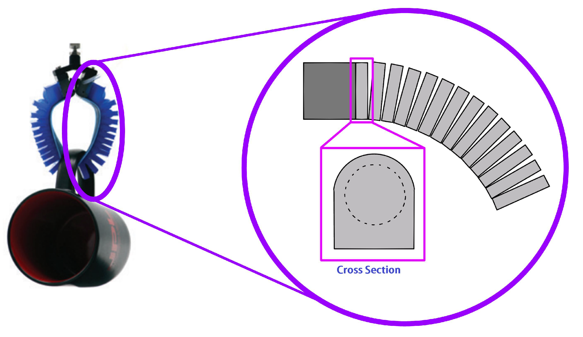
Deformable grippersIn contrast to the two previously mentioned mechanisms, this one cannot exert large amounts of force. This could be an advantage or a disadvantage, depending on the application. However, being flexible, they can adapt to all shapes, and their lack of strength is a positive factor when holding fragile objects.They have little carrying capacity, ranging from grams to a few kilograms.By being able to deform, they can twist their fingers backward, giving a much greater range than previous mechanisms. Some of these grippers can hold as much as a pill, up to a soccer ball (between 8 mm and 200 mm).It practically conforms to the contour of the object you want to hold, no matter how irregular it is. this includes amorphous objects, such as rocks or any complicated surface.
Disclaimer/Publisher’s Note: The statements, opinions and data contained in all publications are solely those of the individual author(s) and contributor(s) and not of MDPI and/or the editor(s). MDPI and/or the editor(s) disclaim responsibility for any injury to people or property resulting from any ideas, methods, instructions or products referred to in the content.

