Article

Lightweight Bioinspired Exoskeleton for Wrist Rehabilitation Powered by Twisted and Coiled Artificial Muscles

1
Department of Mechanical, Energy and Management Engineering, University of Calabria, 87036 Rende, Italy
2
Department of Mechanical Engineering, University of Iowa, Iowa City, IA 42242, USA
*
Author to whom correspondence should be addressed.
Robotics 2023, 12(1), 27; https://doi.org/10.3390/robotics12010027
Submission received: 30 December 2022 / Revised: 30 January 2023 / Accepted: 7 February 2023 / Published: 10 February 2023

Abstract

:
Stroke, cerebral palsy, and spinal cord injuries represent the most common leading causes of upper limb impairment. In recent years, rehabilitation robotics has progressed toward developing wearable technologies to promote the portability of assistive devices and to enable home rehabilitation of the upper extremities. However, current wearable technologies mainly rely on electric motors and rigid links or soft pneumatic actuators and are usually bulky and cumbersome. To overcome the limitations of existing technologies, in this paper, a first prototype of a lightweight, ungrounded, soft exoskeleton for wrist rehabilitation powered by soft and flexible carbon fibers-based twisted and coiled artificial muscles (TCAMs) is proposed. The device, which weighs only 0.135 kg, emulates the arrangement and working mechanism of skeletal muscles in the upper extremities and is able to perform wrist flexion/extension and ulnar/radial deviation. The range of motion and the force provided by the exoskeleton is designed through simple kinematic and dynamic theoretical models, while a thermal model is used to design a thermal insulation system for TCAMs during actuation. The device’s ability to perform passive and active-resisted wrist rehabilitation exercises and EMG-based actuation is also demonstrated.

1. Introduction

Strokes, cerebral palsy [1,2,3], and spinal cord injuries [4,5] lead to impairments and disabilities with negative physiological impacts on the activities of daily living (ADLs). In particular, stroke represents one of the most common causes of limb impairment. Over 80% of stroke survivors demonstrate weakness [6], loss of dexterity, spasticity, and pain [7,8,9,10] in their upper limbs [11]. The Heart Disease and Stroke Statistics reported around 0.8 million stroke episodes in the United States [12] in 2019 and 1.6 million cases in Europe [13] in 2015. Costs of around 45.5 billion dollars for the United States and 45 billion euros for the European Union are estimated annually to cover medical expenses related to stroke rehabilitation [12,13]. Part of these costs is related to expensive and time-consuming hospital-based rehabilitation procedures. There is a critical need to develop wearable and inexpensive rehabilitation devices to allow for home rehabilitation [14,15,16,17]. Rehabilitation robotics have made significant progress in the past few decades, proposing robotic devices able to reproduce rehabilitation exercises and help patients gain range of motion (ROM) and strength of upper limbs after a stroke [18,19,20,21].
These active rehabilitation devices can be mainly classified into two groups: end effectors (EE) and EXOskeletons (EXO) [22]. End effectors are attached to the patient at one distal point, and there is no correspondence between the degrees of freedom (DOF) of the device and those of the human body. Due to a single attachment point, providing motion to a single joint at a time is usually challenging. Figure 1a represents a schematic representation of an EE attached to a patient’s arm. For this reason, controlling the position, force, and torque is highly challenging, resulting in uncomfortable motion and uncontrollable loads. However, EE devices are easy to design and can fit a wide range of patients [22,23,24,25,26,27,28,29,30]. On the other hand, EXOskeletons are characterized by many attachment points, providing the same DOF as human joints with broader ROM compared to EE. In this case, there is a correspondence between biological joints and device joints, and the device can provide fine anthropomorphic motion and wide ROM compared to EEs. However, their design is more complex, less adaptable, and more customizable than the EE [24,25,26,27,28,29,30,31,32]. Due to the presence of many joints, EXO devices provide better control motion [29] compared to EE. Among the EXOs, further classification is possible considering structural connections between the patient and an external frame. When the EXO is linked to an external frame, it is called grounded [33]; otherwise, it is called ungrounded. Figure 1b shows a grounded EXO, while Figure 1c represents an ungrounded EXO.
Over time, many passive and active assist EXO devices have been developed to assist and aid the wrist in recovering mobility during rehabilitation [34,35]. Passive-assist devices provide motion to all the joints while the user does not provide any active muscle contraction. On the other hand, active-assist devices assist the users with “extra strength” while they are actively performing a rehabilitation exercise, by compensating for muscular/joint weakness.
In 2012, Pehilvan et al. developed “Rice Wrist-S” for wrist rehabilitation after spinal cord injury and stroke [36]. Rice Wrist-S is a grounded EXO device with one DOF for forearm supination/pronation and two DC motor-actuated active DOFs for wrist flexion/extension (F/E) and ulnar/radial deviation (U/R). It is composed of a serial mechanism of revolute joints. The ROM device can provide wrist F/E and U/R deviation of 120 and 70 , respectively. The patient grips a handle that is coupled through a linear joint at the device end to prevent misalignments of the device joints. Higher torque output, increased ROM, and low cost due to a serial mechanism instead of a DC motor are some of the pros of this Rice Wrist-S.
In 2013, Martinez et al. [37] developed the “Wrist Gimbal,” a 3-DOF device for wrist and forearm rehabilitation. This grounded device has a serial kinematic configuration of three revolute joints as Rice Wrist-S. The frame mainly comprises 3D-printed ABSplus (Acrylonitrile, Butadiene, and Styrene) components and aluminum bars to reach a sturdy but lightweight structure. Three DC motors power the device for each three-active DOF, and the moment is delivered to the handle through cable drive systems. The ROM is 180 for wrist F/E and 60 for U/R. The wrist gimbal includes a grasping handle for the user’s convenience. Pro: significant ROM makes this device outstanding among other wrist rehabilitation devices. The use of heavy-geared DC motors is a notable con of this device.
In 2014, French et al. [38] presented “MAHI EXO-II,” a grounded robotic exoskeleton for upper limb rehabilitation. The device offers four active DOFs wrist: F/E, U/R, forearm supination/pronation (S/P), and elbow flexion/extension, with shoulder abduction/adduction (Ab/Ad) as passive DOF. The passive DOF aims for better user comfort. The frame is composed of revolute joints for the elbow and forearm, while the wrist structure involves a parallel mechanism of revolute–prismatic–spherical joints. A handle is placed at the end for the patient’s grasping. A DC motor actuates each DOF except for the wrist module, which needs three DC motors. In addition, the transmission is delivered through cable systems and capstans. The wrist range of motion provided is 65 and 63 for the wrist F/E and U/R. Pros: workspace, total torque output, and bandwidth match human capabilities. Cons: conventional actuators make the system complex and bulky and hence require a complex control system.
In 2017, Pezent et al. developed “MAHI OpenWrist” [39], an evolution of Rice Wrist-S. It has been designed to work with the ReNeu Maestro hand exoskeleton module in the combined READAPT device for hand–wrist rehabilitation. OpenWrist, as Rice Wrist-S, is a grounded EXO-device involving the same DOFs with a wide ROM of 135 for F/E and 75 U/R. The structure is composed of a serial mechanism of revolute joint, and the actuation system employs brushed DC motors and cables. Conventional DC motors make the device heavier, which can be classified as a drawback.
Yin-Yu Su et al. [40] presented a 3-DOF grounded wrist rehabilitation robot in 2019. This device performs flexion/extension ( 70 ~ 70 ), ulnar/radial deviation ( 50 ~ 50 ), and forearm supination/pronation ( 75 ~ 75 ) as active ROM. The device consists of revolute joints and a passive spherical mechanism to adjust the device upon user measurements [40]. The device is designed to accurately control the force and stiffness; hence, series elastic actuators (SEA) were attached to the stepper motors. Pros: lightweight, compact device. Cons: passive joint could be misaligned for patients with larger forearms.
POWROBOT is a 3-DOF grounded wrist rehabilitation device proposed in 2022 by Mayetin and Kucuk [41], which can perform wrist flexion/extension, ulnar/radial deviation, and forearm supination/pronation in ranges of ( 80 ~ 80 ), ( 30 ~ 30 ), and ( 80 ~ 80 ), respectively. Three geared motors actuate the rehabilitation robot. Pros: this is a portable device, easily manufacturable, and low-cost for materials and control systems. Cons: ROM is slightly less than existing devices yet sufficient for rehabilitation exercises.
Goncalves et al. [42] proposed a grounded, single-DOF servo motor-operated wrist rehabilitation device in 2020. It has an active joint for flexion/extension motion. Due to the nature of its design, the remaining two passive motions make it a 3-DOF device. The ROM for each motion is as follows: wrist flexion/extension ( 85 ~ 85 ), ulnar/radial deviation ( 15 ~ 55 ), forearm supination/pronation ( 90 ~ 85 ). Pros: user-friendly (due to the controller interface), low-cost, and easily operatable device. Cons: it has a limited ROM for passive DOF.
In 2019, Zhang et al. [43] developed the PWRR wearable wrist rehabilitation robot, which has two DOFs ranging ( 65 ~ 65 ) flexion/extension and ( 80 ~ 25 ) ulnar/radial deviation. The grounded device consists of universal joints actuated by two pneumatic actuators. Xu et al. developed the wrist rehabilitation device (WReD) [44] in 2018, consisting of two DOF passive revolute joints. Only a single DC motor is used in this grounded wrist rehabilitation device. The ROM of flexion/extension is ( 90 ~ 90 ), and ulnar/radial deviation is ( 90 ~ 90 ). Pros: this device is compact, conveniently wearable, and flexible compared to other parallel devices. Cons: the overall system is bulky.
A cable-driven 3-DOF wrist rehabilitation robot: SEU was developed by Ke Shi et al. in 2020 with the ROM of flexion/extension ( 40 ~ 40 ), ulnar/radial deviation ( 75 ~ 75 ), forearm supination/pronation ( 90 ~ 90 ) [45]. This is a ground device and is bulky due to its construction. Each passive motion was actuated using Bowden cables connected to the DC motor via MR clutches for each cable. Pros: better safety, high force, larger workspace than cable-driven systems. Cons: certain characteristics of cables make them less convenient to use in the clinical environment.
A lightweight shape memory alloy (SMA)-based wearable robot, named “Soft Wrist Assist (SWA),” was proposed by Jeong et al. [46] in 2019. It is a 2-DOF device for wrist F/E and U/R. The ungrounded device provides high portability and compliance for better patient comfort and consists of a wearable fingerless glove and a wearable strap. The glove is worn on the hand, while the strap is placed on the forearm. The actuation system consists of five muscle-like actuators (SMA coil springs). Three of these actuators are placed over the back of the hand, and the remaining two are over the palm. The actuators are activated via joule heating and are cooled down with water using a pump for the water motion. The ROM provided is 33.8, 30.4, 15.4, and 21.4 degrees for flexion, extension, ulnar, and radial deviation, respectively (64.2 and 36.9 degrees for the 2-DOF). The device weighs 0.151 kg for the wearable part, but the pump and radiator weigh up to around 1 kg. Pros: this is a flexible, lightweight, easier-to-wear device. Cons: certain components of the device tend to dislocate despite the anchors; in addition, the device is not flexible enough for people with larger forearms.
A pneumatic soft artificial muscle-actuated parallel wrist rehabilitation robot developed by Wang et al. in 2021 [47] is a grounded 3-DOF device. The ROM for each motion is as follows: wrist flexion/extension ( 73 ~ 71 ), ulnar/radial deviation ( 19 ~ 33 ), forearm supination/pronation ( 71 ~ 86 ). Six linear actuators have been developed using pneumatic artificial muscles (PAM), and a stepper motor is available for central motions. Pros: this is a high degree of flexibility, adaptability, safety, and mobility due to the use of soft actuators compared to the existing rehabilitation devices. Cons: the control system needs to be updated from an open-loop system to a closed-loop one for better safety from a control perspective.
Table 1 highlights the characteristics of the devices mentioned above and compares them with the wrist’s biological performances during daily living activities [48]. The actuation system mainly consists of electric motors and cable systems, except for SWA, which uses SMA as actuators. The weight for the electric motor-based device is not available, but the motor’s load requires a grounded device. As a result, the device’s portability is reduced. SWA using SMA-based artificial muscles represents a lightweight device with higher portability than the others. On the other hand, electric motors allow for broader ROM.
In this work, a new exoskeleton for wrist rehabilitation is proposed. It is powered by twisted and coiled artificial muscles (TCAMs), and therefore, in the following, it will be identified with the acronym “TCAMs-Exo.” The new exoskeleton is a 2-DOF, soft, wearable, ungrounded, and lightweight exoskeleton powered by the recently introduced [49], low-cost twisted and coiled artificial muscles made with carbon fibers in silicone rubber (CF/SR). CF/SR TCAMs are very promising actuators that can lift to 12,600 their weight and provide tensile strokes and specific work up to 25% and 758 J/kg, respectively, with less than 0.2 V/cm of input voltage. TCAMs-Exo can monitor passive movements and perform resisted-active motions, and it can provide a ROM for wrist flexion/extension and ulnar/radial deviation of 130 and 79 degrees, respectively. The wearable parts of the device weigh about a tenth of a kilogram. An elastic arm sleeve is used to avoid direct contact between the TCAMs and the user’s skin. To measure the device rotation angles and the user’s intention, inertial measurement units (IMU) [50,51] and EMG electrodes [52] are used as feedback sensors, respectively, while a thermal camera is used to measure the real-time temperature of each TCAM. The user inputs from either IMU or EMG is feedback to the 1 adaptive controller [53,54], which was implemented to control TCAMs robustly. The fabrication cost of the device is relatively inexpensive, with an overall materials cost of around USD 10.
All the existing rehabilitation devices for wrist rehabilitation mainly rely on electric motors, pneumatic actuators, or shape memory alloys as actuators (see Table 1). The novelty of our solution relies on the use of TCAMs, that compared to the actuators mentioned above, present several advantages: contrary to electric motors and pneumatic actuators, TCAMs do not need heavy and noisy power sources to be actuated, and they overcome the limitations of shape memory alloys in terms of cost and hysteretic behavior.
The paper is organized as follows. In Section 2, we present the mathematical background of the TCAMs-Exo design. Section 3 describes the thermal model for the insulation of the TCAMs. Section 4 presents the results on the device manufacturing and experimental testing setup. In Section 5, the experimental performances of our TCAMs-Exo are described and discussed. Finally, in Section 6, we draw our conclusions.

2. TCAMs-Exo Design

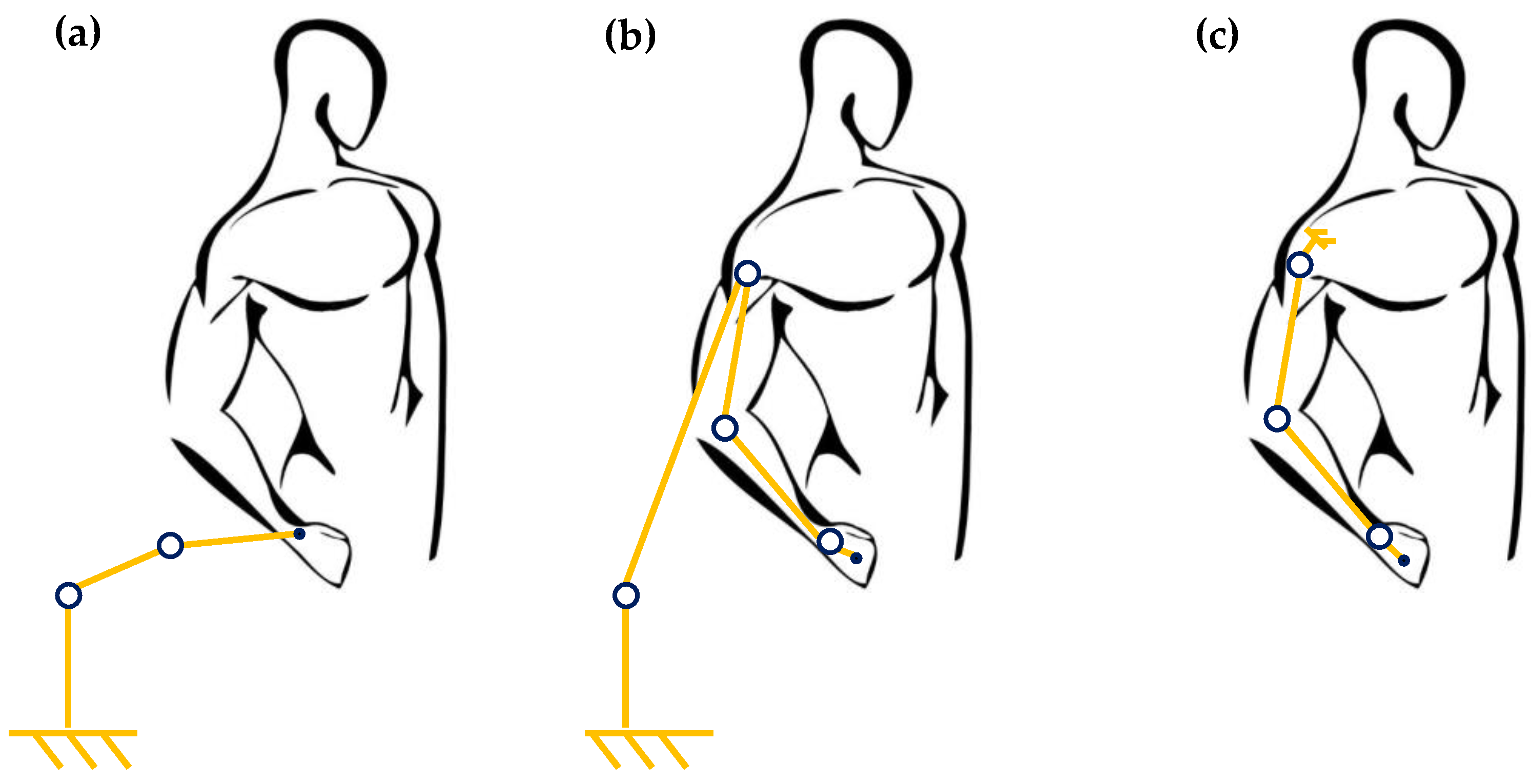
2.1. Bioinspired Design

In the present paper, only two DOFs are considered for the wrists: flexion extension and ulnar/radial deviation (see Figure 2). As in the literature papers mentioned above and listed in Table 1, the pronation/supination DOF involving joints from the forearm is not considered. Flexion and extension movements describe the movement of bending the palm down toward the wrist and raising the hand’s back, respectively. Ulnar deviation, otherwise known as ulnar flexion, is the bending of the wrist to the little finger, or ulnar bone, side. Radial deviation, otherwise known as radial flexion, is the movement of bending the wrist to the thumb, or radial bone, side [55]. As illustrated in Figure 2, θ will indicate the wrist flexion and extension rotation angles, while β will indicate radial and ulnar deviation rotation angles. Figure 2 depicts the skeletal muscles involved in the respective wrist motions.
The extension motion is produced by the Extensor Carpi Ulnaris (ECU) muscle (Figure 2a), the Extensor Carpi Radialis Longus muscle (ECRL) (Figure 2b), and the Extensor Carpi Radialis Brevis muscle (ECRB) (Figure 2c). The flexion motion is produced by the Flexor Carpi Ulnaris muscle (FCU) (Figure 2d), Flexor Carpi Radialis muscle (FCR) (Figure 2e), and Palmaris Longus muscle (PL) (Figure 2f) [56]. FCU and ECU muscles produce ulnar deviation, and ECRL and FCR produce radial deviation. However, the ECRB muscle is activated even during radial deviation. All the muscles and tendons located in the forearm [57] are attached to the hand and elbow.
Figure 2. Muscles mainly involved in the wrist rotations: (a) Extensor Carpi Ulnaris; (b). Extensor Carpi Radialis Longus; (c) Extensor Carpi Radialis Brevis; (d) Flexor Carpi Ulnaris; (e) Flexor Carpi Radialis; (f) Palmaris Longus. (Adapted from Kenhub [58]).
Robotics 12 00027 g002
Natural muscles are capable of performing wide ROMs (see Table 1) due to their mechanical performances, arrangement, and attachment points to the skeletal system. Flexion/extension and adduction/abduction can be reproduced with fidelity by mimicking the arrangement of natural skeletal muscles using artificial muscles [59]. Mechanical performances, compact size, and flexibility of CF/SR TCAMs [49] make this type of artificial muscle particularly suitable for performing this task. TCAMs lend themselves to designing and realizing, in a straightforward way, a bioinspired exoskeleton with human-like features and performance to mimic the behavior of natural muscles. Figure 3a illustrates a schematic representation of the device proposed by the authors. It consists of two non-deformable links (NDL) attached to eight thermally insulated TCAMs. The two NDLs fastened around the hand and the forearm, respectively, house the attachments (screws and nuts) for the TCAMs. The eight artificial muscles have the task of replacing, if necessary, even completely, the action performed by the six skeletal muscles of Figure 2.
The flexion motion is produced by the Flexor TCAMs (F1 and F2), the radial TCAMs (R1 and R2) produce radial deviation, and the ulnar TCAMS (U1 and U2) produce radial deviation. The extension motion is made by the extensor TCAMs (E1 and E2) (Figure 3b). To guarantee user safety, an adequate distance between the skin and TCAMs must be considered. To this aim, a sleeve covers the human body, and the artificial muscles are thermally insulated.

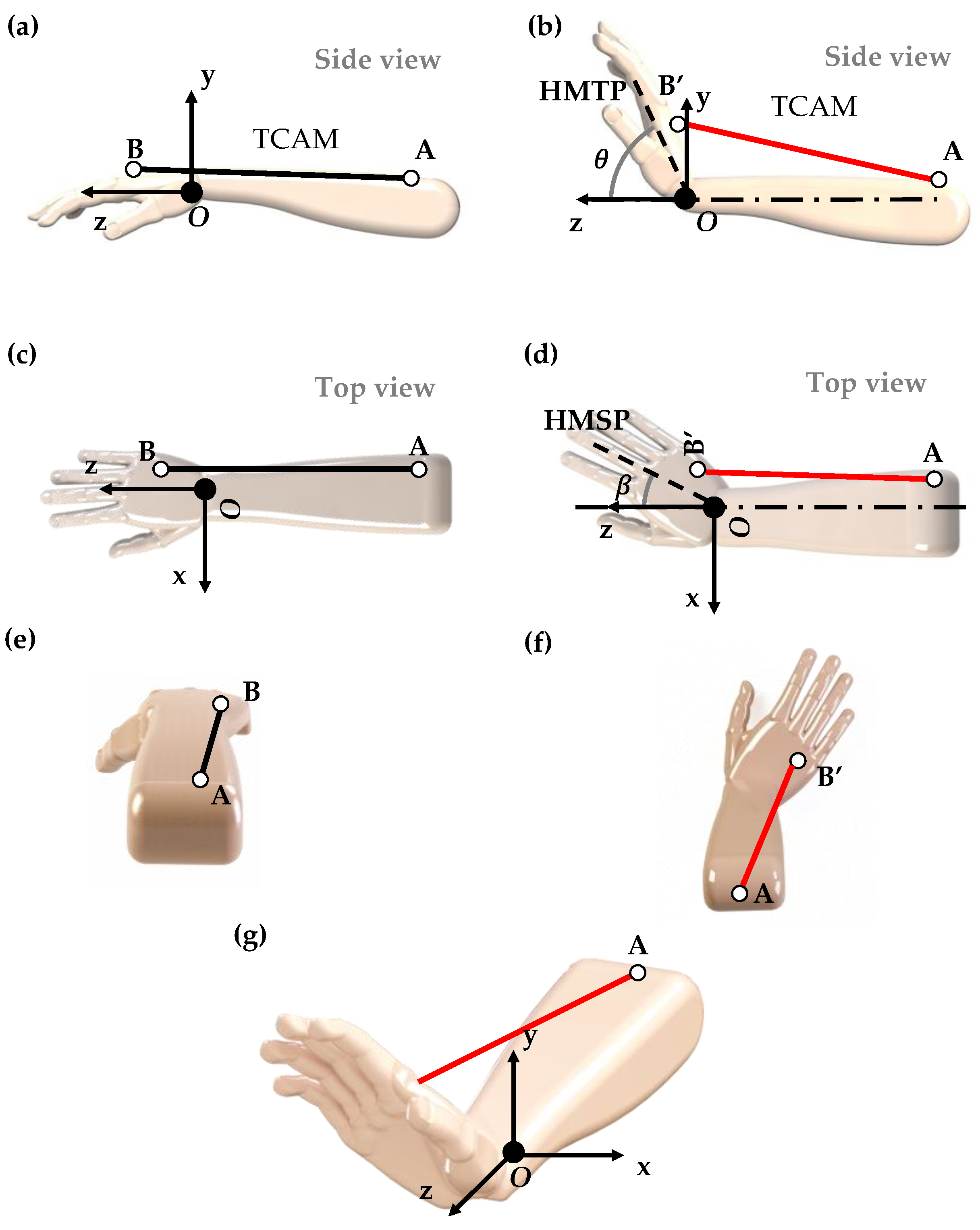
2.2. Geometrical and Biomechanical Considerations

How to perform wrist rotations is a problem that nature has already solved. As depicted in Figure 2, the six muscles are attached to the skeletal system on the hand and forearm through the tendons. In particular, the attachment points are below the fingers and are close to the elbow. By analogy, the attachments of TCAMs are allocated near the same positions and are attached to NDLs, which perfectly adhere to the hand and the forearm (below the elbow).
The biological muscle efficiency in wrist motion can be attributed to the geometrical disposition of the skeletal muscles. The skeletal muscles cover the skeletal system but are close to the hand middle planes, resulting in high rotation with short contraction. This configuration allows for performing the wide ROM provided by skeletal muscles (see Table 1). In addition, the contraction capability of the biological muscles makes the wrist ROM challenging to emulate. Then, bio-inspiration is a reasonable solution to design a device that can perform human wrist motions as closely as possible.
However, an exoskeleton can be placed over the skin instead of being attached directly to the skeletal system. This produces a less efficient system due to the increase in the moment arm. The broader distance between the artificial muscle attachment points and the skeletal system results in the more significant muscle contraction required. To avoid this issue, artificial muscles must be placed close to the skeletal muscle middle planes. To set the muscles as close as possible to the median plane, it is necessary to move the flexor and extensor muscles to the hand sides as close as possible to the hand top plane. In addition, a couple of muscles are used for each motion to provide just one rotation and to avoid secondary bending (combinations of extension/flexion with ulnar/radial deviation). The couple is composed of two muscles, one for each side. The same considerations for the deviations, where the muscles, instead of being placed on the sides, are placed on the top and bottom of the hand as close as possible to the hand side plane. Thus, a couple of muscles are used for each motion, with an overall amount of eight muscles. The muscles are attached to the two NDLs, which emulate the biological muscle’s attachment points.

2.3. TCAMs Contraction and ROM

Kinematic analysis was carried out to evaluate the relationships between artificial muscles contraction and wrist rotations. In Figure 4a, a schematic representation of the hand kinematic is illustrated. Consider a coordinate system o x y z with the origin o in the center of the plane containing the wrist joint and the axis z oriented along the forearm axis (Figure 4g). The two axes x and y identify the axes of rotation of the joint in the plane y z (flexion/extension movements) and x z   (adduction/abduction movements), respectively. For simplicity, this first analysis considers just one TCAM. The generic muscle is attached between the points A and B on the hand and the forearm NDL, respectively, with its longitudinal axis parallel to z axes to any distance from this last.
When the TCAM is not activated (cold status), the hand is in the resting position (see Figure 4a for the side view, Figure 4c for the top view, and Figure 4e for the isometric view, where TCAMs are represented in black line). When the TCAM is activated (heated status), it contracts and the hand rotates, point B assumes the position B , (see Figure 4b for the side view, Figure 4d for the top view, and Figure 4f for the isometric view, where contracted TCAMs are represented in red line). The rotation of the hand in the space can be considered as the combination of two rigid movements, a rotation of θ (between hand middle side plane (HMSP) and z axis) along the x axis in the plane z y (extension), and a rotation of β (between hand middle top plane (HMTP) and z axis) along the y axis, in the plane z x (ulnar deviation).
When there is only a single TCAM present, one muscle provides two rotations at the same time (Figure 4g), which will challenge to generate the user-desired motion at any given moment. The use of a geometric symmetric solution allows for overcoming this challenge.

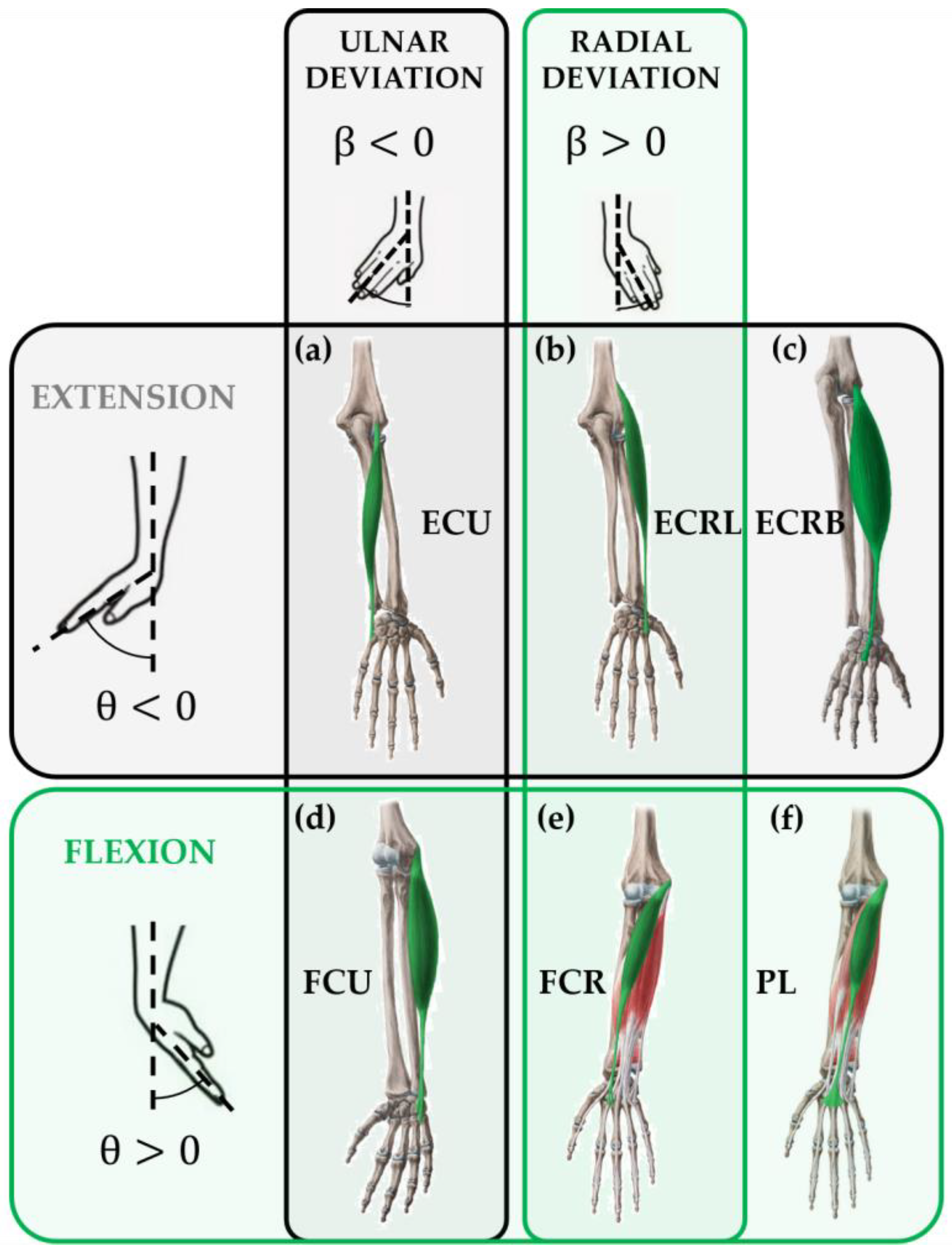
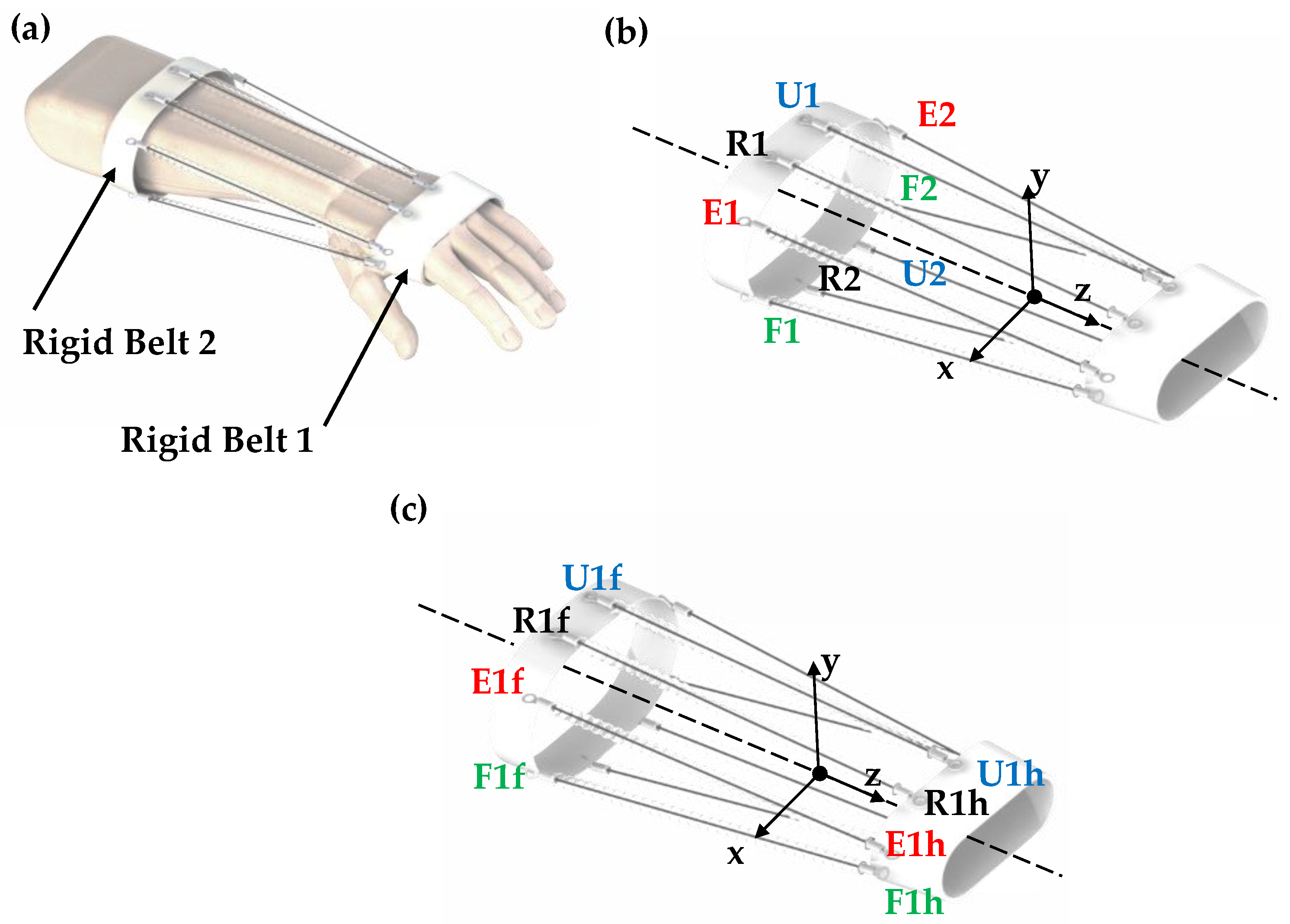
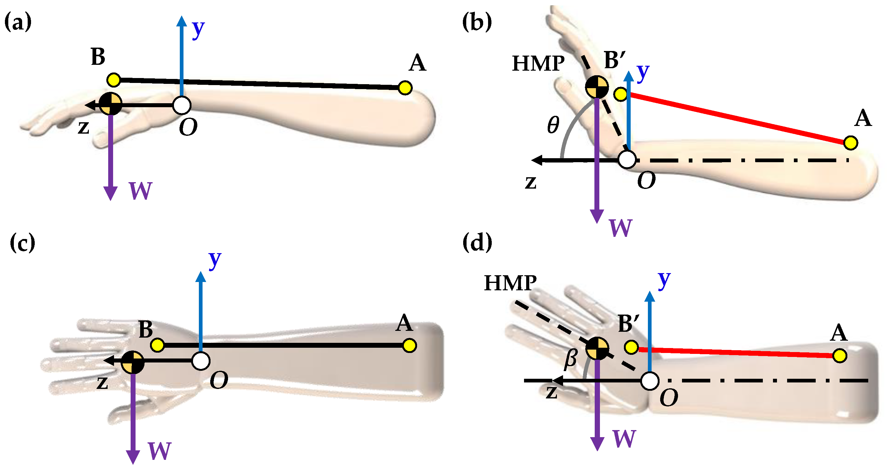
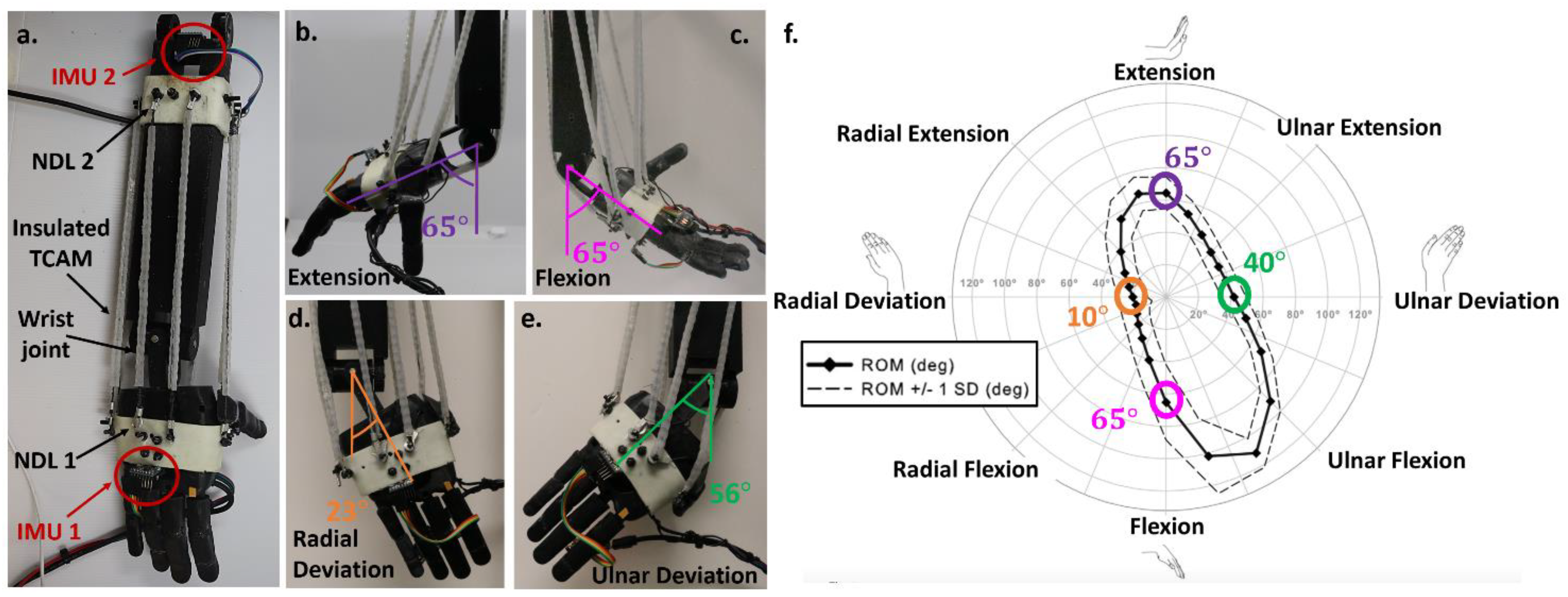
2.4. Extensional and Flexional Motions

Consider the configuration with two equal muscles placed symmetrically around the z y plane (thumb side and little thing side) close to the back of the hand. Then, the contraction of the muscle located on the side opposed to the thumb will produce extension and ulnar deviation motions, while the second one located on the same side of the thumb will produce extension and radial deviation motion. If the electric input is the same for both TCAMs, then the number of movements are the same, with ulnar deviation and radial deviation in opposition. Consequently, the contemporary use of two muscles placed symmetrically and parallel to each other on the palm (or back) allow for obtaining only the extension (or flexion). Figure 5a shows the disposition of the final muscle disposition for extension (on the back) and flexion (on the palm). Whatever the disposition, TCAMs can only contract on a plane parallel to the z y plane. The contraction that must be imposed on the muscles to obtain the desired angle θ of flexion or extension depends on the initial coordinates of the attachments A ( x A ,   y A ,   z A ) and B ( x B ,   y B ,   z B ) and on the final coordinates of the attachment B   ( x B ,   y B ,   z B ) . In the resting position, when θ = 0 , the length of the muscles is L A B and the length of the muscle while under activation is L A B as shown in Equations (1) and (2).
L A B   = ( x B x A ) 2 + ( y B y A ) 2 + ( z B z A ) 2 ,
L A B   = ( x B x A ) 2 + ( y B y A ) 2 + ( z B z A ) 2 .
Then, the contraction c is:
c   = ( L A B   L A B   L A B   ) 100 ,
and considering that the coordinates of the point B change from the coordinate frame B ( x B ,   y B ,   z B ) to B   ( x B ,   y B ,   z B ) according to the rotation matrix R ( θ , β ) :
[ x B y B z B ]   = [ cos β 0 sin β sin β sin θ cos θ cos β sin θ sin β cos θ sin θ c o s β   c o s θ ] R ( θ , β ) [ x B y B z B ]   .
When β   = 0, substituting Equation (4) to Equation (2) provides the extension (or flexion) C F / E = f ( A ( x A ,   y A ,   z A ) ,   B ( x B ,   y B ,   z B ) ,   θ ) as
C F / E = ( ( x B x A ) 2 + ( y B cos θ z B sin θ y A ) 2 + ( y B sin θ z B cos θ z A ) 2 ( x B x A ) 2 + ( y B y A ) 2 + ( z B z A ) 2 1 ) 100 .
It is intuitive to think that larger muscle contraction provides larger ROM (for both flexion and extension). The ROM amplitude depends on the distance between the TCAM attachments on the NDLs and the center of the joint. Smaller distance results in greater amplification. Thus, to obtain a high value of ROM (for flexion and extension) with little contractions, it is very convenient to choose the muscle attachments far from the z y plane (on the hand sides). In addition, the coordinates y A and y B are very low, as close as possible to the hand midplane (HMP).
Figure 5. Schematic representation of the kinematic of the actuation principle of the hand. The muscles are attached to the bands placed on the hand and close to the elbow: (a) extensional/flexional attachments; (b) ulnar and radial deviations attachments; (c) length considered for the design.
Robotics 12 00027 g005

2.5. Ulnar and Radial Deviation Motions

Following the same principle mentioned above, consider two equal muscles placed symmetrically around the z x plane, and if both are, for example, on the portion of the x z plane opposite to the thumb, but one is on the back and the other on the palm side, then the first TCAM will produce extension and ulnar deviation motion while the second one will produce flexion and ulnar deviation motion. With this configuration, the same electric input results with the same amount of motion, with flexion and extension in opposition. As a consequence, the contemporary use of two muscles allows for obtaining only ulnar deviation (or if the two muscles are on the portion of the plane z x near the thumb, only radial deviation). Figure 5b depicts the configuration for ulnar (little finger side) and radial deviation (thumb side). Figure 5c shows the lengths considered for hand and forearm length calculations.
Considering these muscles’ dispositions, then the contraction required to the muscles to obtain the desired angle β for radial or ulnar motion depends, similarly, to the case studied previously on the coordinates of the points A ,   B and B . Contraction C U / R = f ( A ( x A ,   y A ,   z A ) ,   B ( x B ,   y B ,   z B ) ,   θ ) can be shown as:
C U / R = ( ( x B cos β + z B sin β x A ) 2 + ( y B y A ) 2 + ( x B sin β z B cos β z A ) 2 ( x B x A ) 2 + ( y B y A ) 2 + ( z B z A ) 2 1 ) 100 .
Following the same principle used before, the results are convenient to choose the muscles’ attachments as close as possible to the plane z y . Multiple literature studies have reported body segment length and weight. Table 2 reports a summary of both male and female forearm segment length statistics as a percentage of total body length and weight. As mentioned above, the flexion/extension motion and ulnar/radial deviation have been treated separately. However, the simultaneous activation of flexion/extension muscles together with ulnar/radial deviation provides a combined rotation.
Attachment coordinate positions are required to calculate the TCAM contraction percentages, which decide the TCAM lengths. These coordinates depend on the patient’s height. Table 3 presents the attachment coordinates that are a percentage of the patient’s length.

2.6. Load Capacity of TCAMs

The diameter to be attributed to each of the TCAMs of the exoskeleton presented in this paper can be evaluated through a simple load’s static analysis.
The force developed by the muscle during its contraction must be able to counterbalance the weight of the hand in the two worst conditions. The latter can be identified with the wrist extension or flexion from a horizontal start position (see Figure 6a,b) and with ulnar or radial deviation when the hand is in a vertical plane (see Figure 6c,d). In both cases, the figures report just one muscle, but a muscle couple must be considered. The force value can be evaluated by imposing the balance of the moment for the axis of rotation.
According to the configurations depicted in Figure 6, the equilibrium is satisfied by Equation (7):
2 F × O B = W × O C G ,
where F is the force generated by just one muscle, O B is the arm between the origin O and the point B, W is the hand weight, and O C G is the arm between the origin O and the hand center of gravity. The most critical situation arises when the weight force is perpendicular to O B . Figure 6 shows this configuration for both extension and ulnar deviation. Figure 6a,c represents the critical configurations, where the weight W is perpendicular to O B . During rotation, the arm direction changes while gravity keeps the y-direction. The angle between them decreases together with the vectorial product. Figure 6b,d highlights the new configuration after θ and β rotation.
For the analysis, the weight of the hand can be considered concentrated on its center of gravity. The position of the center of gravity, as well as the hand weight, can be deduced from Table 2 once the patient weight and height are known. With dimensions and the weight considered, in the worst condition, the muscle supports around 7 N. Once the force necessary to face the most critical situations has been calculated, the identification of a suitable TCAM can be accomplished. Table 4 presents necessary data for the calculation. All the dimensions listed in the table are suitable for the TCAMs. Then, the choice is based on the handling of the muscle and fabrication process. CF/SR (carbon fiber/silicone rubber) TCAMs are fabricated following the manufacturing process suggested by Lamuta et al. [49]. TCAMs are fabricated by commercial 3K carbon fiber tows (each tow contains 3000 fibers) from ACP composites, mixed with epoxy sizing to hold the fibers. Each CF n-tow is used for each n-bundle TCAM. First, the tows are dipped into a mixture of uncured Silicone Rubber Sylgard 184 Polydimethylsiloxane (PDMS) and are diluted with hexane (the PDMS:hexane weight ratio is 2:1). Hexane is used to decrease the viscosity of the PDMS and to obtain a homogeneous distribution of the PDMS inside the CF tow. After dipping, the CF/PDMS composite is pre-twisted (240 turns/m) using a drill by attaching an external weight. Then, the composite yarn with twisted CF is placed in a dry place to cure PDMS. Once the PDMS is cured, the CF/PDMS composite is twisted further until full. Considering the explained fabrication process, four-bundle (4B) TCAMs provide a good handling and load capacity.
Consider that a 4B TCAM muscle has a diameter of around 1 mm and provides a maximum strength of about 9 MPa, so that it can easily withstand a force of about 7 N. It must be observed that TCAMs are very promising artificial muscles capable of supporting up to 60 MPa of mechanical stress [49].

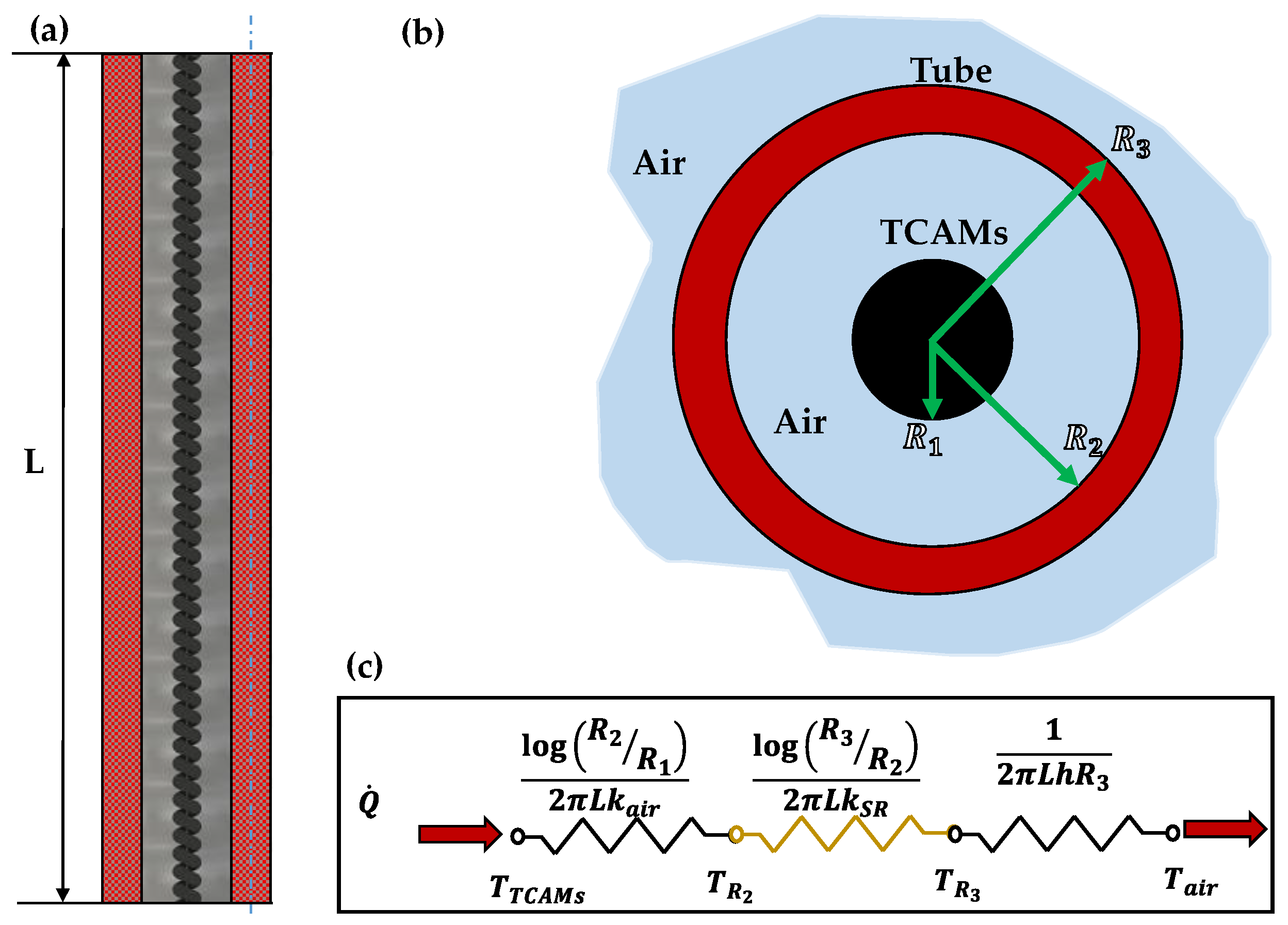
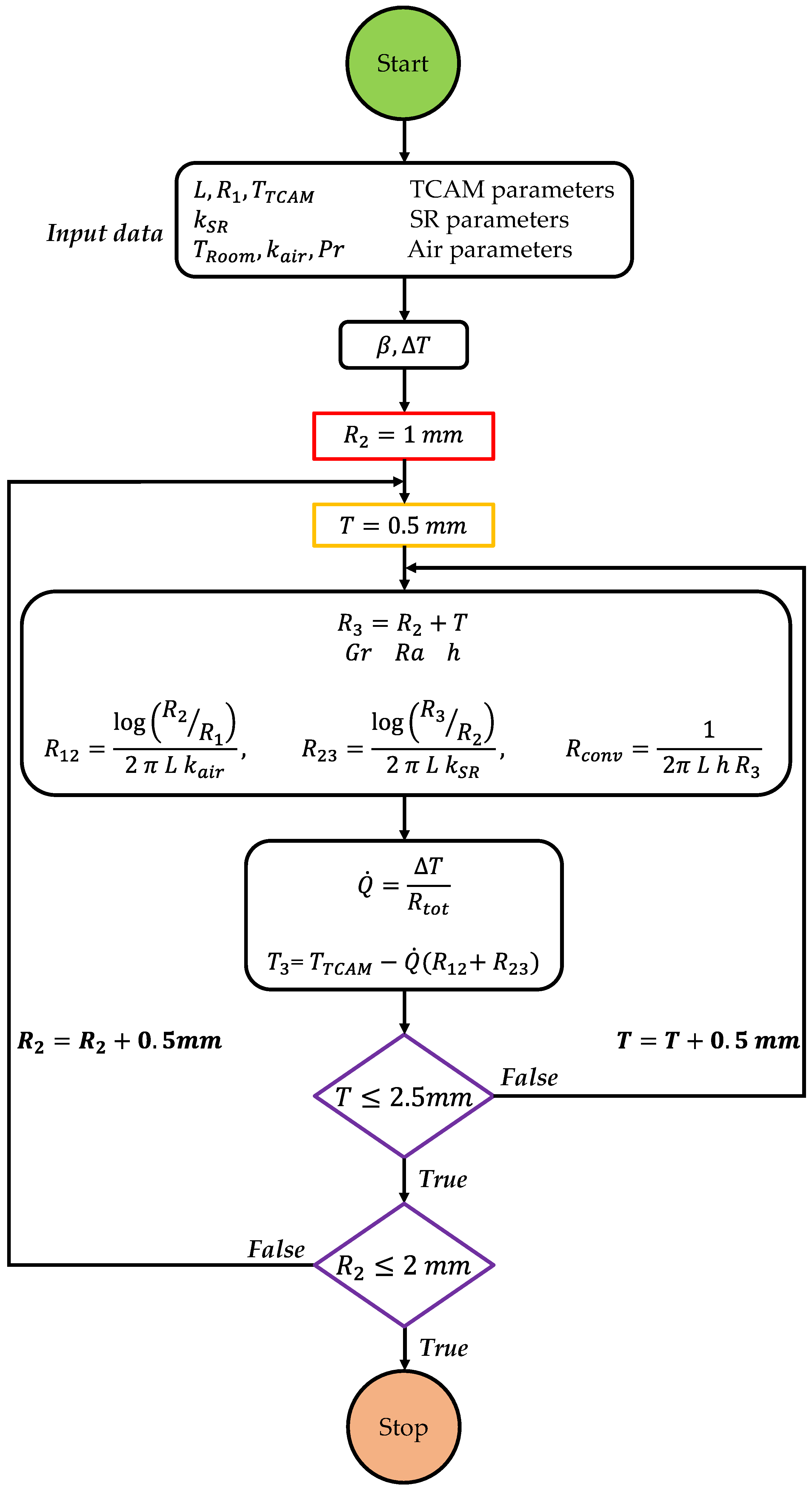
3. Theory of TCAM Insulation Model

The actuation of the TCAMs is based on the heating generated by the passage of current through the carbon fibers. Such heating produces a rise in the temperature of the muscle that can quickly exceed 100   C . The high value of temperature can be very dangerous for the patients, and thus, it becomes very important to protect them by designing a proper thermal insulation system. To this aim, a stretchable polymeric tube surrounding the TCMA seems to represent a good solution. If correctly designed, the tube can satisfy the task of containing the temperature of the muscle and can allow it to contract freely. Between the many possibilities, the silicone rubber seems to satisfy both the thermal and the mechanical requirements. The thickness and the diameter of a tube made with this material can be evaluated by the thermal study of the physical system schematized in Figure 7a, where the TCAM, represented in black, is inside the cylindrical tube, represented in red. Figure 7b shows a cross-section in which R 1 represents the radius of the TCAM, and R 2 and R 3 are the inner and the outer radius of the silicone rubber tube, respectively. The tube is surrounded by air both inside and outside.
The heat produced by the muscle for joule heating can be completely dissipated by passing through the walls of the tube and the layers of air provided; they are well sized. Crossing the insulating path, the temperature decreases by passing from the value of the activated muscle (which, for a contraction values of 5 % , can be assumed, on average, equal to about 105   C ), at the value corresponding to the external air temperature (typically 24   C ). Cooling occurs more or less quickly depending on both the material chosen for the tube and the size of the layers. The thermal power Q ˙ produced by the TCAM is first transferred through the air to the internal surface of the tube, approximatively by a conductive heat transfer mechanism, then by the same mechanism, it is transmitted to the outer surface of the tube, and finally, it is transferred to the outside where the ambient temperature is governing.
By the electrical–thermal analogy, the heat transfer analysis of the thermal system of Figure 7b can be studied through the electrical circuit illustrated in Figure 7c, in which electrical resistance corresponds to thermal resistance, voltage corresponds to temperature difference, and the electrical current corresponds to heat transfer rate. Under steady-state conditions, we have:
Q ˙ = Δ T R t o t .
Thus, if Q ˙ and Δ T are known, the value of R t o t can be computed. It can be shown that R t o t depends on the three variables R 2 ,   R 3 , and T 3 . Therefore, diagrams similar to that reported in Figure 8 can be built, which are very useful for determining an optimized solution. In Figure 8 are plotted the contour lines for a 4B TCAM developing about 1 watt of thermal power, and for the temperatures T 3 , as a function of the tube thickness and the inner tube diameter. A tube of diameter R 2 of 1.75 mm and thickness of 0.5 mm has a predicted temperature of around 51   ° C under steady-state conditions.
The heat exchange between the tube’s outer layer and the air is convection heat transfer. The thermal resistance is the convection resistance of the surface. It can be expressed as
R C o n v = 1 2 π L h R 3 .
The free convective heat transfer coefficient h is calculated based on Equation (10).
h = k a i r 2 R i ( 0.68 + 0.67   R a 2 R i 1 4 ( 1 + ( 0.492 P r ) 9 16   )   4 9 ) ,
where k a i r is the thermal conductivity of the air (0.026 W/m K), R a 2 R i is the Rayleigh number evaluated at 2 R i , with i as the generic radius, and P r is the Prandtl number equal to 0.71 for air [63]. The Rayleigh number is evaluated through the following equation:
R a 2 R i = P r G r 2 R i .
Here, G r 2 R i is the Grashof number evaluated at 2 R i by
G r D i = g   Δ T   β   ( 2 R i ) 3 ν a i r 2 ,
where g is the gravity acceleration (9.81 ms−2), Δ T is the temperature difference between the external surface of the tube and room temperature (24 °C), β is the coefficient of thermal expansion ( 1 T r o o m ) , and ν a i r is the kinematic viscosity of the air ( 1.562 × 10 5   m 2 / s ) . Finally, L is the length of the TCAM (10 mm). All the variables, such as kinematic viscosity and thermal conductivity, are evaluated at room temperature because Grashof and Rayleigh’s numbers are local parameters, and they depend on both the diameter and the operating temperature.
In particular, inside the internal layer of air, for the TCAM operating temperature and the diameter 2 R 2 , the resulting Rayleigh number is in the order of 10 3 , which lies in the range of the conduction regime instead of convection [64]. In addition, the tiny air layer inside the tube seems a reasonable heat exchange regime. In light of what has been mentioned, the thermic resistance governing this layer can be considered a conduction resistance, and therefore:
R C o n d = log R 2 R 1 2 π L k a i r .
Finally, the heat transfer through the wall of the tube is conductive, and the thermal resistance can be expressed as:
R C o n d = log R 3 R 2 2 π L k s r .
Therefore, the total resistance is:
R t o t = 1 2 π L h R 3 + log R 2 R 1 2 π L k a i r + log R 3 R 2 2 π L k s r .
It is preferable to use corrugated tubes shaped like bellows to obtain a better adaptation between the deformation of the walls of the insulating tube and to move the muscles and increase the heat exchange surface. The procedure for designing tubes with this kind of geometry does not differ much from previous ones; however, what was just described can be used with a good approximation. The procedure is shown in the flow chart in Figure 9 . The length of the insulation tube is based on the algorithm described in Figure 9 . This procedure was followed to fabricate the insulation tubes for the TCAMs-Exo prototype.

4. Experimental Setup

To verify the feasibility and functionality of the new wrist rehabilitation system, the authors created a prototype suitable for an adult man weighing 70 kg and at a height of 1.74 m (corresponding to the stature of the first author of the paper). However, using our models, and considering the scalability and ease of manufacturing of TCAMs [65,66], the device can be easily designed for different individuals, with different weights and heights.
For the experimental study, a test bench was equipped with a 3D plastic hand model coupled with a forearm and a TCAM-Exo prototype complete with sensors and all the devices necessary for supplying power and for controlling and measuring the signals. A brief description of the various components will be given below.

4.1. Three-Dimensional Prototype of the TCAM-Exo

In Figure 10a, the two pieces (hand and forearm) making up the artificial right arm used for the experimentation are shown. The arm was made by additive manufacturing. The 3D printer RAISE3D Pro2 Plus dual extruder, by Raise3D (Irvine, CA, USA), was adopted for the fabrication of the two parts in standard PLA (polylactic acid) plastic material. The weight of the printed hand was increased to a human hand weight by using steel disks embedded in the plastic at the center of gravity of the hand (orange plates in the figure). The CAD model was modified according to the purpose of the work. In particular, the wrist joint was replaced with a printed 2-DOF revolute joint able to simulate both wrist motions (for ulnar/radial deviation, see Figure 10b, and for flexion and extension, see Figure 10c). To reduce joint friction, appropriate lubricant was applied. The exoskeleton is composed of eight CF/SR TCAMs with a respective isolating tube, two non-deformable NDLs, two IMU, one sleeve, and surface electromyography (EMG) electrodes (Figure 10a).
The TCAMs were fabricated following the manufacturing process suggested by Lamuta et al. [49]. All the muscles were produced with the same material, the same geometry, and the same number of bundles. The diameter of the generic TCAM was determined through the load analysis, described in the previous section of this paper. For the analysis, the weight and the length of the hand of the patient are provided through Table 2 (70 kg and 1.74 m), and the gravity center and the distance between the muscle and gravity center were determined, as shown in Table 3.
For the more critical conditions, the equation results in a force of 14 N, and Table 4 suggests for this load to use a couple 4B with a diameter of 1 mm. Furthermore, the muscle is oversized and can also be used for hands that are heavier or longer.
The manufacturing process involves the use of commercial 3K carbon fiber tows from ACP composites, mixed with epoxy sizing to hold the fibers. Four CF tows (with an initial length of 0.500 m) were used for each four-bundle TCAM. First, the tows are dipped into a mixture of uncured Silicone Rubber Sylgard 184 PDMS and diluted with hexane (the PDMS:hexane weight ratio is 2:1). Hexane is used to decrease the viscosity of the PDMS and to obtain a homogeneous distribution of the PDMS inside the CF tow. After dipping, the CF/PDMS composite is pre-twisted (240 turns/m) using a drill by attaching an external weight of 0.200 kg. Then, the composite yarn with twisted CF is placed in a dry place to cure PDMS. Once the PDMS is cured, the CF/PDMS composite is twisted (105 turns) further until fully coiled (120 coils). The final length of 0.230 m fully coiled TCAMs were used for the wrist flexion/extension motion generation. The same TCAMs length was used for the wrist ulnar/radial deviation motion.

4.2. The NDL

The NDLs were made by casting a quick-setting urethane elastomer with high resistance to tearing, impact, and wear, in a 3D-printed mold, suitably shaped to the patient’s wrist. The mold is shown in Figure 11. Simpact ™ 85A urethane was found to be stiffer than EcoFlex 00-30 and is thus preferred to it. Simpact ™ urethanes pour easily, and the complete cure time is 48 h at room temperature. However, a release agent was applied to the mold to easily separate the mold and urethane. The TCAMs are connected to the NDLs by standard steel screws and nuts.

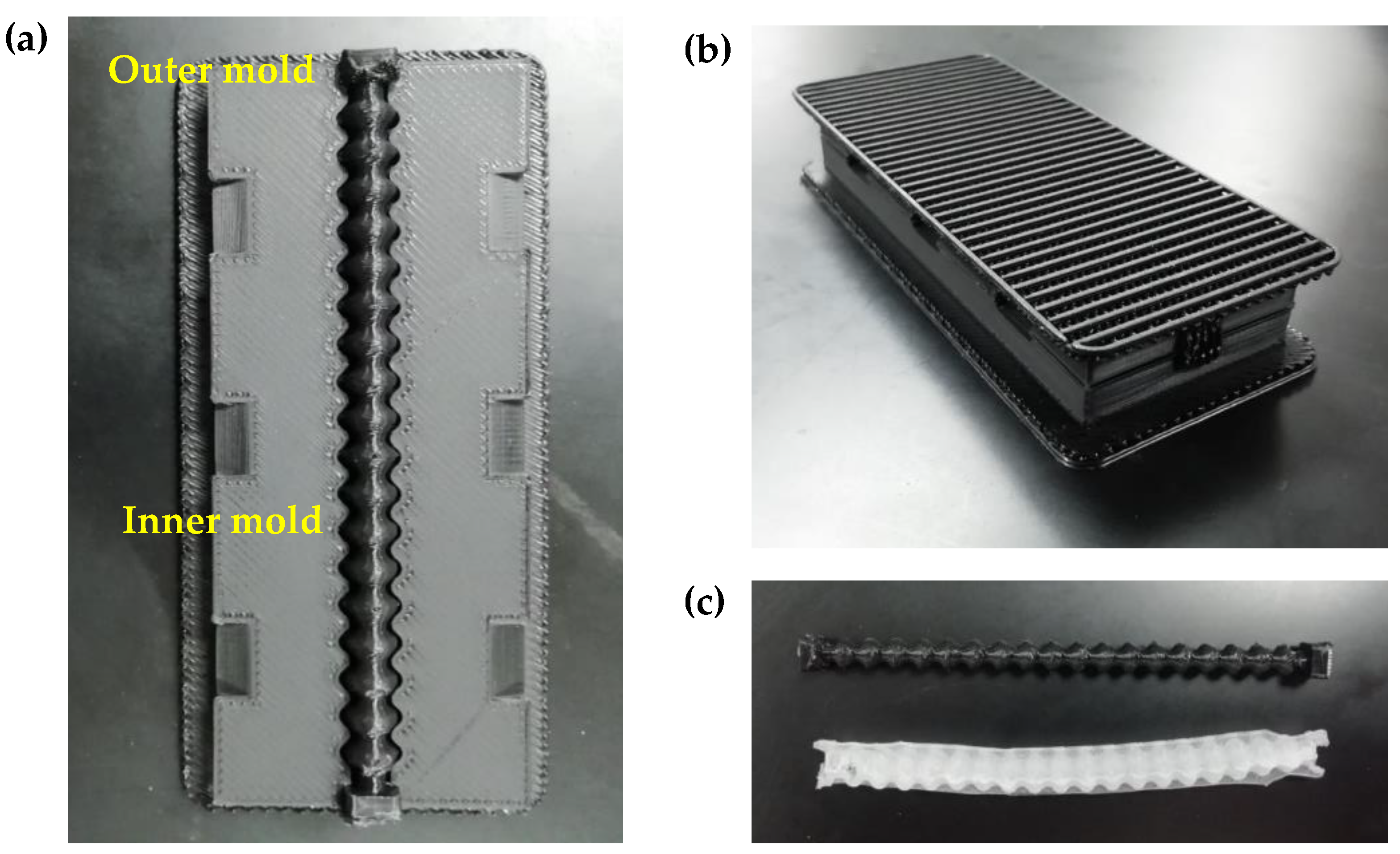
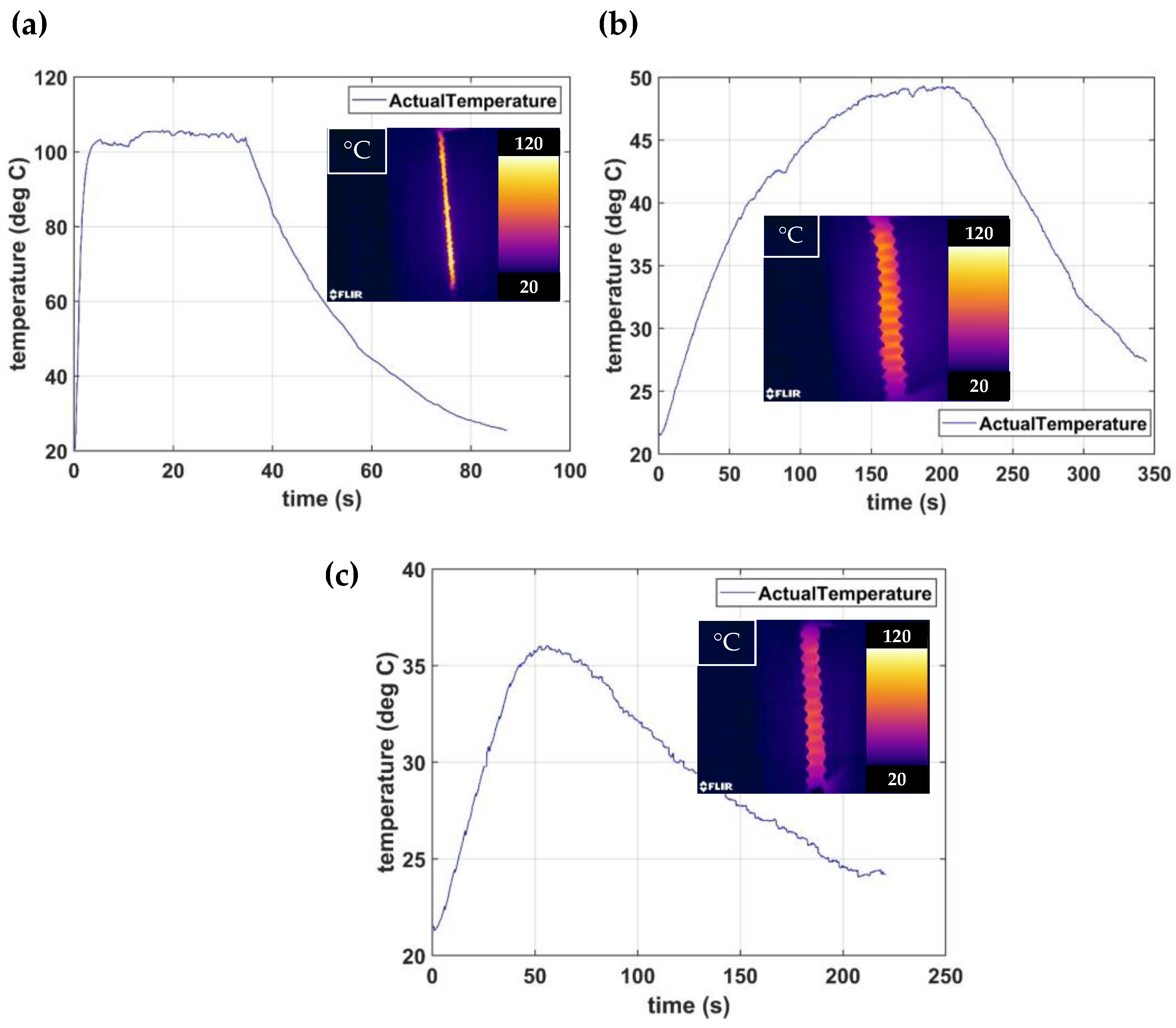
4.3. Thermal Insulating Tubes
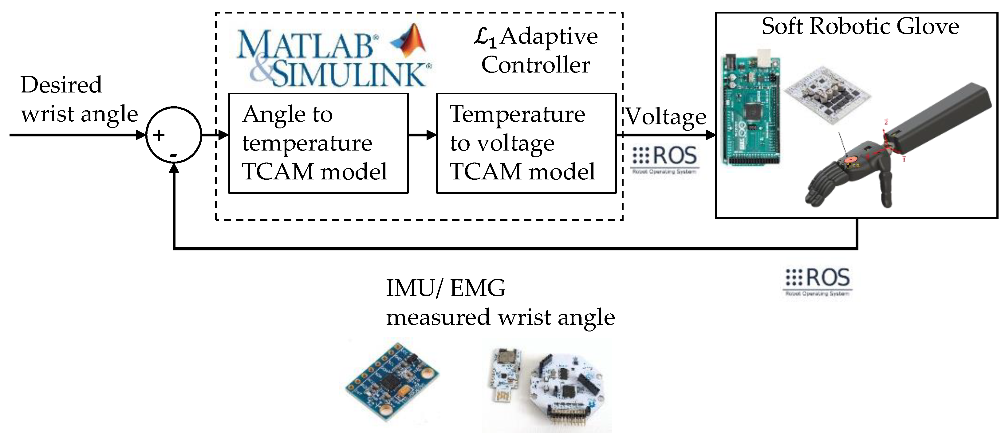
Tubes for thermal insulation were fabricated by casting. The casting molds were designed and 3D printed using standard PLA filament. Figure 12a depicts the printed molds for the fabrication of the insulation tubes. These are fabricated following the manufacturing process suggested by the manufacturer (Smooth-On, Macungie, PA, USA). The EcoFlex 00-30 silicon rubber is mixed with the same amount of A and B components. The prepared silicone rubber mixture is poured inside the mold. Figure 12b shows the molds with the silicone inside during the curing process. After the silicone is cured, it can be ejected from the molds. Figure 12c shows the insulated tubes separated from the mold. The TCAMs, together with the insulation tubes, are attached through two non-deformable bands or NDLs to the arm.

4.4. The 1 Adaptive Controller for Robust Actuation of the TCAMs

In this preliminary version of the device, a controller on the TCAMs actuation has been implemented. The controller is able to provide voltage to each TCAM according to the desired and experimental angle measured via IMUs. The same controller also guarantees device safety by turning off the input voltage when a large actuation angle is measured. Specifically, the robust and adaptive output feedback controller for electro-thermally actuated TCAMs introduced and described in [54] was adopted. The control system algorithm depends on the IMU orientation measurements. The angle between the forearm and the hand is measured using two inertial measurement unit (IMU) sensors (Model: MPU6050, TDK, San Jose, CA, USA), which are placed on the NDLs. They are powered with a sensor for a three-axis accelerometer and three-axis gyroscopes. Real-time data from IMU is essential to rotate the hand toward the desired orientation. Six-degrees-of-freedom IMUs (model: MPU 6050) are used along with microcontrollers (model: Arduino Nano) to acquire position data. The controller is implemented on MATLAB/SIMULINK. The controller sends voltage commands through the ROS (robot operating system) to a microcontroller. ROS is used as the middleware to communicate between the control algorithm and the hardware system. The output voltages to TCAMs are supplied using motor drivers (model: Pololu Dual G2 High-Power Motor Driver 24v18 Shield for Arduino) (Refer Figure 13 soft robotic glove box for the Arduino microcontroller and the Pololu motor drive images).
The complete block diagram of the 1 adaptive controller is shown in Figure 13.
The user-desired input signal is provided by surface EMG electrodes (openBCI Cyton,) which are under the sleeve in contact with human skin. The sensors are placed in the couple over each biological muscle described in the skeletal muscle section. Each couple of EMGs record the voltage along with the muscle. Then, by recording the signal on the six muscles, it is possible to understand which motion is desired.
A common sleeve can be used to avoid direct contact between the muscle and the skin of the patient. The sleeve gives comfort during therapy and protects against any unpleasant contact with hot parts.
A thermal camera (Model: FLIR E95) is used to measure the real-time temperature. The tests were performed below 150 °C temperature to prevent degrading the PDMS [67] at higher temperatures.

5. Results and Discussion

Four different kinds of experimental tests were carried out to verify the functionalities, limits, and potentialities of the exoskeleton. The first three tests were performed by applying the prototype to the artificial arm and the last one was permitted to verify its applicability to a human. In this section, the results of the thermal insulation system assessment are, firstly, illustrated. Next, the limits of applicability in performing passive and active rehabilitation protocols are discussed. Finally, an interesting potentiality of an integrated human machine is presented.

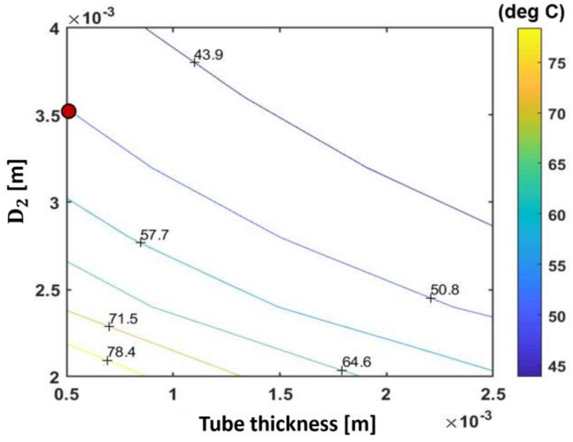
5.1. Thermal Insulation System Assessment

Some tests were carried out to evaluate the effects of the proposed thermal insulation system. Figure 14a shows the variation with the time of the medium temperature, measured by a thermal camera, on the external surface of a TCAM without thermal insulation. TCAM is subjected to a constant contraction of 5%, under an external attached load of 0.2 kg, for about 30 s. The inset shows the temperature profile along the TCAM. It can be observed that high values of temperature, above 100 °C, were registered.
Figure 14b shows the measured outside temperature when a corrugated silicon rubber tube with D 2 = 3.5   mm and a thickness of 0.5 mm is used as a thermal insulating system. The dimensions of the tube were determined on the base of the thermal analysis described in the previous dedicated section and, in particular, by the analysis of the contour lines reported in Figure 8. The solution taken into account is indicated on the graph by a red point. The measured temperature under the steady-state condition (after 3 min) is closer to 49 °C, which is very near to that estimated by the thermal analysis (see Figure 8). The insulation tube has provided more than 50% of temperature reduction in this condition. However, a single repetition of a rehabilitation exercise section is usually quicker than 3 min (see the next section). Figure 14c shows that the temperature decreases to 36 °C during the rehabilitation exercise tested. Therefore, the insulation system is more than suitable for rehabilitation applications such as for a protocol that provides a wrist extension of ± 30 degrees.

5.2. Passive Rehabilitation Exercise

In the passive rehabilitation exercise, the motion is generated just from the device. The wrist rehabilitation protocol suggested by Slutsky et al. [68] and the Summit Medical Group [69] was considered for the experiment. The protocol states to use a dynamic/static splint if the rotations are lower than 30°.
There, contractions of about 8% and 5%, respectively, were imposed to generate extensional/flexional and ulnar/radial deviations as static wrist motions of 30° (Equations (3) and (4)). To generate extensional/flexional movements, the muscles E1/F1 and E2/F2 (Figure 3) were activated simultaneously, while for generating ulnar/radial deviation motions, the simultaneous activation of the muscles R1/U1 and R2/U2 were performed. The angles of the wrist rotation were verified in real time by the couple of IMUs placed on the NDLs. The desired angles for each motion were selected from the work by Crisco et al. [70] in 2011. The prototype well responds to the electric input, even if the targets were not completely achieved, in particular, a range of motion of ± 25°, for wrist extension and flexion, with angles of 23° and 27° for radial and ulnar deviation, respectively.
Although the amplitude of the angles could be increased by raising the level of the electrical input, it was preferred not to force further. High temperatures give rise to problems of a thermal nature, such as the degradation of the polymer. However, the maximum performances were still tested. Such tests are depicted in Figure 15. An angle of 65 degrees was reached for extension and flexion, as shown in Figure 15b,c, respectively. Figure 15d depicts an angle of 23 degrees for radial deviation, and 56 degrees is instead reached for ulnar deviation in Figure 15e. The maximum angles reached for each motion are plotted on the wrist ROM mean value plot in Figure 15f.
The failure to reach the target angles is almost certainly due to the arrangement of the muscles and, in particular, to the accuracy by which the coordinate of the attachment points was replicated on this first prototype. To these errors, which can certainly be eliminated in the next prototype by optimizing the geometry of the attachments, the errors due to the scarce resolution of the angular measurement system adopted must be added (this too is a source of error that can be eliminated).
Further experiments were carried out to verify the possibility of carrying out dynamic passive rehabilitation protocols. For example, the extension is represented by the continuous red curve in Figure 16a (a sinusoidal half-wave lasting about 80 s). In this case, an extensional rotation of the wrist between 0° to 10° is desired, a cycle starting from the resting position (0°), reaching the maximum position (10°) after 40 s and returning to the resting position after about 80 s. To replicate such a movement, a controller is necessary (see the dedicated section) for transforming the desired angle signal in a contraction of the muscles and to compare it with the measured angle (from IMU system). The controller intervenes in case of a mismatch. The blue curve in Figure 16a represents the measured angle versus the time. It can be observed that the measured angle follows well enough the profile of the desired angle, except at the start and end of the stroke, where the system seems to suffer from some inertial delay. The average error measured between the desired and experimental angle for the passive mode rehabilitation exercises shown in Figure 16 is 0.9896   .

5.3. Active Rehabilitation Exercise

After the test campaign for the validation of the prototype in the field of passive rehabilitation, a second test campaign was carried out to validate the prototype for active rehabilitation. In this case, the device has the task of helping the patient who tries to carry out the rehabilitative exercise without succeeding.
To verify the potentiality of the device for active rehabilitation, the action of a patient with a weak wrist was simulated. The experiments were carried out simulating the action of the patient with a weak wrist by using a stepper motor that rotates while pulling a wire attached to the printed hand.
The device is asked to perform the protocol of Figure 16b, (red curve) with the controller deactivated. It tries to perform the desired movement, but it is too weak, and it can raise the hand to 6° and does not go further. The blue curve highlights this behavior. From the graph of Figure 16b, it can be seen the great difference between the measured angle and the desired angle. A second attempt is requested from the simulated patient; this time, the controller is activated at the same time. Figure 16c shows how the controller intervenes to help the patient as soon as the desired rotation is below the measured one. The device allows the patient to perform the imposed work cycle correctly (blue and red curves overlap). The experiment shows the active-assisted motion capability of the device.
Figure 16d,e shows the variation of the velocity measured versus the time for flexion/extension and ulnar/radial deviation, respectively. The speeds measured lie in the range of rotation rates for many individuals [71].
Figure 16f depicts the response of the TCAMs-Exo to a fast cyclic ulnar–radial deviation, which is further evidence of the functionality of the device for passive rehabilitation.

5.4. Human–Machine Interaction

The last experiments were carried out to test the possibility of using the new device on a human patient. Firstly, the active and passive rehabilitation experiments, similar to that carried out on the mannequin arm, were successfully repeated on a human arm. Subsequently, some tests were performed to verify the possibility of making the rehabilitation device interact directly with the patient. The idea is to allow the patient (obviously, in cases where the EMG signals are reliable and the patient does not have total muscular weakness) to directly control the action of the TCAMs-Exo with the electrical signals emitted by their own muscles. These signals can be picked up through typical surface electrodes (EMGs) and transformed into electrical signals able to provide the contraction of the artificial muscles.
With this philosophy, the patient who accuses problems and cannot perform the exercise can control the machine without intermediaries. The picture in Figure 17a shows the human arm wearing the TCAMs-Exo. In the box at the bottom right of the same figure, the arrangement of the electrodes attached on the patient’s arm can be seen. The sleeve covers the electrodes.
Figure 17b shows the control panel of the voltage data of the surface EMG signal. In this case, the voltage plot reflecting the predominant muscles contribute to the wrist extension motion.
Once the input from EMGs is recorded, then the exercise starts. The muscles activated are shown in Figure 17a. Finally, Figure 17c shows the maximum temperature reached during the test, which is lower than 40 °C. Figure 17d,e represents the angle performed during the test (around 10°). The motion follows the path described in Figure 16a. It is clear from Figure 17b that the maximum EMG signal is recorded from the Extensor Carpi Radialis Brevis muscle, mainly responsible for wrist extension. Our algorithm is able to detect the skeletal muscle with the biggest EMG signal and then trigger the actuation of the correspondent TCAM on the device (shown in Figure 17a) to aid the motion performed. This allows the user to then trigger specific TCAMs according to the desired motion.

6. Conclusions

A wearable and lightweight glove for wrist flexion and extension rehabilitation was proposed herein. The device is powered by novel twisted and coiled artificial muscles (TCAMs), able to overcome the limitations of bulky and noisy conventional actuators.
The device, which weighs only 0.135 kg, emulates the arrangement and working mechanism of biological muscles in the upper extremities, and it is able to perform wrist flexion/extension and ulnar/radial deviation of 130 and 79 degrees, respectively.
The range of motion and the force provided by the exoskeleton were designed using simple kinematic and dynamic theoretical models, while a thermal model was used to design a thermal insulation system for TCAMs during actuation and to guarantee the wearer’s safety.
By implementing control algorithms, the device’s ability to perform passive and active-resisted wrist rehabilitation exercises and EMG-based actuation was also demonstrated. Exercises were performed with an average error of only 0.9896 between the desired and experimental angles.
These promising results represent a first step toward the development of lightweight and low-cost TCAM-based human-assistive robotic devices.

Author Contributions

Conceptualization, C.L., V.C. and L.P.; methodology, software, C.G. and V.C.; validation, C.G. and T.H.W.; writing C.G. and T.H.W.; supervision, C.L. and L.P.; funding acquisition, C.L. All authors have read and agreed to the published version of the manuscript.

Funding

This work was supported by DARPA (Young Faculty Award; grant no. W911NF2110344-0011679424) and ONR (grant no. N00014-20-1-2224 and grant no. N00014-22-1-2021); Office of Naval Research: N00014-23-1-2116.

Data Availability Statement

The data presented in this study are available on request from the corresponding author.

Conflicts of Interest

The authors declare no conflict of interest.

References

  1. Krigger, K.W. Cerebral palsy: An overview. Am. Fam. Physician 2006, 73, 91–100. [Google Scholar]
  2. Aisen, M.L.; Kerkovich, D.; Mast, J.; Mulroy, S.; Wren, T.A.L.; Kay, R.M.; Rethlefsen, S.A. Cerebral palsy: Clinical care and neurological rehabilitation. Lancet Neurol. 2011, 10, 844–852. [Google Scholar] [CrossRef]
  3. Øtensjø, S.; Carlberg, E.B.; Vøllestad, N.K. Motor impairments in young children with cerebral palsy: Relationship to gross motor function and everyday activities. Dev. Med. Child Neurol. 2004, 46, 580–589. [Google Scholar] [CrossRef]
  4. Snoek, G.J.; Ijzerman, M.J.; Hermens, H.J.; Maxwell, D.; Biering-Sorensen, F. Survey of the needs of patients with spinal cord injury: Impact and priority for improvement in hand function in tetraplegics. Spinal Cord 2004, 42, 526–532. [Google Scholar] [CrossRef]
  5. Cox, R.J.; Amsters, D.I.; Pershouse, K.J. The need for a multidisciplinary outreach service for people with spinal cord injury living in the community. Clin. Rehabil. 2001, 15, 600–606. [Google Scholar] [CrossRef] [PubMed]
  6. Virani, S.S.; Alonso, A.; Benjamin, E.J.; Bittencourt, M.S.; Callaway, C.W.; Carson, A.P.; Chamberlain, A.M.; Chang, A.R.; Cheng, S.; Delling, F.N.; et al. Heart disease and stroke statistics—2020 update: A report from the American Heart Association. Circulation 2020, 141, e139–e596. [Google Scholar] [CrossRef]
  7. Delph, M.A.; Fischer, S.A.; Gauthier, P.W.; Luna, C.H.M.; Clancy, E.A.; Fischer, G.S. A soft robotic exomusculature glove with integrated sEMG sensing for hand rehabilitation. In Proceedings of the 2013 IEEE 13th International Conference on Rehabilitation Robotics (ICORR), Seattle, WA, USA, 24–26 June 2013; pp. 1–7. [Google Scholar] [CrossRef]
  8. Canning, C.G.; Ada, L.; Adams, R.; O’Dwyer, N.J. Loss of strength contributes more to physical disability after stroke than loss of dexterity. Clin. Rehabil. 2004, 18, 300–308. [Google Scholar] [CrossRef] [PubMed]
  9. Balasubramanian, S. Motor Impairments Following Stroke. 2015. Available online: https://www.researchgate.net/publication/281198195_Motor_impairments_following_stroke (accessed on 18 January 2023).
  10. Raghavan, P. Upper Limb Motor Impairment after Stroke. Phys. Med. Rehabil. Clin. 2015, 26, 599–610. [Google Scholar] [CrossRef]
  11. Wolfe, C.D.A. The Impact of Stroke; British Medical Bulletin: London, UK, 2000; Volume 56, pp. 275–286. [Google Scholar]
  12. Benjamin, E.J.; Muntner, P.; Alonso, A.; Bittencourt, M.S.; Callaway, C.W.; Carson, A.P.; Chamberlain, A.M.; Chang, A.R.; Cheng, S.; Das, S.R.; et al. Heart Disease and Stroke Statistics—2019 Update: A Report From the American Heart Association. Circulation 2019, 139, e56–e528. [Google Scholar] [CrossRef] [PubMed]
  13. Nichols, M.; Townsend, N.; Rayner, M. European cardiovascular disease statistics. Eur. Heart Netw. Eur. Soc. Cardiol. 2012, 1, 10–123. [Google Scholar]
  14. Olsen, T.S. Arm and leg paresis as outcome predictors in stroke rehabilitation. Stroke 1990, 21, 247–251. [Google Scholar] [CrossRef] [Green Version]
  15. Bütefisch, C.; Hummelsheim, H.; Denzler, P.; Mauritz, K.H. Repetitive training of isolated movements improves the outcome of motor rehabilitation of the centrally paretic hand. J. Neurol. Sci. 1995, 130, 59–68. [Google Scholar] [CrossRef] [PubMed]
  16. Carey, J.R.; Kimberley, T.J.; Lewis, S.M.; Auerbach, E.J.; Dorsey, L.; Rundquist, P.; Ugurbil, K. Analysis of fMRI and finger tracking training in subjects with chronic stroke. Brain 2002, 125, 773–788. [Google Scholar] [CrossRef] [PubMed]
  17. Carey, J.R.; Durfee, W.K.; Bhatt, E.; Nagpal, A.; Weinstein, S.A.; Anderson, K.M.; Lewis, S.M. Comparison of finger tracking versus simple movement training via telerehabilitation to alter hand function and cortical reorganization after stroke. Neurorehabil. Neural Repair 2007, 21, 216–232. [Google Scholar] [CrossRef] [PubMed]
  18. Lum, P.; Reinkensmeyer, D.; Mahoney, R.; Rymer, W.Z.; Burgar, C. Robotic devices for movement therapy after stroke: Current status and challenges to clinical acceptance. Top. Stroke Rehabil. 2002, 8, 40–53. [Google Scholar] [CrossRef]
  19. Hu, X.L.; Tong, K.Y.; Song, R.; Zheng, X.J.; Lui, K.H.; Leung, W.W.F.; Ng, S.; Au-Yeung, S.S.Y. Quantitative evaluation of motor functional recovery process in chronic stroke patients during robot-assisted wrist training. J. Electromyogr. Kinesiol. 2009, 19, 639–650. [Google Scholar] [CrossRef]
  20. Volpe, B.T.; Krebs, H.I.; Hogan, N.; Edelstein, L.; Diels, C.; Aisen, M. A novel approach to stroke rehabilitation: Robot-aided sensorimotor stimulation. Neurology 2000, 54, 1938–1944. [Google Scholar] [CrossRef]
  21. Norouzi-Gheidari, N.; Archambault, P.S.; Fung, J. Effects of robot-assisted therapy on stroke rehabilitation in upper limbs: Systematic review and meta-analysis of the literature. J. Rehabil. Res. Dev. 2012, 49, 479–496. [Google Scholar] [CrossRef]
  22. Dombovy, M.L. Emerging therapies in neurorehabilitation. Contin. Lifelong Learn. Neurol. 2011, 17, 530–544. [Google Scholar] [CrossRef]
  23. Fasoli, S.E.; Krebs, H.I.; Stein, J.; Frontera, W.R.; Hogan, N. Effects of robotic therapy on motor impairment and recovery in chronic stroke. Arch. Phys. Med. Rehabil. 2003, 84, 477–482. [Google Scholar] [CrossRef]
  24. Prange, G.B.; Jannink, M.J.A.; Groothuis-Oudshoorn, C.G.M.; Hermens, H.J.; Ijzerman, M.J. Systematic review of the effect of robot-aided therapy on recovery of the hemiparetic arm after stroke. J. Rehabil. Res. Dev. 2006, 43, 171–184. [Google Scholar] [CrossRef] [Green Version]
  25. Brewer, B.R.; McDowell, S.K.; Worthen-Chaudhari, L.C. Poststroke upper extremity rehabilitation: A review of robotic systems and clinical results. Top. Stroke Rehabil. 2007, 14, 22–44. [Google Scholar] [CrossRef]
  26. Maciejasz, P.; Eschweiler, J.; Gerlach-Hahn, K.; Jansen-Troy, A.; Leonhardt, S. A survey on robotic devices for upper limb rehabilitation. J. NeuroEng. Rehabil. 2014, 11, 3. [Google Scholar] [CrossRef]
  27. Mehrholz, J.; Pohl, M. Electromechanical-assisted gait training after stroke: A systematic review comparing end-effector and exoskeleton devices. J. Rehabil. Med. 2012, 44, 193–199. [Google Scholar] [CrossRef]
  28. Chu, C.Y.; Patterson, R.M. Soft robotic devices for hand rehabilitation and assistance: A narrative review. J. NeuroEng. Rehabil. 2018, 15, 9. [Google Scholar] [CrossRef]
  29. Lo, H.S.; Xie, S.Q. Exoskeleton robots for upper-limb rehabilitation: State of the art and future prospects. Med. Eng. Phys. 2012, 34, 261–268. [Google Scholar] [CrossRef]
  30. Molteni, F.; Gasperini, G.; Cannaviello, G.; Guanziroli, E. Exoskeleton and End-Effector Robots for Upper and Lower Limbs Rehabilitation: Narrative Review. PMR 2018, 10, S174–S188. [Google Scholar] [CrossRef]
  31. Aggogeri, F.; Mikolajczyk, T.; O’Kane, J. Robotics for rehabilitation of hand movement in stroke survivors. Adv. Mech. Eng. 2019, 11, 1–14. [Google Scholar] [CrossRef]
  32. Lee, S.H.; Park, G.; Cho, D.Y.; Kim, H.Y.; Lee, J.Y.; Kim, S.; Park, S.B.; Shin, J.H. Comparisons between end-effector and exoskeleton rehabilitation robots regarding upper extremity function among chronic stroke patients with moderate-to-severe upper limb impairment. Sci. Rep. 2020, 10, 1–8. [Google Scholar] [CrossRef]
  33. Piggott, L.; Wagner, S.; Ziat, M. Haptic neurorehabilitation and virtual reality for upper limb paralysis: A review. Crit. Rev. Biomed. Eng. 2016, 44, 1–32. [Google Scholar] [CrossRef]
  34. Gopura, R.A.R.C.; Bandara, D.S.V.; Kiguchi, K.; Mann, G.K.I. Developments in hardware systems of active upper-limb exoskeleton robots: A review. Rob. Auton. Syst. 2016, 75, 203–220. [Google Scholar] [CrossRef]
  35. Hussain, S.; Jamwal, P.K.; Van Vliet, P.; Ghayesh, M.H. State-of-The-Art Robotic Devices for Wrist Rehabilitation: Design and Control Aspects. IEEE Trans. Hum. Mach. Syst. 2020, 50, 361–372. [Google Scholar] [CrossRef]
  36. Pehlivan, A.U.; Lee, S.; O’Malley, M.K. Mechanical design of RiceWrist-S: A forearm-wrist exoskeleton for stroke and spinal cord injury rehabilitation. In Proceedings of the IEEE RAS and EMBS International Conference on Biomedical Robotics and Biomechatronics, Rome, Italy, 24–27 June 2012; pp. 1573–1578. [Google Scholar] [CrossRef]
  37. Martinez, J.A.; Ng, P.; Lu, S.; Campagna, M.S.; Celik, O. Design of Wrist Gimbal: A forearm and wrist exoskeleton for stroke rehabilitation. In Proceedings of the IEEE International Conference on Rehabilitation Robotics, Seattle, WA, USA, 24–26 June 2013. [Google Scholar] [CrossRef]
  38. French, J.A.; Rose, C.G.; O’Malley, M.K. System characterization of MAHI Exo-II: A robotic exoskeleton for upper extremity rehabilitation. In Proceedings of the ASME 2014 Dynamic Systems and Control Conference, San Antonio, TX, USA, 22–24 October 2014; Volume 3. [Google Scholar] [CrossRef]
  39. Pezent, E.; Rose, C.G.; Deshpande, A.D.; O’Malley, M.K. Design and characterization of the OpenWrist: A robotic wrist exoskeleton for coordinated hand-wrist rehabilitation. In Proceedings of the IEEE International Conference on Rehabilitation Robotics, London, UK, 17–20 July 2017; pp. 720–725. [Google Scholar] [CrossRef]
  40. Su, Y.Y.; Yu, Y.L.; Lin, C.H.; Lan, C.C. A compact wrist rehabilitation robot with accurate force/stiffness control and misalignment adaptation. Int. J. Intell. Robot. Appl. 2019, 3, 45–58. [Google Scholar] [CrossRef]
  41. Mayetin, U.; Kucuk, S. Design and Experimental Evaluation of a Low Cost, Portable, 3-DOF Wrist Rehabilitation Robot with High Physical Human–Robot Interaction. J. Intell. Robot. Syst. Theory Appl. 2022, 106, 65. [Google Scholar] [CrossRef]
  42. Gonçalves, R.S.; Brito, L.S.F.; Moraes, L.P.; Carbone, G.; Ceccarelli, M. A fairly simple mechatronic device for training human wrist motion. Int. J. Adv. Robot. Syst. 2020, 17, 1–15. [Google Scholar] [CrossRef]
  43. Zhang, L.; Li, J.; Cui, Y.; Dong, M.; Fang, B.; Zhang, P. Design and performance analysis of a parallel wrist rehabilitation robot (PWRR). Rob. Auton. Syst. 2020, 125, 103390. [Google Scholar] [CrossRef]
  44. Xu, D.; Zhang, M.; Sun, Y.; Zhang, X.; Xu, H.; Li, Y.; Li, X.; Xie, S.Q. Development of a reconfigurable wrist rehabilitation device with an adaptive forearm holder. In Proceedings of the 2018 IEEE/ASME International Conference on Advanced Intelligent Mechatronics (AIM), Auckland, New Zealand, 9–12 July 2018; pp. 454–459. [Google Scholar] [CrossRef] [Green Version]
  45. Shi, K.; Song, A.; Li, Y.; Chen, D.; Li, H. Cable-Driven 3-DOF Wrist Rehabilitation Robot with optimized Human-Robot Interaction Performance. In Proceedings of the 2020 8th IEEE RAS/EMBS International Conference for Biomedical Robotics and Biomechatronics (BioRob), New York, NY, USA, 29 November–1 December 2020; pp. 112–117. [Google Scholar] [CrossRef]
  46. Jeong, J.; Yasir, I.B.; Han, J.; Park, C.H.; Bok, S.K.; Kyung, K.U. Design of shape memory alloy-based soft wearable robot for assistingwrist motion. Appl. Sci. 2019, 9, 4025. [Google Scholar] [CrossRef]
  47. Wang, Y.; Xu, Q. Design and testing of a soft parallel robot based on pneumatic artificial muscles for wrist rehabilitation. Sci. Rep. 2021, 11, 1273. [Google Scholar] [CrossRef]
  48. Perry, J.C.; Rosen, J. Design of a 7 degree-of-freedom upper-limb powered exoskeleton. In Proceedings of the First IEEE/RAS-EMBS International Conference on Biomedical Robotics and Biomechatronics, Pisa, Italy, 20–22 February 2006; Volume 2006, pp. 805–810. [Google Scholar] [CrossRef]
  49. Lamuta, C.; Messelot, S.; Tawfick, S. Theory of the tensile actuation of fiber reinforced coiled muscles. Smart Mater. Struct. 2018, 27, 55018. [Google Scholar] [CrossRef]
  50. Zhou, Y.M.; Hohimer, C.; Proietti, T.; O’Neill, C.T.; Walsh, C.J. Kinematics-Based Control of an Inflatable Soft Wearable Robot for Assisting the Shoulder of Industrial Workers. IEEE Robot. Autom. Lett. 2021, 6, 2155–2162. [Google Scholar] [CrossRef]
  51. Weerakkody, T.H.; Liyanaarachchi, N.; Herath, H.M.C.; Gopura, R.A.R.C.; Thilina, D.L. Development of an Active Shoulder Prosthesis with Low-Level Control Validation. Model. Identif. Control 2017, 848, 194–199. [Google Scholar] [CrossRef]
  52. De la Cruz-Sánchez, B.A.; Arias-Montiel, M.; Lugo-González, E. EMG-controlled hand exoskeleton for assisted bilateral rehabilitation. Biocybern. Biomed. Eng. 2022, 42, 596–614. [Google Scholar] [CrossRef]
  53. Hovakimyan, N.; Cao, C. L1 Adaptive Control Theory: Guaranteed Robustness with Fast Adaptation (Advances in Design and Control); SIAM: Philadelphia, PA, USA, 2010; ISBN 0898717043. [Google Scholar]
  54. Hammond, M.; Cichella, V.; Weerakkody, T.; Lamuta, C. Robust and Adaptive Sampled-Data Control of Twisted and Coiled Artificial Muscles. IEEE Control Syst. Lett. 2022, 6, 1232–1237. [Google Scholar] [CrossRef]
  55. Hirt, B.; Seyhan, H.; Wagner, M.; Zumhasch, R. Hand and wrist anatomy and biomechanics: A comprehensive guide. Eur. J. Orthop. Surg. Traumatol. 2017, 27, 1029. [Google Scholar] [CrossRef] [Green Version]
  56. Betts, J.G.; Young, K.A.; Wise, J.A.; Johnson, E.; Poe, B.; Kruse, D.H.; Korol, O.; Johnson, J.E.; Womble, M.; DeSaix, P. Anatomy and Physiology; OpenStax College, Rice University: Houston, TX, USA, 2013. [Google Scholar]
  57. Boles, C.A.; Kannam, S.; Cardwell, A.B. The forearm: Anatomy of muscle compartments and nerves. Am. J. Roentgenol. 2000, 174, 151–159. [Google Scholar] [CrossRef]
  58. Ken Hub. Musculoskeletal System-Anatomy|Kenhub; Ken Hub: Berlin, Germany, 2018. [Google Scholar]
  59. Greco, C.; Kotak, P.; Pagnotta, L.; Lamuta, C. The evolution of mechanical actuation: From conventional actuators to artificial muscles. Int. Mater. Rev. 2022, 67, 575–619. [Google Scholar] [CrossRef]
  60. Plagenhoef, S.; Gaynor Evans, F.; Abdelnour, T. Anatomical Data for Analyzing Human Motion. Res. Q. Exerc. Sport 1983, 54, 169–178. [Google Scholar] [CrossRef]
  61. Pheasant, S.; Haslegrave, C.M.A.D. Bodyspace Anthropometry, Ergonomics and the Design of Work; CRC Press: Boca Raton, FL, USA, 2018; pp. 239–279. [Google Scholar]
  62. Mirvakili, S.M.; Pazukha, A.; Sikkema, W.; Sinclair, C.W.; Spinks, G.M.; Baughman, R.H.; Madden, J.D.W. Niobium nanowire yarns and their application as artificial muscles. Adv. Funct. Mater. 2013, 23, 4311–4316. [Google Scholar] [CrossRef]
  63. Churchill, S.W.; Chu, H.H.S. Correlating equations for laminar and turbulent free convection from a vertical plate. Int. J. Heat Mass Transf. 1975, 18, 1323–1329. [Google Scholar] [CrossRef]
  64. Frederick, R.L.; Quiroz, F. On the transition from conduction to convection regime in a cubical enclosure with a partially heated wall. Int. J. Heat Mass Transf. 2001, 44, 1699–1709. [Google Scholar] [CrossRef]
  65. Bell, S.; Bangel, A.; Weerakkody, T.; Song, X.; Lamuta, C. Automated manufacturing system for carbon fiber-based twisted and coiled artificial muscles (TCAMs). Manuf. Lett. 2022, 33, 19–23. [Google Scholar] [CrossRef]
  66. Lamuta, C. Perspective on highly twisted artificial muscles. Appl. Phys. Lett. 2023, 122, 040502. [Google Scholar] [CrossRef]
  67. Giovinco, V.; Kotak, P.; Cichella, V.; Maletta, C.; Lamuta, C. Dynamic model for the tensile actuation of thermally and electro-thermally actuated twisted and coiled artificial muscles (TCAMs). Smart Mater. Struct. 2020, 29, 25004. [Google Scholar] [CrossRef]
  68. Slutsky, D.J.; Herman, M. Rehabilitation of distal radius fractures: A biomechanical guide. Hand Clin. 2005, 21, 455–468. [Google Scholar] [CrossRef]
  69. Top Hand Therapy Exercises|Summit Orthopedics. Available online: https://www.summitortho.com/2023/01/17/top-hand-therapy-exercises/ (accessed on 18 January 2023).
  70. Crisco, J.J.; Heard, W.M.R.; Rich, R.R.; Paller, D.J.; Wolfe, S.W. The mechanical axes of the wrist are oriented obliquely to the anatomical axes. J. Bone Jt. Surg. Am. 2011, 93, 169–177. [Google Scholar] [CrossRef] [PubMed]
  71. Mann, K.A.; Wernere, F.W.; Palmer, A.K. Frequency spectrum analysis of wrist motion for activities of daily living. J. Orthop. Res. 1989, 7, 304–306. [Google Scholar] [CrossRef]
Figure 1. (a) Schematic representation of end effector, where the connection with the patient is provided by just one point; (b) grounded exoskeleton. The device joints match the human ones with a connection to an external frame; (c) ungrounded exoskeleton. The device has no attachments with an external frame.
Robotics 12 00027 g001
Figure 3. Design and components of the TCAMs-Exo: (a) schematic representation of the device; (b) the artificial muscles; (c) attachment coordinates.
Robotics 12 00027 g003
Figure 4. Schematic representation of the kinematics of the actuation principle of the hand. (a) The generic muscle between the points A and B (black not activated, red activated) from the side plane; (b) the generic muscle contracts providing wrist extension; (c) the generic muscle between A and B attachments from the side plane; (d) the muscle contracts, providing ulnar deviation; (e) back view of the muscle in the cold status; (f) back view of the muscle in the activated status, the muscle provides extension and ulnar deviation; (g) three-dimensional view for the activated status.
Robotics 12 00027 g004
Figure 6. (a) Worst case for wrist extension motion. The weight is applied in the center of gravity generating the maximum bending moment around the x axis; (b) after an extension of θ, the bending moment decreases because of the relative angle between the weight and its arm OB; (c) worst case for the ulnar deviation; (d) after a rotation of β, the bending moment decreases.
Robotics 12 00027 g006
Figure 7. (a) Longitudinal section for muscle and insulation tube, where L is the tube length; (b) cross-section showing radius and components; (c) thermal circuit for the system considered, where k S R is 0.16 W/m K [62].
Robotics 12 00027 g007
Figure 8. Contour lines for the temperature T 3 as a function of D 2 and the tube thickness for a steady-state condition. The temperature of the TCAM is 105   ° C .
Robotics 12 00027 g008
Figure 9. Step-by-step procedure to simulate the trend temperature T3 as a function of the inner radius R2 and the thickness of the silicone rubber tube.
Robotics 12 00027 g009
Figure 10. (a) Three-dimensional view of the 3D-printed hand and forearm. The center of gravity is given by the steel weights; (b) top view of the 2-DOF revolute join; (c) side view of the 2-DOF revolute joint.
Robotics 12 00027 g010
Figure 11. Three-dimensionally printed mold where liquid urethane is poured and cured.
Robotics 12 00027 g011
Figure 12. (a) Three-dimensionally printed outer and inner mold for the tube manufacturing (material: polylactic acid (PLA)); (b) silicone cast inside the molds; (c) a manufactured tube and the mold.
Robotics 12 00027 g012
Figure 13. The block diagram of 1 adaptive control algorithm architecture.
Robotics 12 00027 g013
Figure 14. (a) Temperature trend for a four-bundle TCAM activated with 0.200 kg of load and 5% of contraction R 1 = 0.9   mm . The inset shows the temperature along with the muscle; (b) temperature trend for the tube. The inset is the temperature along the tube surface in steady-state condition; (c) temperature trend for the tube. The inset is the temperature along the tube surface for 30 s of actuation. A FLIR E95 thermal camera is used for temperature measurements.
Robotics 12 00027 g014
Figure 15. (a) Design of the glove composed of TCAM and tube, NDL 1 and 2, IMU 1 and 2, a sleeve, and the EMGs design of the hand–forearm used as a test bench; a revolute joint substitutes the wrist, and several steel weights are used to reach the CG and the weights of a human hand; (b) motion performed with the artificial wrist: extension angle performed 65°; (c) flexion angle performed 65°; (d) radial deviation angle performed 23°; (e) ulnar deviation angle performed 56°; (f) maximum wrist motion angle on a ROM polar plot [70].
Robotics 12 00027 g015
Figure 16. Simulations of rehabilitation exercise. The motion considered in the plot (ac) are for extension. (a) Rehabilitation exercise performed in passive mode; (b) a rehabilitation exercise to emulate the weak hand; (c) a rehabilitation exercise of a weak hand together with TCAMs–Exo (active−assisted mode); (d) velocity for flexion and extension; (e) velocity for ulnar and radial deviation; (f) ulnar−radial deviation cycle performed at high frequency.
Robotics 12 00027 g016
Figure 17. Tests with the EMGs; (a) worn glove, with EMG placed below the sleeve; (b) measuring panel for the voltage recorded by the EMGs; (c) maximum temperature along the tube during the test; (d) resting position of the hand; (e) the exercise results in a 10° rotation of the hand.
Robotics 12 00027 g017
Table 1. EXO device for wrist rehabilitation main features.
Device Name and ReferenceJointsActuationDOFsWrist ROMWeightType
Rice Wrist-S
(2012) [36]
Series of Revolute JointsElectric Motors and Cable SystemsWrist F/E
Wrist U/R
Forearm P/S
Wrist F/E 120°
Wrist U/R 70°
-Grounded
Wrist-Gimbal
(2013) [37]
Series of Revolute JointsElectric Motors and Cable SystemsWrist F/E
Wrist U/R
Forearm P/S
Wrist F/E 180°
Wrist U/R 60°
-Grounded
Mahi-Exo II
(2014) [38]
Revolute–Prismatic–Spherical JointsElectric Motors and Cable SystemsWrist F/E
Wrist U/R
Forearm P/S
Elbow F/E
Shoulder Ab/Ad
Wrist F/E 65°
Wrist U/R 63°
-Grounded
Mahi Open-Wrist
(2017) [39]
Series of Revolute JointsElectric Motors and Cable SystemsWrist F/E
Wrist U/R
Forearm P/S
Wrist F/E 135°
Wrist U/R 75°
-Grounded
Parallel spherical wrist (2019) [40]Revolute Joints
Spherical Joint
SEA with two Stepper motors Wrist F/E
Wrist U/R
Forearm P/S
Wrist F/E 140
Wrist U/R 100
Forearm P/S 150
1.5 kgGrounded
POWROBOT
(2022) [41]
Passive Revolute JointsThree-geared DC motorsWrist F/E
Wrist U/R
Forearm P/S
Wrist F/E 160
Wrist U/R 60
Forearm P/S 160
0.22 kgGrounded
Goncalves et al.
(2020) [42]
Single Revolute JointOne Servo motorWrist F/E
Wrist U/R
Forearm P/S
Wrist F/E 170
Wrist U/R 70
Forearm P/S 175
2.75 kgGrounded
PWRR
(2020) [43]
2-Universal JointsTwo Pneumatic actuatorsWrist F/E
Wrist U/R
Wrist F/E 130
Wrist U/R 105
-Grounded
WReD
(2018) [44]
Passive 2-Revolute JointsOne DC motorWrist F/E
Wrist U/R
Wrist F/E 180
Wrist U/R 180
-Grounded
SEU
(2020) [45]
Series of Revolute JointsBowden-cables, clutches, DC motorWrist F/E
Wrist U/R
Forearm P/S
Wrist F/E 80
Wrist U/R 150
Forearm P/S 180
-Grounded
Soft Wrist Assist (SWA) (2019) [46] -SMA Coil SpringWrist F/E
Wrist U/R
O-Wrist F/E 64.2°
Wrist U/R 36.9°
0.151 kgUngrounded
Soft Parallel Robot (2021) [47] Soft Universal Joint 6 PAM and 1 Stepper motorWrist F/E
Wrist U/R
Forearm P/S
Wrist F/E 144
Wrist U/R 52
Forearm P/S 157
-Grounded
Human Wrist [48] WristBiological Muscles Wrist F/E 115°
Wrist U/R 70°
--
Table 2. Length and body weight percentage for both male (M) and female (F) subjects.
Gender% of Height% of WeightCenter of Gravity as a % of Height (Along z Axis from the Origin)References
HandM11.000.655.75[60,61]
F10.650.505.75[60,61]
WidthM5.11--[61]
F4.80--[61]
CircumferenceM12.10--[61]
F11.42--[61]
ForearmM15.701.8743.00[60,61]
F15.221.5743.40[60,61]
Table 3. Muscle attachment points as hand and forearm percentage for both extension/flexion and ulnar/radial deviation motions. (Abbreviations are reported in Figure 3 above).
Extension/Flexion
Hand NDL
Attachment Coordinates
as a % of Hand Length
Forearm Muscle
Attachment Coordinates
as a % of Forearm Length
Coordinate AxisE1hE2hF1hF2hE1fE2fF1fF2f
x16−1616−1616−1616−16
y1616−16−161111−11−11
z16161616−75−75−75−75
Ulnar/Radial Deviation
Coordinate AxisU1hU2hR1hR2hU1fU2fR1fR2f
x−5−555−5−555
y16−1616−1611−1111−11
z16161616−75−75−75−75
Table 4. Load applied for different muscle diameters.
Number of BundlesDiameter (mm)Stress (MPa)
2B0.718
4B19
6B1.45
8B1.83
Disclaimer/Publisher’s Note: The statements, opinions and data contained in all publications are solely those of the individual author(s) and contributor(s) and not of MDPI and/or the editor(s). MDPI and/or the editor(s) disclaim responsibility for any injury to people or property resulting from any ideas, methods, instructions or products referred to in the content.

