1. Introduction
The diagnosis of ailments in the human head can identify and interpret various vital physiological conditions, including congenital defects of the head or brain [
1], tumors [
2], the buildup of fluid inside the skull, trauma to the head, stroke or bleeding [
3], and can even analyze human intentions [
4] and emotions [
5] through the use of an electroencephalogram (EEG). Typically, diagnosis of the human head relies on a trained clinician to operate large-scale and highly integrated facilities at the hospital, such as CT, MRI, PET/CT, and ultrasound devices, a process which is uneconomical and time-consuming.
Take the transcranial Doppler (TCD) ultrasound as an instance. TCD is one of the current gold standards of head diagnosis and is used to monitor the cerebral blood flow velocity (CBFV) of patients [
6] for the detection of blood flow present in the mid-cerebral artery (MCA) [
7]. CBFV serves as a crucial parameter in the detection of early asymptomatic cerebral artery stenosis. However, the absence of trained operators in ambulatory settings has made early detection difficult. Heart attacks can be diagnosed in a pre-hospital setting where a non-medical-professional can follow specific instructions with an Automated External Defibrillator (AED). It can analyze and administer defibrillating shocks [
8]. However, there is no equivalent for the diagnosis of strokes. The TCD represents a bottleneck in the diagnostic process due to the need for a trained radiologist to operate the device. As a result, the TCD is not able to be deployed in a pre-hospital environment.
The probe has to be positioned optimally to image the MCA, and a trained radiologist accomplishes this in two steps. First, they must locate the temporal window, which is a position on the temple that is conducive to imaging the MCA, based on the individual’s unique skull structure. After that, the probe will then have to be angled to acquire the maximum signal from the Doppler ultrasound [
9]. This procedure relies on the physician’s intuition and requires a lot of practice to master. Thus, several headset mounts have been proposed to make the diagnosis procedure easier.
A device with an elastic strap fixed around the head and a custom-made probe-holder can maintain the probe at a specific angle to the head to ensure that the temporal window is always in view [
10]. The device provides enough passive stability to allow the addition of actuators, for the purpose of active stabilization and location of the temporal window. However, the results of this study are not fully applicable due to differing use cases.
The system developed by Esmaeeli is operated as a headset containing robotic wands that utilize machine learning to identify the temporal window and insonation angle that will produce the best image [
11]. This can eliminate the skilled operator from the fully automated process, so it may be able to be deployed in ambulatory settings, as per our goal. However, as mentioned in that study, limitations including size and weight led to an MCA localization failure in 10–20% of patients.
Quanli Qiu et al. developed a robotic holder, and the probe is enclosed in a detachable rigid holder mounted on a bracket with adjustable height and angle [
12]. For the rotation of the TCD probe in space, two digital motors control the probe, allowing it to rotate approximately 18 degrees around the center of both the
x- and
y-axes. However, due to the rigid holder, the apparatus is unlikely to be portable and is challenging to set up.
Mackinnon proposed an inbuilt loudspeaker and solid-state flash disk to store the raw quadrature Doppler signal [
13]. The batteries that supply power to the device are stored in a separate shell that can be stored in a patient’s jacket. The Doppler unit is connected to a servo-controlled transducer probe. However, the position and angle of the probe cannot be adjusted autonomously, which can lead to a significant signal loss caused by the movement of the human body.
Aiming to create an easy-to-use mount or holder for a TCD-probe-like medical sensor device, and to meet the requirements of ambulatory monitoring without the need for a skilled operator, we proposed an Overhead Origami-based Collapsible Mount (Over-COM). First, we analyzed the design requirements of the device, including clinical requirements and additional requirements. Then, to make the Over-COM user-friendly for an untrained clinician, we developed it with the advantages of being compact, portable, lightweight, low-cost, and simple to use. Furthermore, we conducted 2-DOFs translation experiments and 2-DOFs rotation experiments, as well as a two-phase scan protocol experiment to validate the performance of the Over-COM. The results indicate the system’s feasibility, portability, and lightness of weight, as well as the possibility of deploying it in ambulance settings and its user-friendliness for the untrained operator. Like a TCD sonograph, the operator does not need to understand how to locate the MCA.
2. Definition of Overhead Mount Design Requirements
2.1. Clinical Requirements
The clinical requirements, serving as guidelines in the design of the medical sensor holder, can be summarized as follows:
Ease of operation: the device requires the ability to be used by an operator with minimal training [
10];
Ability to locate the target region of interest and to render the appropriate insonation angle with limited direction [
10];
Ability to correct the placement and penetration angle following mild displacement due to patient or vehicle movement [
11];
Compact, lightweight, portable, easy to set up, minimally obstructive to other first aid procedures.
2.2. Additional Requirements
Besides the clinical requirements, additional requirements exist when such a procedure is performed in a pre-hospital setting, such as in an ambulance [
14]. Not only are the sensor’s placement and penetration angle relative to the ROI important, they are also sensitive to external perturbations such as the patient’s movement or movement from the ambulance ride. As such, the device needs to be able to locate the ROIs and actively correct for external forces that will displace the sensor from the temporal window and optimal penetration angle.
The device should be able to collapse and be packed conveniently. The device can then be rigidized in its expanded form when necessary. The device should also be able to be mounted on the head of the patient. Such portability allows it to be used in any pre-hospital setting without special preparation, similar to an AED, which can be stored and used in any environment. The further mountability allows the device to be used in mobile settings where the patient has to be moved, likely on the way to a hospital.
The proposed device should be able to move the medical sensor to enable the system to search for the ROI and adjust the angulation for optimal signal, alongside the ability to perform physical stabilization in a vibrational environment. Having accurate and precise probe movement is one key factor that must be present to effectively replace the need for a skilled operator, the other being the ability to recognize an ideal signal.
The proposed device should be aware of the spatial position of the medical sensor in relation to localization, which is analogous to proprioception in a human operator and can improve the control and effectiveness of the control movement.
The control system will replace the recognition of an experienced operator and be the “brain” of the Over-COM system. Even without integrating the control system into a physical mount and assembly, the significance still lies in that such a control system can be augmented to instruct a beginning operator, perhaps a paramedic or other first responder, to perform the diagnosis.
3. Methodology and Implementation
The design of the Over-COM can be described in terms of its physical parts and its control system, both of which are further elaborated upon below.
3.1. Physical Design
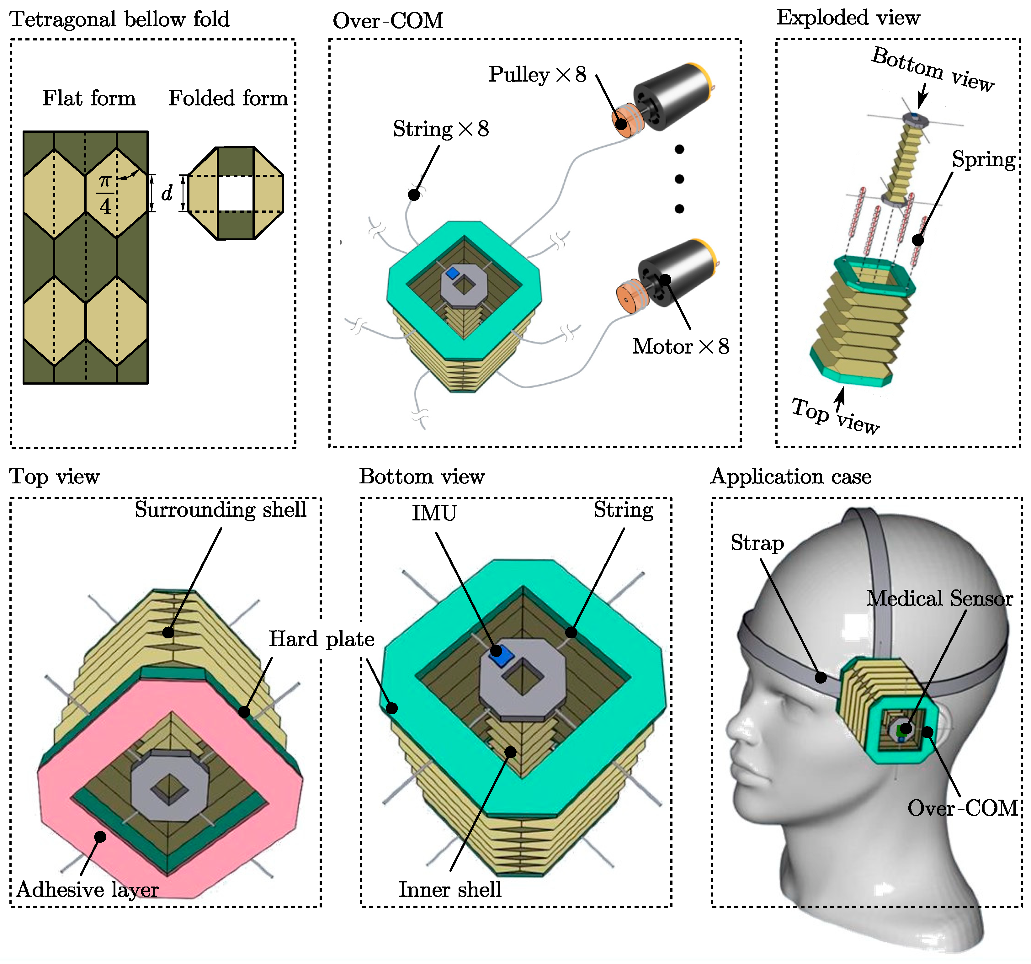
The housing of the Over-COM is targeted at achieving Aim 1 (collapsibility and mountability). As shown in
Figure 1, it consists of a surrounding shell (rigid top and bottom plates are in turquoise) and a central inner shell (rigid top and bottom plates are in grey) used for holding a medical diagnostic sensor (driven by eight strings). The outer and inner shells can collapse in the axial direction through a tetragonal bellow-fold pattern along the side walls. The fold pattern, based on a pattern used by Schenk et al. for inflatable space structures [
15], is illustrated in the tetragonal bellow fold of
Figure 1. The tetragonal bellow fold pattern is as follows: the left diagram shows the pattern in flat form, with the dashed lines representing valley folds, and the solid lines representing mountain folds; the right diagram shows the top view of the folded structure. The two most important features of the tetragonal bellow-fold pattern are the minimal fold length and the available internal space when the structure is folded, which would enforce a straight deployment in the axial direction and allow the central inner shell to be stowed together within the surrounding shell. The housing parameters are shown in the
Table 1.
The side walls of the inner shell and surrounding shell are made of waxed construction paper to retain the crease patterns and provide strong rigidity and a slight level of water resistance to the structure. The exploded view in
Figure 1 shows four springs originally in the side wall of the surrounding shell to increase the stiffness. When extended, the surrounding shell retains the shape with the help of the four springs at each corner, as demonstrated in the exploded view in
Figure 1. Each spring, having an original uncompressed length of 15 cm (>10 cm) and a compression limit of 2 cm, has an internal string of length 10 cm within it to restrict its extension. The four springs are situated at the four corners to ensure even extension at every corner. The springs can compress to 2 cm when the housing is compressed and only extend up to 10 cm when the housing is extended. The springs provide an outward force on both ends to maintain the structural rigidity of the bellow-fold side walls by a restricted length (10 cm internal strings). This approach was adapted from the actuator model developed by Banerjee et al. [
11]. The side walls of the surrounding shell are attached at the top and bottom to rigid plates through which strings pass to control the inner probe holder. The inner shell is an extendable bellow-fold side wall sandwiched by two rigid plates. These rigid plates are the control points attached to the motors by nylon strings.
When used, the extension of the inner shell relies on the extended surrounding shell via the strings and the internal friction between the cavity walls and the medical sensor. The strings then allow the inner shell to be moved relative to the surrounding shell. The inner shell also features an IMU, which can relay information to the off-board controller. Thus, the medical sensor can be held by the inner shell and moved by the actuation of the strings to locate the ROIs and adjust posture and penetration angle.
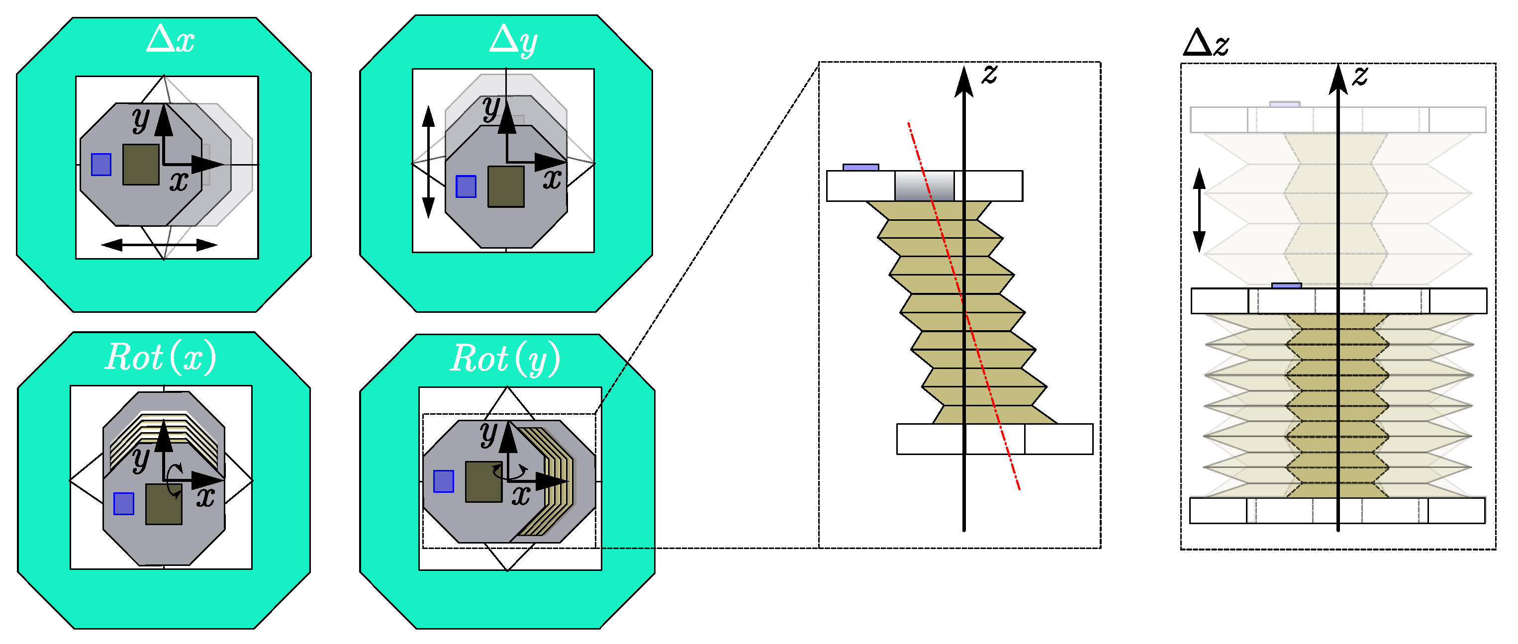
The actuators implemented in the Over-COM are targeted at achieving Aim 2 (movement). The Over-COM has 4 + 1 DOFs achieved by the eight motor-actuated strings attached to the inner shell and pass-through holes in the (top and bottom) rigid plates of the surrounding shell, as shown in
Figure 1. The collapsing of the surrounding shell takes 1 DOF along the vertical axis perpendicular to the skin plane (taken to be the
z-axis), as shown in the right diagram of
Figure 2. The other 4 DOFs lie in the inner shell movement, in the form of translational motion along the
x and
y-axes parallel to the skin plane and rotation about those axes, as presented in the left four diagrams of
Figure 2.
On the external unit end, the eight strings are wound around their pulleys (diameter
cm) mounted to the shafts of the eight respective rotary motors (RS no: 752-2005,
= 60 rpm). Thus, the maximum translation velocity of the inner shell can be calculated by Equation (1). Between the housing and the external unit, each string runs inside a sheath, and the sheaths are collectively channeled through a single cable for ease of management. The justification for this over-actuated system is that a closed string loop controlled by a single rotary motor cannot release extra string lengths while maintaining tension to facilitate inner shell movement, i.e., the inner shell would only be able to translate diagonally.
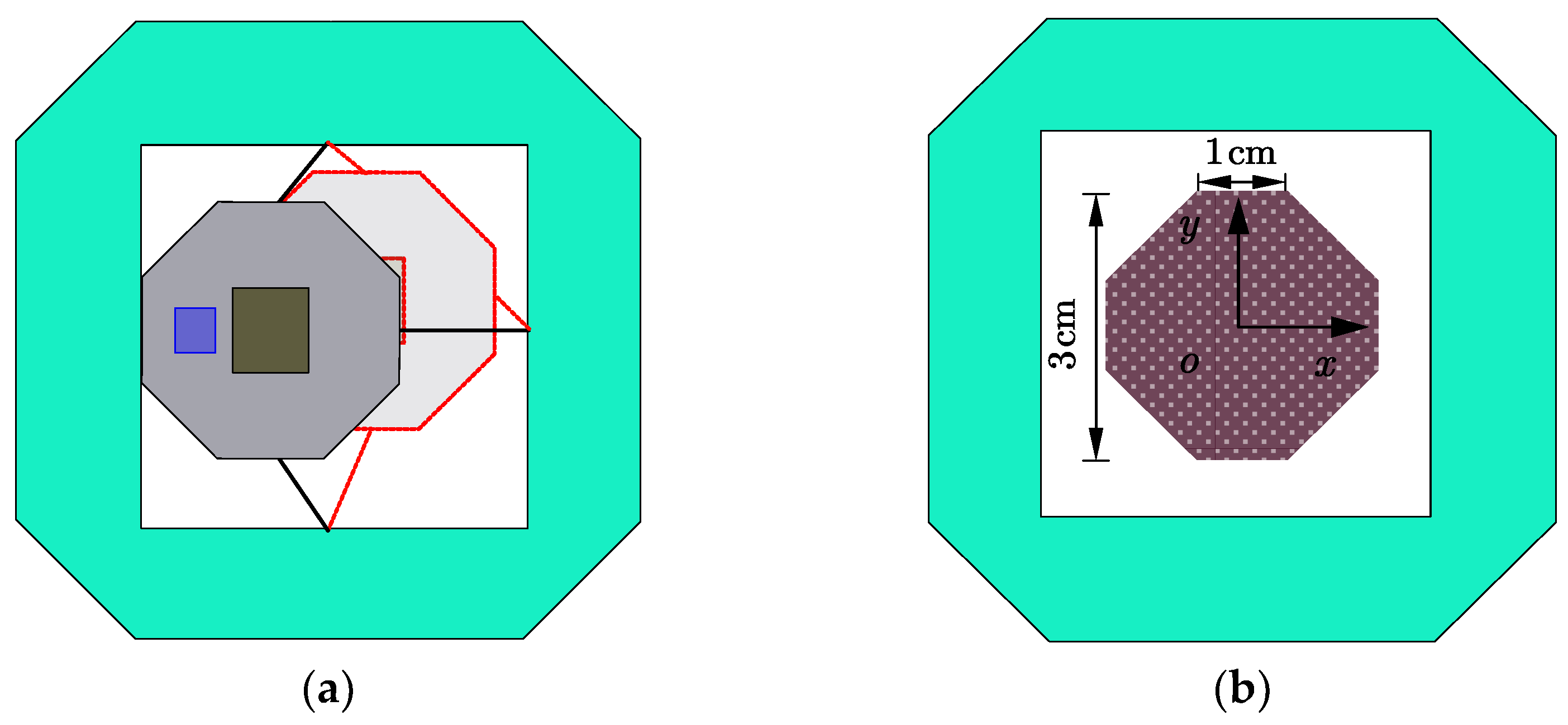
The scanning area achieved by the movement of the inner shell is presented in
Figure 3. The extreme positions that the inner shell can reach are shown in
Figure 3a. The solid diagram shows the extreme side position, while the red dashed diagram illustrates the extreme corner position, resulting from the fact that the strings can only carry pull force. Relevant dimensions of the scanning area are labeled. Note that the brown octagon in
Figure 3b is not a regular octagon with 1 cm sides. It has 1 cm horizontal/vertical sides and
cm diagonal sides. The scan area is 7
.
As presented in the middle diagram of
Figure 2, the theoretical maximum rotation angle
of the inner shell along the
x or
y-axes can be determined by the formula
, where
is the height of the inner shell. Thus, the maximum angle is
.
3.2. Control System Design
The sensing portion of the Over-COM is targeted at achieving Aim 3 (Positional). An IMU (model number ICM-20789 [
14]) is mounted at the top of the inner shell to determine the spatial position in relation to the surrounding shell, as shown in blue in
Figure 1. Then, the controller will receive and analyze the spatial data to determine the best path to scan the optimal medical signal and stabilize the inner shell.
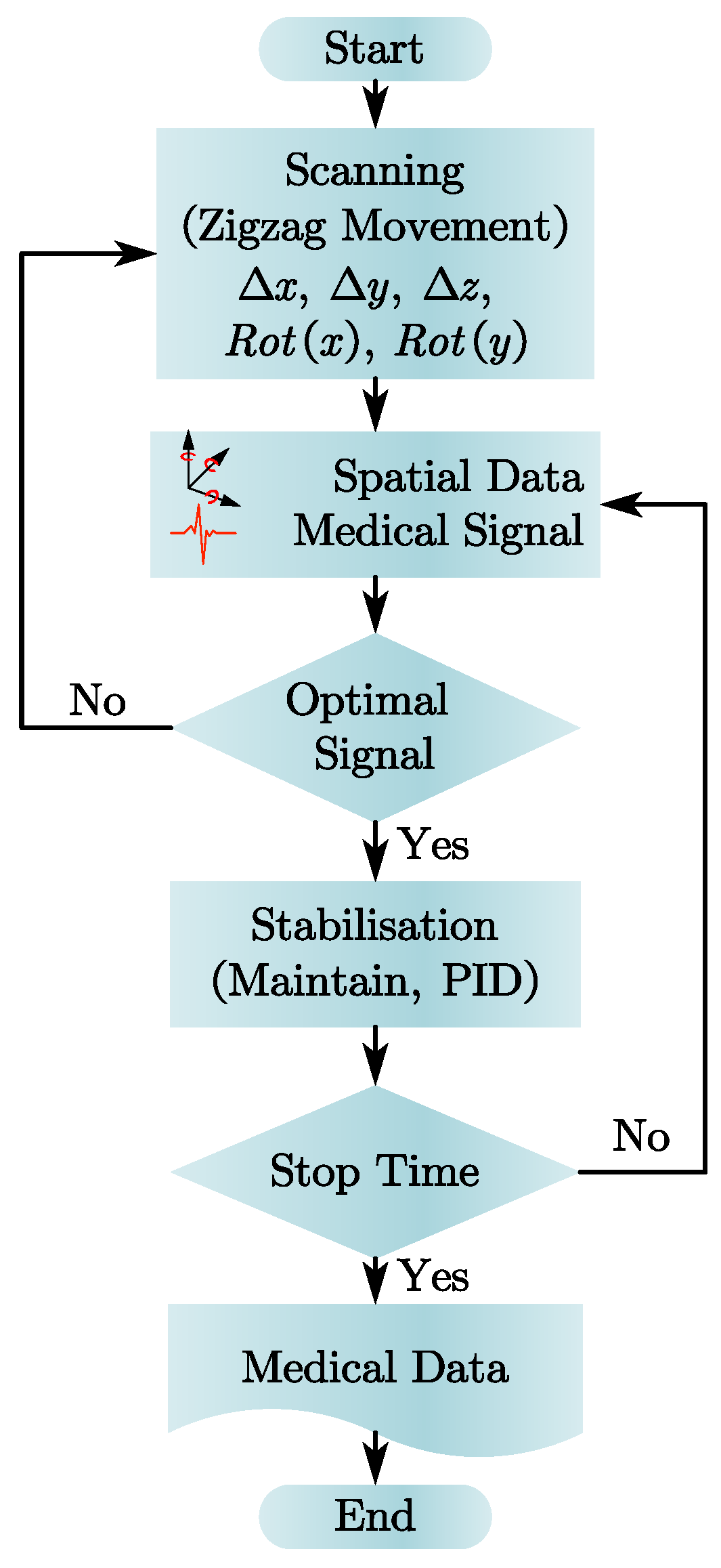
The controller implemented in the Over-COM aims to achieve Aim 4 (Control System). A microcontroller Arduino MKR GSM 1400 (Arduino, Monza, Italy) [
16] stores our proposed device’s main scanning and stabilization protocols. The controller takes the medical data from the diagnostics devices and the spatial data from the IMU as input, and if there is a stable and robust signal whose magnitude lies above a pre-set threshold (indicative of an optimal signal), the stabilization protocol is executed; if the optimal signal is absent, the scanning protocol will continue.
Figure 4 shows the computational flow chart from the start of the device. Before the stabilization protocol, the scanning protocol is executed, and the spatial data at the end of the scanning protocol is used as the stability locus to maintain. The planned movement of the inner shell occurs in two phases: translational and rotational. During the translational phase, the inner shell is moved laterally across the skin plane in a zig-zag manner (from scan boundary to scan boundary) until the medical signal is found. The inner shell then stops translating in the skin plane. Subsequently, during the rotational phase, the inner shell is rotated about the
x and
y-axes simultaneously to produce a precise motion about the vertical axis at the located position. The purpose is to find the best posture and penetration angle to optimize the signal magnitude found previously in the translational phase.
Once the optimum periodic signal is found, the spatial position of the inner shell is noted as the stability locus, and the stabilization protocol is executed. The stabilization protocol involves a PID controller that takes the inner shell’s spatial data as feedback. In the presence of vibrations, the change in spatial data received would trigger the PID controller to enact the countering movement to maintain the stability locus. However, if the inner shell fails to stabilize due to unforeseen external factors, the scanning protocol will be executed again to find the periodic medical signal.
3.3. Prototype Implementation
A prototype of the Over-COM was fabricated to test the movement mechanism of the inner shell, as presented in
Figure 5, which shows the expanded and collapsed versions of the setup. The prototype was used to verify the four individual DOFs: translation and rotation, each along 2 axes. The viability of the movement in the translational rotational phases for the scanning protocol was also tested.
The variables
T1–
T4 in
Figure 5 stand for the tensions of the four strings on the top of the Over-COM, while
T5–
T8 represent the tensions of the four strings on the bottom. The directions of the tensions are in the
o-
xy plane, along positive or negative
x or
y directions. Thus, the top and bottom resultant forces,
and
, can be written as follows in Equation (2):
If the , the inner shell will achieve translation motion, while if the , rotational motion of the inner shell is triggered.
4. Experiment
In this section, we discuss the validation of the prototype Over-COM’s performance. Experiments testing the Over-COM’s four DOFs were conducted to lay a foundation for further research. The DOF of the expansion in the
z-axis is excluded, as it has already been presented in
Figure 6. Then, the predetermined scan protocol experiment was carried out.
4.1. Verification of Four DOFs
Experiments were conducted to verify the performance of the Over-COM’s four DOFs, including translational movement along the x and y-axes and rotational movement around those axes.
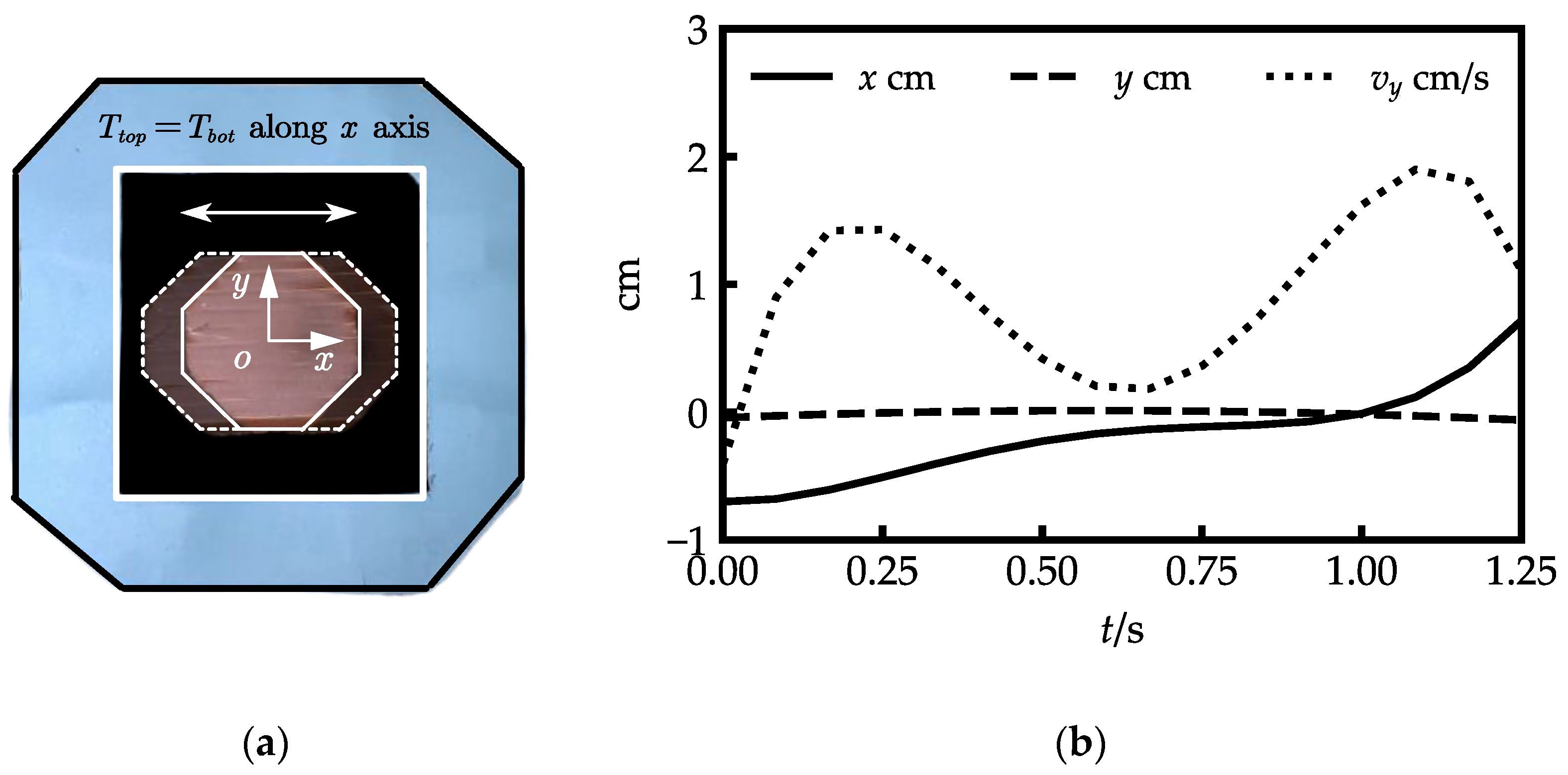
Figure 6 illustrates the translational movements along the
x-axis. The movement can achieved by setting
, which should also be oriented along the
x-axis. The shallow inner-shell top plate with dashed lines in
Figure 6a represents the movement of the inner shell along the
x-axis, and the dark top plate with solid lines shows the inner shell’s neutral position. The origin of the coordinate
o-
xy is located at the center of the top plate.
Figure 6b illustrates the translation curves of the coordinate origin. The inner shell moved from (−0.702 cm, −0.038 cm) to (0.711 cm, −0.048 cm) with a mean error of −0.012 cm along the
y-axis.
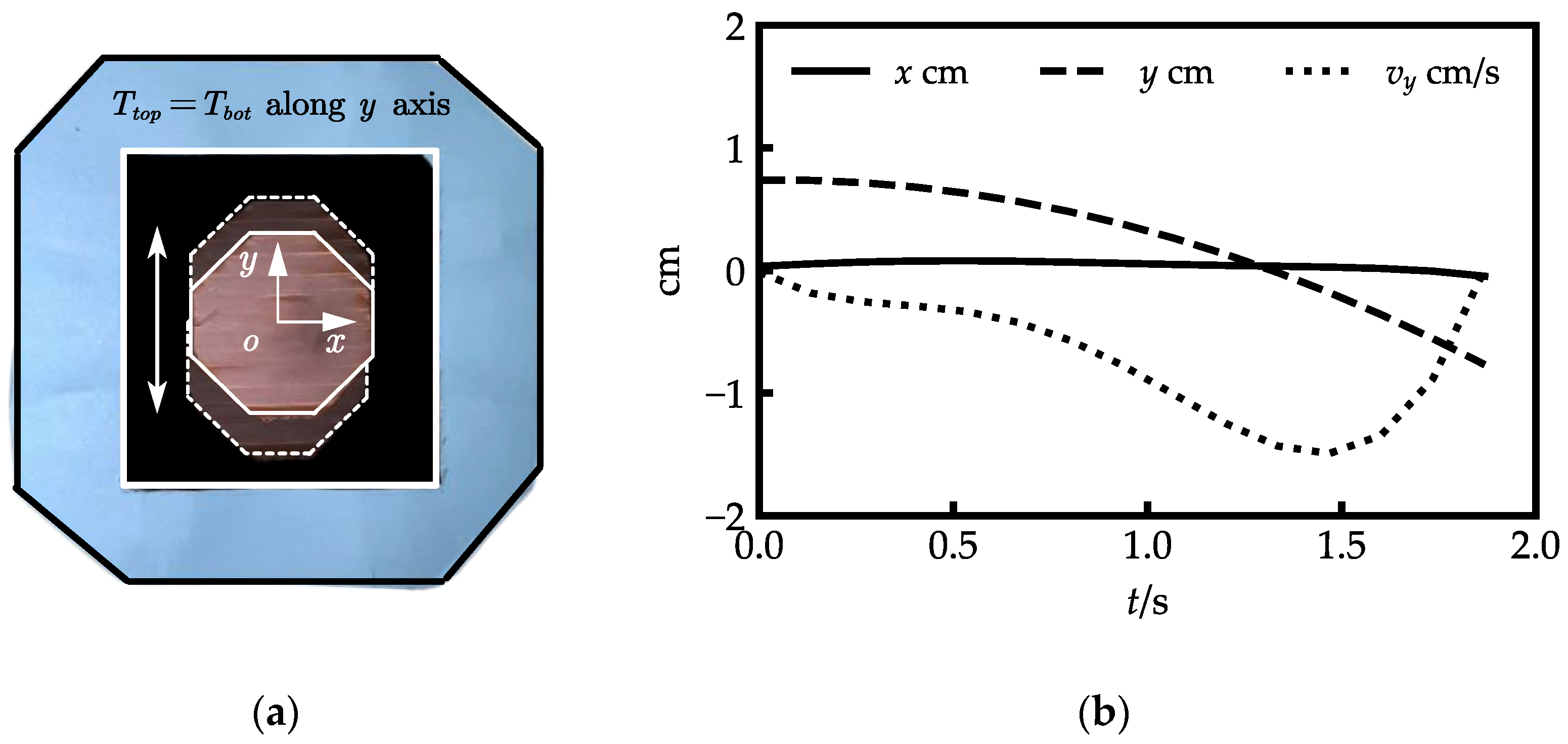
Figure 7 illustrates the translational movements along the
y-axis. The movement can be achieved by setting
, which should also be oriented along the
y-axis. The shallow inner-shell top plate with dashed lines in
Figure 7a represents the movement of the inner shell along the
y-axis.
Figure 7b illustrates the translation curves of the coordinate origin. The inner shell moved from (0.095 cm, 0.752 cm) to (−0.040 cm, −0.686 cm) with a mean error of −0.042 cm along the
x-axis.
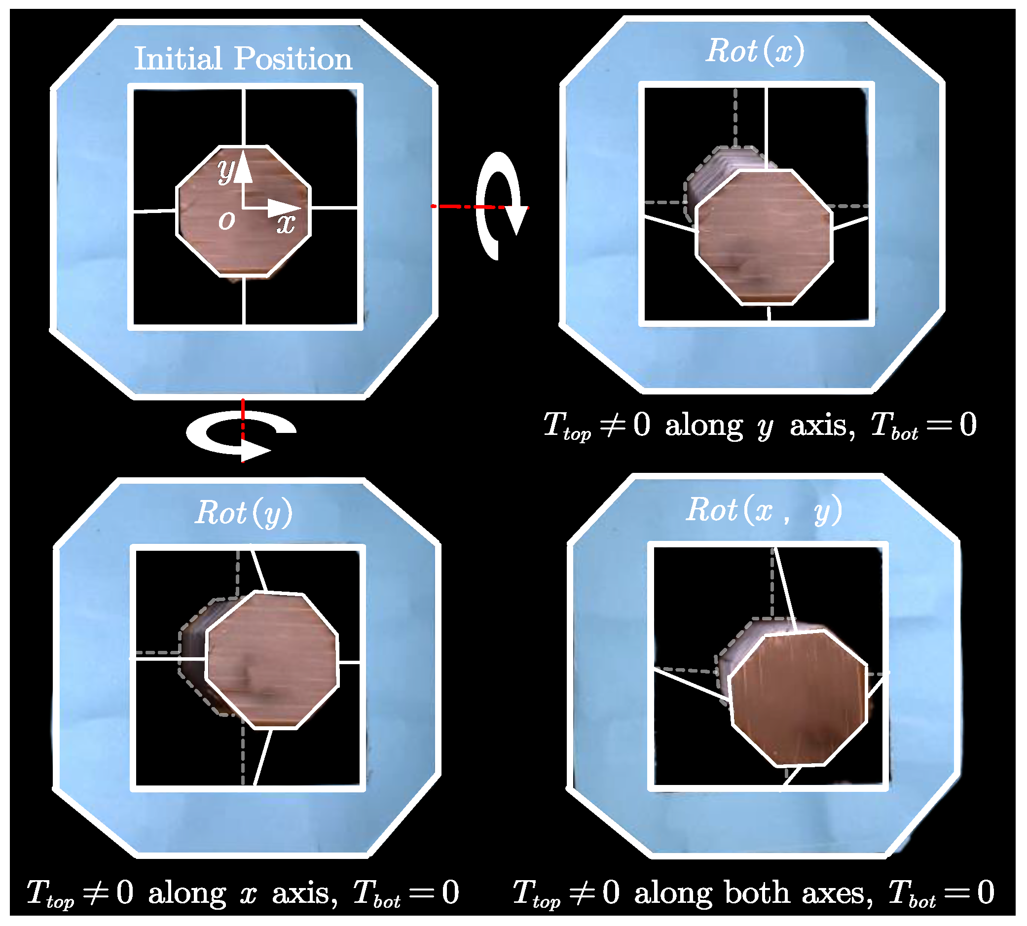
The two-DOF rotations of the inner shell along the
x and
y-axes are presented in
Figure 8: the top plate of the inner shell is in solid white lines, and the bottom plate of the inner shell is in dashed light white lines. The rotation around the
x-axis is shown in the top-right diagram of
Figure 8. During that process, the orientation of the
was along the negative
y-axis, which pulled the top plate downwards, and the bottom plate was maintained at the neutral position by
.
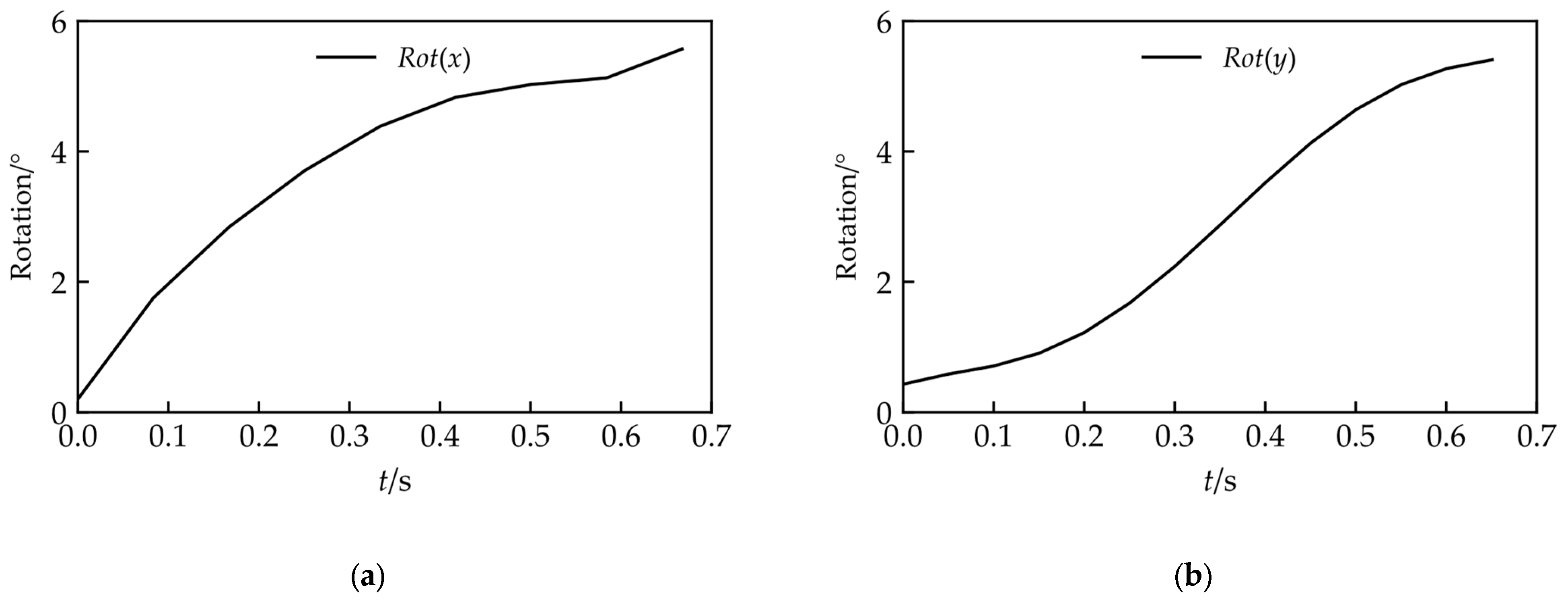
Figure 9a shows the rotation angle on the
x-axis along with the time change; the rotation angle varies from
to
.
The rotation around the
y-axis is shown in the bottom-left diagram of
Figure 8. In that process, the orientation of the
was along the positive
x-axis, which pulled the top plate towards the right, and the bottom plate was maintained at the neutral position by
.
Figure 9b shows the rotation angle on the
y-axis along with the time change; the rotation angle varies from
to
.
The bottom-right diagram of
Figure 8 shows the combined rotation of the inner shell along the
x and
y-axes.
4.2. Scanning Protocol
As shown in
Figure 10, the scanning protocol consists of two phases: the Translational phase and the Rotational phase. Under the first phase (
Figure 10a), a zig-zag movement of the inner shell is executed by the actuation of strings to locate the position of the medical signal. The inner shell first translates along the
y-axis, then goes a small step along the
x-axis. After that, the inner shell moves in the
y-axis again to scan the second line. This procedure will repeat until the targeted signal is located. The inner shell then moves on to the rotational phase (
Figure 10b), where its bottom plate position is fixed (
), and its top plate shifts along the
x and
y-axes to adjust the posture and penetration angle of the medical sensor until the optimal targeted signal is detected.
Due to an equipment shortage, the scanning protocol experiment was carried out without the medical diagnostics apparatus, and the path of the inner shell was predetermined.
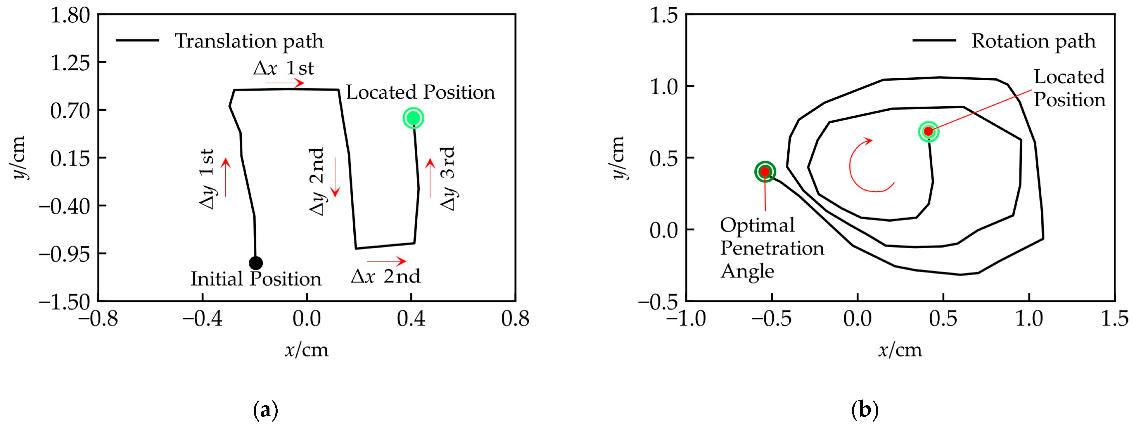
Figure 11 and
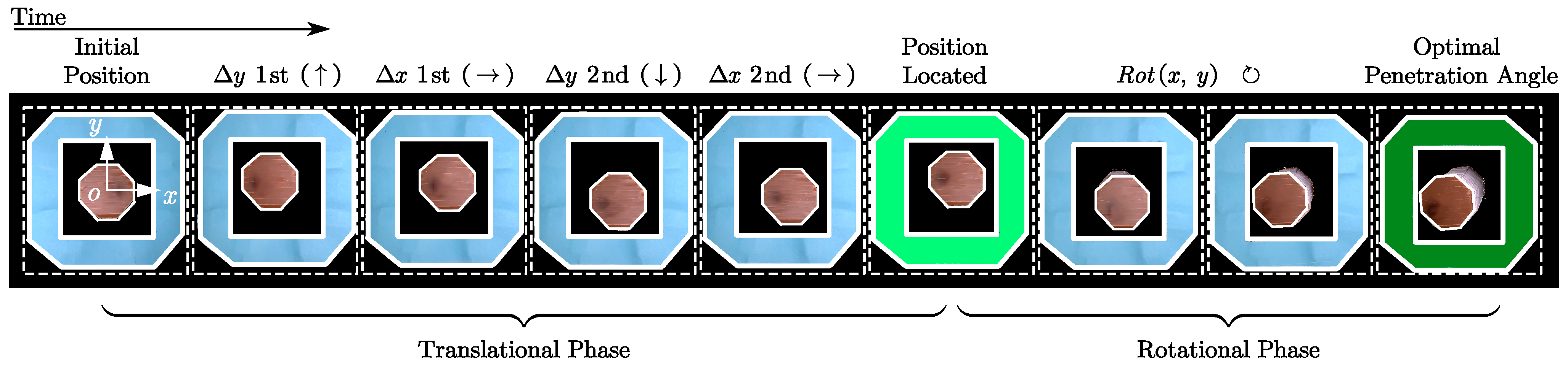
Figure 12 illustrate the experimental results. The pictures, in time sequence from left to right, are shown in
Figure 11. The coordinates are established by reference to the center of the neutral position of the inner-shell top plate. In the Translational Phase (
Figure 12a), the inner shell first translated from (0.198 cm, −0.998 cm) to (−0.278 cm, 0.928 cm), which is essentially along the
y-axis; then, the inner shell moved to (0.121 cm, 0.931 cm) along the
x-axis; after that, the inner shell scanned the second line along the
y-axis to (0.188 cm, −0.896 cm); subsequently, the inner shell shifted to (0.409 cm, −0.848 cm) along the
x-axis to prepare for the subsequent scanning; eventually, the position was located at (0.408 cm, 0.629 cm) after the third scan along the
y-axis, which is shown in bright green in
Figure 12 and
Figure 13a.
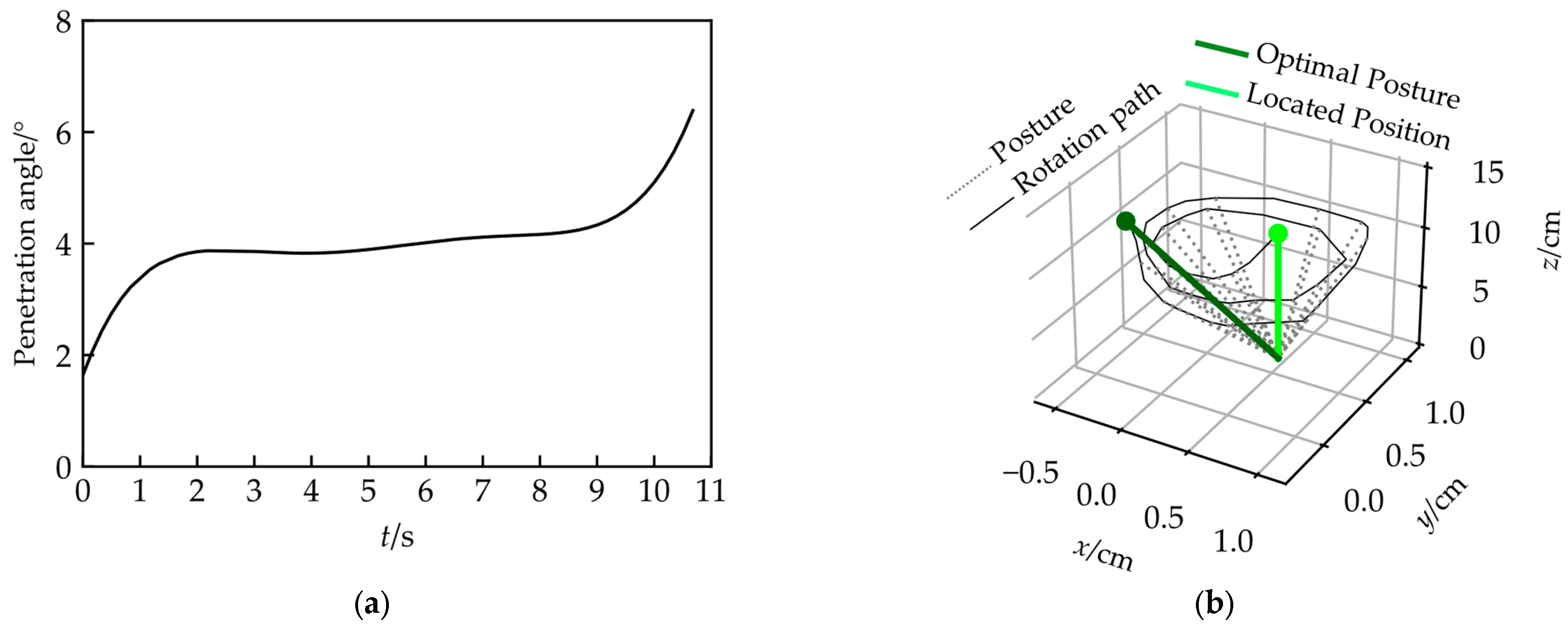
Next, the Over-COM entered the Rotational Phase, and the rotational operation of the inner shell was carried out along the
x and
y-axes to alter the medical sensor’s posture and penetration angle. The rotation path of the top plate’s center is a spiral (
Figure 12b), along with an increment of the penetration angle from (1.64
to 6.39
, shown in
Figure 13a). Thus, a series of medical sensor posture adjustments was achieved, shown in
Figure 13b. In
Figure 13b, the medical sensor is simplified as a line to describe its posture clearly. The solid bright green line is the initial posture acquired in the Translation Phase, the dashed grey lines are the medical sensor postures during the operation, and the solid dark green line is the final optimal posture with an appropriate penetration angle.
5. Discussion
We proposed an Overhead Origami-based Collapsible Mount (Over-COM) for Medical Applications. The Over-COM provides a method of holding the medical sensor steady to carry out head-related diagnoses, offers feasible scanning for the ROIs, and adjusts the posture and penetration angle of the medical scanner. It would allow a non-trained clinician to operate the medical sensor, recording the relevant medical information in an instant scenario, so that the data can be reported to the medical staff at the hospital to make a rapid diagnosis. The Over-COM offers the possibility of conducting a quick medical inspection of a patient’s head in the ambulance, getting an immediate diagnosis, and creating the best chance to save the patient’s life.
The Over-COM’s beneficial features of being collapsible, mountable, portable, lightweight, high-compliance, and small-size are acquired by the origami-based design. The height of the entire housing could be collapsed from 10 cm to 2 cm, a significant volume change (80%), making the Over-COM portable while also providing sufficient contact force between the medical sensor and the patient’s skin. In our tests, the Over-COM could hold and move the medical sensor to attain a scanning velocity of up to 3.14 cm/s and a scan area of up to 7 cm2, which is adequate to locate the ROIs. Additionally, the penetration angle reached an adjustment 0~45° to track the optimal medical signal in the patient’s head.
The four-DOFs experiments proved that the inner shell of the Over-COM could both translate and rotate along the x and y-axes, which is in line with our expectations. The two-DOFs translation experiments along the x and y-axes showed that movement along one axis resulted in only a small amount of movement along the other. Those errors were caused by the deformation of the surrounding shell and inner shell. However, we believe those deviations are minor in relation to the medical signal scan. The two-DOFs rotation experiments along the x and y-axes demonstrated the controllability of the medical sensor’s posture and penetration angle by the Over-COM.
In the Translation Phase of the scanning protocol experiment, the Over-COM held and moved the medical sensor to shift the sweep signal to follow a predetermined pattern. After locating the ROIs, the Over-COM entered the Rotation Phase, which took advantage of its elasticity from the origami design to adjust the medical sensor to determine the best posture and penetration angle. The results demonstrated that the Over-COM could be guided by the medical diagnostic equipment or a predetermined strategy to locate the optimal medical signal.
Currently, the housing of the Over-COM is extended and rigidized through springs and strings at each corner of the surrounding shell (refer to
Figure 1), which is not entirely controlled. The rigidization process could be replaced with an electrically conductive shape memory polymer (SMP), insulated on the surface to construct the tetragonal bellow-fold side walls. The rigidization procedure can be thermally controlled by Joule heating from a current. SMPs have many advantages, including low cost and density, easy and fast shape training, and high biocompatibility and biodegradability [
17,
18].
In future research, the medical diagnosis apparatus should be involved and should communicate with the Over-COM. This preliminary study of Over-COM does not consider the influence of the medical sensor intended to be installed in the inner shell. The mass and inertia of the sensor will have an enormous impact on the system. Further study of the controller should consider the system dynamic, and the influence of the medical sensor should be evaluated to improve the system’s robustness and stability. AI technology could also be introduced to identify the ROIs, plan the scan path, and decide the medical sensor’s best posture and penetration angle. It could also help untrained operators conduct a quick diagnosis according to the collected signals, which could further remove the burden of training from the operator. Thus, operators could easily interpret the medical signals from the Over-COM, even without complex operative skills, medical knowledge, or a great wealth of experience.
6. Conclusions
The Over-COM proposed in this study provides an easy-to-use, mountable, portable, collapsible, lightweight, low-cost solution for non-trained operators to carry out rapid diagnosis of patient’s head injuries. The prototype of the Over-COM has proven the validity of the medical holder’s movements and the viability of the design in its application. The two-DOF translation and two-DOF rotation experiments demonstrated the high performance of the Over-COM in scanning for medical signals, as well as adjusting the medical sensor’s posture and penetration angle. The two-phase scanning protocol experiment verified the effectiveness of the Over-COM to locate the ROIs and detect the optimal signal.
In future studies, improvements to the Over-COM will be implemented for better functionality, including the SMP-based housing design and AI algorithms. The Over-COM will be optimized to be deployed in ambulance settings. Thus, an invaluable identification of the physiological indicators in patients could be achieved ahead of time for minimal tissue damage, thereby improving the quality of life after treatment.
Author Contributions
H.R., F.L.J.L., I.L., T.S. and L.L.: conceptualization, methodology; F.L.J.L., I.L., T.S. and H.R.: validation, formal analysis; L.L. and H.R.: writing—original draft preparation; L.L., H.R., F.L.J.L., I.L. and T.S.: review and editing. All authors have read and agreed to the published version of the manuscript.
Funding
This research was funded by the Key Project 2021B1515120035 of the Regional Joint Fund Project of the Basic and Applied Research Fund of Guangdong Province, Singapore Academic Research Fund under Grant R397000353114, Health Longevity Catalyst Awards HLCA/E-403/22 by NAM & RGC, Shenzhen-Hong Kong-Macau Technology Research Programme (Type C) Grant 202108233000303, Hong Kong Research Grants Council (RGC) Collaborative Research Fund (CRF C4026-21GF) 2300075 and (GRS)#3110167.
Institutional Review Board Statement
Not applicable.
Informed Consent Statement
Not applicable.
Data Availability Statement
Not applicable.
Conflicts of Interest
The authors declare no conflict of interest.
References
- Smiljkovic, M.; Renaud, C.; Tapiero, B.; Lamarre, V.; Kakkar, F. Head ultrasound, CT or MRI? The choice of neuroimaging in the assessment of infants with congenital cytomegalovirus infection. BMC Pediatr. 2019, 19, 1–6. [Google Scholar] [CrossRef] [PubMed]
- Wiggins, R.H.; Hoffman, J.M.; Fine, G.C.; Covington, M.F.; Salem, A.E.; Koppula, B.R.; Morton, K.A. PET-CT in clinical adult oncology—V. head and neck and neuro oncology. Cancers 2022, 14, 2726. [Google Scholar] [CrossRef] [PubMed]
- Wu, K.C.; Sunwoo, J.; Sheriff, F.; Farzam, P.; Farzam, P.Y.; Orihuela-Espina, F.; LaRose, S.L.; Monk, A.D.; Aziz-Sultan, M.A.; Patel, N. Validation of diffuse correlation spectroscopy measures of critical closing pressure against transcranial Doppler ultrasound in stroke patients. J. Biomed. Opt. 2021, 26, 036008. [Google Scholar] [CrossRef] [PubMed]
- Zhang, D.; Yao, L.; Chen, K.; Wang, S.; Chang, X.; Liu, Y. Making sense of spatio-temporal preserving representations for EEG-based human intention recognition. IEEE Trans. Cybern. 2019, 50, 3033–3044. [Google Scholar] [CrossRef] [PubMed]
- Hu, H.; Zhu, X.; Wang, C.; Zhang, L.; Li, X.; Lee, S.; Huang, Z.; Chen, R.; Chen, Z.; Wang, C. Stretchable ultrasonic transducer arrays for three-dimensional imaging on complex surfaces. Sci. Adv. 2018, 4, eaar3979. [Google Scholar] [CrossRef] [PubMed]
- Iyer, P.C.; Madhavan, S. Non-invasive brain stimulation in the modulation of cerebral blood flow after stroke: A systematic review of Transcranial Doppler studies. Clin. Neurophysiol. 2018, 129, 2544–2551. [Google Scholar] [CrossRef] [PubMed]
- Sarkar, S.; Ghosh, S.; Ghosh, S.K.; Collier, A. Role of transcranial Doppler ultrasonography in stroke. Postgrad. Med. J. 2007, 83, 683–689. [Google Scholar] [CrossRef] [PubMed]
- Tsuda, T.; Geary, E.M.; Temple, J. Significance of automated external defibrillator in identifying lethal ventricular arrhythmias. Eur. J. Pediatr. 2019, 178, 1333–1342. [Google Scholar] [CrossRef] [PubMed]
- Gomez, C.R.; McLaughlin, J.R. Transcranial Doppler Transducer Housing Stabilizer. U.S. Patent 5070 880A, 10 December 1991. [Google Scholar]
- Giller, C.A.; Giller, A.M. A new method for fixation of probes for transcranial Doppler ultrasound. J. Neuroimaging 1997, 7, 103–105. [Google Scholar] [CrossRef] [PubMed]
- Esmaeeli, S.; Hrdlicka, C.M.; Bastos, A.B.; Wang, J.; Gomez-Paz, S.; Hanafy, K.A.; Lioutas, V.-A.; Ogilvy, C.S.; Thomas, A.J.; Shaefi, S. Robotically assisted transcranial Doppler with artificial intelligence for assessment of cerebral vasospasm after subarachnoid hemorrhage. J. Neurocritical Care 2020, 13, 32–40. [Google Scholar] [CrossRef]
- Qiu, Q.; Yang, X.; Liu, J.; Zhang, P.; Wu, X. A robotic holder of transcranial doppler probe for CBFV auto-searching. In Proceedings of the 2013 IEEE International Conference on Information and Automation (ICIA), Yinchuan, China, 26–28 August 2013; pp. 1284–1289. [Google Scholar]
- Mackinnon, A.D.; Aaslid, R.; Markus, H.S. Long-term ambulatory monitoring for cerebral emboli using transcranial Doppler ultrasound. Stroke 2004, 35, 73–78. [Google Scholar] [CrossRef] [PubMed]
- Bishop, C.; Powell, S.; Rutt, D.; Browse, N. Transcranial Doppler measurement of middle cerebral artery blood flow velocity: A validation study. Stroke 1986, 17, 913–915. [Google Scholar] [CrossRef] [PubMed]
- Schenk, M.; Viquerat, A.D.; Seffen, K.A.; Guest, S.D. Review of inflatable booms for deployable space structures: Packing and rigidization. J. Spacecr. Rocket. 2014, 51, 762–778. [Google Scholar] [CrossRef]
- ArduinoOfficial. Arduino MKR GSM 1400. Available online: https://store.arduino.cc/products/arduino-mkr-gsm-1400 (accessed on 28 December 2022).
- Liu, C.; Qin, H.; Mather, P. Review of progress in shape-memory polymers. J. Mater. Chem. 2007, 17, 1543–1558. [Google Scholar] [CrossRef]
- Jani, J.M.; Leary, M.; Subic, A.; Gibson, M.A. A review of shape memory alloy research, applications and opportunities. Mater. Des. 1980–2015 2014, 56, 1078–1113. [Google Scholar]
Figure 1.
Tetragonal bellow-fold pattern;, overview; exploded, top, and bottom views of computer-aided design (CAD) of the Over-COM; and an application case which shows the setup mounted onto the temporal window of the patient’s head with the bottom adhesive and accompanying head straps.
Figure 1.
Tetragonal bellow-fold pattern;, overview; exploded, top, and bottom views of computer-aided design (CAD) of the Over-COM; and an application case which shows the setup mounted onto the temporal window of the patient’s head with the bottom adhesive and accompanying head straps.
Figure 2.
The 5 DOFs of the Over-COM. The four schematics on the left show the top view of the inner shell’s 4 DOFs in translational and rotational motion. The middle schematic shows the side view of the inner shell in . The right schematic shows the vertical collapsing DOF of the Over-COM along the z-axis.
Figure 3.
Scanning area covered by the inner shell: (a) extreme positions; (b) scan area.
Figure 3.
Scanning area covered by the inner shell: (a) extreme positions; (b) scan area.
Figure 4.
Computational flow chart of the Over-COM.
Figure 4.
Computational flow chart of the Over-COM.
Figure 5.
A low-fidelity prototype was constructed to test the Over-COM. On the left, the housings are in the extended form; on the right, the housings are in the collapsed form.
Figure 5.
A low-fidelity prototype was constructed to test the Over-COM. On the left, the housings are in the extended form; on the right, the housings are in the collapsed form.
Figure 6.
Translation of the inner shell along the x-axis: (a) movement images of the inner shell along the x-axis; (b) the center coordinate curves of the inner-shell top plate and the velocity along the x-axis ().
Figure 6.
Translation of the inner shell along the x-axis: (a) movement images of the inner shell along the x-axis; (b) the center coordinate curves of the inner-shell top plate and the velocity along the x-axis ().
Figure 7.
Translation of the inner shell along the y-axis: (a) images of the extreme positions along the y-axis (shallow inner shell in dashed lines); (b) the center coordinate curves (x and y) of the inner-shell top plate, and the velocity along y-axis ().
Figure 7.
Translation of the inner shell along the y-axis: (a) images of the extreme positions along the y-axis (shallow inner shell in dashed lines); (b) the center coordinate curves (x and y) of the inner-shell top plate, and the velocity along y-axis ().
Figure 8.
Rotation movements of the inner shell; 2-DOF rotations around the x and y-axes.
Figure 8.
Rotation movements of the inner shell; 2-DOF rotations around the x and y-axes.
Figure 9.
Rotation curve of the inner shell: (a) rotation angle around the x-axis; (b) rotation angle around the y-axis.
Figure 9.
Rotation curve of the inner shell: (a) rotation angle around the x-axis; (b) rotation angle around the y-axis.
Figure 10.
Schematic diagram of scanning protocol: (a) translational phase; (b) rotational phase.
Figure 10.
Schematic diagram of scanning protocol: (a) translational phase; (b) rotational phase.
Figure 11.
The experiment result of the scan protocol (organized in chronological order from left to right).
Figure 11.
The experiment result of the scan protocol (organized in chronological order from left to right).
Figure 12.
Scanning protocol experimental results: (a) translation path of the first phase; (b) rotation path of the second phase.
Figure 12.
Scanning protocol experimental results: (a) translation path of the first phase; (b) rotation path of the second phase.
Figure 13.
The adjustments of the medical sensor: (a) change in the penetration angle of the inner shell during the rotational phase; (b) posture adjustment of the medical sensor.
Figure 13.
The adjustments of the medical sensor: (a) change in the penetration angle of the inner shell during the rotational phase; (b) posture adjustment of the medical sensor.
Table 1.
Housing parameters of the Over-COM.
Table 1.
Housing parameters of the Over-COM.
| Components | Features | Unit | Values |
|---|
| Strings | Length inside housing | cm | 10 |
| Length outside housing | cm | 200 |
| Compressed Springs | Length | cm | 2~15 |
| Surrounding Shell | External volume | | 8 × 8 × (Expanded from 2 to 10) |
| Cavity volume | | 5 × 5 × (Expanded from 2 to 10) |
| Inner Shell | External volume | | 3 × 3 × (Expanded from 2 to 10) |
| Cavity volume | | 1 × 1 × (Expanded from 2 to 10) |
| Disclaimer/Publisher’s Note: The statements, opinions and data contained in all publications are solely those of the individual author(s) and contributor(s) and not of MDPI and/or the editor(s). MDPI and/or the editor(s) disclaim responsibility for any injury to people or property resulting from any ideas, methods, instructions or products referred to in the content. |
© 2023 by the authors. Licensee MDPI, Basel, Switzerland. This article is an open access article distributed under the terms and conditions of the Creative Commons Attribution (CC BY) license (https://creativecommons.org/licenses/by/4.0/).


