1. Introduction
Repetitive movements are well known to have a positive impact in improving muscle strength and movement coordination in patients with disorders due to neurological or orthopedic problems [
1]. Robot-Aided Training is an alternative for manually assisted training. This latter has several known limitations. Manual training requires intensive effort from the trainer, which limits the time and efficiency of the training session. Fatigue of the therapist, lack of repeatability and lack of objective measures often make the manual training inefficient and any progress of the patient relatively difficult to evaluate. In contrast, robot-assisted training can deliver consistent and repeatable exercises for the patient. Therefore, the efficiency of the training is improved and more quantitative measures can help in measuring the progress of the therapy. A study presented by Veerbeek et al. [
1] showed that a robotic assisted therapy can increase the number of repetitions which allows a higher intensity of practice, while being safe. Further, the requests for therapist assistance increased; in fact, the COVID-19 pandemic has transformed daily life and pushed to reduce all possible contact through the proposal of new rehabilitation systems [
2].
Traditional metrics of performance are usually subjective, and the physiotherapist can only estimate the progress of a patient during the different sessions. However, robot-based rehabilitation systems can tremendously improve the measurements of the different parameters, e.g., range of motion, forces, torques, etc.; these systems can hence yield a more objective evaluation of the progress of the patient. On the other hand, from a design point of view, due to their interaction with humans, these robots need a totally different set of requirements than for industrial robots that operate in structured environments. These requirements include safety, compliance, gentleness and ease of use. Several robotic-training systems have been presented in the literature [
3]. Different designs were proposed for rehabilitation, e.g., serial manipulators [
4] (ARM Guide, MIT Manus), cable-driven robots (NeReBot, CADEL [
5]) and an exoskeleton-based commercial system (ArmeoPower).
Several designs have been proposed for rehabilitation in the literature but few systems were for the head–neck joint. The most recent one is a system made of a base fixed on the shoulders and a headband secured on the head [
6,
7]. A parallel robot with rigid links is used, which should be adapted and customized according to the patient’s anatomy. Accordingly, the proposed approach copes with these issues. Indeed, comfort and ease of use are ensured for the proposed solution, which are two important factors that can judge the success of such a new device.
The headband plays the role of the parallel robot’s end-effector, which has three revolute-revolute-spherical (RRS) chains between the base and the headband. The objective of this system is to measure and assist the head motion. Cable-Driven Parallel Robots (CDPRs) substitute rigid links with cables. These robots have several advantages: large reachable workspace, high dynamics, low cost and easy reconfigurability [
7]. Several designs have been proposed in the literature where cable-based robots were used in the rehabilitation of the upper extremity [
5] and the lower limb.
The Head–Neck joint is one of the most complex human joints. The muscles involved in this joint are numerous and each one of them plays a role in moving and stabilizing the Head–Neck joint.
Robots were deployed in the last decade in the medical field in many ways. Using these intelligent machines to assist in the rehabilitation process was among the promising fields to assist treatment of sensorimotor deficits in extremities [
7]. By examining the efforts of researchers to date, these robots can be categorized as: grounded exoskeletons, grounded end-effector machines and wearable exoskeleton robots. All the above-mentioned systems target mainly the upper or lower extremities [
8]. The Head–Neck joint was addressed recently by researchers targeting an automated brace for Head–Neck rehabilitation [
9,
10,
11,
12,
13]. So far, the developed solutions are mainly based on the emerging wearable mechanisms; however, mechanisms, such as cable robots, have not yet been considered for the rehabilitation of this important joint.
Cable robots are receiving more and more attention as they present several advantages over rigid-body robots. Indeed, these cable robots are usually simple, lightweight, and relatively low-cost. Moreover, relative to their size, these robots can have a large workspace and can easily be reconfigurable. A crane-like robot was proposed in [
14], where the authors presented a system which can move a load in 2D, while considering the variation in the drum radius. However, controlling cable robots can be challenging. The authors of [
15] proposed a control scheme to reduce the oscillation of a pendulum-like cable robot. The authors of [
16] proposed a control scheme to extend the static workspace, using the dynamics of the robot during a point-to-point trajectory. The applications of cable robots are therefore numerous, and researchers are seeking ways to overcome the challenges related to this type of robots to expand their fields of application. This paper is another attempt to use cable robots for new applications. Indeed, this study conducts fundamental analyses that could be transferred to a practical application related to the rehabilitation of human joints such as the Head–Neck joint.
Cable robots are known to have interesting characteristics which make them the better suited for several applications [
9]. The low cost, the large working space which allows them to cover the entire range of motion of the Head–Neck joint, and the flexibility of the cables which ensure safety and assurance for users, are the main advantages that motivated their selection for this application. The main contribution of this paper is the deployment of a novel solution based on a cable mechanism for developing a Head–Neck rehabilitation robot which provides the complete natural range of head rotation and allows movement training of the Head–Neck Joint. The proposed device is based on the use of a cable-driven parallel robot, which has the advantage of being relatively simple, lightweight, and compact. The optimal cable robot synthesis was carried out based on two criteria, namely the minimization of cable tensions in order to reduce the energy consumption by decreasing the torque provided by the actuators, and the maximization of the end-effector dexterity. The proposed device will be a valuable tool to relieve the physiotherapist from this task. His role will mainly be to adjust the system to the needs of the patient and to monitor the patient’s progress.
This paper is structured as follows:
Section 2 deals with an anatomic description of the Head–Neck joint and its characterization in terms of range of motion using a motion-capture analysis study.
Section 3 reveals the design of the end-effector and specifies the robot modelling. In
Section 4, the formulation of the optimization problem is presented. The obtained results are shown in
Section 5.
Section 6 details and discusses the experimental validation using a real prototype. The paper ends with a conclusion section.
2. Identification of the Head–Neck Joint Range of Motion
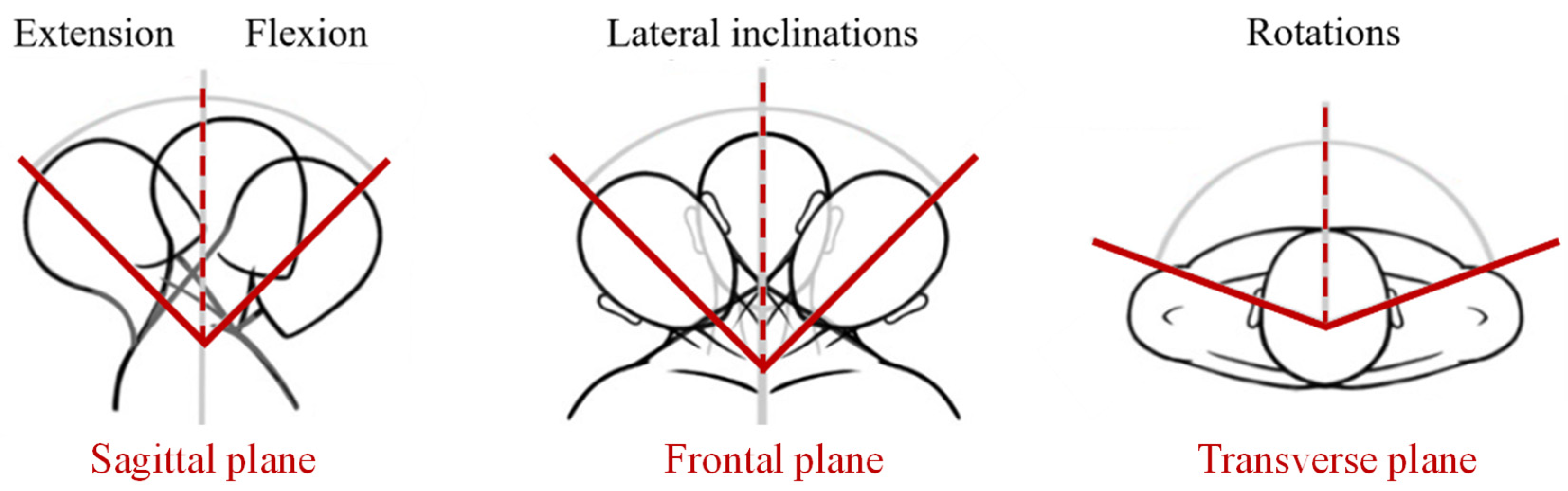
The Head–Neck joint or cervical spine comprises seven of the 24 vertebrae that make up the spine. The cervical vertebrae are numbered from the cranium, beginning with the C1 vertebra, also called the atlas, followed by the axis (C2) to the C7 vertebra. We can distinguish the upper cervical spine, formed by the first two vertebrae, from the lower cervical spine, formed by the last five vertebrae. This complex poly-articulation has two main functions: first, to maintain the head position while allowing a wide range of movement in order to direct the gaze,; and second, to protect the spinal cord and the various spinal nerves. The rotation of the head is mainly made possible by the first two vertebrae of the spine, making the upper cervical spine the main source of mobility. Thus, this poly-articulation allows the rotation of the head in relation to the thorax in three distinct planes represented in
Figure 1 [
17,
18,
19].
The anterior part of the vertebrae consists of a vertebral body whose upper and lower surfaces are almost flat. These faces, called vertebral plates, allow the articulation of a vertebra in relation to its neighbor through the intervertebral discs. These discs are cartilages that ensure mobility between two vertebrae and allow shock absorption. The ligaments limit excessive movements of the joint, hence ensuring its integrity and stability. Finally, the cervical spine is the point of origin and insertion of many muscles whose functions are to stabilize and/or allow mobility of the head–neck joint. We can classify the neck muscles according to their positions (anterior or posterior muscles) and their depth in relation to the spine (superficial, intermediate or deep muscle) [
20].
Multiple pathologies can be encountered in the cervical spine. These pathologies can be classified according to different categories: traumatic (e.g., fracture), degenerative (e.g., osteoarthritis, herniated disc), inflammatory (e.g., disc disease, spondyloarthritis), infectious or tumorous. Depending on their origin, they can threaten the nerves of the upper limbs and the spinal cord and cause cervicalgia, i.e., sharp pain in the neck. Pain associated with the cervical spine and the muscles surrounding it is one of the leading causes of disability. According to the French Chiropractic Association, 67% of the population will suffer from neck pain during their lifetime [
19,
20]. When the pain is too severe, a cervical collar is recommended, with or without the use of anti-inflammatory drugs, to rest the neck. However, the use of a neck brace should be limited as it can lead to amyotrophy in the long term. Physiotherapy, i.e., rehabilitation of the joint with physiotherapy and/or osteopathy sessions, can thus complete the treatment. Postural and proprioceptive rehabilitation, through a program of specific exercises adapted to the pathology of each patient, helps to further relieve the pain and prevent recurrences [
20,
21].
In order to design a CDPR for training of the Head–Neck joint, four head movements were identified. Three rotational movements, i.e., flexion/extension, right and left inclinations, and right and left axial rotations, are shown in
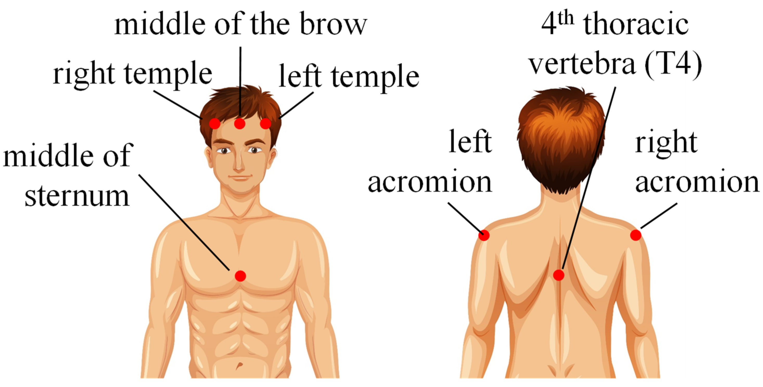
Figure 1. The fourth movement is a circular one, where the head goes through the maximum flexion/extension positions and the maximum lateral inclinations to the right and left. To estimate the range of these movements, experimental measurements were carried out. A motion-capture system was used for these measurements. The ranges of movements were recorded using 8 high-resolution infrared cameras and 7 passive reflective markers fixed on the head and the upper body of the person (
Figure 2).
Four volunteers between 20 and 30 years old participated in the experiments. The volunteer was asked to sit in a chair with his back straight and in permanent contact with the backrest to ensure that the head is always vertical and that the person is looking straight ahead. Before starting the measurements, the volunteer was asked to warm up by executing repetitive movements. This warm-up session ensures better repetitiveness in the measurement, hence improving the accuracy of the results. In fact, these steps allow the subject to be prepared for the various movements that are required of him. In addition, stretching improves the performance in terms of flexibility, and therefore the range of motion, by stretching the muscles of the cervical spine as much as possible. The warming up sessions limit the risk of pain, as the joint will be stretched to its maximum amplitude, which is not usual and can therefore cause some discomfort.
The volunteers were asked to complete 10 cycles for flexion/extension, right/left lateral inclinations and right/left rotations. Then, 5 cycles of a circular combined motion by turning clockwise then counter-clockwise were executed by the volunteer.
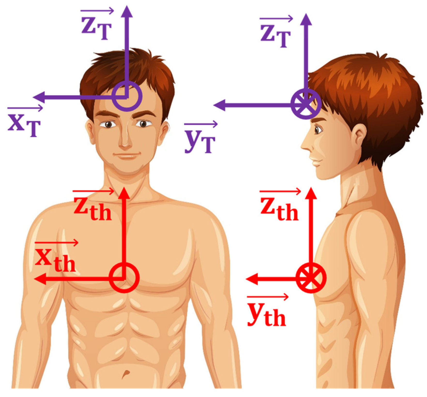
The range of motion of each volunteer was determined using local coordinate systems of the head and thorax, based on the various markers mentioned above (
Figure 3). The orientation of these reference frames is defined such that the
x-axis represents the flexion–extension axis, the
y-axis represents the lateral inclination axis, and the
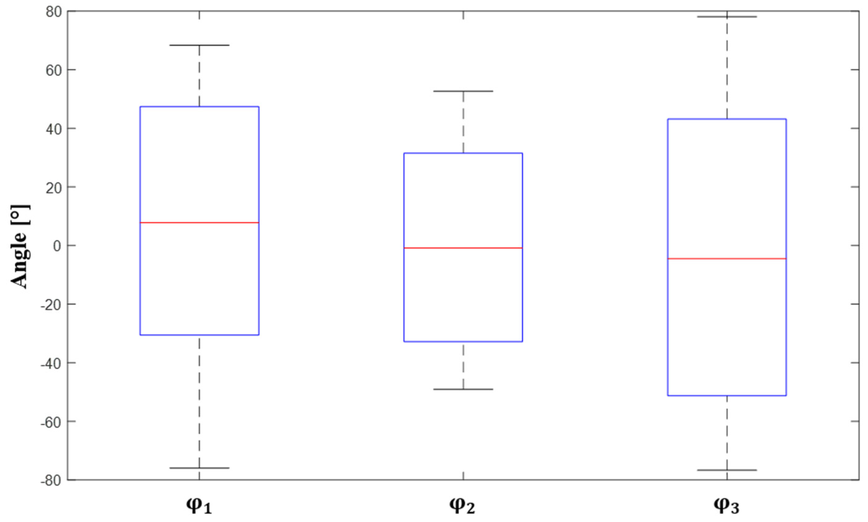
z-axis represents the axis of the head rotation. The orientation of the head in relation to the thorax according to the 3 anatomical reference planes, i.e., the range of motion of the cervical rachis, was computed using an approach developed using MATLAB software. For this purpose, the Cardan angles corresponding to the rotations around the
,
and
axes, respectively noted as
,
and
, were used. The computed Cardan angles are reported in
Figure 4.
These results agree with the range of motion reported in the literature [
17,
18], thus validating the protocol set-up during the measurement phase.
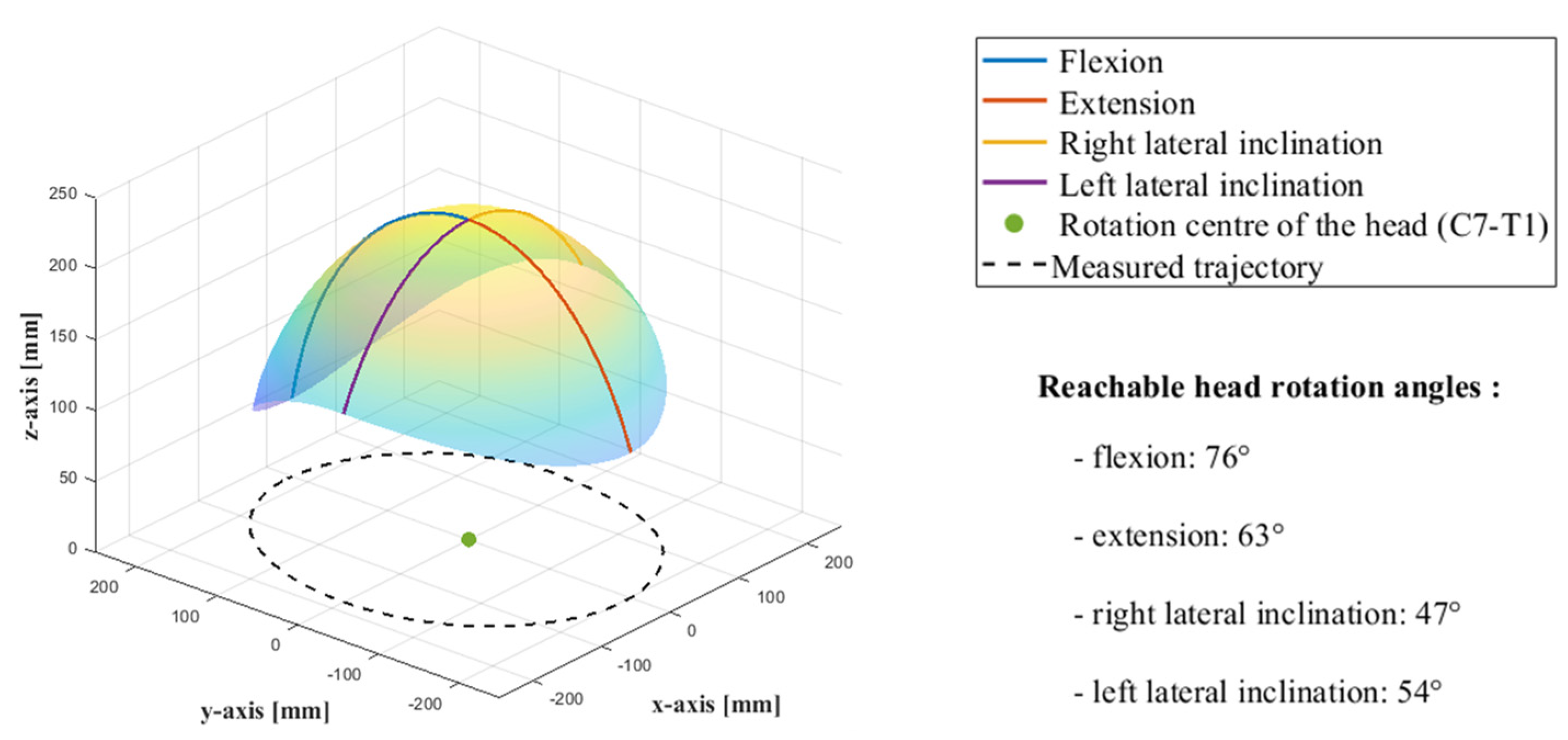
According to Kuo et al. [
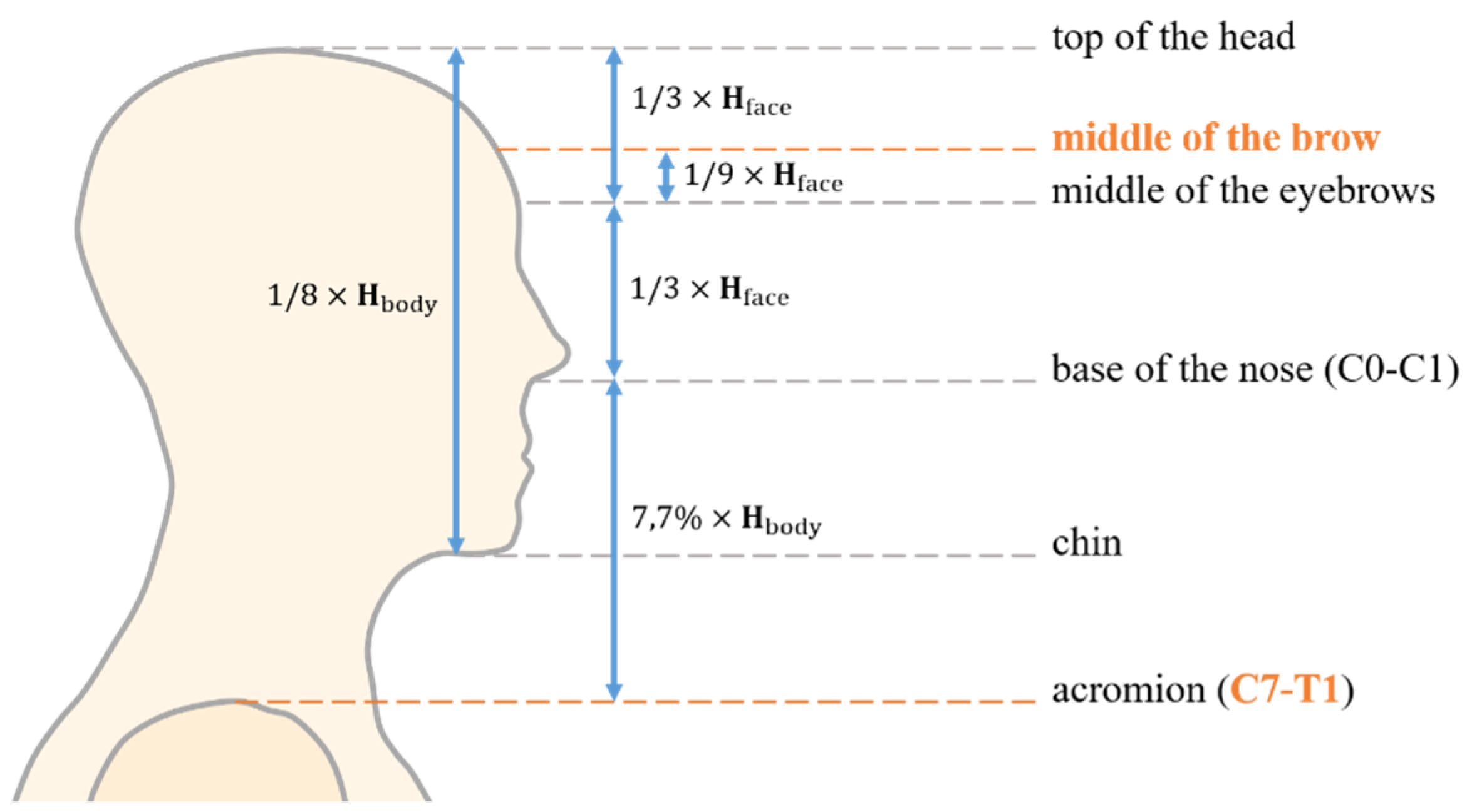
22], the instantaneous center of rotation of the head at the beginning of each movement is located at the joint between the seventh cervical vertebra and the first thoracic vertebra, i.e., at the base of the neck. However, during a flexion–extension movement, the center of rotation tends to move up the cervical spine. Its position was found to be close to the C5–C6 intervertebral joint. Conversely, during a lateral inclination, the center of rotation is located in the thoracic spine between the T2 and T3 vertebrae. In order to simplify the identification of the surface generated by the “center of the head” during its movement, a fixed center of rotation was considered, which is located at the base of the neck, between the C7 and T1 vertebrae.
Subsequently, the distance between this center of rotation and the “center” of the head, was determined based on a paper by Kuo et al. [
22], which states that this distance is, on averages about 7.7% of the body size (see
Figure 3).
In addition, the study of the proportion of the face makes it possible to identify the middle of the brow as shown in
Figure 5 [
23].
Therefore, the distance between the center of the head at the middle of the forehead and the base of the neck at the C7–T1 joint along the longitudinal axis can be determined as follows:
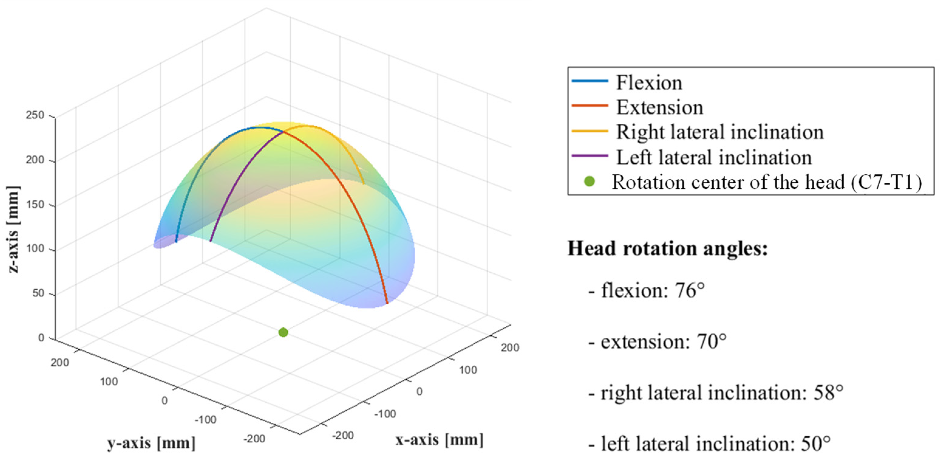
The resulting surface swept by the head center has thus a spherical shape as illustrated in
Figure 6.
3. CDPR Modeling
As shown through the results obtained by the motion capture, the head–neck joint has three rotations around the
,
and
axes as well as two translations along the
and
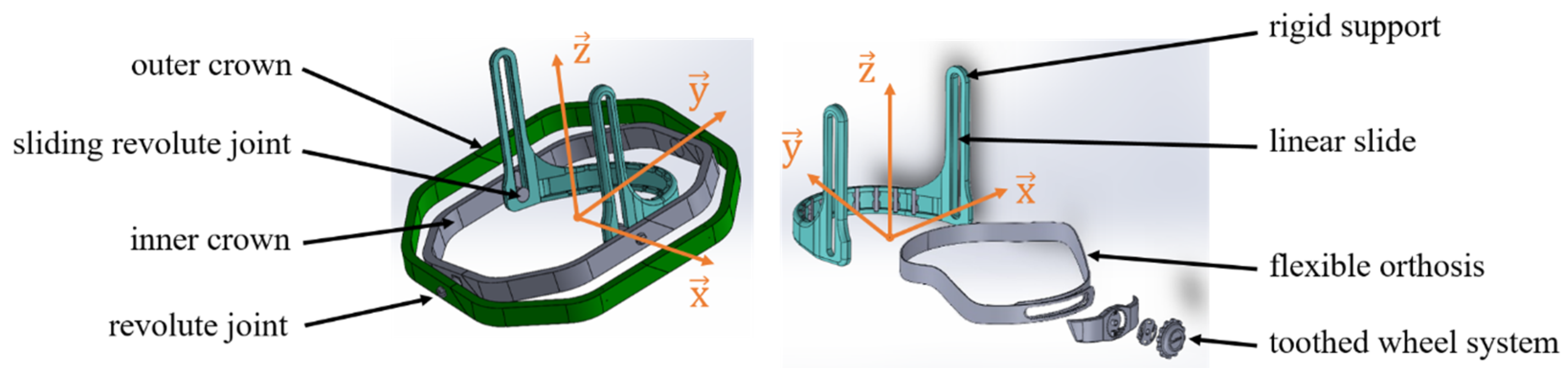
axes. Therefore, the robot requires 5 degrees-of-freedom (DoF) to drive the head. A new design of the end-effector is proposed to simplify the structure of the robot, which is based on a universal joint. Two main parts, i.e., an orthosis and an inner/outer crown, make up the end-effector (
Figure 7). The orthosis is the flexible part of the end-effector, which is used to adapt the size to fit different volunteers. In addition, between the inner crown and the flexible orthosis, the revolute connection is combined with a sliding joint.
This design of the end-effector aims at reducing the transmitted motions from the head to the outer crown to only two rotations and one translation. Indeed, the structure of the end-effector ensures that the two rotations around the
and
axes and the translation along the vertical axis (
) are not transmitted to the outer crown. [
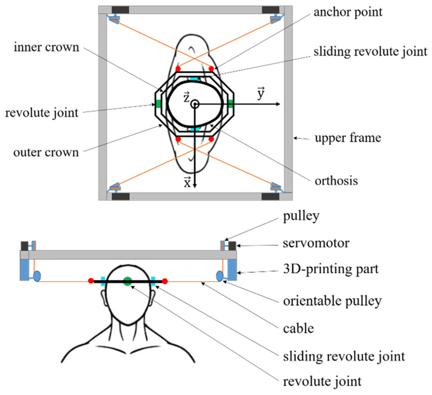
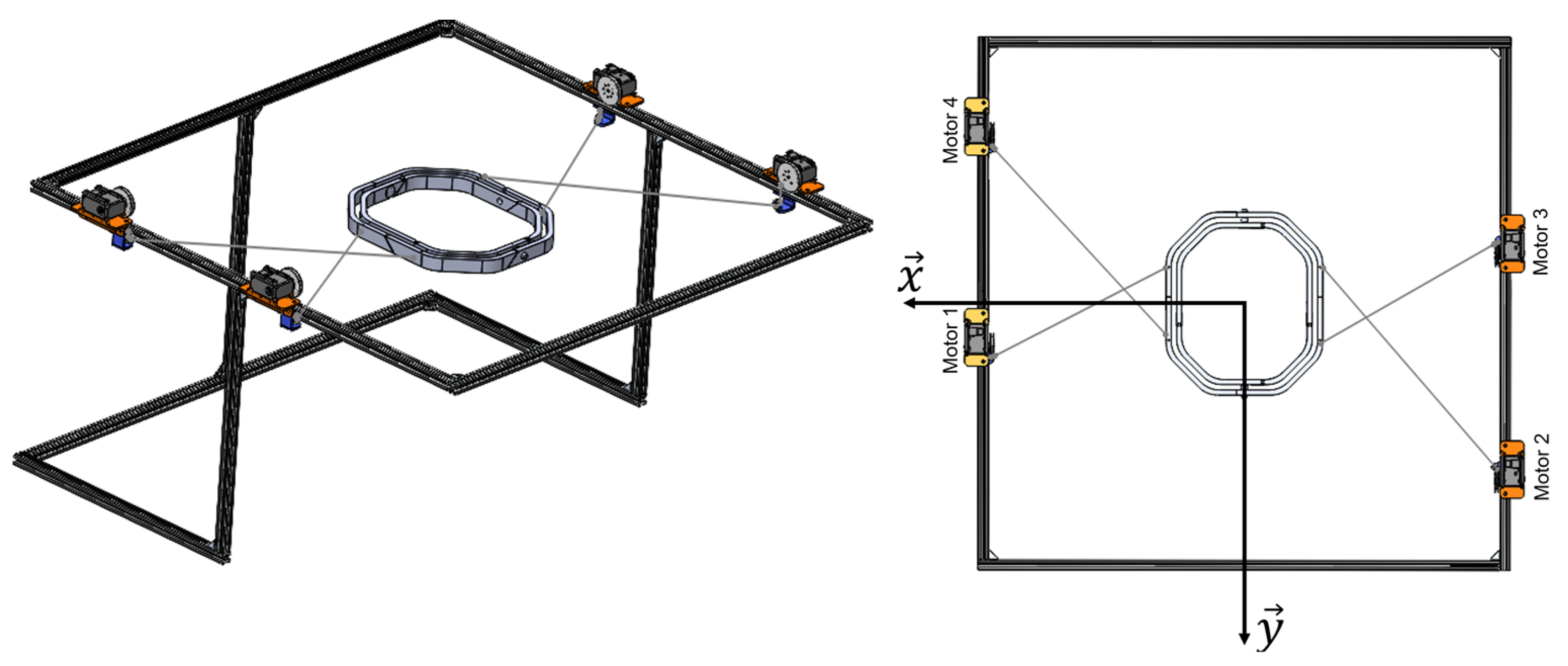
24]. In addition to extending the translational workspace as much as possible, these cables are crossed between the upper frame of a structure and the end-effector.
Figure 8 illustrates the CDRP with the double-crowned end-effector, the servomotors and the four cables.
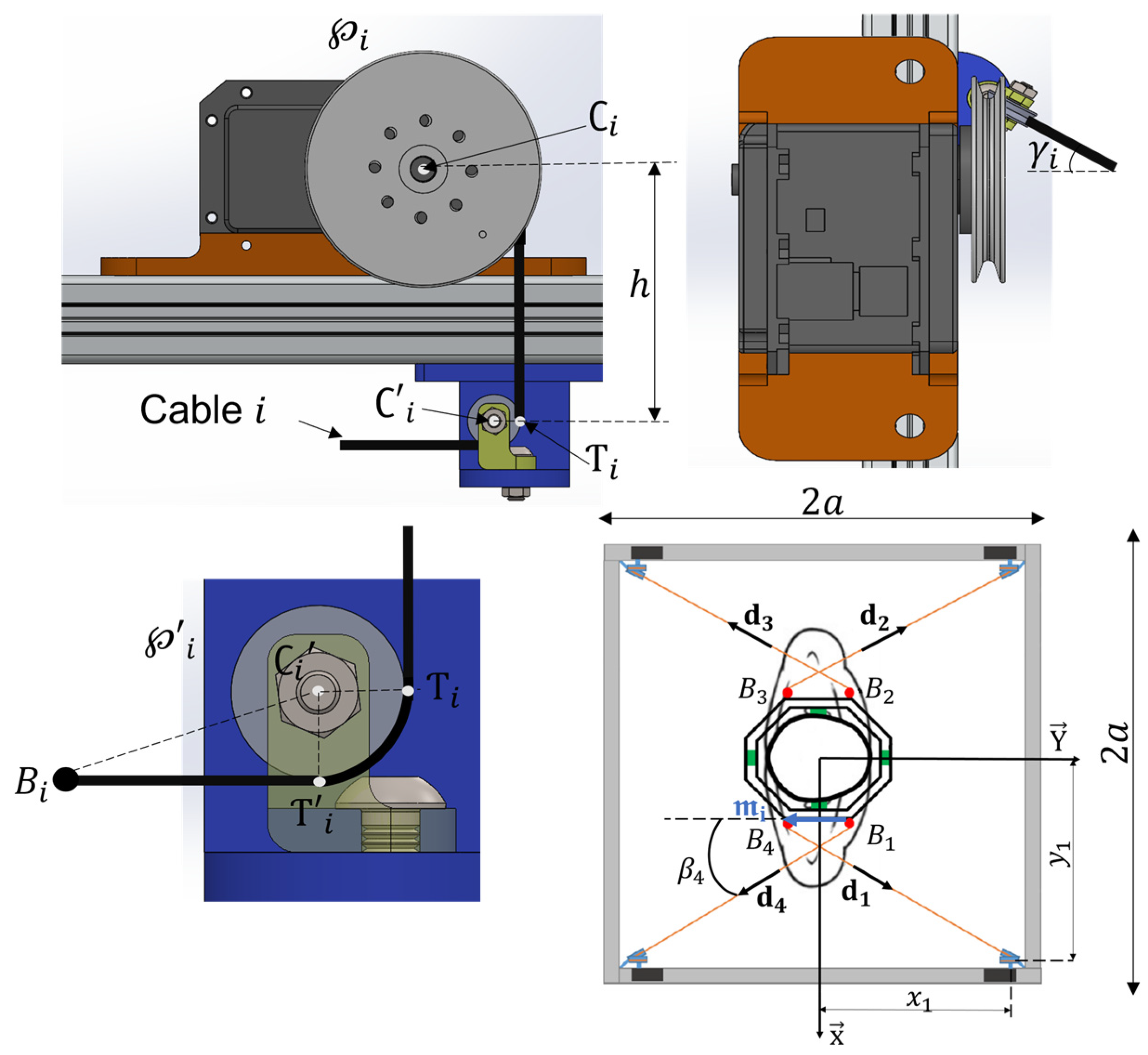
Thus, a cable-driven parallel robot with three DoF and four wires driven by servomotors and directed by orientable pulleys is considered in this paper. The set of geometric parameters, illustrated in
Figure 9 and used to define the kinetostatic model and thus the cable tensions, are expressed as follows:
where
is the vector containing the coordinates of point
, the center of the pulley
in the global frame
.
where
is the vector containing the coordinates of point
, the center of the guide pulley
in the global frame
is the radius of
,
is the vector containing the coordinates of the points
, and
is the angle defining the direction of the pulley
, expressed as follows:
is the unit vector along the
cable direction expressed as follows,
where
is the vector formed by the anchor points coordinates in the global frame
and
is the vector containing the coordinates of the points
(see
Figure 9).
Finally, the Jacobian matrix
can be expressed as given by Equation (6), where
is the rotation matrix between the global frame and a local frame attached to the robot end-effector and
is the vector containing the coordinates of the anchor point
in the local frame.
The dynamic model is developed with the assumption of neglecting the cable’s mass in order to compute the cable’s tension vector as detailed in Equations (7) and (8).
where
is the cables tension vector,
is the particular solution,
is the homogenous solution,
is the Moore-Penrose pseudo-inverse of the wench matrix
whereas
and
are the mass matrix, the Coriolis matrix, the end-effector pose vector, and the external forces vector applied to the moving platform, respectively;
and
are the weight, the moment of inertia, and the angular velocity of the end-effector, respectively; and
is the gravitational force. Finally,
is an arbitrary scalar [
25].
4. Formulation of the Optimization Problem
The aim of this section is to find the optimal location of each actuator, mounted on the robot fixed frame, that allows it to satisfy a set of criteria and constraints. The design vector
, given by Equation (9), is then formed by the parameters
and
, which define the coordinates of the center of the pulley
actuated by the
actuator as illustrated in
Figure 9.
Two criteria are considered for the optimization problem, namely the minimization of the cable’s tension
, so that the actuators provide the minimum torque in order to reduce the energy consumption, and the maximization of the end-effector dexterity
. These two criteria are formulated as follows:
where
is the number of points forming the trajectory,
is the tension of the cable
at the
position and
is a singular value of the Jacobian matrix.
A set of constraints must be respected in order to guarantee the robot’s best performance. For instance, the tension of each cable must be positive, since the cables can only pull and not push. This constraint is mathematically formulated as given in Equation (12).
The potential collisions between the cables and the end-effector are also considered. As illustrated by
Figure 9, the angle
between the edge of the end-effector, defined by the vector
, and the
cable, computed as given in Equation (13), must remain greater than a limit value in order to prevent unwanted interferences.
The last constraint concerns the locations of the actuators. They must be located on the edges of the robot’s fixed frame. In other words, at least one component of each actuator position vector (
or
) must be equal to
, which measures the robot’s fixed-frame side as represented in
Figure 8. Thereby the location of the actuators can be easily adjusted at different positions if other trajectories have to be implemented.
A penalty formulation is adopted to handle these problem constraints. This approach allows us to transform the given optimization problem into an unconstrained one by rejecting the undesirable candidates. Thus, the objective function
, given in Equation (15), can be formulated as the sum of the two functions
and
and the penalty functions
,
, and
. The coefficients
and
, whose sum is equal to 1, define a weight for each function.
where
,
and
are large scalars.
5. Optimization Results
The implementation of the CDPR modelling is performed using MATLAB software. The parameters used for the problem formulation are listed in
Table 1. The boundaries of each design parameter are summarized in
Table 2 and linked to the expected size of the robot fixed-square frame defined at
. The optimization process was performed using the Particle Swarm Optimization algorithm (PSO). The choice of this global search method was made based on its interesting characteristics compared with several other optimization techniques. It only needs simple operations, mainly the update of particle velocities and positions. In addition, it has a limited number of parameters to adjust, and their selection is widely discussed in the literature [
26,
27,
28]. Moreover, the influence of these parameters on the final solution quality is smaller compared with other types of algorithms [
28]. The optimal solution
found by the PSO algorithm as well as a comparison with the non-optimal solution, where the actuators are fixed at the corners of the robot fixed platform (see
Figure 8), are given in
Table 3.
In a second step, in order to judge the quality of the previously obtained solution, the gradient-based algorithm using the “fmincon” function of MATLAB was employed. This local search method requires an initial solution as a starting point. As an output, it gives either the same solution if the starting point is a global minimum, or another optimal solution if the starting point is a local minimum. In our case, the optimal design vector
given in
Table 3 was considered for the gradient algorithm as an initial guess. After executing the “fmincon” operations, the algorithm converges to the same starting point, which supports the selection of the PSO algorithm.
In a third step, in order to judge the robustness of the adopted solution, a One At a Time (OAT) sensitivity analysis [
29] based on the Monte Carlo method [
30] was investigated. This technique consists of varying the design vector parameters one by one, while fixing the others, according to a normal distribution (with a standard deviation equal to 1%) and separately assessing their impacts on the objective functions. A total of 5000 randomly generated perturbations was applied to each design variable. To evaluate whether these perturbations lead to unfeasible points, where the selected constraints cannot be satisfied, the two problem functions
and
are evaluated by computing the parameters
and
, respectively as follows:
where
is the number of unfeasible points.
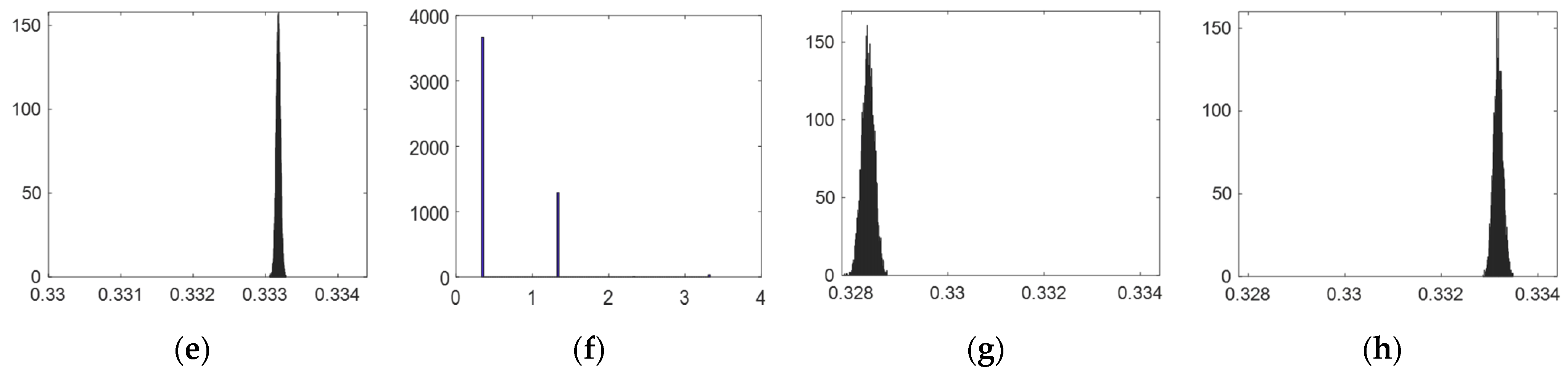
Since the functions and are normalized, their values vary from 0 to 1. Whenever or is greater then 1 after perturbation, it means that the constraints cannot be satisfied in some points given by (see Figure 15b).
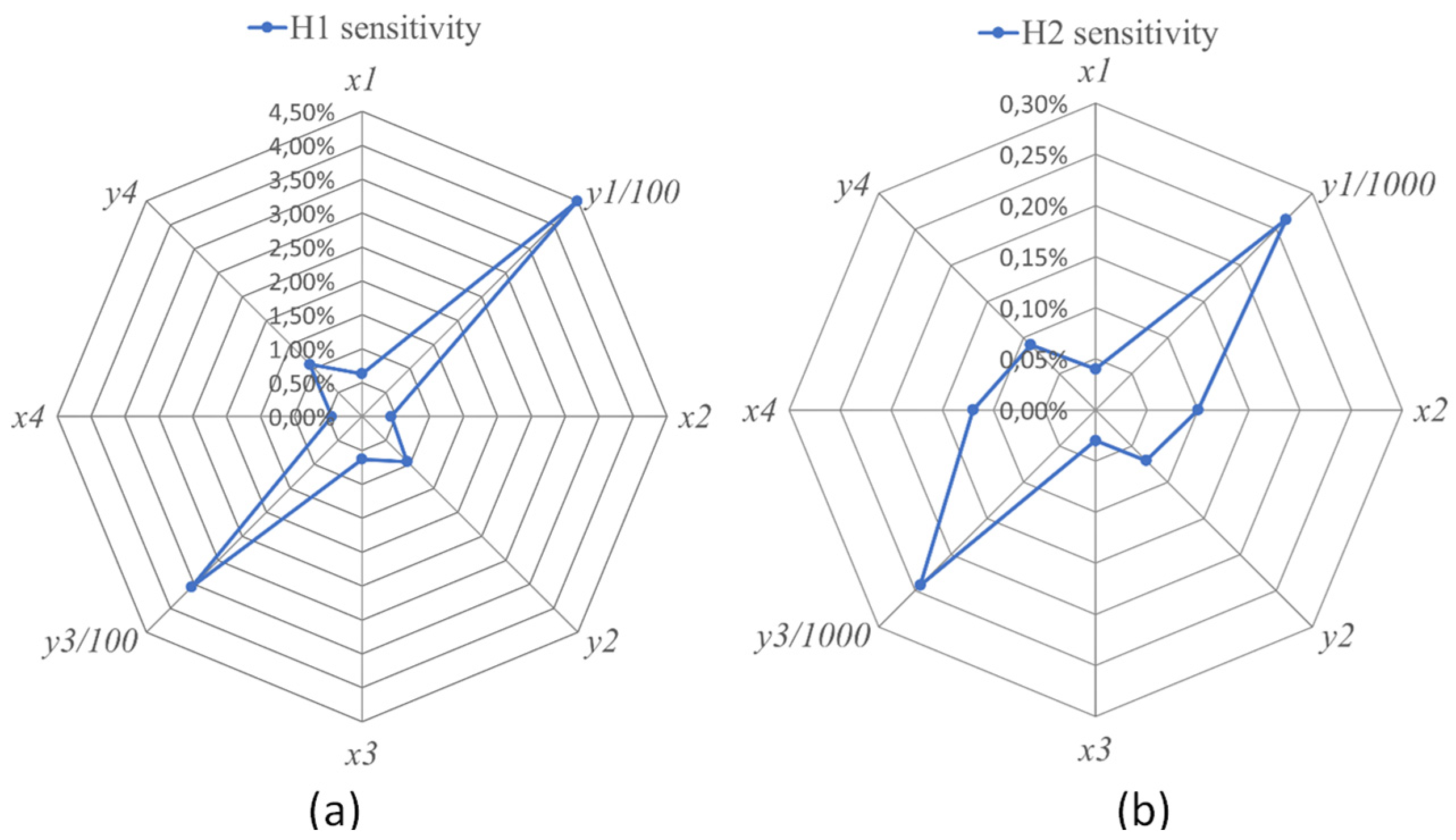
The sensitivity of each function, computed as given by Equation (21), measures the impact of each design variable perturbation [
31]. The results are summarized in
Table 4 and illustrated in
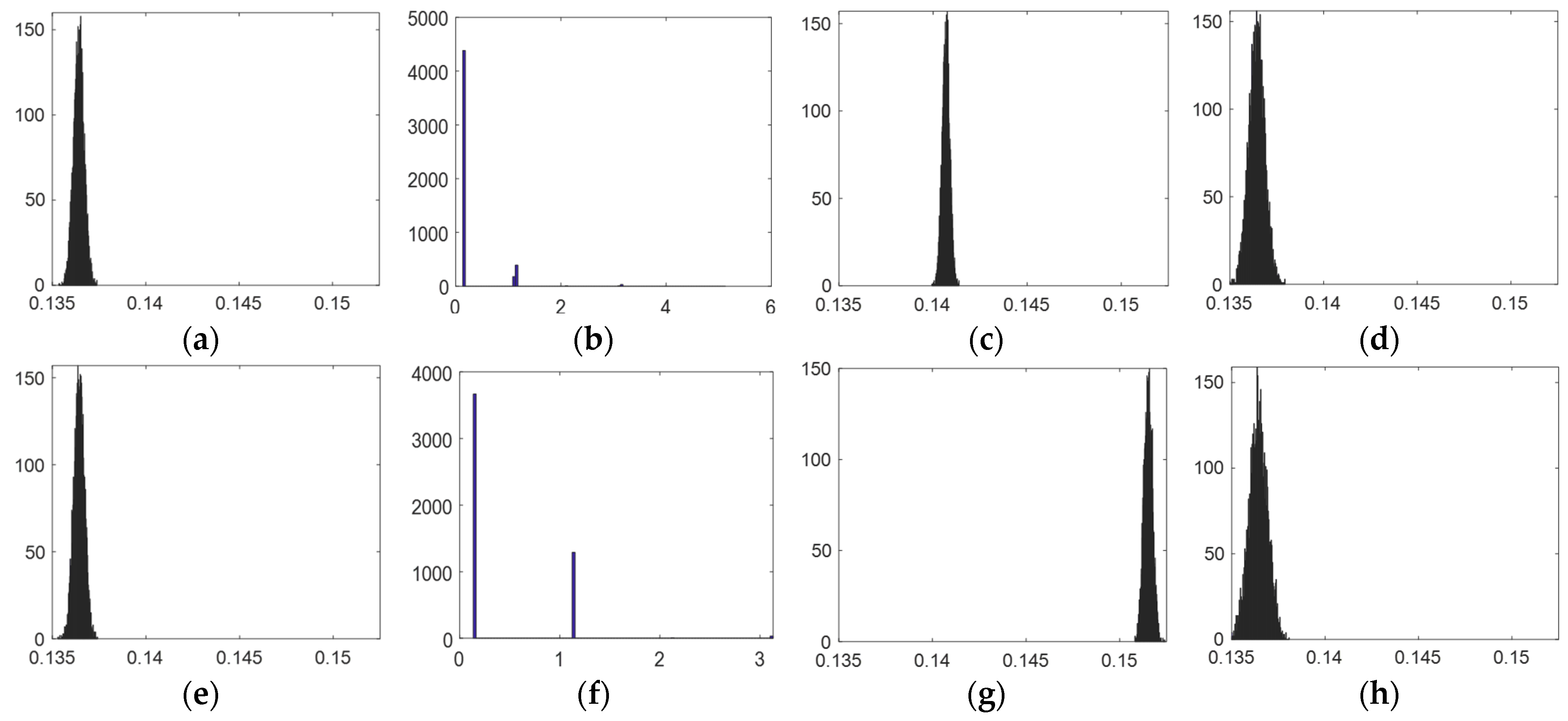
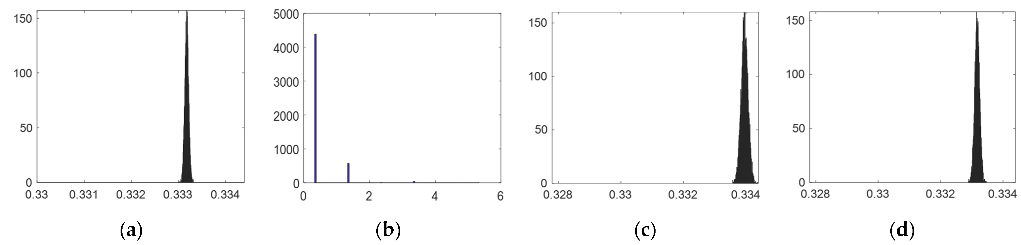
Figure 10. The evolution of
and
functions to the perturbations of all the design vector parameters are depicted in
Figure 11 and
Figure 12, respectively.
From
Table 3 and
Figure 11 and
Figure 12, the parameters
and
, related to the locations of the actuators 1 and 3, are more sensitive since their perturbations lead to a noticeable variation of the functions
and
, which is caused by unfeasible points (see
Figure 11b,f and
Figure 12b,f). Particular precision while fixing these two actuators is then needed. The positioning of the rest of the variables is more tolerant since they do not have an observable impact on the problem criteria.
A representation of the obtained optimal robot structure is illustrated in
Figure 13 with the optimal design vector
given in
Table 4.
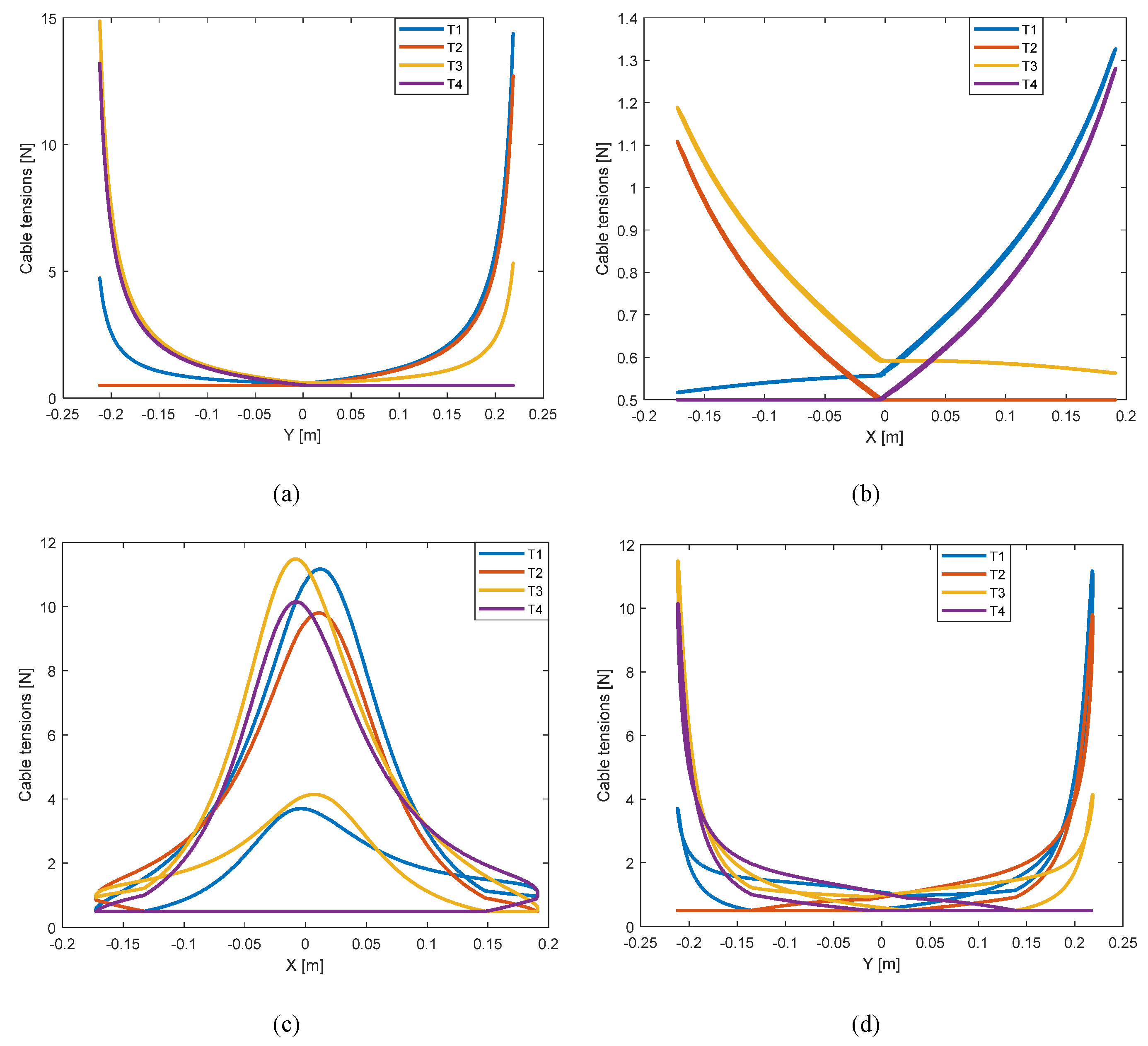
Figure 14 displays the cable tension variations along the three prescribed trajectories. The peaks are observed when the center of the end-effector is close to the extremities of the statically accessible workspace. This latter is the set of poses where the four cable tensions are positive. This workspace is depicted in
Figure 15a. Finally, the dexterity distribution along the robot workspace is illustrated in
Figure 15b.
6. Experimental Validation
In order to carry out an experimental validation, a robot prototype, presented in
Figure 16 was built. The actuated pulleys and the end-effector were 3D printed. Dynamixel MX-106T servomotors were used to actuate the four Dyneema wires of the CDPR. The position of each actuator was adjusted according to the optimal design vector given in
Table 4.
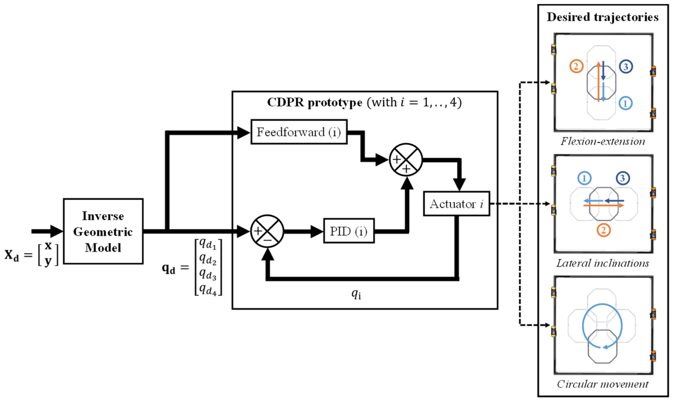
For the control of the CDPR, a position control mode was adopted. In order to determine the desired angular position of each actuator
, which is required to follow the desired cartesian trajectory
, the inverse kinematic model of the CDPR was used, i.e.
. To reach the desired angular positions, the internal controller of the Dynamixel MX-106T combines the effects of both: a classical PID controller that corrects the deviation of the trajectory based on the feedback given by the encoder, and a feedforward controller that compensates the internal disturbances and anticipates the dynamics of the reference trajectory, as shown in
Figure 17. For the PID control gains, the pre-tuned values given by the constructor for the position control mode were used, i.e., I-gain = 0, D-gain = 0 and P-gain = 6.64.
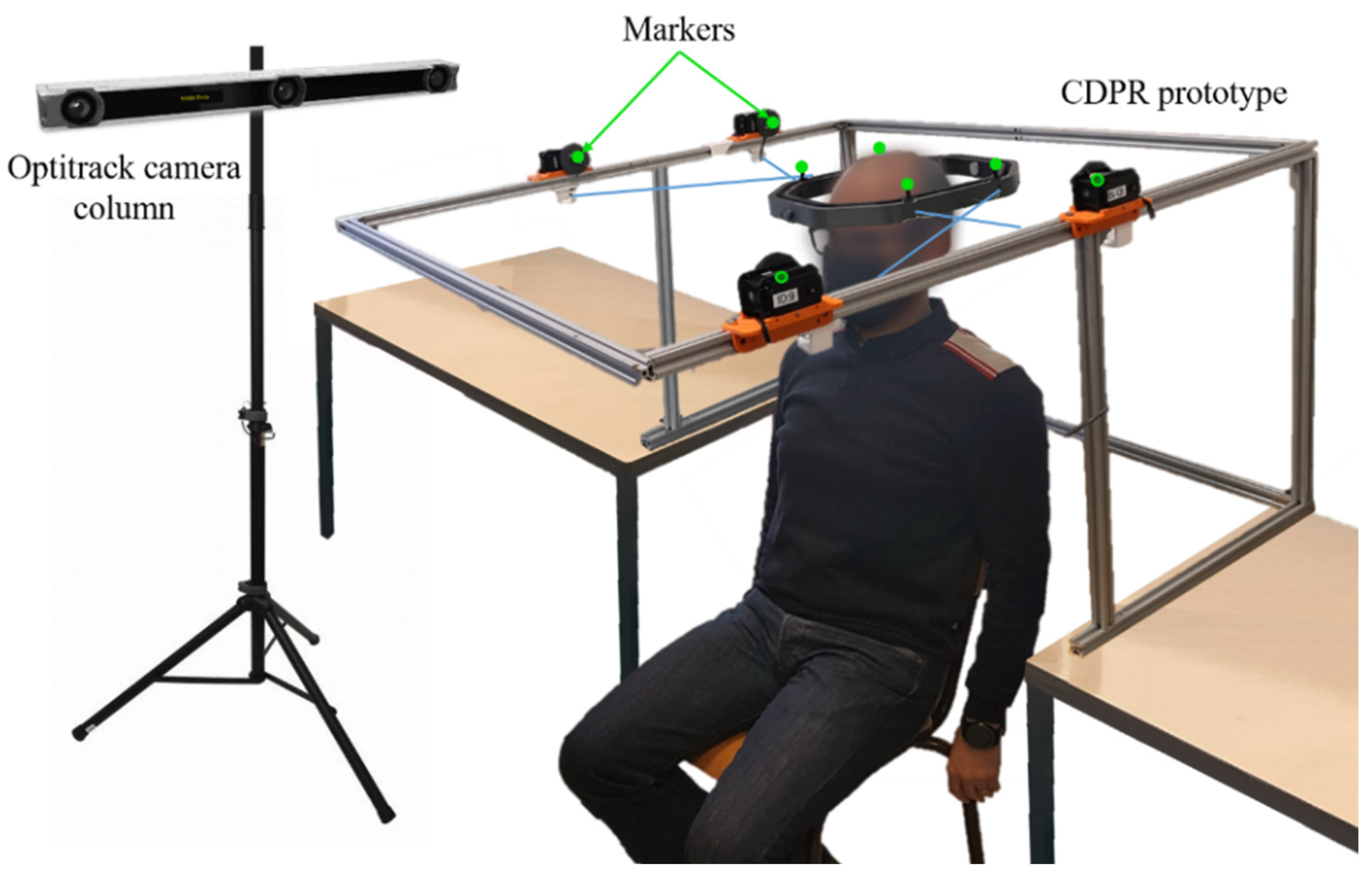
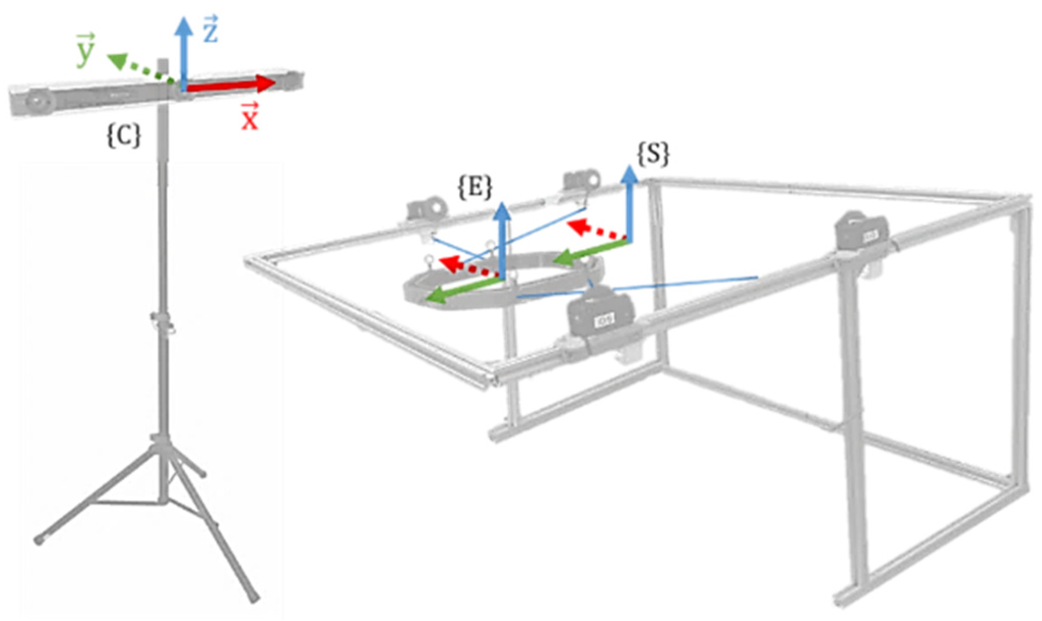
A motion-capture system was then utilized to track the end-effector poses along the three prescribed movements (flexion–extension, lateral inclinations and circular movement) and these results were compared with the desired behavior. As shown in
Figure 18, an Optitrack V120: Trio camera column and eight passive reflective markers—four on the center of the actuated pulleys and four on the anchor points of the end-effector—were required. From the collected data, three reference frames were defined as shown in
Figure 19:
is the reference frame of the Optitrack cameras,
is related to the center of the end-effector and
is the frame association with the center of the structure upper frame.
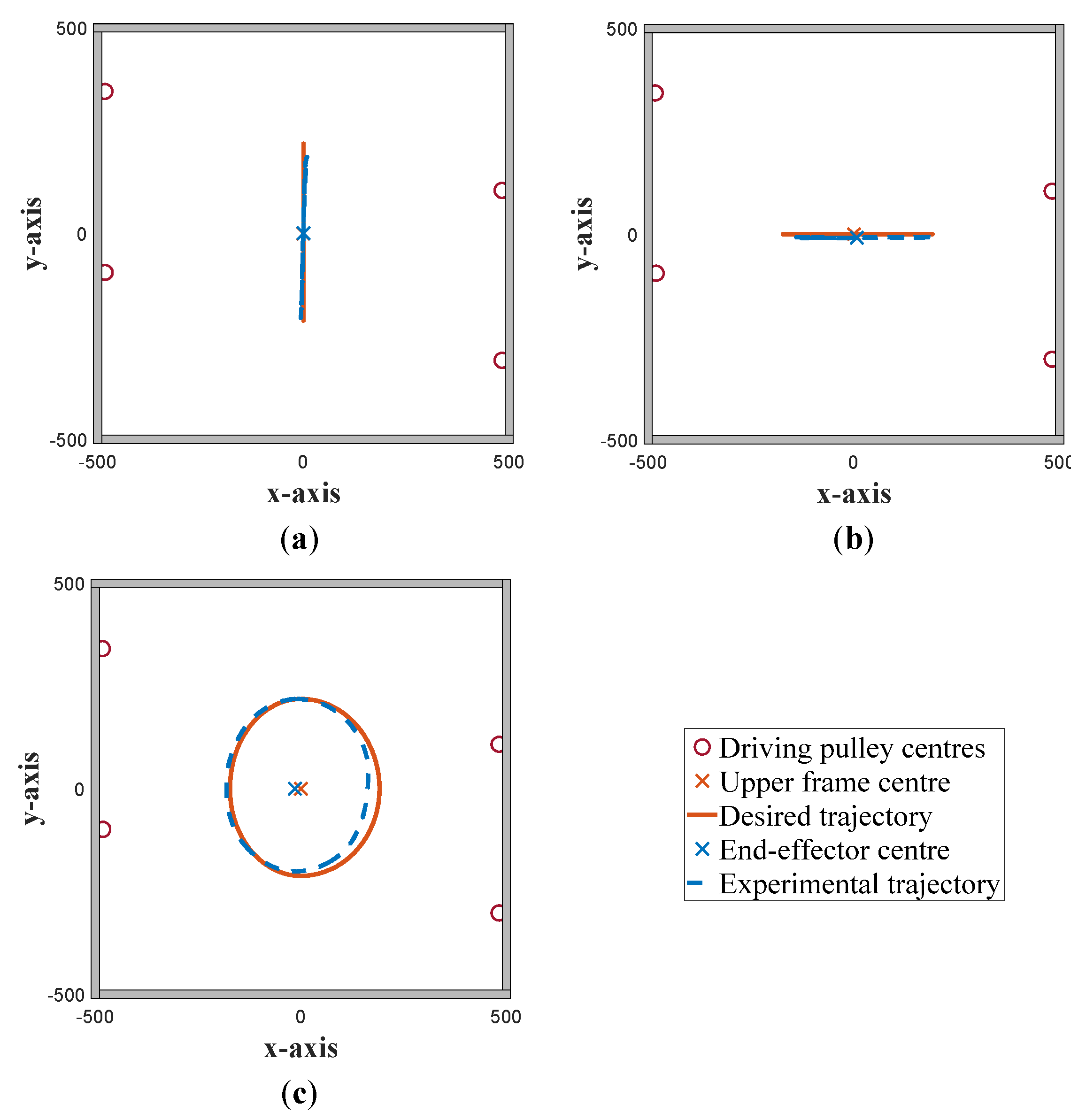
Figure 19 illustrates the obtained deviations between the performed trajectories and the targeted ones.
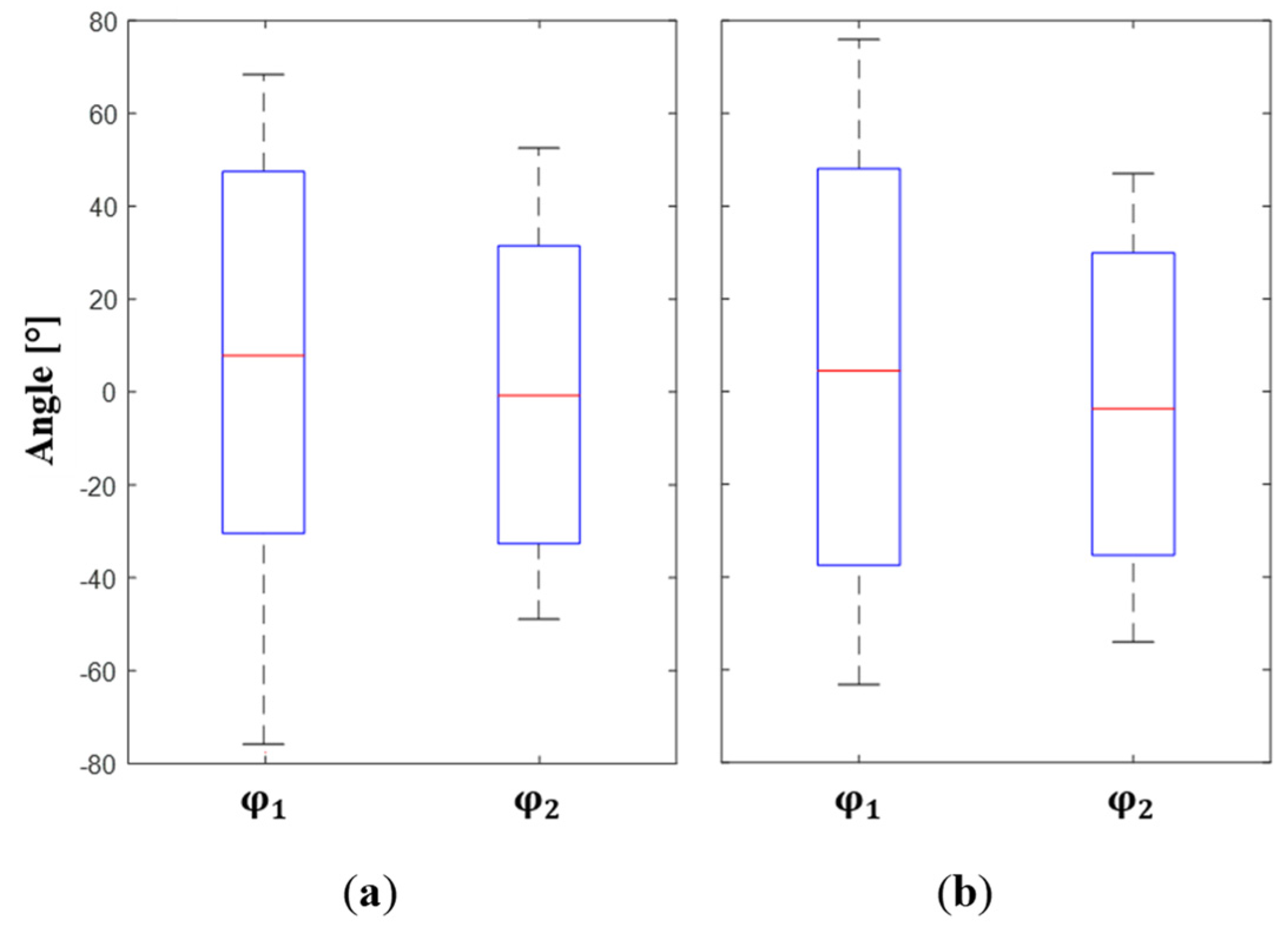
Subsequently, knowing the position of the end-effector center and defining a rotation center of the head identical to the one established following the motion capture on volunteers (see
Section 2), the angular amplitudes of flexion–extension (
) and lateral inclination (
) equivalent to the displacements of the end-effector were computed. The obtained results are given in
Figure 20. Analyzing the boxplots, we can observe that the medians for angular amplitudes
and
, respectively, are all at the same level.
In addition, the surface reachable by the head depending on the trajectories performed by the end-effector is shown in
Figure 21.
Several external and internal factors can explain the observed deviations from the desired angular amplitudes (see
Figure 6). Firstly, the uncertainties can be related to the positioning of the eight markers, which may lead to errors while calculating the end-effector center position with respect to the structure frame (see
reference frame in
Figure 18). This can therefore lead to errors when determining the equivalent angular amplitudes of the head with respect to the end-effector displacements. Secondly, errors specific to the prototype can influence its functioning such as cable behavior, imprecision on the anchor points and servomotor positions.
Through the performed experimentation, it can be concluded that comfort and ease of use are ensured by the proposed solution, which are two important factors that can judge the success of such a new device. Furthermore, the experimental results conducted using a protocol similar to the one used with volunteers showed the feasibility of the proposed solution and the capability of the rehabilitation device to cover the full natural range of the head movements. The passive head–neck joint training performed by the CDPR is satisfactory and meets the design requirements and task specifications of Head–Neck joint amplitudes.
7. Conclusions
The present paper discussed a novel rehabilitation device based on a cable-driven parallel robot (CDPR). The proposed design has several advantages compared with existing devices in terms of workspace and safety. Indeed, the other head–neck joint rehabilitation systems present a limited workspace and are made of rigid links, which completely constrains patient movements. In this context, the first step of the work consisted of analyzing the cervical spine motion using a motion-capture system. The recorded trajectories allowed us to delimit the required workspace of the CDPR necessary to perform the desired rehabilitation movements. An optimization problem was formulated and the structure presenting the optimal cable tension and dexterity distribution was identified. To reduce energy consumption and to prevent the collision between the cables and the end-effector, a set of constraints were introduced. Once the optimal solution was selected, an experimental validation was carried out on the built prototype. A second motion-capture experiment was then conducted to assess the behavior of the optimal robot structure while performing the prescribed movements. A quantitative evaluation of the prototype reliability was achieved by computing different position errors which showed promising results.
From a future perspective, the robot modelling will be adapted to allow 3D trajectories to be performed and then to accurately follow the head motion. Furthermore, other control modes can be implemented to provide different degrees of assistance to the patient, mainly the assist-as-needed mode where the external forces applied by the user are taken into account.
The main required future research steps will focus on results with better repeatability, fewer mistakes, less rework and redesign, faster time to market, improved competitiveness, and lower production costs. These steps comprise the path until the CDPR for movement training of the head–neck joint can be validated with real patients and become a certified medical robot ready for the market.


 ,
, 


