Article

Transformable Wheelchair–Exoskeleton Hybrid Robot for Assisting Human Locomotion

by
Ronnapee Chaichaowarat
*,
Sarunpat Prakthong
and
Siri Thitipankul
International School of Engineering, Chulalongkorn University, 254 Phayathai Road, Pathumwan, Bangkok 10330, Thailand
*
Author to whom correspondence should be addressed.
Robotics 2023, 12(1), 16; https://doi.org/10.3390/robotics12010016
Submission received: 11 December 2022 / Revised: 15 January 2023 / Accepted: 16 January 2023 / Published: 18 January 2023
(This article belongs to the Special Issue Human Factors in Human–Robot Interaction)

Abstract

:
This paper presents a novel wheelchair–exoskeleton hybrid robot that can transform between sitting and walking modes. The lower-limb exoskeleton uses planetary-geared motors to support the hip and knee joints. Meanwhile, the ankle joints are passive. The left and right wheel modules can be retracted to the lower legs of the exoskeleton to prepare for walking or stepping over obstacles. The chair legs are designed to form a stable sitting posture to avoid falling while traveling on smooth surfaces with low energy consumption. Skateboard hub motors are used as the front driving wheels along with the rear caster wheels. The turning radius trajectory as the result of differential driving was observed in several scenarios. For assisting sit-to-stand motion, the desired joint velocities are commanded by the user while the damping of the motors is set. For stand-to-sit motion, the equilibrium of each joint is set to correspond to the standing posture, while stiffness is adjusted on the basis of assistive levels. The joint torques supported by the exoskeleton were recorded during motion, and leg muscle activities were studied via surface electromyography for further improvement.

1. Introduction

In most regions around the world, the population aged 65 and older is growing faster than the total population. Physical deterioration is inevitable with age. Mobility improvements allow the elderly and people with disabilities to access jobs, education, and healthcare and keep their societal roles. Wheelchairs are common personal assistive devices for individuals with locomotor disabilities. The lever propelling mechanism was applied to improve the performance of manual wheelchairs [1]. Although traveling by wheels on rigid frames is stable, safe, and consumes low energy, steps and stairs remain critical obstacles. Elevators and slopes for reducing barriers to locomotion cannot be provided in all public facilities, and their use is sometimes prohibited during emergencies. In addition to improving wheelchair-friendly infrastructure, reducing the limitations of wheelchairs in the presence of obstacles is challenging. Although manual and power-assisted stair-climbing wheelchairs [2,3,4,5] have been developed thus far, their structures remain too bulky to be carried on vehicles by users.
Wheelchair users are usually constrained to the sitting posture, which is sometimes inconvenient in environments designed for people capable of standing. For elderly persons [6] and patients with Parkinson’s disease or with spinocerebellar degeneration [7], the standing posture provides not only great independence but also has medical advantages in terms of bone metabolism, blood circulation, and inflammation prevention. Upright wheelchairs [8,9] were developed as alternatives. Standing mobility devices [10] with passive exoskeletons using gas springs assist users with lower limb motor disabilities in sitting down or standing up from an ordinary chair and maintaining voluntary postural transitions. However, wheelchairs that can climb up stairs or obstacles in standing posture and allow free walking have not been mentioned in the literature. The wearable robot suit HAL [11] can expand the physical capabilities of healthy people. The powered exoskeletons Ekso [12], ReWalk [13], and REX [14] were developed for rehabilitating and assisting the daily locomotion of people with disabled lower limbs. These exoskeletons can assist patients in walking and keeping their limbs active. However, users must use crutches to maintain their balance with their upper limbs. In addition, humans and exoskeletons consume considerable energy during walking [15]. Thus, the distance of movement is limited by battery capacity. The walking performance and safety of robots also strongly rely on control systems and the quality of gait phase detection.
The concept of a detachable lower-limb exoskeleton from an adjustable-height wheelchair was proposed to combine the advantages of traveling by wheel over long distances and by walking exoskeletons over complex terrains [16]. However, users cannot carry full-sized wheelchairs for on-demand sitting. The concept of hybrid assistive wheelchair–exoskeleton robots with a reduced number of actuators was proposed [17]. Nevertheless, its design cannot guarantee the balance of the user during the configuration transition. A large joint torque was also required to support the chair leg in equilibrium to maintain the distance between the front and rear wheels in the sitting configuration. The reconfigurable mechanism was designed for wheelchair–exoskeleton hybrid robots [18] to secure the user’s balance during sit-to-stand and stand-to-sit motions without requiring additional support from the upper limbs. Given that chair legs are not included in the design, the moment due to the weight of the human body was mainly supported by the linear actuators with high gear ratios. The dynamic load due to road vibration was transmitted to the gear. The non-backdrive mechanism is not preferred in consideration of safe physical human–robot interaction [19,20].
The biomechanics of sit-to-stand motion in elderly persons was studied [21] on the basis of the kinematic data collected using video and the ground reaction force measured with a force plate, along with muscle activity monitored with surface electromyography (EMG). The muscle activities of elderly fallers and non-fallers during sit-to-stand motion were compared [22]. The joint torque and power consumption during motion were estimated on the basis of the human model [23]. The kinematic model of a lower-limb exoskeleton was proposed for determining the joint angle and position of the leg during movement [24]. The active impedance control of a lower-limb exoskeleton with the human joint torque observer was proposed for sit-to-stand movement [25]. The control method of a wearable robot for the sit-to-stand and stand-to-sit transfers of patients with spinal cord injuries was presented [26]. The concept of a passive gravity-balanced assistive device using a counterweight and springs connected to the auxiliary parallelograms considering the hip, knee, and ankle torques required against joint angles was proposed [27].
We propose a novel wheelchair–exoskeleton hybrid robot that can transform between sitting and standing configurations as an alternative compact and lightweight personal mobility vehicle for the elderly and people with disabilities. The lower-limb exoskeleton uses motors with planetary gears to support the hip and knee joints. Meanwhile, the ankle joints are passive. The left and right wheel modules can be retracted to the lower legs of the exoskeleton to prepare for walking. The chair legs are designed to form a stable sitting posture to avoid falling while traveling on smooth surfaces by using two skateboard hub motors as the front driving wheels. In this work, the simplified human model was derived in accordance with wheelchair parameters to simulate the hip and knee moments required during a sit-to-stand motion to select the actuators driving the exoskeleton joints without requiring an additional high-force actuator to support the motion. The prototype of the wheelchair–exoskeleton hybrid robot was built and tested. For assisting sit-to-stand motion, the desired joint velocities are commanded by a user while the damping of the motors is set. For stand-to-sit motion, the equilibrium of each joint is set to correspond to the standing posture, whereas stiffness is adjusted on the basis of the assistive level. During tests, the exoskeleton joint torques were recorded, and leg muscle activities were studied via surface EMG. The turning radius trajectory as the result of differential driving in the wheelchair mode in several scenarios was observed.
Section 2 introduces the design concept of the wheelchair–exoskeleton hybrid robot and derives the human model for simulating the joint torques during sit-to-stand motion. Section 3 shows the built prototype and explains the control system. Section 4 describes the experimental setup and discusses the results of the sit-to-stand and stand-to-sit experiments. Section 5 presents the results of differential driving tests. Section 6 summarizes the key findings and ongoing efforts.

2. Concept of the Wheelchair–Exoskeleton Hybrid Robot

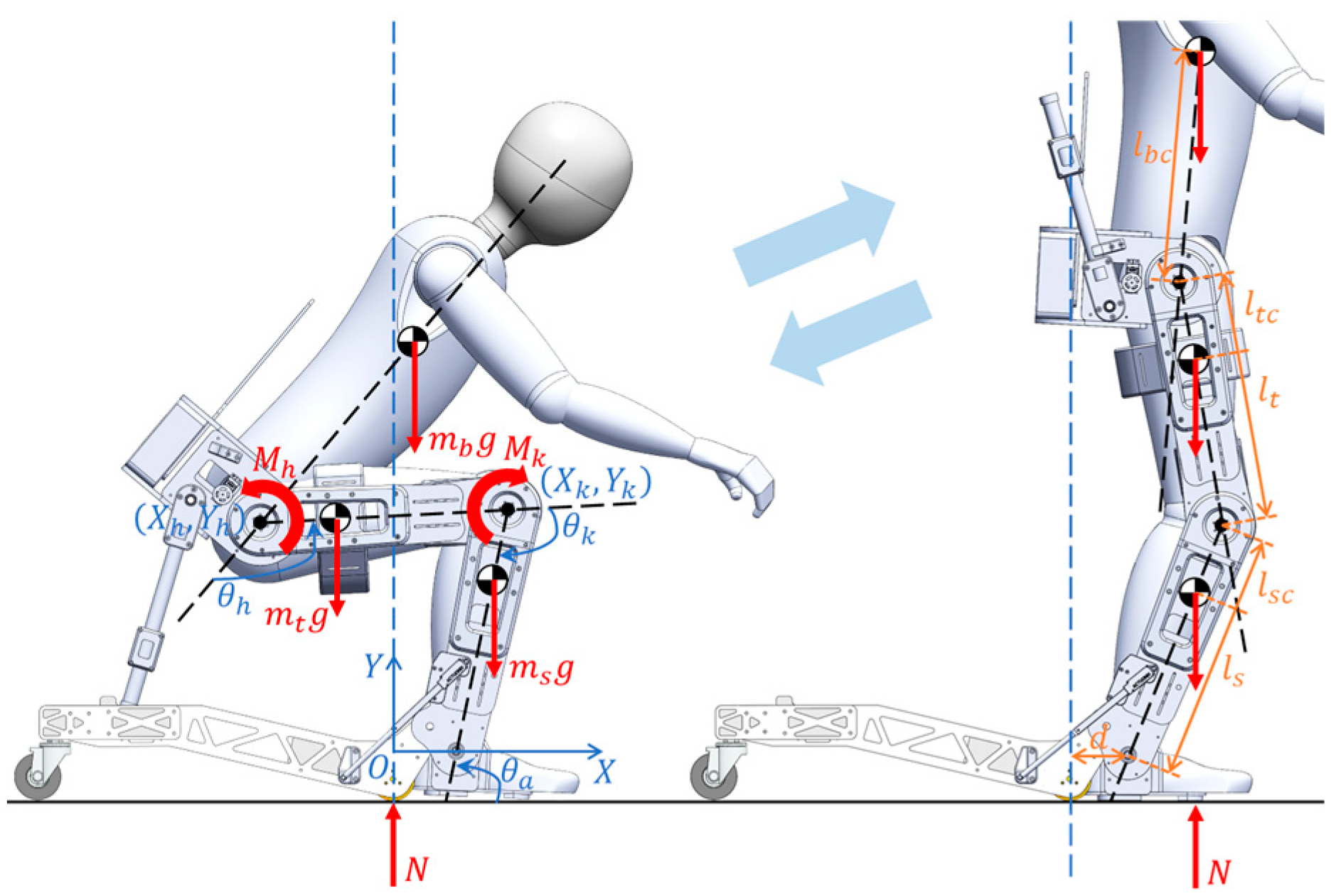
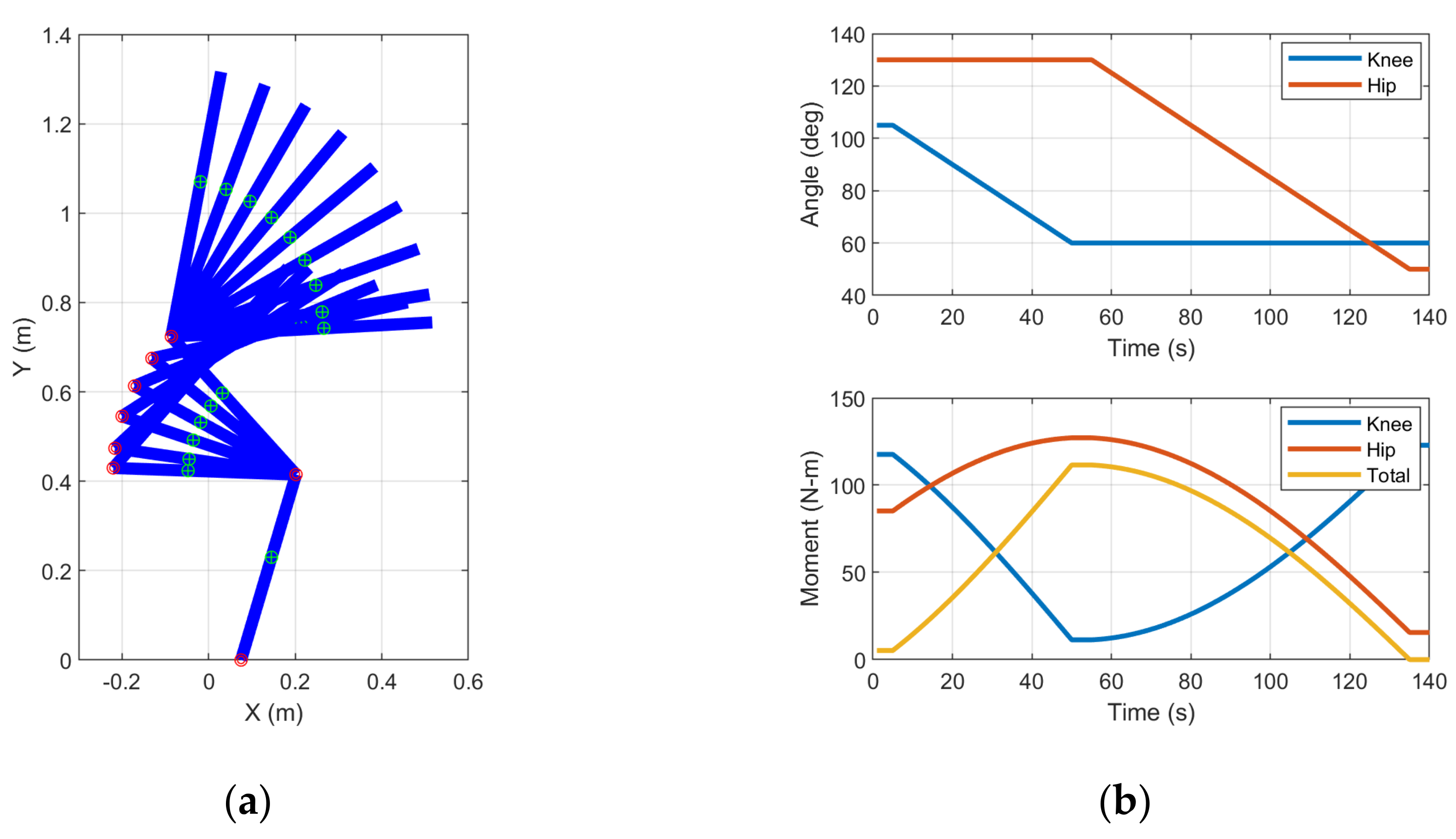
2.1. Biomechanics of Sit-to-Stand Motion

The wheelchair–exoskeleton hybrid robot can transform from sitting to standing configurations on the sagittal plane, as shown in Figure 1. Trunk flexion (increasing the hip angle θ h ) is necessary to move the body’s center of gravity forward over the front wheels (pivot point) to prepare for standing up. The ground-contacting point is shifted from the rear caster wheels to the feet during this transition. By creating the knee extension moment M k , the whole body is lifted upward. As the knee is extended (the knee angle θ k decreases) adequately, the hip extension moment M h is required to align the upper body in an upright posture (the hip angle decreases). The ground reaction force N is now located anterior to the front wheels to maintain the equilibrium in the standing configuration. The pair of chair legs is rotated upward, and the left and right wheel modules are retracted to prepare for walking.

2.2. Estimation of Knee and Hip Moments from the Human Model

By considering the front wheel as the reference of the horizontal position, as shown in Figure 1, the offset d measured to the ankle joint is assumed to be constant at 75 mm during sit-to-stand motion. The horizontal positions of the shank’s center of gravity X s c , the knee joint X k , the thigh’s center of gravity X t c , the hip joint X h , and the upper body’s center of gravity X b c are respectively written as equations:
X s c = d + l s l s c c o s θ a ,
X k = d + l s c o s θ a ,
X t c = X k + l t l t c c o s θ a + θ k ,
X h = X k + l t c o s θ a + θ k ,
X b c = X h + l b c c o s θ a + θ k θ h .
The summation of moments about the pivot point (or the front wheels) required to prevent falling backward should satisfy the condition as the equation:
m s g X s c + m t g X t c + m b g X b c > 0 ,
indicating that the total moment is in the clockwise direction. In consideration of the links over the knee joint, the knee extension moment sufficient to maintain the static equilibrium is derived as the equation:
M k = m t g X t c X k m b g X b c X k .
In consideration of the link over the hip joint, the hip extension moment that is sufficient to maintain the static equilibrium is derived as the equation:
M h = m b g X b c X h .
For the estimation of the knee and hip extension moments required during sit-to-stand motion, our simulation is simplified by assuming that the hip angle is constant at 130°, whereas the knee extension angle varies from 105° to 60°. Subsequently, the knee angle is assumed to be constant at 60°, whereas the angle of hip extension varies from 130° to 50° at a very low speed to avoid considering the dynamics of motion. The ankle angle is assumed to be constant at 73° throughout the transition period. According to the sitting geometry in Figure 1, the existence of the wheel modules does not allow moving the feet behind to shift the ground reaction force backward as in normal sit-to-stand motion [28,29,30]. Bending the trunk with the hip flexion larger than usual is necessary. The link parameters used in our simulation are shown in Table 1, in which the locations of the links’ center of gravity are applied from [31], and the total mass of human M is 73 kg.
The trajectories of the shank, thigh, and upper body during sit-to-stand motion are simulated, as shown in Figure 2a. The shank is fixed with a constant ankle angle. The knee is extended with a constant hip angle. Then, the hip is extended with a constant knee angle. The variation in the body’s CG position against the joint angles is observed. The body’s CG must be located anterior to the front wheels ( X = 0) such that the total moment computed via Equation (6) is always positive to prevent falling backward. The yellow plot in Figure 2b shows that the risk of falling backward is high (small magnitude of the total CW moment) when the upper body’s CG is posterior to the ankle. The ground reaction force required beneath the feet to counter this total moment depends on the extent that the legs and body’s CG are shifted forward during sit-to-stand motion.
Figure 2b shows that the maximum knee moment (approximately 120 N·m) is required during the early phase of knee extension when the thigh and body’s CG are significantly posterior to the knee joint. A high magnitude of the knee moment is required again during the latter phase of hip extension when the body is upright, and the body’s CG is posterior to the knee joint. The maximum hip moment (approximately 130 N·m) is required at the latter phase of knee extension when the upper body’s CG is extremely anterior to the hip joint. Notably, the maximum knee moment can be reduced if the motion is started from a low knee angle. For example, approximately 100 N·m is sufficient if the knee begins extending from 95° instead. In addition, the maximum hip moment is reduced because the hip flexion to move the body’s CG forward has a small angle. If the arms’ weight is also considered, the knee and hip extension moments will be reduced in accordance with the limbs’ CG.

3. Wheelchair–Exoskeleton Hybrid Robot

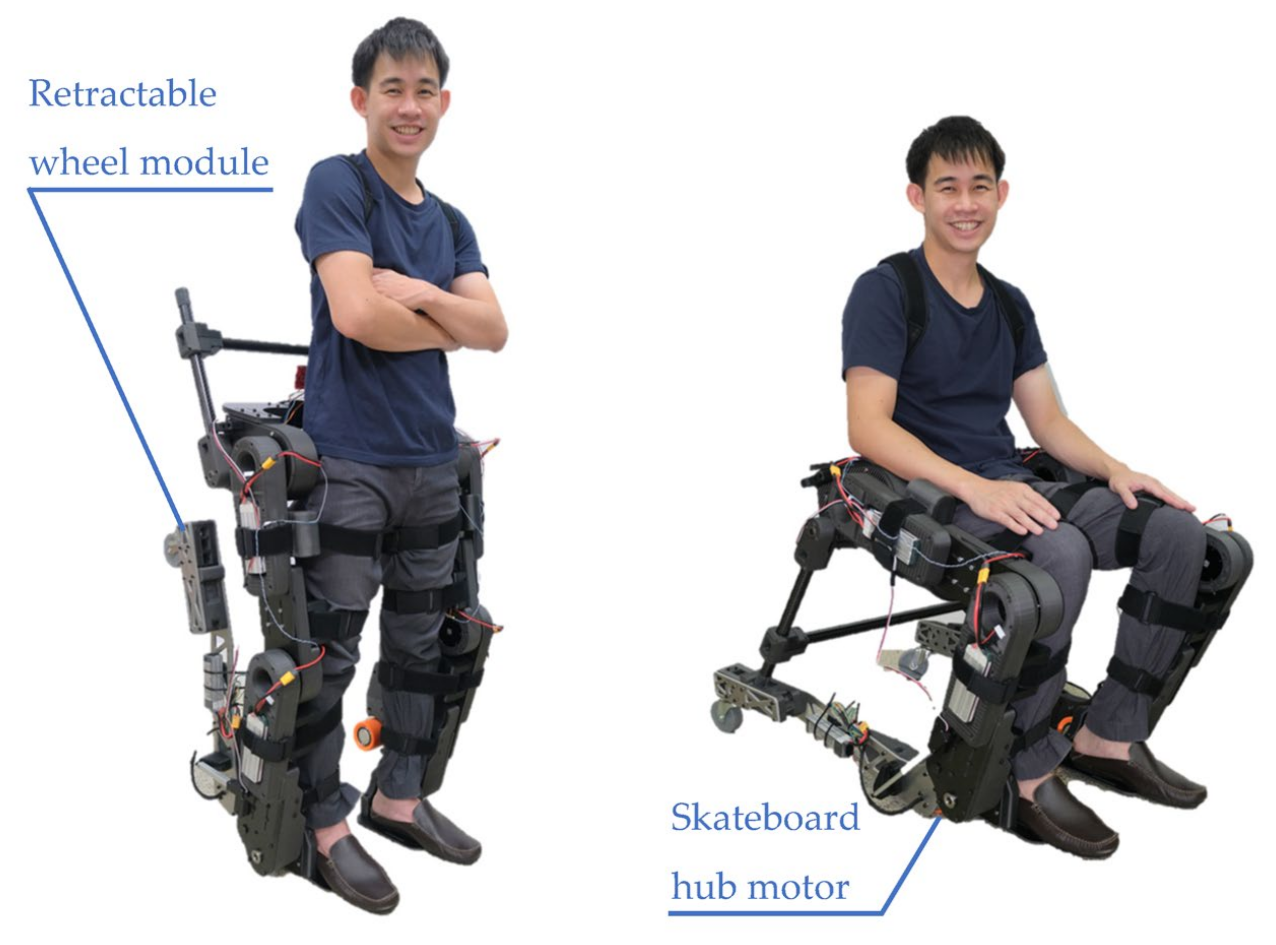
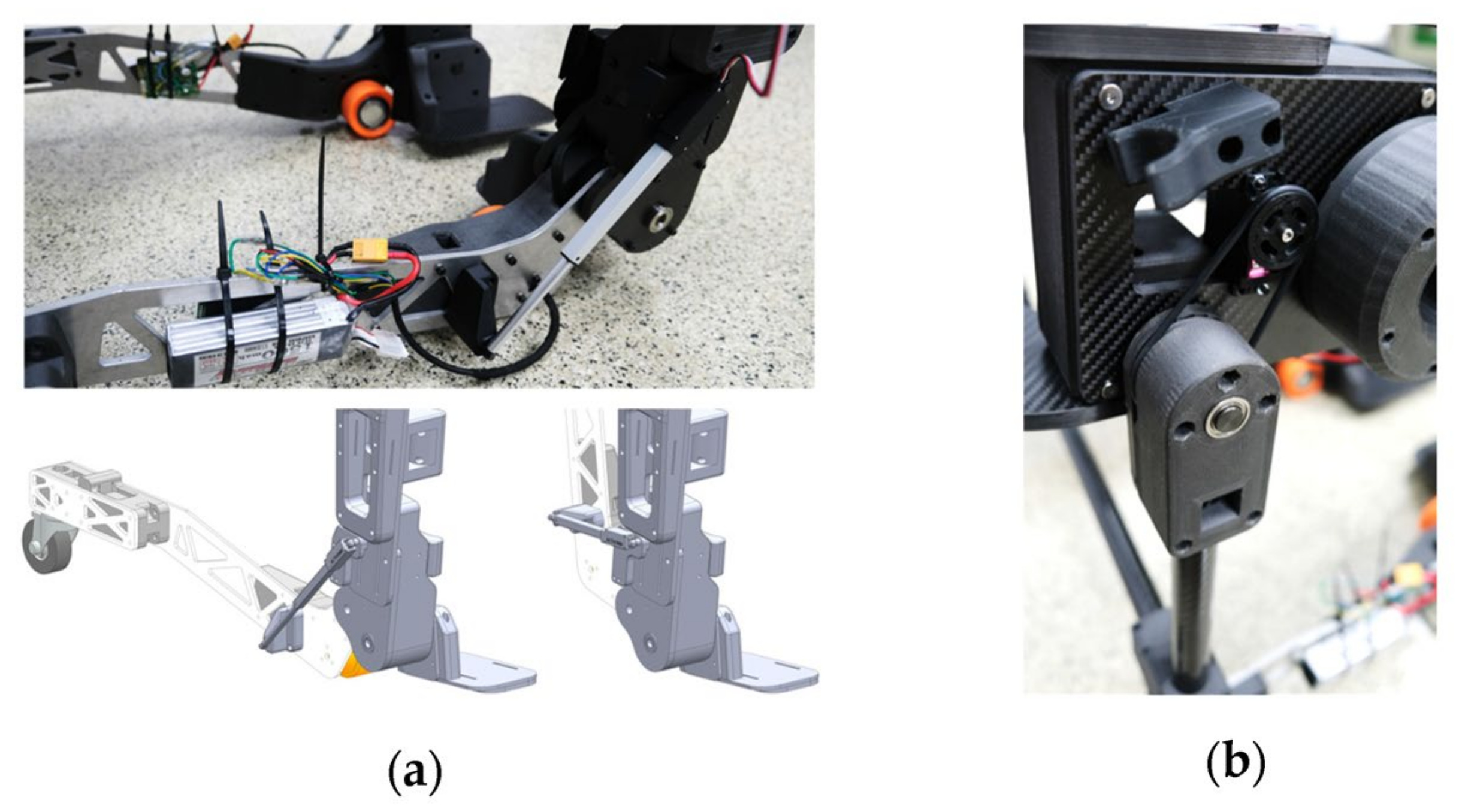
3.1. Experimental Prototype

The alpha prototype of the wheelchair–exoskeleton hybrid robot was built, as shown in Figure 3. The lower-limb exoskeleton uses planetary-geared motors to support the hip and knee joints, while the ankle joints are passive. The spring mechanism required to support the small rotation of the ankle will be designed in the future. For the hip joints, the T-Motor AK10-9 with a peak torque of 38 N·m and a weight of 820 g was used. For the knee joints, the T-Motor AK70-10 with a peak torque of 24.8 N·m and a weight of 521 g was used. The lower-back assembly connecting the left and right hip joints, thigh, shank, and foot assemblies were built from CNC-cut carbon fiber parts (8–12 mm thick) reinforced with 3D printed nylon (PA6-CF) parts. In the standing upright posture to prepare for walking or stepping over obstacles, the left and right wheel modules are retracted to the lower legs of the exoskeleton, as shown in Figure 4a, by using Actuonix L16-100-63-6-R linear actuators with the maximum pulling force of 100 N and the stroke length of 100 mm (~5 s is required for full-stroke traveling). The foldable chair legs made from carbon fiber tubes (25 mm diameter) are pinned to the lower-back assembly posterior to the hip joints and driven by two servo motors assembled on both sides via elastomer cords, as illustrated in Figure 4b. For safe travel in wheelchair mode on smooth surfaces with low energy consumption, the left and right wheel modules pinned to the lower legs of the exoskeleton are driven by the 7065 skateboard hub motors located as the front wheels. Meanwhile, the 75 mm casters are used as the rear wheels to allow turning with the differential driving technique. The total mass of the exoskeleton prototype is 20.2 kg, and the maximum width is 67.4 cm.

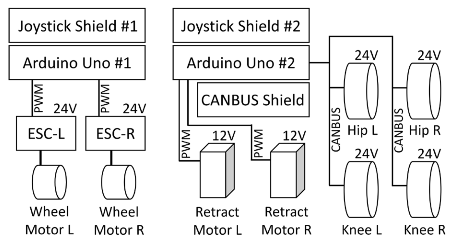
3.2. Control System Integration

The schematic in Figure 5 shows the control system implemented in the wheelchair–exoskeleton hybrid robot prototype. For the operation of the robot in wheelchair mode, the first microcontroller is programmed to receive commands from the user via a two-channel analog joystick. The desired maneuvers (i.e., forward, backward, right turn, and left turn) are achieved by controlling the speeds of the two skateboard hub motors by using the electronic speed control circuits via pulse-width modulation (PWM). The second microcontroller also sends PWM signals to control the position of the linear actuators retracting the left and right wheel modules. For supporting sit-to-stand and stand-to-sit motions in exoskeleton mode, the microcontroller receives the user’s commands via the second analog joystick. The CANBUS shield is used for communication with the motors driving the exoskeleton’s hip and knee joints. The T-Motor’s integrated controller computes the reference torque τ r e f via the equation:
τ r e f = k p θ d θ + k d θ ˙ d θ ˙ + τ f f ,
in accordance with the feedforward torque τ f f , the torsional stiffness k p , the damping coefficient k d , the equilibrium position θ d , and the reference joint velocity θ ˙ d . Once the command package is sent to the motor, the feedback data consisting of the current position θ , joint velocity θ ˙ , and torque are returned to the microcontroller.
The positive command received from the second joystick is related to the assistive levels for supporting the knee and hip extension moments during sit-to-stand motion. The reference joint velocities are commanded by the user while the damping coefficients of the motors are set. The negative command from the joystick is used to support the stand-to-sit motion. The equilibrium position of each joint is set to correspond to the standing posture. Meanwhile, torsional stiffness is adjusted on the basis of assistive levels.

4. Sit-to-Stand and Stand-to-Sit Experiment

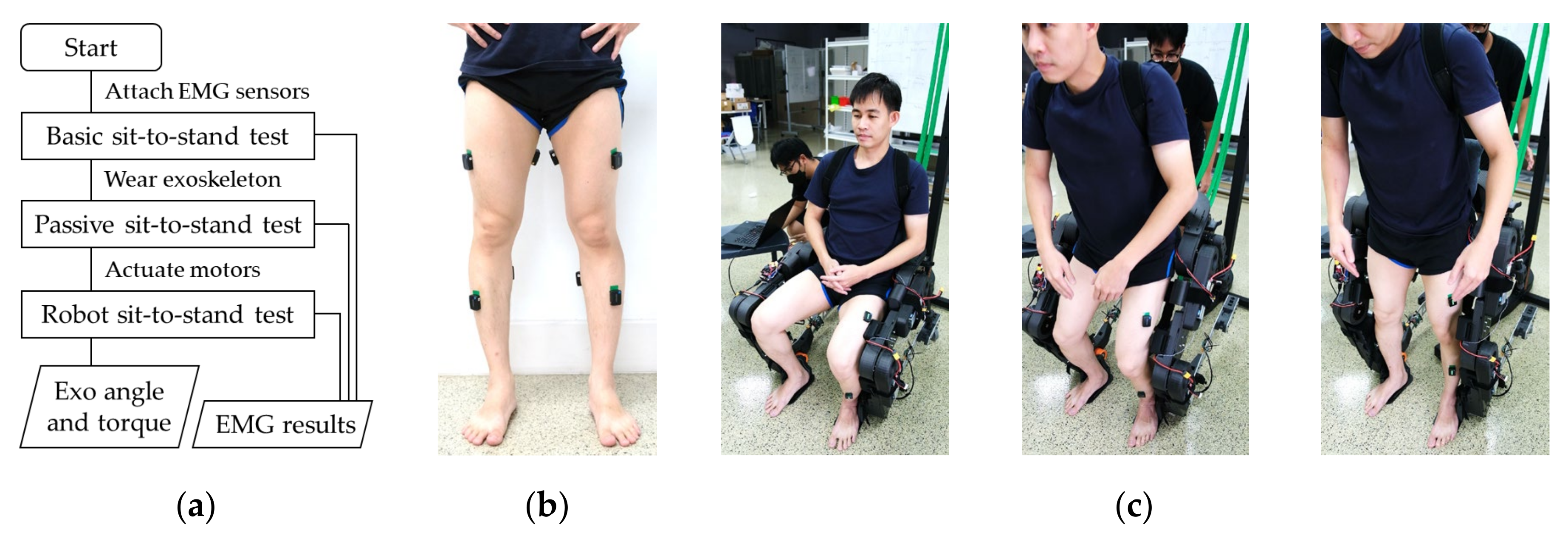
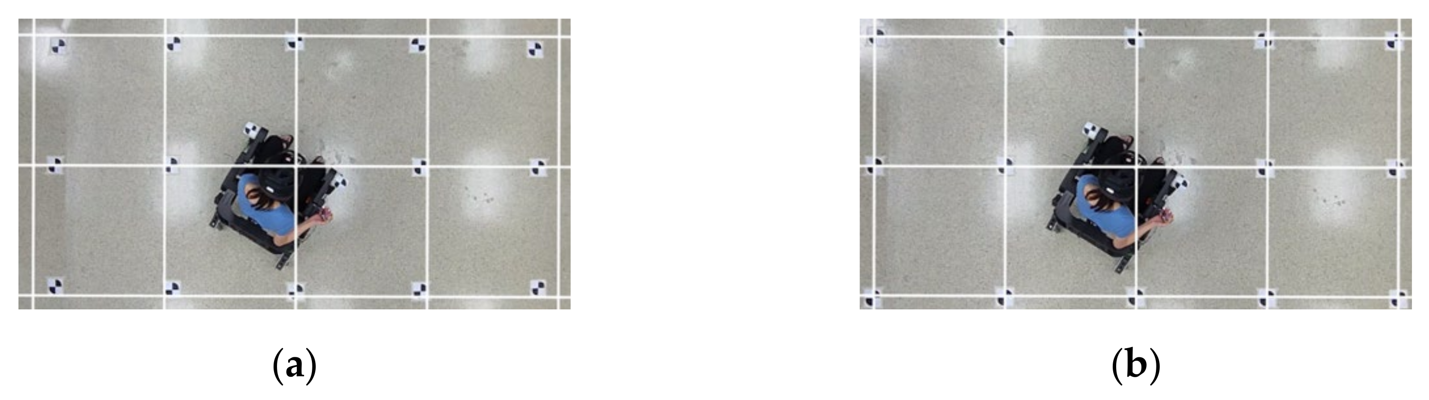
4.1. Experimental Setup and Procedure

An experiment was conducted, as seen in the flowchart shown in Figure 6a, on a healthy male participant with a height of 172 cm and weight of 65 kg to evaluate the assistive performance of the exoskeleton prototype in supporting sit-to-stand and stand-to-sit motions. For the observation of muscle activities, DELSYS’s wireless EMG sensor (Trigno™) electrodes were attached to both legs, as shown in Figure 6b. The electrodes covered the vastus lateralis (VL), the bicep femoris (BF), the tibialis anterior (TA), and the gastrocnemius (GC) muscles. The EMG signals were processed using the sliding root mean square filter with a window length of 0.125 s and a window overlap of 0.0625 s. The current position and the torque of the exoskeleton’s knee and hip motors were also recorded at the sampling frequency of 5 Hz.
The sit-to-stand and stand-to-sit experiments were conducted three times. The participant performed the test without wearing the exoskeleton (basic sit-to-stand test) to obtain reference results. For the observation of the effect of the inertia, damping, and friction on the human by the robot’s structure, the participant wore the exoskeleton, as shown in Figure 6c, and performed motions without actuating the motors (passive sit-to-stand test). The motors were actuated to provide knee extension support during sit-to-stand and stand-to-sit motions (robot sit-to-stand test) to evaluate the assistive performance of the exoskeleton.

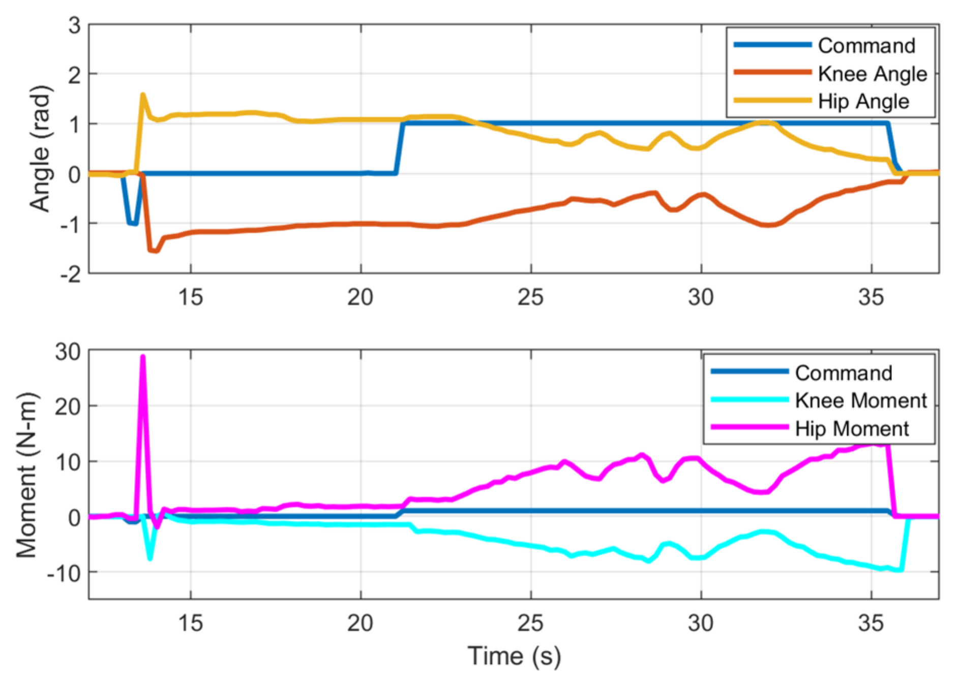
4.2. Recorded Position and Torque of the Exoskeleton Motors

The results in Figure 7 show the angle and moment recorded from the knee and hip motors of the exoskeleton’s right leg during the experiment. In the blue plot, command −1 (at 13.2 s) indicates the user’s intention of receiving the knee and hip extension moments supporting the sit-to-stand motion. The knee angle (orange plot) decreases from 0 rad to −1.54 rad (the motor rotates CCW) in less than 1 s. Simultaneously, the hip angle (yellow plot) increases from 0 rad to 1.54 rad (the motor rotates CW). In consideration of the moments, the peak torque magnitude of the knee motor (cyan plot) reaches 7.5 N·m, whereas that of the hip motor (magenta plot) reaches 29 N·m. After standing upright, the command 0 (at 13.6 s) is sent by the user. The stiffness of the knee and hip joints are set such that the motors behave as torsion springs with the equilibrium positions corresponding to the standing posture. The motor stiffness is sufficient to compensate for the weight of the exoskeleton’s structure. The magnitude of torque when command 0 is sent (from 13.6 to 21.2 s) is related to each motor’s displacement from its equilibrium. The command signal +1 is sent (from 21.4 s) to evaluate the assistive performance with the virtual spring concept. While maintaining the equilibriums of the motors at the standing upright posture, the higher stiffness is now set to the motors, as can be observed on the basis of the higher torque-to-displacement ratios during the three cycles of squatting. During stand-to-sit motion (from 32.0 s), the magnitudes of the knee and hip angles converge to the original angles before standing, whereas those of the torque increase with the motors’ displacement measured from their equilibriums in the standing posture.

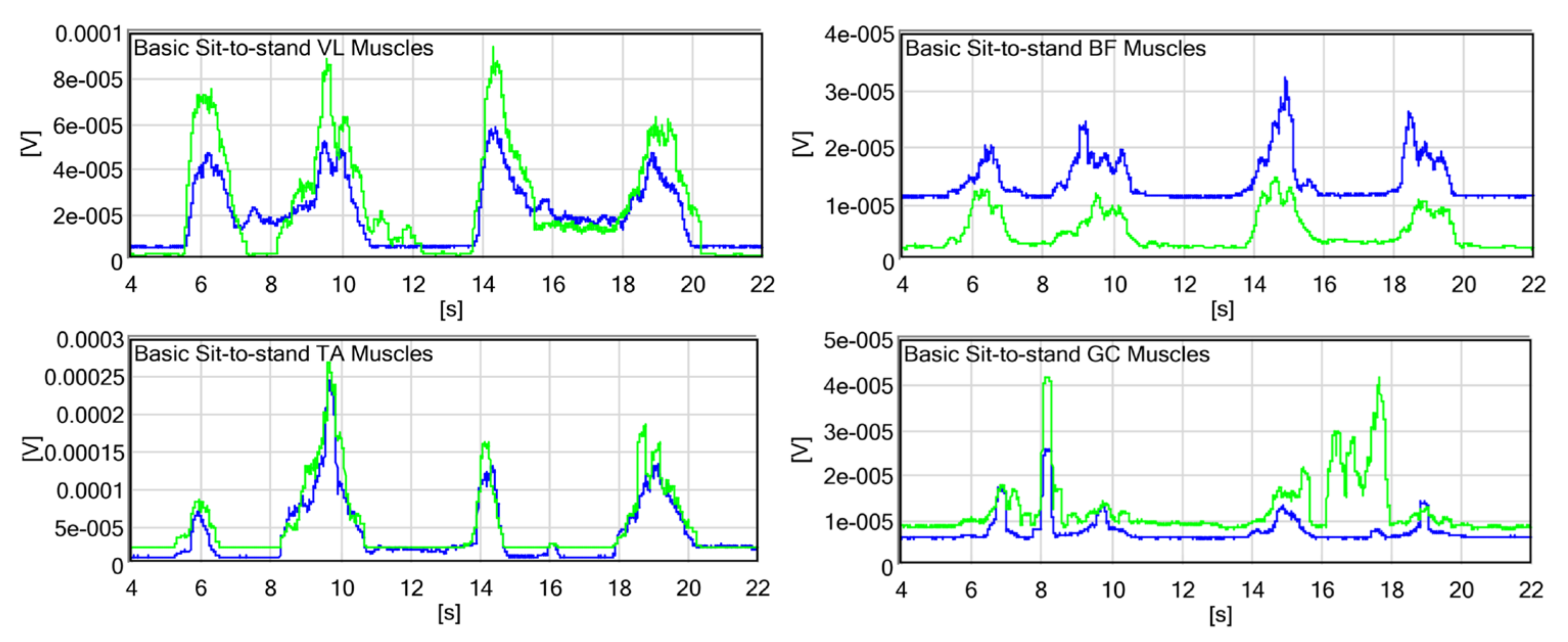
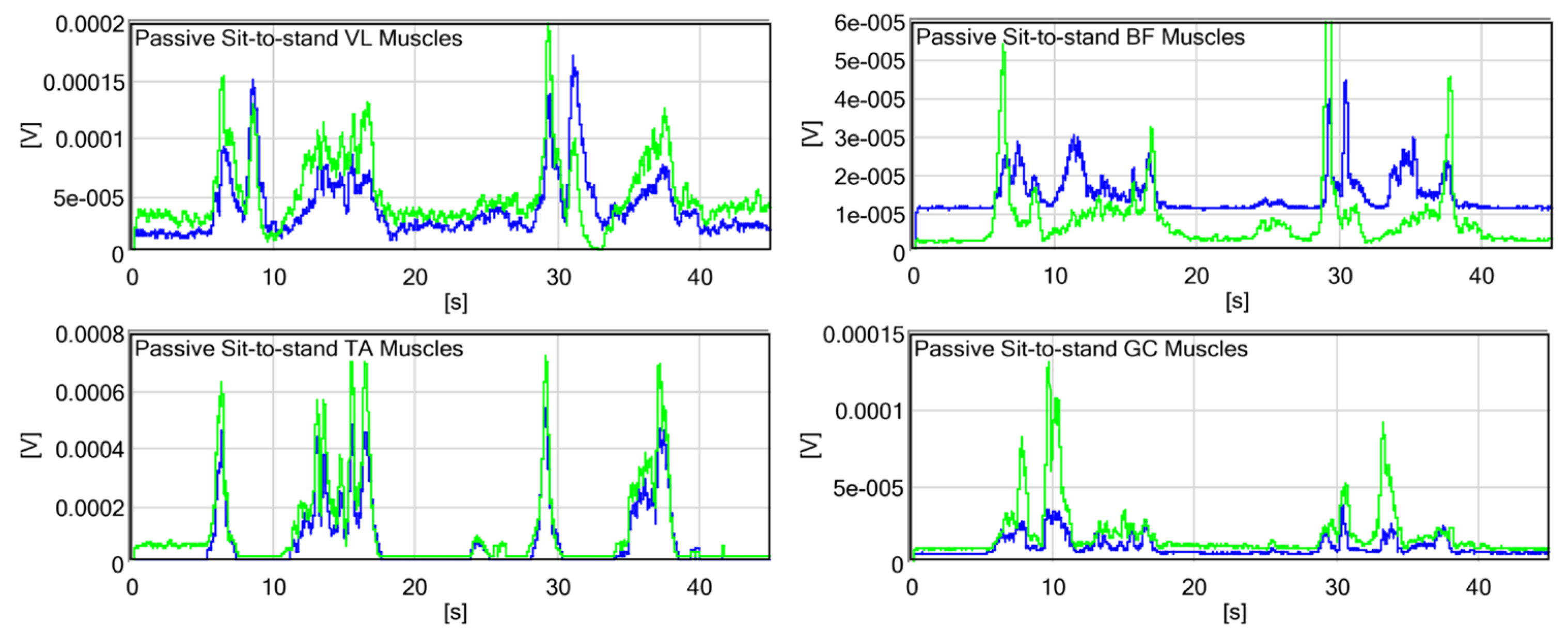
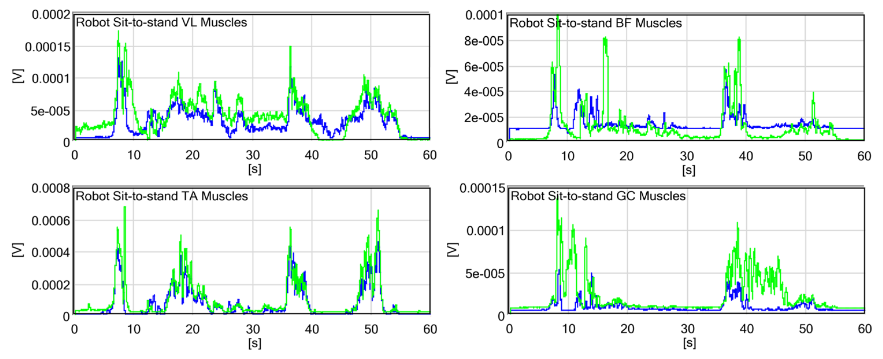
4.3. Leg Muscle Activity Observed via Surface EMG

The EMG results shown in Figure 8 were recorded during the two cycles of the basic sit-to-stand test without the exoskeleton. The activity of the VL muscle (quadriceps), supporting the knee extension moment, was observed during standing, maintaining an upright posture, and sitting. The peak values of standing and sitting are similar. The activity of the BF muscle (hamstrings) supporting hip extension is observed during standing and sitting and is almost zero without movement. The activity of the TA muscle supporting dorsiflexion (to move the body’s CG forward) occurs prior to that of the other muscles. The muscle is activated again to prevent falling backward during sitting down. The activity of the GC muscle supporting plantar flexion is observed in the latter phase of standing to balance the body in an upright posture and prevent falling forward. The EMG results shown in Figure 9 were recorded during the passive sit-to-stand test. The activity of the VL muscle, in this case, is similar to that in the absence of the exoskeleton. However, the second peak during standing is notable compared with the first peak (more effort is required to support the robot structure). A reduction in activity is observed while maintaining an upright posture. The activity of BF is further extended during sitting because the participant needs to confirm the stable sitting structure. Although the activities of TA and GC have higher peak values, the collaboration between both legs is more consistent when the exoskeleton is worn. The EMG results shown in Figure 10 were recorded during the robot sit-to-stand test. The activity of the VL muscle is reduced in the second peak of standing because the motors support knee extension.

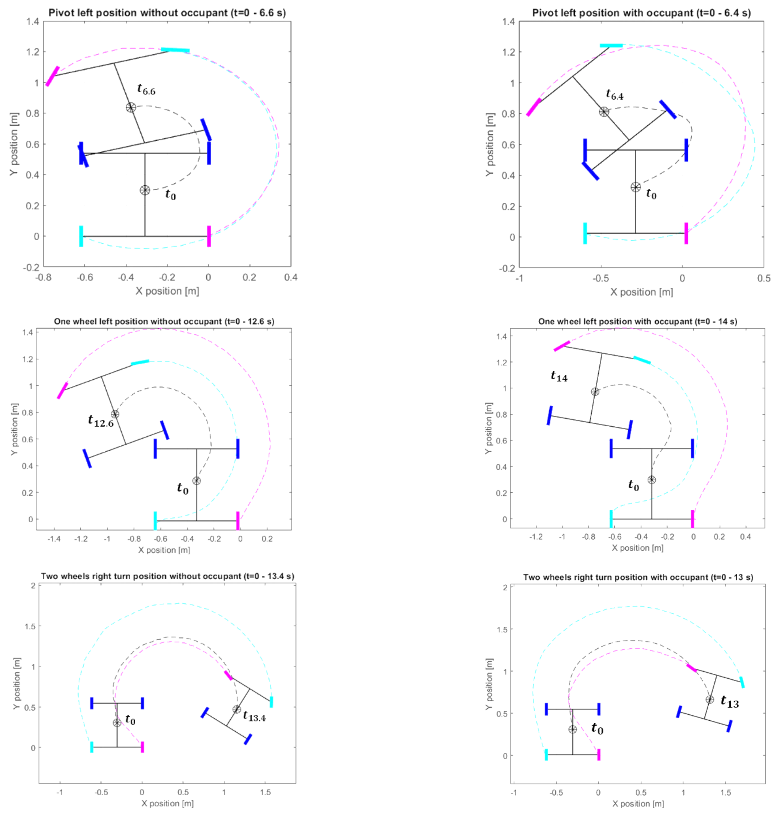
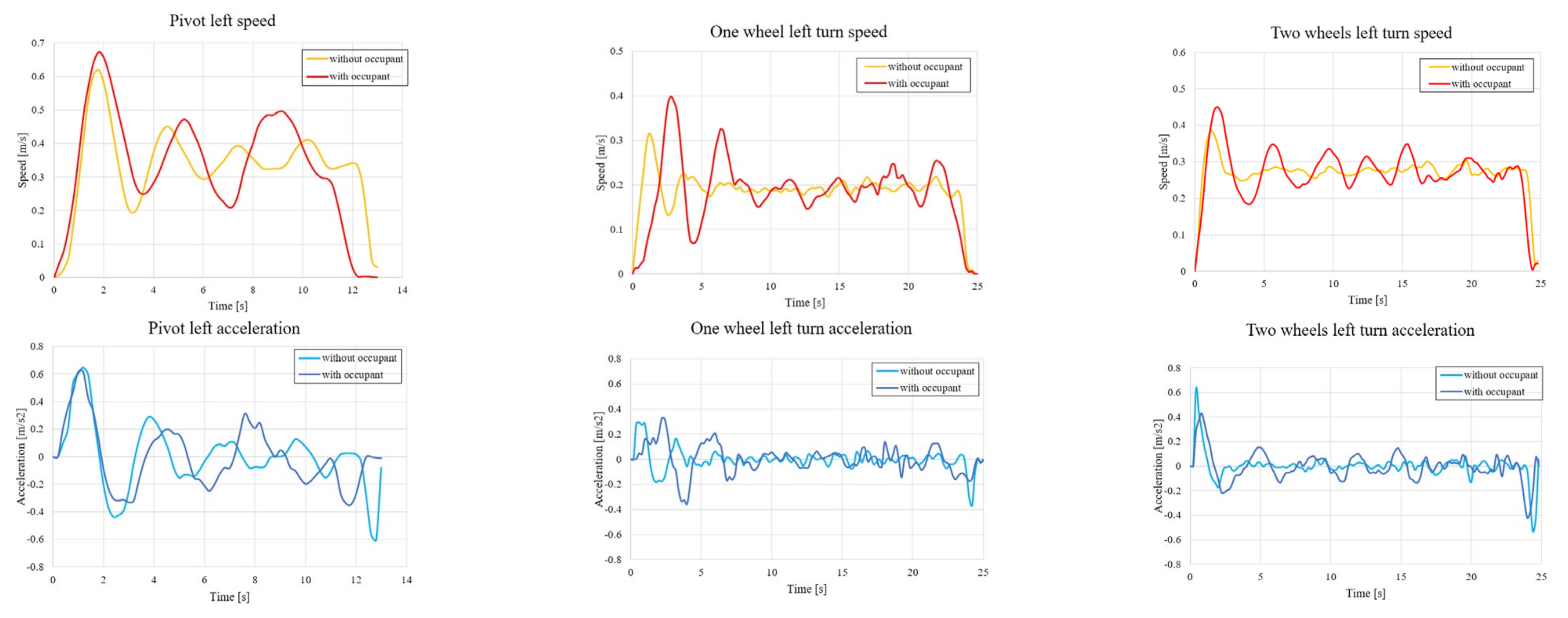
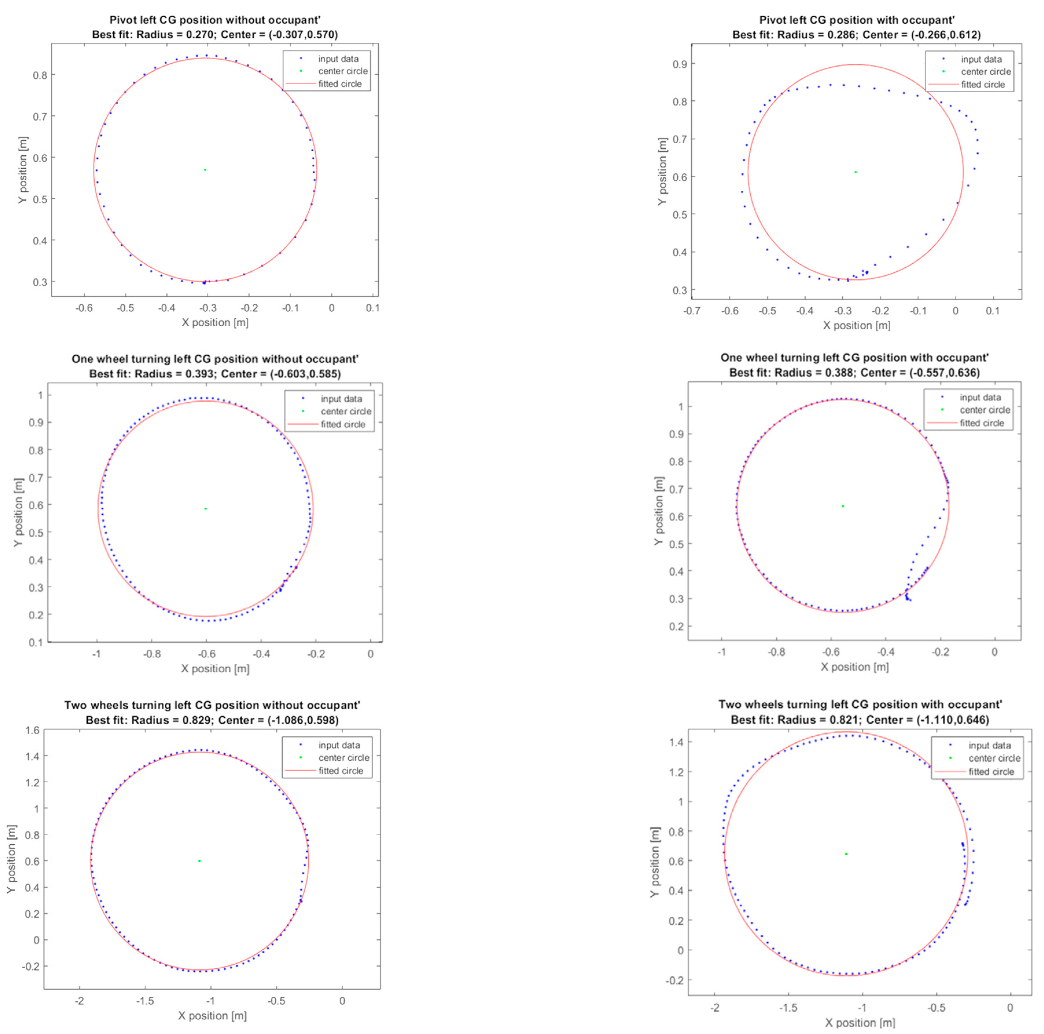
5. Differential Driving Experiment

Another primary focus of this research is the wheel module and its functionality in driving the exoskeleton. There are some scenarios that require steering or turning capability while traveling in the wheelchair mode rather than transforming to the exoskeleton mode before changing direction. The module is desired to pivot and turn with a minimal turning radius, as a human turns, without moving forward. The steering mechanism relies on the implementation of caster wheels in the rear and the two driving hub motors in the front. The difference between the speed of both wheels leads to turning from the front as the rear caster wheels move to accommodate the turn [33]. In theory, this situation means that minimal wheel slips [34] occur and that the wheelchair can turn without a complex steering mechanism.

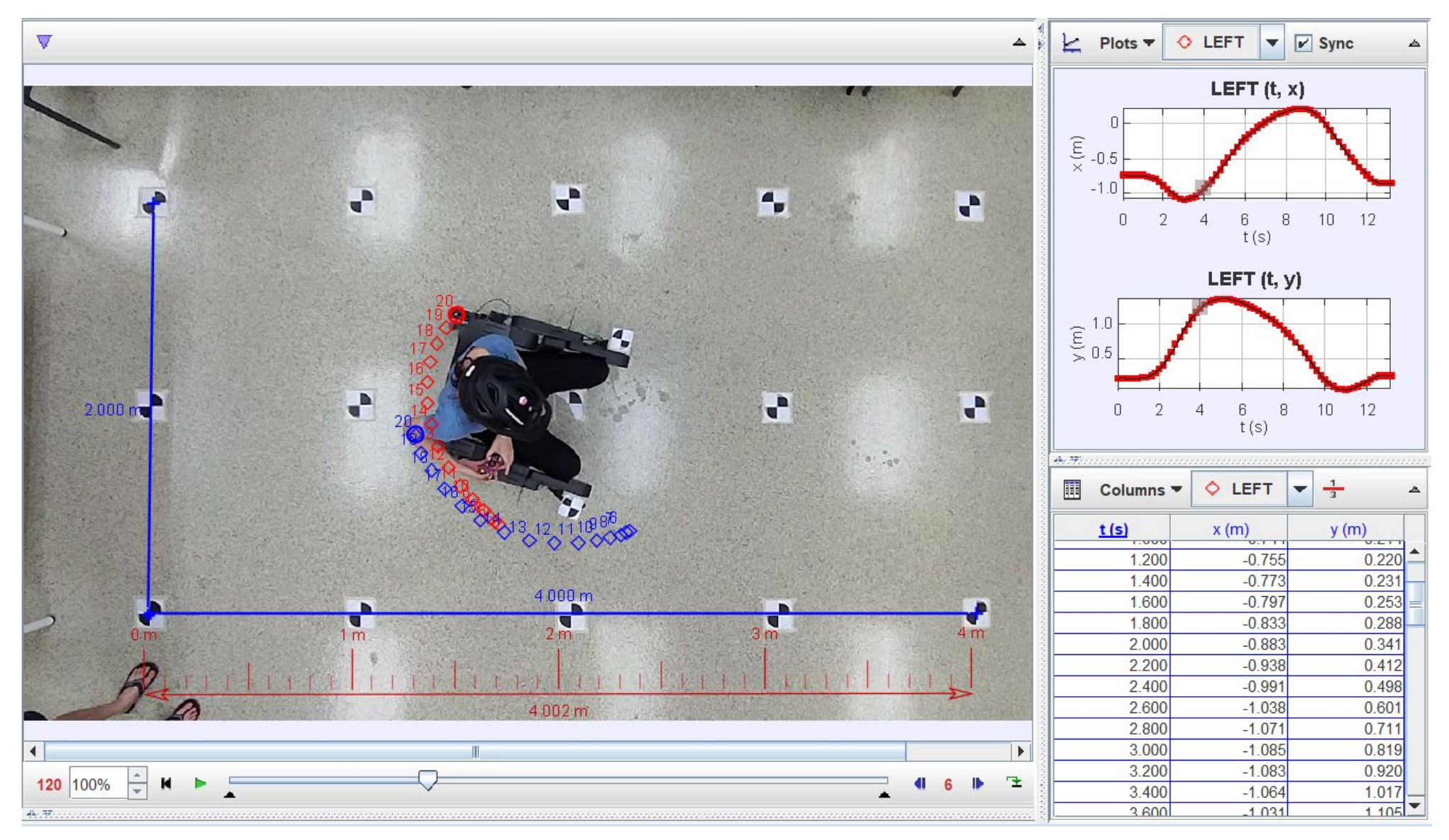
5.1. Experimental Setup and Procedure

The two skateboard hub motors are driven by the ODrive motor controller. Through the command prompt, the wheel speed and current limits are configured for safety. The calibration of the ODrive is recommended with the wheels over the ground because the low default current used for calibration is insufficient for creating high output torque. The percentage of throttle received from the user via the analog joystick is converted into the wheel speed of the motors. Preset movements, such as pivoting and turning for the increased consistency of control in certain situations, are also programmed in the microcontroller.
This experiment evaluated three scenarios, which were repeated for turning left and right: pivoting, turning with one wheel, and turning with both wheels. All driving cases were programmed and mapped to command buttons for the convenient repeatability of consistent motor output. “Pivoting” is defined as one wheel spinning forward as the other spins in the opposite direction to induce a rotation about the vertical axis at the midpoint between both driving wheels. “Turning with one wheel” is defined as spinning only one wheel to induce rotation about the other wheel, which is locked to not spin. “Turning with both wheels” is defined as allowing both wheels to spin at different speeds to induce the rotation of the wheelchair due to the difference in wheel speeds. The wheel speed used in the pivoting and the one-wheel turning cases is 0.5 round/s. The wheel speeds used in the case wherein both wheels turn are 1.0 and 0.5 round/s.
A top-down imaging setup is required to record the position and orientation of the wheelchair under various conditions to determine the radius of curvature when the wheel modules are turning. This setup is established by using a wide-lens phone camera mounted at a fixed height from the floor and linked to a laptop via TeamViewer. Figure 11 shows that the markers are attached to the floor in a 5 × 3 array, all within the frame and evenly spaced out by 1 m for calibration and postprocessing. Another two moving markers are attached to the wheelchair. Given the distortion of the wide lens, the calibration footage of checkered images must be taken to rectify the images. OpenCV is used to rectify the image by setting the camera distortion offset value. Then, by using the Tracker program built on the Open Source Physics Java framework, dimension measurement is done on each reference point to obtain the 4 × 2 m reference grid. This result is then verified by using a length calibration video wherein the wheelchair is pushed around within the frame. Considering that the markers on the wheelchair are a known value, the values obtained from the program can be acquired with this value to confirm the accuracy of the Tracker program.
The pivoting and one-wheel turning cases are conducted at the center reference point for ease of observation, whereas the case wherein both wheels turn is conducted with an offset from the center reference to accommodate the larger radius of curvature. The video recordings are processed via OpenCV to eliminate distortion from wide lines. Figure 12 illustrates that the Tracker is used to track the wheelchair as it turns in each case. Sample points are taken at both caster wheels once every six frames (or 0.2 s per point, given that the video is 30 frames per s).

5.2. Experimental Results

Figure 13 shows that the CG position and orientation of the wheelchair are computed from the time-varying coordinates of both caster wheels via kinematic relationships as adapted from a previous study [35]. The left and right wheel modules can enable turning, given the layout of the design. For all the turning strategies, the arc trajectories of the wheelchair–human’s CG, left, and right caster wheels are observed to be smoother without the occupant. The midpoint between the front driving wheels is slightly shifted behind during pivoting. In consideration of the slope at the time t 0 of the left caster’s arc trajectory (cyan) during turning with one wheel, the delay of caster steering is notable with the occupant. The position shift is also observed on the locked (front left) wheel. The CG trajectory lies between the left and the right caster wheels’ trajectories during turning with both wheels.
The magnitudes of the CG’s velocity and acceleration are estimated and plotted in Figure 14. As a result of the PID control, the damped vibration response to the step reference can be observed in the velocity plots. In all scenarios, the settling times appear to be smaller without the occupant. The lower inertia system (without the passenger mass) is advantageous when the limited control input (driving torque of the hub motors) is considered. The effect of the occupant on the response delay is notable during turning with one wheel, which corresponds to the delay in caster steering. The lower percentages of the maximum overshoot are observed during turning with both wheels.
The Taubin algebraic method is applied to the CG trajectories to determine the best-fit circles representing the turning radius of the wheelchair for each case, as shown in Figure 15. As expected, pivoting provides the smallest radius of curvature because the axis of rotation (the midpoint between the two front driving wheels) is close to the CG position. The CG trajectory is not a smooth circle with the occupant, especially when the radius of curvature is small. Except for that, in the pivoting case, the existence of the passenger slightly reduces the radius.

6. Conclusions and Future Work

This paper presents a design concept of a wheelchair–exoskeleton hybrid robot that can transform between sitting and standing configurations as a possible alternative for assisting the elderly or people with disabilities. The wheelchair mode allows traveling on smooth surfaces at high speeds with increased safety and reduced energy consumption. The compact wheel modules using skateboard hub motors can be retracted to prepare for walking. Given that the back-drivability of the exoskeleton joints is the primary concern for a safe physical human–robot interaction, the wheelchair parameters are designed on the basis of the simplified human model such that the actuators’ torque limitation is still sufficient to support the sit-to-stand motion. The wheelchair–exoskeleton hybrid robot prototype was built and tested on a healthy male volunteer to investigate the characteristics of the device for further improvement.
During sit-to-stand and stand-to-sit motions, the wearer must bend their trunk forward adequately to locate the body’s CG anterior to the front wheels to prevent falling backward. For users who are able to operate their upper limbs, crutches might be a possible solution to reduce the requirement of bending the body forward. For improving the design, shifting the pivot position behind is beneficial in terms of standing stability. The parallel elastic concepts [36,37,38] can be applied to safely enhance the torque capacity of the exoskeleton joints. A motion controller should be developed for walking and stair climbing [39,40]. Analytical and experimental studies on the integral of power consumption over time for the wheelchair and the exoskeleton modes will be considered. For evaluating the exoskeleton performance at different assistive levels, the quantitative analysis of EMG collected from experiments conducted under the controlled condition with appropriate measurement of body kinematics is required. The velocity profile and desired radius of curvature can be mapped on the basis of the results of the differential driving experiment.

Author Contributions

Conceptualization, R.C.; methodology, R.C., S.P. and S.T.; software, R.C. and S.P.; validation, R.C., S.P. and S.T.; formal analysis, R.C. and S.P.; investigation, R.C., S.P. and S.T.; resources, R.C.; data curation, R.C., S.P. and S.T.; writing—original draft preparation, R.C., S.P. and S.T.; writing—review and editing, R.C.; visualization, R.C., S.P. and S.T.; supervision, R.C.; project administration, R.C.; funding acquisition, R.C. All authors have read and agreed to the published version of the manuscript.

Funding

This research was partially funded by Thailand Science Research and Innovation Fund, Chulalongkorn University (CU_FRB65_ind (14)_162_21_28), and by the National Research Council of Thailand.

Data Availability Statement

The data presented in this study are available on request from the corresponding author. The data are not publicly available due to privacy.

Conflicts of Interest

The authors declare no conflict of interest.

References

  1. Sarraj, A.R.; Massarelli, R. Design history and advantages of a new lever-propelled wheelchair prototype. Int. J. Adv. Robot Syst. 2011, 8, 12–21. [Google Scholar] [CrossRef]
  2. Sasaki, K.; Eguchi, Y.; Suzuki, K. Step-climbing wheelchair with lever propelled rotary legs. In Proceedings of the 2015 IEEE/RSJ International Conference on Intelligent Robots and Systems, Hamburg, Germany, 28 September–3 October 2015; pp. 6354–6359. [Google Scholar]
  3. Lawn, M.J.; Ishimatsu, T. Modeling of a stair-climbing wheelchair mechanism with high single step capability. IEEE Trans. Neural Syst. Rehabil. Eng. 2003, 11, 323–332. [Google Scholar] [CrossRef] [PubMed] [Green Version]
  4. Chatterjee, P.; Lahiri, N.; Bhattacharjee, A.; Chakraborty, A. Automated hybrid stair climber for physically challenged people. In Proceedings of the International Conference on Electronics, Materials Engineering & Nano-Technology, Kolkata, India, 24–26 September 2021; pp. 1–4. [Google Scholar]
  5. Suryanto, M.F.I.; Badriawan, N.A.; Ningrum, E.S.; Binugroho, E.H.; Satria, N.F. Balance control on the development of electric wheelchair prototype with standing and stair climbing ability with tracked-wheel mechanism. In Proceedings of the 2018 International Electronics Symposium on Engineering Technology and Applications, Bali, Indonesia, 29–30 October 2018; pp. 43–47. [Google Scholar]
  6. Munton, J.S.; Ellis, M.I.; Chamberlain, M.A.; Wright, V. An investigation into the problems of easy chairs used by the arthritic and the elderly. Rheum. Rehabil. 1981, 20, 164–173. [Google Scholar] [CrossRef] [PubMed]
  7. Mano, Y.; Sakakibara, T.; Takayanagi, T. Kinesiological analysis of standing-up movement. Excerpta Med. Int Congr. Ser. 1988, 804, 503–512. [Google Scholar]
  8. Levo: Products. Available online: https://www.levo.ch/products (accessed on 11 December 2022).
  9. Superior ME. Available online: http://Superiorstanding.mamutweb.com/subdet1.htm (accessed on 11 December 2022).
  10. Eguchi, Y.; Kadone, H.; Suzuki, K. Standing mobility device with passive lower limb exoskeleton for upright locomotion. IEEE ASME Trans. Mechatron. 2018, 23, 1608–1618. [Google Scholar] [CrossRef]
  11. Hayashi, T.; Kawamoto, H.; Sankai, Y. Control method of robot suit HAL working as operator’s muscle using biological and dynamical information. In Proceedings of the 2005 IEEE/RSJ International Conference Intelligent Robots and Systems, Edmonton, AB, Canada, 2–6 August 2005; pp. 3063–3068. [Google Scholar]
  12. Mertz, L. The next generation of exoskeletons: Lighter, cheaper devices are in the works. IEEE Pulse 2012, 3, 56–61. [Google Scholar] [CrossRef] [PubMed]
  13. Zeilig, G.; Weingarden, H.; Zwecker, M.; Dudkiewicz, I.; Bloch, A.; Esquenazi, A. Safety and tolerance of the ReWalk™ exoskeleton suit for ambulation by people with complete spinal cord injury: A pilot study. J. Spinal Cord Med. 2012, 35, 96–101. [Google Scholar] [CrossRef] [Green Version]
  14. Barbareschi, G.; Richards, R.; Thornton, M.; Carlson, T.; Holloway, C. Statically vs dynamically balanced gait: Analysis of a robotic exoskeleton compared with a human. In Proceedings of the 2015 IEEE/EMBS Annual International Conference, Milan, Italy, 25–29 August 2015; pp. 6728–6731. [Google Scholar]
  15. Duddy, D.; Doherty, R.; Connolly, J.; McNally, S.; Loughrey, J.; Faulkner, M. The effects of powered exoskeleton gait training on cardiovascular function and gait performance: A systematic review. Sensors 2021, 21, 3207. [Google Scholar] [CrossRef]
  16. Borisoff, J.F.; Mattie, J.; Rafer, V. Concept proposal for a detachable exoskeleton-wheelchair to improve mobility and health. In Proceedings of the 2013 IEEE International Conference on Rehabilitation Robotics, Seattle, WA, USA, 24–26 June 2013. [Google Scholar]
  17. Shankar, T.; Dwivedy, S.K. A hybrid assistive wheelchair-exoskeleton. In Proceedings of the 2015 International Convention on Rehabilitation Engineering and Assistive Technology, Singapore, 5–7 November 2015. [Google Scholar]
  18. Song, Z.; Tian, C.; Dai, J.S. Mechanism design and analysis of a proposed wheelchair-exoskeleton hybrid robot for assisting human movement. Mech. Sci. 2019, 10, 11–24. [Google Scholar] [CrossRef] [Green Version]
  19. Chaichaowarat, R.; Nishimura, S.; Krebs, H.I. Macro-mini linear actuator using electrorheological-fluid brake for impedance modulation in physical human–robot interaction. IEEE Robot Autom. Lett. 2022, 7, 2945–2952. [Google Scholar] [CrossRef]
  20. Chaichaowarat, R.; Nishimura, S.; Krebs, H.I. Design and modeling of a variable-stiffness spring mechanism for impedance modulation in physical human–robot interaction. In Proceedings of the 2021 IEEE International Conference on Robotics and Automation, Xi’an, China, 30 May–5 June 2021; pp. 7052–7057. [Google Scholar]
  21. Millington, P.J.; Myklebust, B.M.; Shambes, G.M. Biomechanical analysis of the sit-to-stand motion in elderly persons. Arch. Phys. Med. Rehabil. 1992, 73, 609–617. [Google Scholar] [PubMed]
  22. Chorin, F.; Cornu, C.; Beaune, B.; Frere, J.; Rahmani, A. Sit to stand in elderly fallers vs non-fallers: New insights from force platform and electromyography data. Aging Clin. Exp. Res. 2016, 28, 871–879. [Google Scholar] [CrossRef]
  23. Pal, A.R.; Pratihar, D.K. Estimation of joint torque and power consumption during sit-to-stand motion of human-being using a genetic algorithm. Procodia Comp. Sci. 2016, 96, 1497–1506. [Google Scholar] [CrossRef] [Green Version]
  24. Glowinski, S.; Ptak, M. A kinematic model of a humanoid lower limb exoskeleton with pneumatic actuators. Acta Bioeng. Biomech. 2022, 24, 145–157. [Google Scholar] [CrossRef]
  25. Huo, W.; Mohammed, S.; Amirat, Y.; Kong, K. Active impedance control of a lower limb exoskeleton to assist sit-to-stand movement. In Proceedings of the 2016 IEEE/RSJ International Conference on Intelligent Robots and Systems, Daejeon, Republic of Korea, 9–14 October 2016; pp. 3530–3536. [Google Scholar]
  26. Tsukahara, A.; Kawanishi, R.; Hasegawa, Y.; Sankai, Y. Sit-to-stand and stand-to-sit transfer support for complete paraplegic patients with robot suit HAL. Adv. Robot 2010, 24, 1615–1638. [Google Scholar] [CrossRef] [Green Version]
  27. Fattah, A.; Agrawal, S.K.; Catlin, G.; Hamnett, J. Design of a passive gravity-balanced assistive device for sit-to-stand tasks. J. Mech. Des. 2006, 128, 1122–1129. [Google Scholar] [CrossRef]
  28. Elibol, E.; Calderon, J.; Llofriu, M.; Moreno, W.; Weitzenfeld, A. Analyzing and reducing energy usage in a humanoid robot during standing up and sitting down tasks. Int. J. Hum. Robot 2016, 13, 1650014. [Google Scholar] [CrossRef]
  29. Kim, J.; Yang, J.; Yang, S.T.; Oh, Y.; Lee, G. Energy-efficient hip joint offsets in humanoid robot via Taguchi method and bioinspired analysis. Appl. Sci. 2020, 10, 7287. [Google Scholar] [CrossRef]
  30. Elibol, E.; Calderon, J.; Llofriu, M.; Quintero, C.; Moreno, W.; Weitzenfeld, A. Power usage reduction of humanoid standing process using Q-learning. In RoboCup 2015: Robot World Cup XIX, Lecture Notes in Computer Science; Almeida, L., Ji, J., Steinbauer, G., Luke, S., Eds.; Springer: Cham, Switzerland, 2015; 9513; pp. 251–263. [Google Scholar]
  31. De Leva, P. Adjustments to Zatsiorsky–Seluyanov’s segment inertia parameters. J. Biomech. 1996, 29, 1223–1230. [Google Scholar] [CrossRef] [PubMed]
  32. Chaichaowarat, R.; Granados, D.F.P.; Kinugawa, J.; Kosuge, K. Passive knee exoskeleton using torsion spring for cycling assistance. In Proceedings of the 2017 IEEE/RSJ International Conference on Intelligent Robots and Systems, Vancouver, BC, Canada, 24–28 September 2017; pp. 3069–3074. [Google Scholar]
  33. Chaichaowarat, R.; Wannasuphoprasit, W. Full-slip kinematics based estimation of vehicle yaw rate from differential wheel speeds. KSAE Int. J. Automot. Tech. 2016, 17, 81–88. [Google Scholar] [CrossRef]
  34. Chaichaowarat, R.; Wannasuphoprasit, W. Kinematics-based analytical solution for wheel slip angle estimation of a RWD vehicle with drift. Eng. J. 2016, 20, 89–107. [Google Scholar] [CrossRef]
  35. Chaichaowarat, R.; Wannasuphoprasit, W. Wheel slip angle estimation of a planar mobile platform. In Proceedings of the 1st International Symposium on Instrumentation, Control, Artificial Intelligence, and Robotics, Bangkok, Thailand, 16–18 January 2019; pp. 163–166. [Google Scholar]
  36. Chaichaowarat, R.; Kinugawa, J.; Kosuge, K. Unpowered knee exoskeleton reduces quadriceps activity during cycling. Engineering 2018, 4, 471–478. [Google Scholar] [CrossRef]
  37. Chaichaowarat, R.; Kinugawa, J.; Kosuge, K. Cycling enhance knee exoskeleton using planar spiral spring. In Proceedings of the 2018 IEEE/EMBS Annual International Conference, Honolulu, HI, USA, 18–21 July 2018; pp. 3206–3211. [Google Scholar]
  38. Chaichaowarat, R.; Kinugawa, J.; Seino, A.; Kosuge, K. A spring-embedded planetary-geared parallel elastic actuator. In Proceedings of the 2020 IEEE/ASME International Conference on Advanced Intelligent Mechatronics, Boston, MA, USA, 6–9 July 2020; pp. 952–959. [Google Scholar]
  39. Javadi, A.; Chaichaowarat, R. Position and stiffness control of an antagonistic variable stiffness actuator with input delay using super-twisting sliding mode control. Nonlinear Dyn. 2022, 1–23. [Google Scholar] [CrossRef]
  40. Chaichaowarat, R.; Macha, V.; Wannasuphoprasit, W. Passive knee exoskeleton using brake torque to assist stair ascent. In Proceedings of the 2020 IEEE Region 10 Conference, Osaka, Japan, 16–19 November 2020; pp. 1165–1170. [Google Scholar]
Figure 1. Conceptual design of the wheelchair–exoskeleton hybrid robot during the sit-to-stand transition on the sagittal plane. In the sitting configuration, the ground reaction force position is assumed to be at the front wheel. The trunk, head, and arms are simply considered a rigid upper-body link. The hip, knee, and ankle joint angles are shown. The weight of each segment is assumed to be at its center of gravity. The locations of the link lengths and center of gravity in the standing configuration are shown.
Robotics 12 00016 g001
Figure 2. Simulated sit-to-stand motion: (a) Simplified kinematics of sit-to-stand motion in our study. The ankle, knee, and hip joints shown by the red markers connect the shank, thigh, and body links. The links’ CGs are shown by the green makers. The origin of the plot is the intersection between the horizontal line crossing the ankle joint and the vertical line crossing the front wheel center; (b) Simulated knee and hip angles are plotted in blue and orange, respectively. The total duration of the sit-to-stand motion is approximately 2 min for this quasi-static simulation. The estimated knee and hip extension moments are plotted in blue and orange, respectively, and the total clockwise moment computed via Equation (6) is plotted in yellow.
Robotics 12 00016 g002
Figure 3. Alpha prototype of the wheelchair–exoskeleton hybrid robot in the standing upright posture (for walking across obstacles) and the wheelchair mode (for safe and low-energy traveling on smooth surfaces).
Robotics 12 00016 g003
Figure 4. (a) Wheel module’s retraction mechanism using the Actuonix linear actuator; (b) Foldable chair leg driven through the elastomer cord.
Robotics 12 00016 g004
Figure 5. Diagram of hardware integration. The first microcontroller with an analog joystick is used to control the robot running in wheelchair mode. The skateboard hub motors operated at 24 V are driven by the electronic speed control circuits receiving commands via pulse-width modulation (PWM) signals. The second microcontroller is used to control the exoskeleton’s hip and knee motors supporting sit-to-stand and stand-to-sit motions. The motors operated at 24 V receive the commands and return their status via CANBUS. The two linear actuators for retracting the left and right wheel modules are operated at 12 V and controlled via PWM signals.
Robotics 12 00016 g005
Figure 6. (a) Experimental setup and procedure; (b) Surface electromyography (EMG) electrodes (DELSYS’s Trigno™) were attached to both legs of the participant over the vastus lateralis (VL) in front of the thigh, the bicep femoris (BF) behind the thigh, the tibialis anterior (TA) in front of the shank, and the gastrocnemius (GC) behind the shank [32]; (c) The participant wearing the exoskeleton prototype performed sit-to-stand and stand-to-sit motions while recording the EMG of the muscles, along with the exoskeleton knee and hip motors’ position, velocity, and torque to evaluate assistive performance.
Robotics 12 00016 g006
Figure 7. Angle and moment of the exoskeleton’s right knee and hip motors.
Robotics 12 00016 g007
Figure 8. RMS electromyography (EMG) of the right (blue) and left (green) muscles recorded during the basic sit-to-stand test (without wearing the exoskeleton).
Robotics 12 00016 g008
Figure 9. RMS electromyography (EMG) of the right (blue) and left (green) muscles recorded during the passive sit-to-stand test (without actuation).
Robotics 12 00016 g009
Figure 10. RMS electromyography (EMG) of the right (blue) and the left (green) muscles recorded during the robot sit-to-stand test (with knee extension support).
Robotics 12 00016 g010
Figure 11. Markers are attached to the floor in a 5 × 3 array: (a) Original recording with distortion from wide lines; (b) Recording processed via OpenCV to yield the 4 × 2 m reference grid.
Robotics 12 00016 g011
Figure 12. Tracking of the coordinates of both caster wheels during turning.
Robotics 12 00016 g012
Figure 13. Examples of the wheelchair turning trajectories with/without the occupant during pivot left turns, one-wheel left turns, and two-wheel right turns. Blue markers indicate the front driving hub motors. Black, cyan, and pink markers and curves represent the wheelchair–human’s CG, left, and right caster wheels, respectively.
Robotics 12 00016 g013
Figure 14. Estimated CG velocity and acceleration with/without the occupant during pivot turns, one-wheel turns, and two-wheel turns.
Robotics 12 00016 g014
Figure 15. Best fit circles, based on the Taubin algebraic method, showing the turning radius of wheelchair with/without the occupant during pivot turns, one-wheel turns, and two-wheel turns.
Robotics 12 00016 g015
Table 1. Human model parameters applied from [31].
LinkMass (kg)Length (mm)CG Position (mm)
Thigh m t = 0.01 × (14.16 × 2) × M l t = 422.2 l t c = 0.01 × (40.95 × 422.2)
measured from hip joint
Shank m s = 0.01 × (4.33 × 2) × M l s = 434.0 l s c = 0.01 × (44.59 × 434.0)
measured from knee joint
Body-Head m b = 0.01 × (43.46 + 6.94) × M 603.3 + 242.9
from vertex to hip joint
l b c = [0.01/(43.46 + 6.94)] ×
[43.46 × (48.62 × 603.3) +
6.94 × (603.3 + 49.98 × 242.9)]
Disclaimer/Publisher’s Note: The statements, opinions and data contained in all publications are solely those of the individual author(s) and contributor(s) and not of MDPI and/or the editor(s). MDPI and/or the editor(s) disclaim responsibility for any injury to people or property resulting from any ideas, methods, instructions or products referred to in the content.

