
Dynamics of Twisted Electron Impact Ionization of CH4 and NH3 Molecule

Department of Physics, Birla Institute of Technology and Science-Pilani, Pilani Campus, Pilani 333031, Rajasthan, India
*
Author to whom correspondence should be addressed.
Atoms 2023, 11(5), 82; https://doi.org/10.3390/atoms11050082
Submission received: 3 March 2023
/
Revised: 6 May 2023
/
Accepted: 8 May 2023
/
Published: 10 May 2023
(This article belongs to the Special Issue Recent Advances in Atomic and Molecular Spectroscopy)
Abstract
:Electron vortex beams (EVBs, also known as twisted electron beams) possess an intrinsic orbital angular momentum (OAM) with respect to their propagation direction. This intrinsic OAM represents a new degree of freedom that provides new insights into investigating the dynamics of electron impact ionization. In this communication, we present, in the first Born approximation (FBA), the angular profiles of the triple differential cross section (TDCS) for the (e, 2e) process on CH and NH molecular targets in the coplanar asymmetric geometry. We compare the TDCS of the EVB for different values of OAM number m with that of the plane wave. For a more realistic scenario, we investigate the average TDCS for macroscopic targets to explore the influence of the opening angle of the twisted electron beam on the TDCS. In addition, we also present the TDCS for the coherent superposition of two EVBs. The results demonstrate that the twisted (e, 2e) process retrieves the p-type character of the molecular orbitals, which is absent in the plane wave TDCS for the given kinematics. The results for the coherent superposition of two Bessel beams show the sensitivity of TDCS toward the OAM number m.
1. Introduction
Studies on the potential applications of vortex beams (both optical and electron vortex beams) have increased over the past two decades, and thorough literature is available for both beams [1,2,3,4,5,6]. Electron vortex beams (EVBs, also termed as “twisted electron beams” or “Bessel beams”) represent experimentally realizable, freely propagating beams carrying a well-defined orbital angular momentum (OAM) about their propagation axis. Bliokh et al. [7] stimulated the current research activity in electron vortex beams and their OAM content. Subsequently, Uchida and Tonomura [8] and Verbeeck et al. [9] reported the generation of an EVB using a spiral phase plate and holographic technique in the transmission electron microscope, respectively. With the current experimental techniques, researchers have developed EVBs, having OAM up to 1000ℏ [10,11]. Examples such as energy-loss spectroscopy (EELS), the detection of the chirality of crystals [12,13], the manipulation of nanoparticles [14], the use of the inherent phase structure of EVB to image biological samples [15], and scattering studies [16,17,18] show the potential applications of the EVBs. To fully understand their applications, it is crucial to comprehend how the twisted electron beams interact with matter.
Electron-impact single ionization ((e, 2e) process) is one of the most fundamental processes in collision physics. In a coincident (e, 2e) process, an incident electron of definite energy ejects one of the bound electrons from the target upon interaction with the target, thus ionizing the target, and the outgoing electrons are detected with their energies and angles fully resolved. The triple-differential cross section (TDCSs) fully explains the ionization dynamics of a coincident (e, 2e) process. The (e, 2e) process on atomic and molecular targets has practical applications in fields such as plasma physics, astronomy, atmospheric physics, radiation physics, and biology, to name a few [19,20,21,22,23].
The study of electron impact ionization has made significant progress over time and is continually developing. A complete understanding of the collision dynamics for molecular targets is still challenging. The (e, 2e) study on molecules is both exciting and difficult due to the multi-center nature of the molecules and multiple scattering centers. Biologically relevant molecules such as methane (CH) and ammonia (NH) are of special interest among researchers [24,25,26,27]. Methane and ammonia are isoelectronic targets, (i.e., they have 10 electrons in the valence state), but they have different molecular structures. Thus, with the present study, we can investigate the influence of the molecular structure on the twisted electron (e, 2e) process. For these molecular targets, considerable research has been conducted on developing theoretical models that agree with the experimental TDCS for the plane wave. To name a few, one Coulomb wave (1CW), Brauner–Briggs–Klar (BBK) [28,29], first Born and second Born using 1CW [30,31], molecular 3-body distorted wave (M3DW) [32,33,34], distorted-wave Born approximation (DWBA) [35], Kohn variational method [36], generalized Sturmian function [37,38], multicenter distorted-wave method (MCDW) [39], BBK and its extensions [40], 1CW with short range potential (1CWSR), 1DWSR and BBKSR [41].
There are relatively few theoretical studies of the twisted electron impact (e, 2e) process for atoms and molecules. The twisted electron impact ionization provides insight into new ways to explore the target structure, orientation, scattering dynamics, etc. The study by Harris et al. [42] shows the angular distribution of the fully differential cross section for the single ionization of an H atom by an incident vortex beam. Their results indicate that the ionization probability by the incident twisted electron beam is less likely than the plane wave beam. Another study by the same group explains the dependence of the average over-impact parameter cross section on the opening angle by studying the fully differential cross section for the excited state of the H atom [43]. The study by Dhankhar et al. investigates the influence of the OAM number m and the opening angle on single ionization cross sections of molecular targets, such as H and HO and noble gas atoms by twisted electron waves [17,44,45]. The semi-relativistic (e, 2e) study by Mandal et al. [46] extends the investigation of twisted electron (e, 2e) processes to the relativistic regime. They studied the TDCS for charge–charge interaction and current–current interaction with the interference term for different parameters of the twisted electron beam. The theoretical investigations by Gong et al. [18] use the multi-center distorted-wave method to examine TDCS for the ionization of HO molecule in the coplanar asymmetric geometry. The studies, as mentioned above, review the angular distributions of the triple differential cross section. These studies indicate that angular and energy spectra measurement can provide insight into electron vortex ionization mechanisms, which may help advance the applications of structured electron beams.
In the present study, we extend our previous theoretical investigation of the differential cross section by the twisted electron beam for the HO to the CH and NH molecular targets. We present the theoretical estimation of the ionization cross section by the twisted electron beam on CH and NH molecules in the coplanar asymmetric geometrical arrangement. The iso-electronic nature of the molecules makes this study exciting. Comparing the TDCS from the twisted electron beam (e, 2e) process with that of the plane wave may reveal important information about the effect of the molecular structure on the ionization process. We investigate the twisted electron (e, 2e) process of the valence orbitals of the molecules. We develop our mathematical formalism in the framework of the first Born approximation (FBA) using the 1CW model. We describe the molecular wave functions by an expansion over the Slater-type functions centered at the heaviest nucleus (carbon (C) for CH and nitrogen (N) for NH) as proposed by Moccia [47,48]. We describe the plane wave, Slater-type wave functions, Coulomb wave for the scattered electron, the molecular state of CH and NH, and the ejected electron, respectively. In this communication, we ignore the exchange effects between the incident/scattered and the bound/ejected electron since the energy of the incident or scattered electron is greater than that of the bound or ejected electron. We also ignore the post-collision interaction (PCI) between the scattered and ejected electrons. In our theoretical model, we consider frozen core approximation, in which, for a multi-electron target, only one of the target electrons participates in the ionization process and is ejected in the final channel, while the other electrons remain frozen. The twisted electron beam propagates along the z-axis with the opening angle of the beam the same as the scattering angle ( = = 6°). We will see in this paper that the variations in the OAM number (m) and the opening angle lead to a significant change in the angular profiles of the TDCS.
We present the theoretical formalism of our calculation of the TDCS in Section 2. We report our results of the angular distributions of the TDCS for the outer orbitals of the atoms for different parameters of the twisted electron beam in Section 3. Finally, we conclude our paper in Section 4. Atomic units are used throughout the paper unless otherwise stated.
2. Theory
The details of the theoretical method are given in Ref. [44]; here, we briefly outline the formalism. Before discussing the twisted electron impact ionization of CH and NH molecules, it is essential to briefly describe the molecular structure and delineate the orbital labeling conventions for these targets. According to molecular orbital theory, ammonia has three valence energy levels (NH). The highest occupied molecular orbital is 3a, and the next highest occupied is 1e. Both these orbitals have a significant atomic p-like character. The third energy level corresponds to the 2a molecular orbital having atomic s-like characteristics. Similarly, for methane (CH), the highest occupied molecular orbital is 1t having a p-type character, and the next highest occupied is 2a having a s-type character.
2.1. “Twisted” Electron Ionization Cross Section
To investigate the (e, 2e) process, one must examine the triple differential cross section (TDCS), given by
where and are the momentum vectors of the incident, scattered, and ejected electrons, respectively. describes the energy interval for the ejected electron, and and are the solid angle’s intervals of the scattered and the ejected electron, respectively. T is the matrix element for the transition of the system from the initial state to the final state via the interaction V in the first Born approximation
where
Here, and are the position vectors of the incident electron and the ith electron, respectively, Z is the atomic number, and N is the number of electrons in the target. A molecular target does not have a symmetrical charge distribution; hence, we should consider the molecular target’s orientation. Since all the orientations are equiprobable, we obtain the TDCS by taking an average over all the possible orientations of the molecule:
where is the five-fold differential cross section of a given molecular orbital, given as
In Equation (5), is the solid angle element for the molecular orientation in the laboratory frame, and and are the Euler angles of the molecule. Interestingly, both CH and NH contain a heavy atom compared to the constituent hydrogen atoms; thus, the molecular orbital can be expressed as the linear combinations of the Slater-type functions centered around the heavy atom [47,48]. In the frozen-core approximation, the matrix element for plane wave is
where is the momentum transferred to the target, and represent the Coulomb wave function and the molecular wave function, respectively. The molecular orbital wave function is expressed by the linear combinations of the Slater-type functions given as
where is the number of Slater functions used to describe the jth molecular orbital and ,, are the quantum numbers for the jth molecular orbital. is the weight of each atomic component , and is a variational parameter. is expressed as [49]
where is the radial part of each atomic orbital and given as
and is the real spherical harmonics expressed as follows:
For ,
and ,
Here, is the complex spherical harmonics.
Using the ortho-normalization property of the rotation matrix and integrating over the Euler angles, the TDCS is given as (for details see [44] and the references therein)
where = . From Equation (12), we compute the TDCS by substituting the transition matrix element, , as given by Equation (6).
We extend the formalism mentioned above for the twisted electron beam ionization for a molecular target in the coplanar asymmetric geometry by considering that the incident twisted electron beam propagates along the z-axis. Unlike plane wave, the incident momentum vector of the twisted electron beam also has momentum distribution in the transverse direction and an inhomogeneous intensity distribution [45]. The following expression gives the incident momentum vector
Here, and are the polar and azimuthal angles of the momentum vector, respectively. carves out the surface of a cone when we change (for details, see ref. [44]). The longitudinal component of the momentum is fixed, but the transverse momentum component has a direction that depends on . It implies that the direction of the incident momentum is not well defined. However, the magnitude of the transverse momentum is fixed and is given by . By defining the z-axis along the longitudinal incident momentum transfer direction, the impact parameter measures the transverse orientation of the target with respect to the axis of the incident beam.
The TDCS for a twisted electron is determined by calculating the scattering amplitude and assuming that the outgoing electrons are detected with respect to the target. In momentum space representation, the Bessel beam (incident twisted electron beam) represents a superposition of plane waves, making an angle (also known as the opening angle) with the z-axis, a dependent phase (). The incident twisted electron wave function is thus expressed as
where is the position vector of the incident electron beam. When we replace the incident plane wave with the twisted wave in the theoretical formalism for the computation of TDCS for an (e, 2e) process of the molecular target (assuming that the target is located along the direction of incident twisted electron beam, = 0), we obtain the following expression for a twisted wave matrix element:
As is evident from Equation (15), the twisted wave matrix element is expressed in terms of the plane wave matrix element [17]. The key difference here is that the momentum transfer vector has to be calculated using the twisted wave momentum vector (see Equation (13)):
where
Here, is the azimuth angle of the scattered electron momentum vector . Unlike the plane wave, the momentum transfer of a twisted wave is not constant for a particular direction of and depends on the azimuthal angle of the incident wave vector . This inherent uncertainty of the momentum transfer direction for a twisted wave is accounted for by taking an integral over the azimuthal angle in Equation (15). The TDCS for the molecular orbitals of CH and NH targets by twisted electron can be computed from Equation (1) together with the transition amplitude from Equation (15).
2.2. Average over the Impact Parameter
The process of ionization of a single molecule by a vortex beam is experimentally challenging. Therefore, the ionization process on a macroscopic target is preferable in a more realistic scenario. The cross section for such a target can then be computed by taking the average of the plane wave cross sections over all the possible impact parameters, b, in the transverse plane of the twisted electron beam. The average cross section (TDCS) in terms of the plane wave cross section can be described as (for detailed derivation, see [16,42,50])
From Equation (18), it is evident that the (TDCS) depends on the opening angle (see Equation (16)). The TDCS in the integrand is like the plane wave TDCS, except that it depends on and hence on . Thus, the cross section for the scattering of the twisted electrons by the macroscopic target is independent of the OAM number m of the incident twisted electron beam but depends on the opening angle of the incident twisted electron beam (for details, see [42]).
2.3. Superposition of Two Bessel Beams
From Equation (18), we see that the TDCS for a macroscopic molecular target is independent of the projection of the OAM number m and the phase structure () of the incident twisted electron beam. However, for a macroscopic target, we can restore the OAM sensitivity of the TDCS by considering the incident twisted electron beam as a superposition of the two beams with the same kinematic parameters but different m [16,50]. The following wave function describes a superposed twisted electron beam:
where is given by Equation (14), and are the expansion coefficients given as
3. Results and Discussions
In this section, we present the results of our calculations for the single ionization of CH and NH by a twisted electron beam impact. As mentioned in Section 2, we used the theoretical model given in [44] for the single ionization of CH and NH molecules by twisted electron impact. We compare the twisted beam TDCS with the plane wave TDCS by keeping the opening angle the same as the scattering angle for different values of OAM number m. We use the kinematics comprising scattered energy () = 500 eV, ejected energy () = 74 eV and scattering angle () = 6° in the coplanar geometry [28,34]. As mentioned in Section 1 and Section 2, the molecular orbitals of CH and NH have p-type and s-type characters. To study the dynamics of the twisted electron impact ionization of these molecules, we discuss the results of TDCSs for the orbitals of p-type and s-type characters separately.
3.1. Ionization from Orbitals of p-Type Character of the Targets
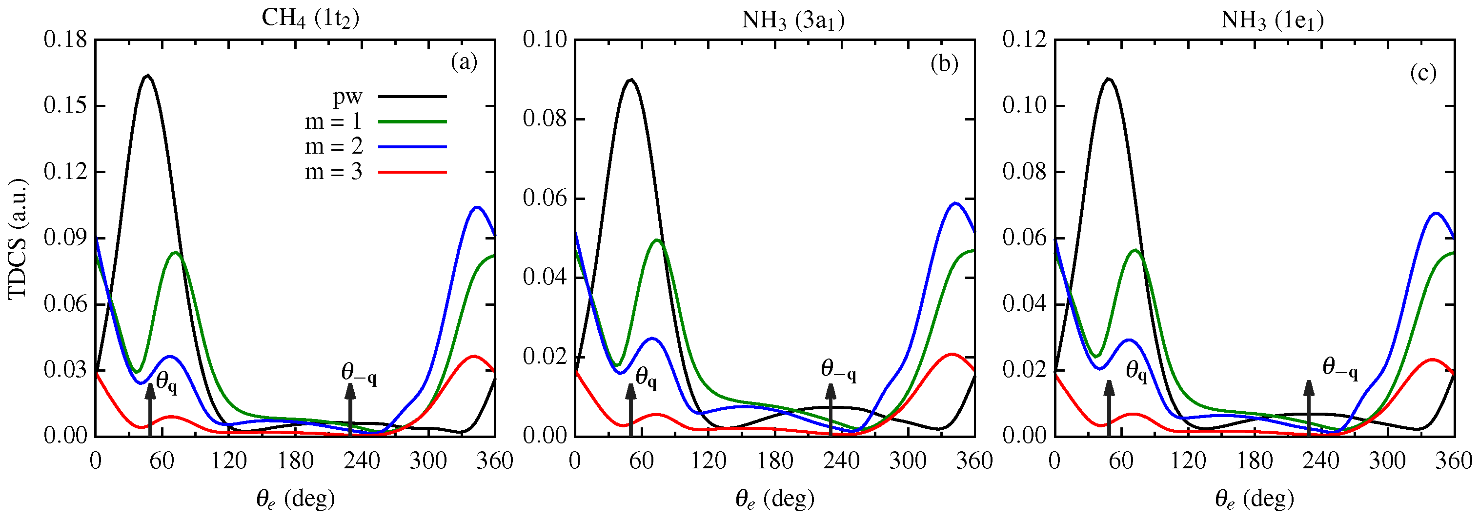
Figure 1 represents the TDCS for the twisted electron impact ionization of the molecular targets CH and NH for the orbitals with a p-type character. We present the TDCS as a function of the ejected electron angle in the coplanar asymmetric geometry for CH (1t) and NH (3a and 1e). For a central collision = 0, we study the effect of OAM number m on the angular profiles of the TDCS for = . In Figure 1, black, green, blue, and red curves represent the TDCS for the plane wave, OAM number m = 1, 2, and 3, respectively, for different molecular orbitals (having p-type character) as mentioned in the frames.
We use the scaling factors 10, 40, and 50 for the TDCS in Figure 1 for m = 1, 2, and 3, respectively, to compare them with the plane wave TDCS. For the molecular orbitals considered in Figure 1, we observe a binary and recoil peak structure in the angular profiles of the TDCS along the momentum transfer directions and for the plane wave. For the twisted electron beam (e, 2e) process, the angular profiles differ from the plane wave TDCS profiles. We observe that the magnitude of the TDCS decreases with an increase in the OAM number m for all the cases (for an explanation describing the decrease in magnitude for fixed and variable, m see [44]). For the outermost molecular orbitals of CH and NH, we observe peaks in the binary and forward regions in the angular profiles with a minimum around the momentum transfer direction (see blue, green, and red curves in Figure 1a,b). The peaks, however, in the binary region are shifted from the momentum transfer direction (see blue, green, and red curves in Figure 1a,b around ).
The angular profiles of the twisted electron TDCS for the p-type orbitals of CH and NH molecules depict a two-peak structure (or peak splitting) in the binary region. This two-peak structure is a characteristic of the p-type orbitals (see green, blue, and red curves in Figure 1 around the momentum transfer direction ). As mentioned in [28,45], the splitting of the binary peak is a characteristic of the p-type orbitals and depends on the kinematical conditions. This splitting of the binary peak in the TDCS for the plane wave (e, 2e) process is explained by the Bethe–Ridge condition. According to Bethe–Ridge [51], when the recoil momentum = is minimal, the binary peak splits. The position of at which is minimal results in a vanishing cross section at that angle, leading to the peak splitting at that . With the present kinematics for the plane wave (e, 2e) on these p-type orbitals, we only obtain a binary and recoil peak structure in the angular profile of the TDCS. However, we observe splitting in the binary peak for the twisted electron impact ionization at the present kinematics. This splitting of the binary peak for the twisted (e, 2e) process is similar to the one observed for Ne (2p) and Ar (3p) in [45]. However, in [45], the splitting was observed for opening angles higher than and here it is at = . In the present study, we observe splitting around momentum transfer direction for the p-type orbitals of both molecules. However, the dominant peak here is directed around the forward direction, (i.e., the peaks are located around = 0° and 360° in Figure 1).
3.2. Ionization from Orbitals of s-Type Character of the Targets
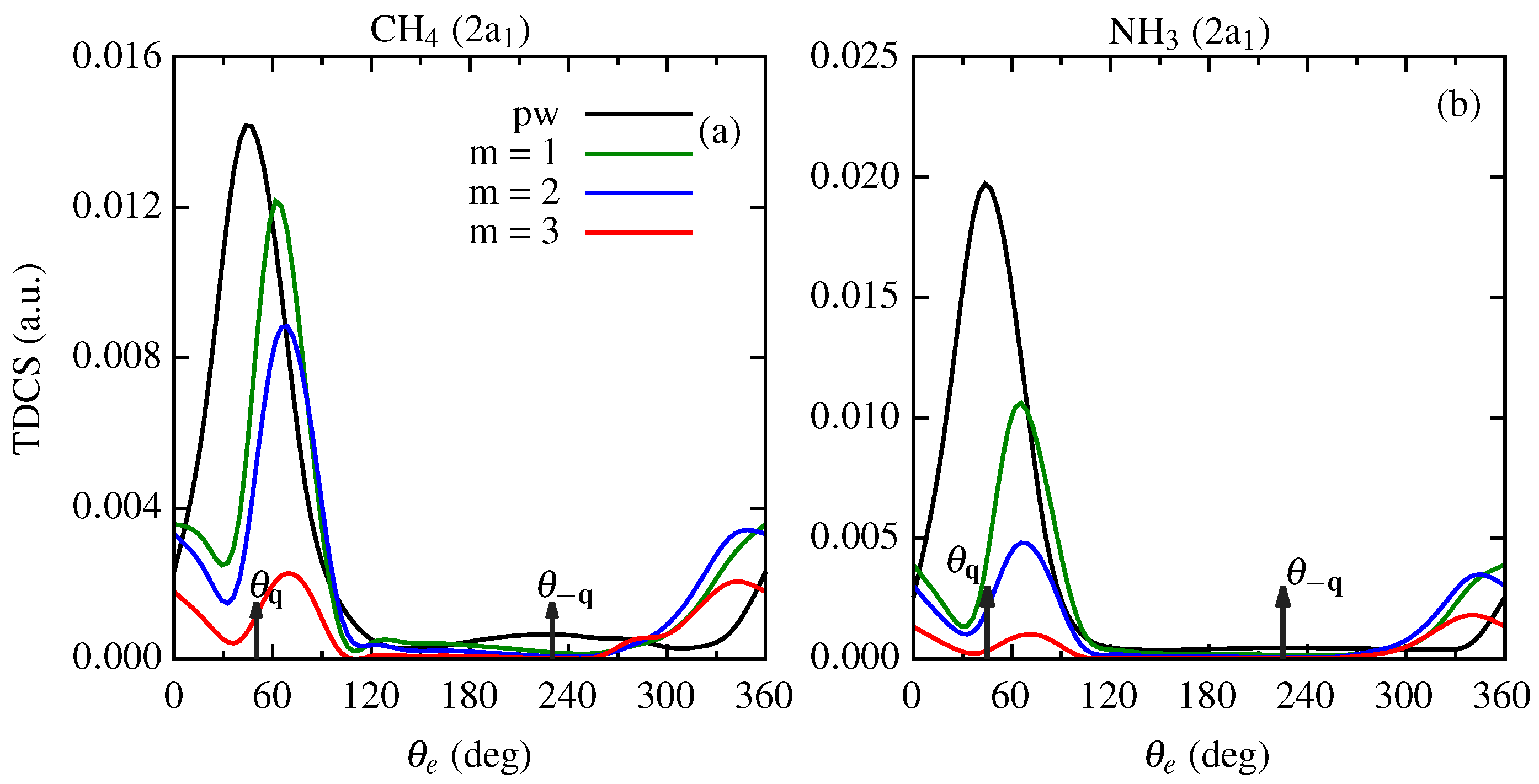
In this subsection, we discuss the results of our calculations for the twisted electron impact ionization TDCS of the molecular targets CH and NH with the orbitals of an s-type character. We present the TDCS as a function of the ejected electron angle in the coplanar asymmetric geometry for CH (2a) and NH (2a). Here, also, we keep = and study the angular profiles of the TDCS for different m.
In Figure 2, we present the angular profiles of TDCS for the molecular orbitals of the s-type character of CH and NH molecules. We present the TDCS as a function of the ejected electron angle in the coplanar asymmetric geometry for CH (2a1) and NH (2a1). We observe that the magnitude of TDCS is smaller than the plane wave TDCS. We use the scaling factors 5, 15, and 30 for the TDCS in Figure 2 for m = 1, 2, and 3, respectively, to compare their respective TDCSs with the plane wave TDCS. Here also, the angular profiles of the TDCS for plane wave depict a binary and recoil peak structure along the momentum transfer directions and . For the twisted electron impact ionization, we observe the binary peak as the dominant peak with the peak position shifted from the momentum transfer direction for all m (see green, blue, and red curves around = in Figure 2). As observed for the p-type orbitals (see Figure 1), we also observe peaks in the forward direction (see green, blue, and red curves around = 0° or 360° region in Figure 2). However, in this case, the peaks are not as prominent as they were for the outer orbitals (see green, blue, and red curves in Figure 1 and Figure 2 around = 360° for comparison).
The above discussion makes it clear that in a twisted electron impact ionization process, there is a transfer of the intrinsic OAM of the beam, and angular profiles of the TDCS show a significant dependence on the OAM number m for = . As can be seen from the above discussion, the order of magnitude of TDCS is significantly lower than that for the plane wave. Furthermore, the ionization studies of the target located at different distances from the vortex line (i.e., keeping impact parameter fixed at a particular value) are difficult. Therefore, it is an experimentally challenging task to measure the TDCS. The above study of the TDCS from the ionization of molecular target located on the propagation axis of the incident twisted electron beam is purely academic. The more realistic scenario for the twisted electron beam is the one where we perform the integration over the impact parameter ((TDCS)).
3.3. Angular Profiles for the (TDCS) for the Macroscopic Molecular Targets
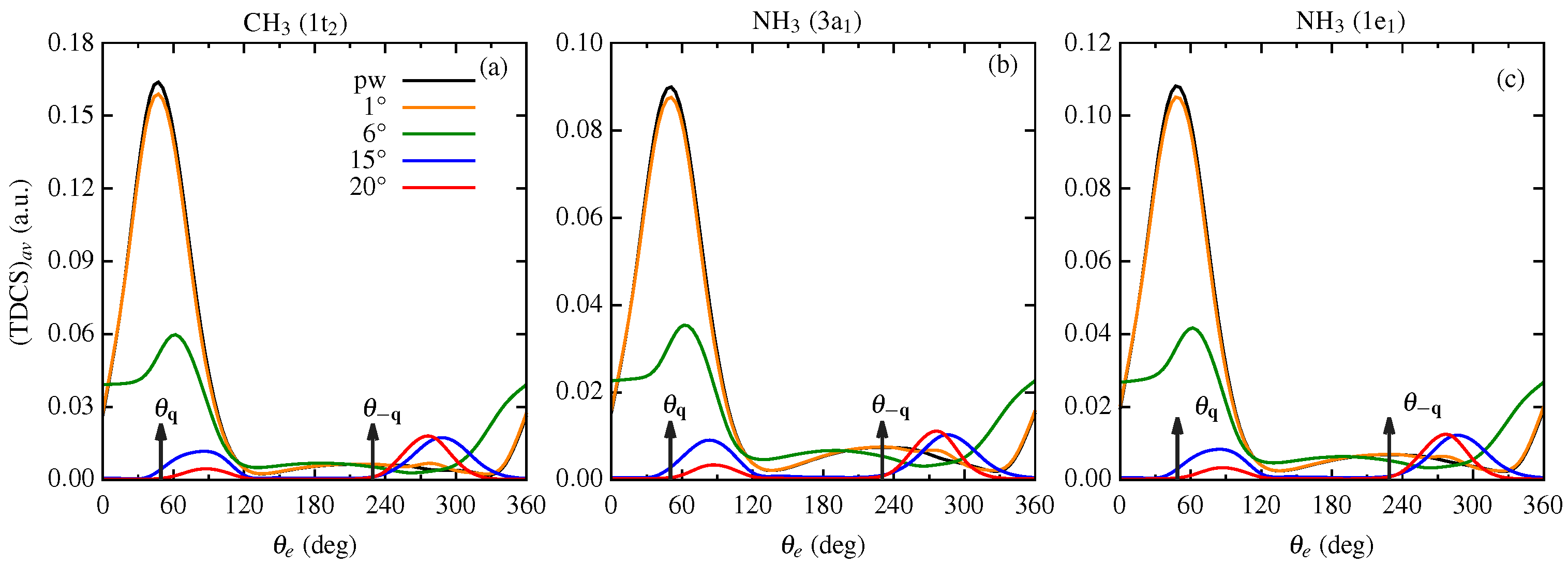
In Figure 3 and Figure 4, we present the angular profiles of the TDCS averaged over the impact parameter , (TDCS), for the CH and NH molecular targets. We discuss the results of the (TDCS) as a function of the ejected electron angle for p-type and s-type orbitals separately. The (TDCS) depends on the opening angle of the incident twisted electron beam. Figure 3 and Figure 4 represent the (TDCS) for the kinematics = 500 eV, = 74 eV and = 6°. We present the results of the (TDCS) for the opening angles 1°, 6°, 15°, and 20° for both molecular targets.
3.3.1. (TDCS) from Orbitals of p-Type Character of the Targets
In this subsection, we present the results of the (TDCS) from the orbitals of the p-type character of CH and NH molecular targets, i.e., 1t of CH and 3a and 1e of NH.
From Figure 3, we observe that for the smallest opening angle, such as = 1°, the angular profile of the (TDCS) is similar to that of the plane wave for all the cases (see orange curves in Figure 3). For = = 6°, the peak in the binary region shifts from the momentum transfer direction for all cases. We observe small peaks in the backward region (see green curves in Figure 3 around = 180°) and a shoulder structure in the forward region (see green curves in Figure 3 around = 0°(or 360°)). The binary peak is shifted from the = direction. On further increasing the opening angles to 15° and 20°, the angular profiles depict a two-peak structure with peaks in the perpendicular directions (see blue and red curves in Figure 3 around = 90° and 270°). The magnitude of the (TDCS) also decreases with an increase in the opening angle.
3.3.2. (TDCS) from Orbitals of s-Type Character of the Targets
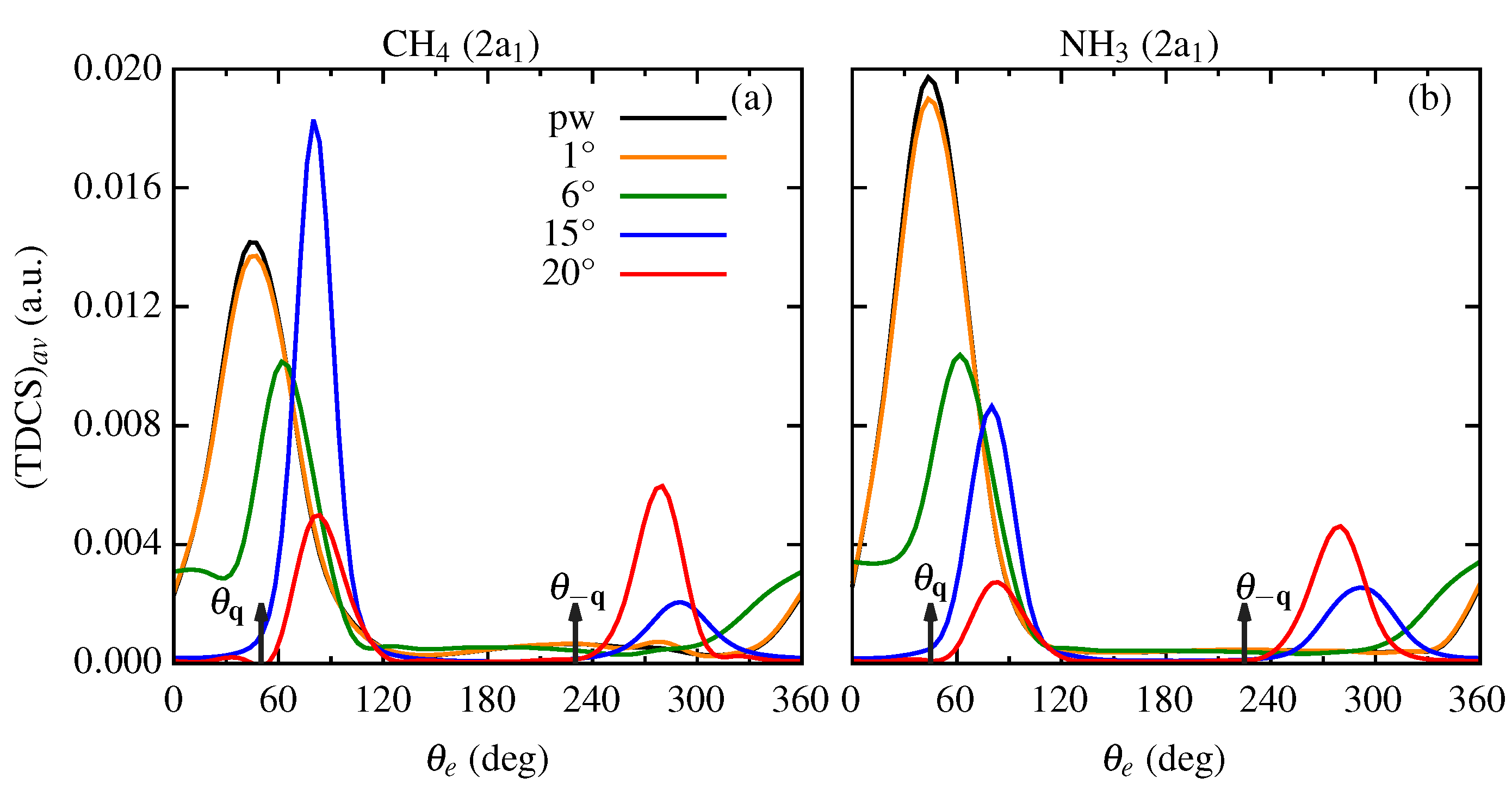
In this subsection, we present the results of the (TDCS) from the orbitals of s-type character of CH and NH molecular targets, i.e., 2a of CH and 2a of NH. Similar to Figure 3, for the s-type orbitals of CH and NH also, the angular profiles of the (TDCS) for the smallest opening angle are similar to the plane wave profile (see orange curves in Figure 4). The angular profiles for the opening angle, same as the scattering angle, (i.e., = = 6°), depict a dominant one-peak structure in the binary region with the peak shifted from the momentum transfer direction (see green curves in Figure 4). For the s-type orbitals, some interesting features are observed at higher opening angles. For the 2a orbital of CH molecule, for opening angle 15°, the magnitude of the dominant peak in (TDCS) is higher than that of the plane wave. In our previous study, we observed a similar phenomenon on the twisted electron impact ionization of a water molecule [44]. However, in [44], we observed that the peaks have a higher magnitude for = case and for p-type orbitals only. For the 2a orbital of NH molecule, the magnitude of the (TDCS) is less than the plane wave TDCS. However, unlike the p-type orbitals, here, for = 15° the prominent peak is in the perpendicular direction (compare blue curves in Figure 3 and Figure 4). On further increasing the opening angle, the magnitude of the (TDCS) decreases, and the peaks shift toward the perpendicular direction (see red curves in Figure 4).
From Section 3.3.1 and Section 3.3.2, we conclude that the angular profiles of the (TDCS) depend on the opening angle .
3.4. TDCS from the Coherent Superposition of Bessel Beams
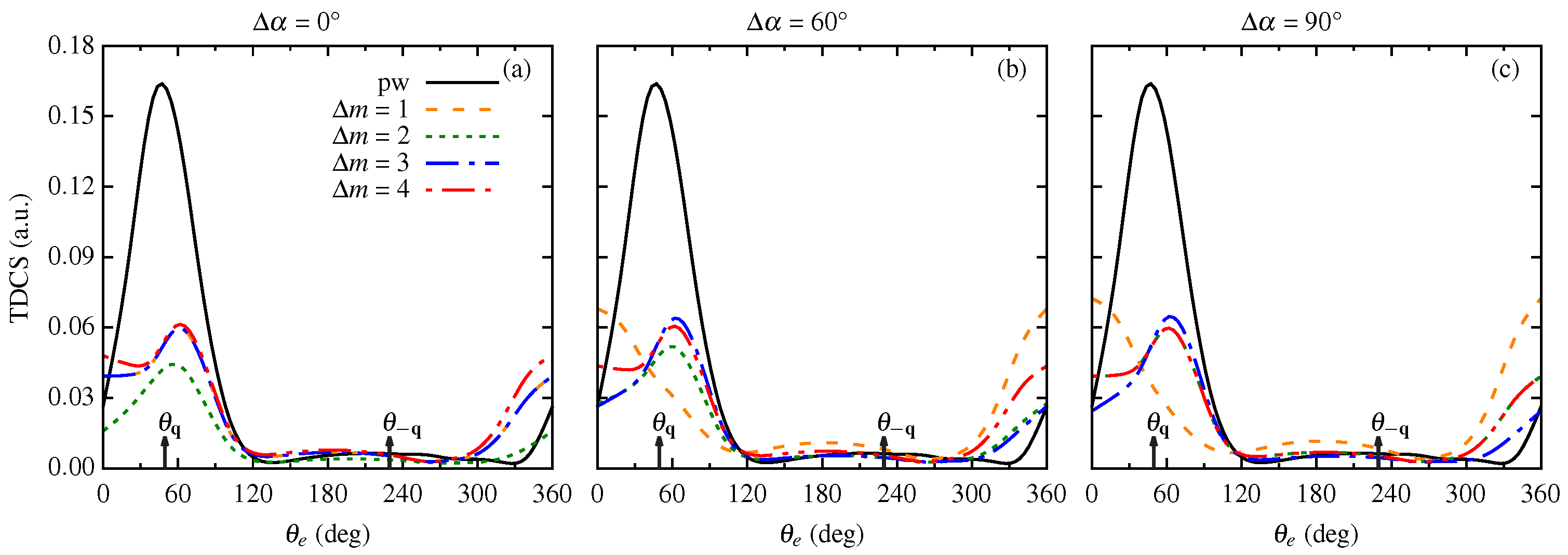
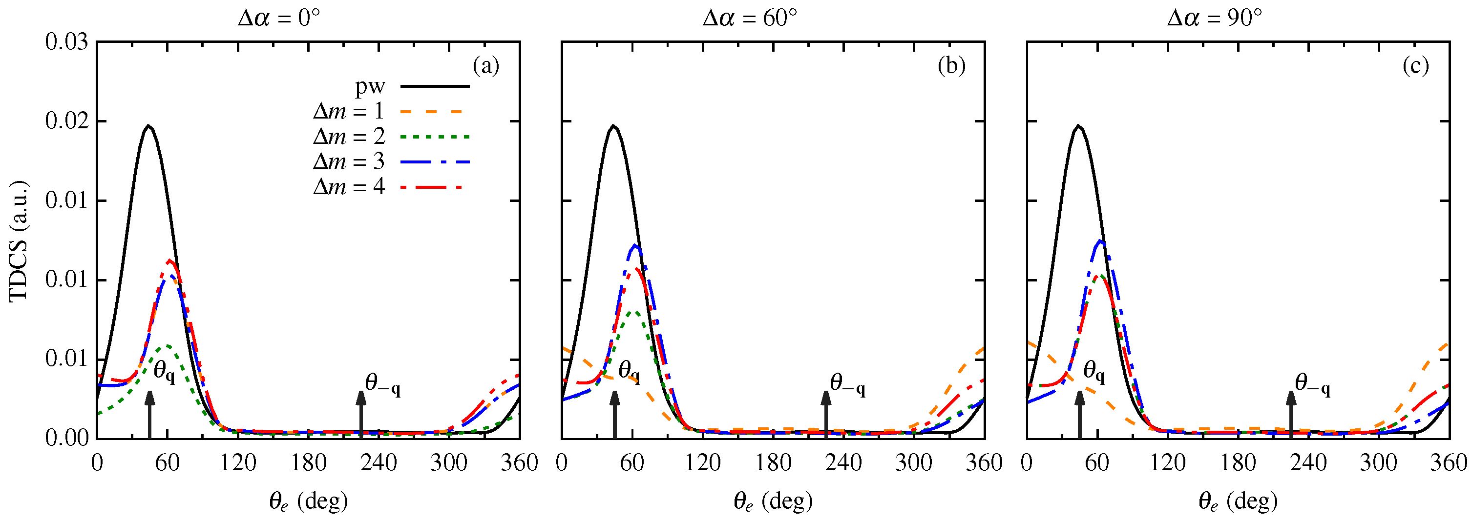
In the previous section, we discussed the twisted electron ionization from the macroscopic molecular target. For such a target, the averaged TDCS is independent of the OAM projection m. However, one can restore and study the OAM sensitivity by considering the incident electron beam as a coherent superposition of two twisted states with different m. The advantage of such a superimposed Bessel beam is that it helps to investigate the effect of OAM projection m on the (e, 2e) process using a twisted electron beam for a realistic scenario. The TDCS now depends not only on the opening angle but also on the OAM projections and the difference in the beam phases . In Figure 5, Figure 6, Figure 7, Figure 8 and Figure 9, we present the results of our calculations for the twisted electron impact ionization from two coherent Bessel beams for the CH and NH molecular targets. We present the results for different (1, 2, 3 and 4) and (0°, 60° and 90°) with the same kinematics as used in Figure 1 and Figure 2. Like the previous sections, we discuss the angular profiles of p-type and s-type orbitals.
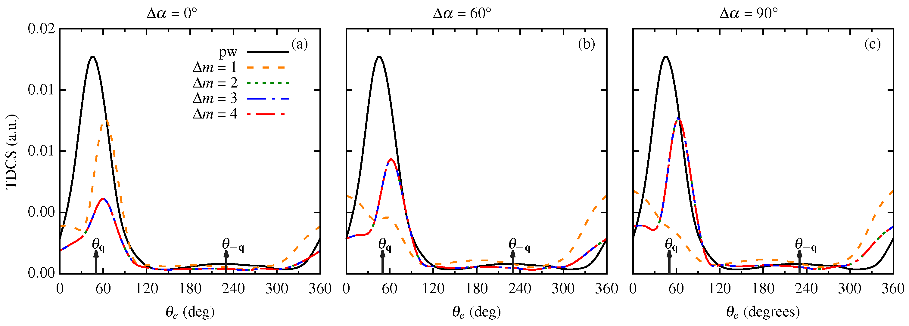
Figure 5, Figure 6 and Figure 7 represent the TDCS from the coherent superposition of two Bessel beams for the molecular orbitals of p-type character, namely, 1t (CH), 3a (NH) and 1e (NH), respectively. For = 0°, i.e., when both the incident twisted electron beams are in phase, we observe peaks in the binary and recoil regions with peak positions shifted from the momentum transfer direction (see Figure 5a, Figure 6a and Figure 7a) for the three p-dominant orbitals. Additionally, the magnitude of TDCS for all the s is less than the plane wave magnitude, with = 2 having the smallest magnitude. As we increase the phase between the Bessel beams, from 0° to 60°, the angular profiles for = 2, 3, and 4 remain almost identical to that of = 0° with a small increment in magnitude (see dotted, dashed–dotted and dashed–dotted–dotted curves in Figure 5, Figure 6 and Figure 7). However, for = 1, the angular profiles show peaks in the forward and backward regions for both = 60° and 90°. (see dashed curves in Figure 5, Figure 6 and Figure 7 around = 0°(360°) and 180°). For = 1 and = 0°, we observe peaks in the binary and recoil regions with the lowest magnitude of TDCS. On further increasing the phase between incident beams to 90°, we observe that the angular profile structure remains the same as that for = 60°, but there is a slight increase in the magnitude for all of the OAM projections (see dashed curves in Figure 5b,c, Figure 6b,c and Figure 7b,c).
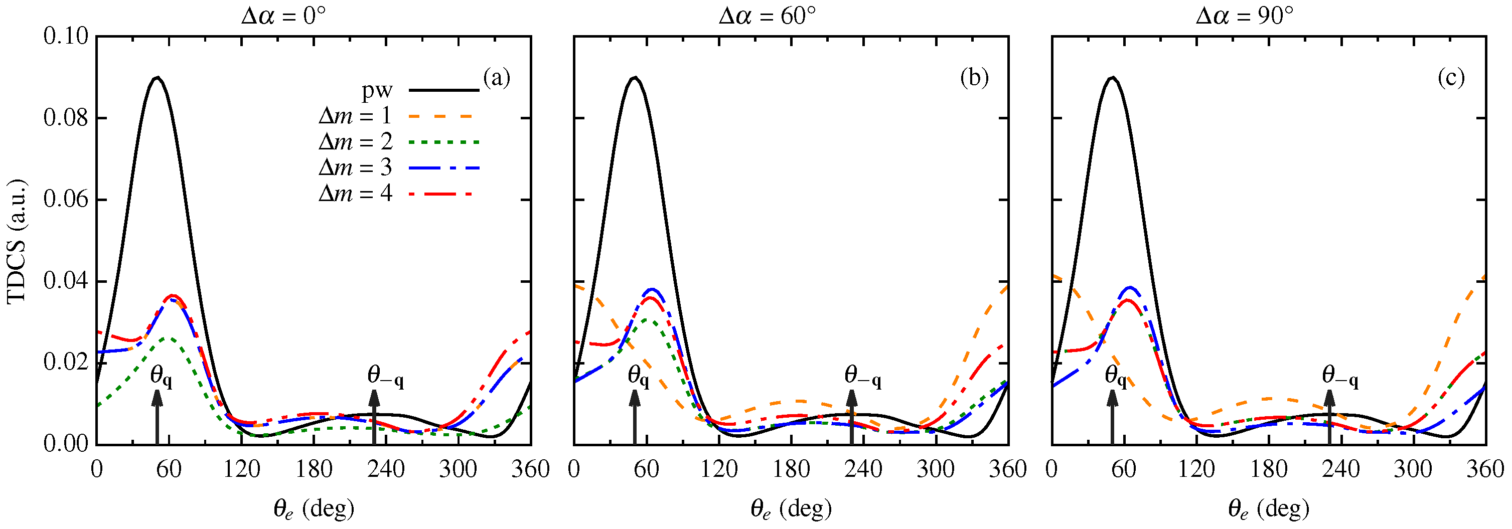
Figure 8 and Figure 9 represent the TDCS from the coherent superposition of two Bessel beams for the molecular orbitals of s-type character, namely, 2a (CH) and 2a (NH), respectively. For the 2a orbital of CH molecule, we observe the binary and recoil peak structure with the same magnitude of TDCS for = 2, 3, and 4 at different phases of the incident twisted electron beams as shown in Figure 8. For these values of , the peak position shifts to a perpendicular direction with an increase in the phase between the incident twisted electron beams (see dotted, dashed–dotted, and dashed–dotted–dotted curves in Figure 8b,c). For the in-phase incidence of the twisted electron beams, the magnitude of the TDCS for = 1 is highest compared to the other s. The binary peak structure disappears with a further increment in the phase between the incident beams. We observe peaks in the forward and backward directions (see dashed curves for different s in Figure 8).
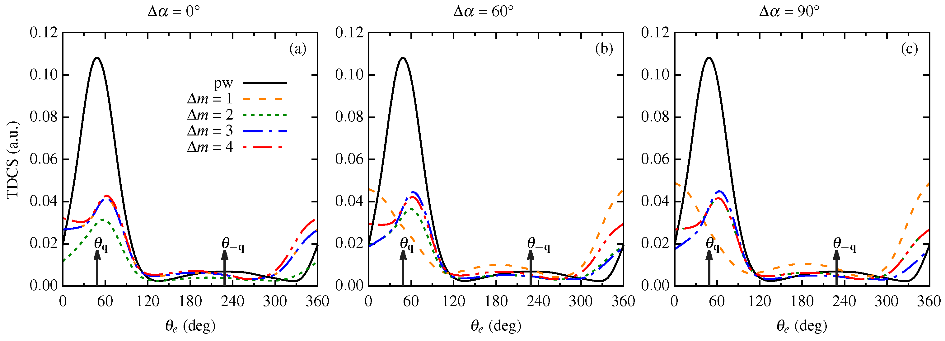
The results of our calculations for the 2a orbital of the NH molecule for superposed Bessel beams are fairly similar to the ones observed for the p-type orbitals (compare Figure 5 and Figure 9). For = 0°, the angular profile of TDCS maintains the binary peak structure of the plane wave for the s considered, with = 2 having the lowest magnitude. On further increasing the phase between incident beams, = 2, 3, and 4 maintains the binary peak structure of the angular profile with the peak shifted from the momentum transfer direction and an enhancement in the magnitude of TDCS (see dotted, dashed–dotted and dashed–dotted–dotted curves in Figure 9). However, for = 1, the binary peak structure in the angular profile of the TDCS disappears with an increment in the phase angle, and we observe peaks in the forward and backward directions (see dashed curves in Figure 9 around = 0°(360°) and 180°).
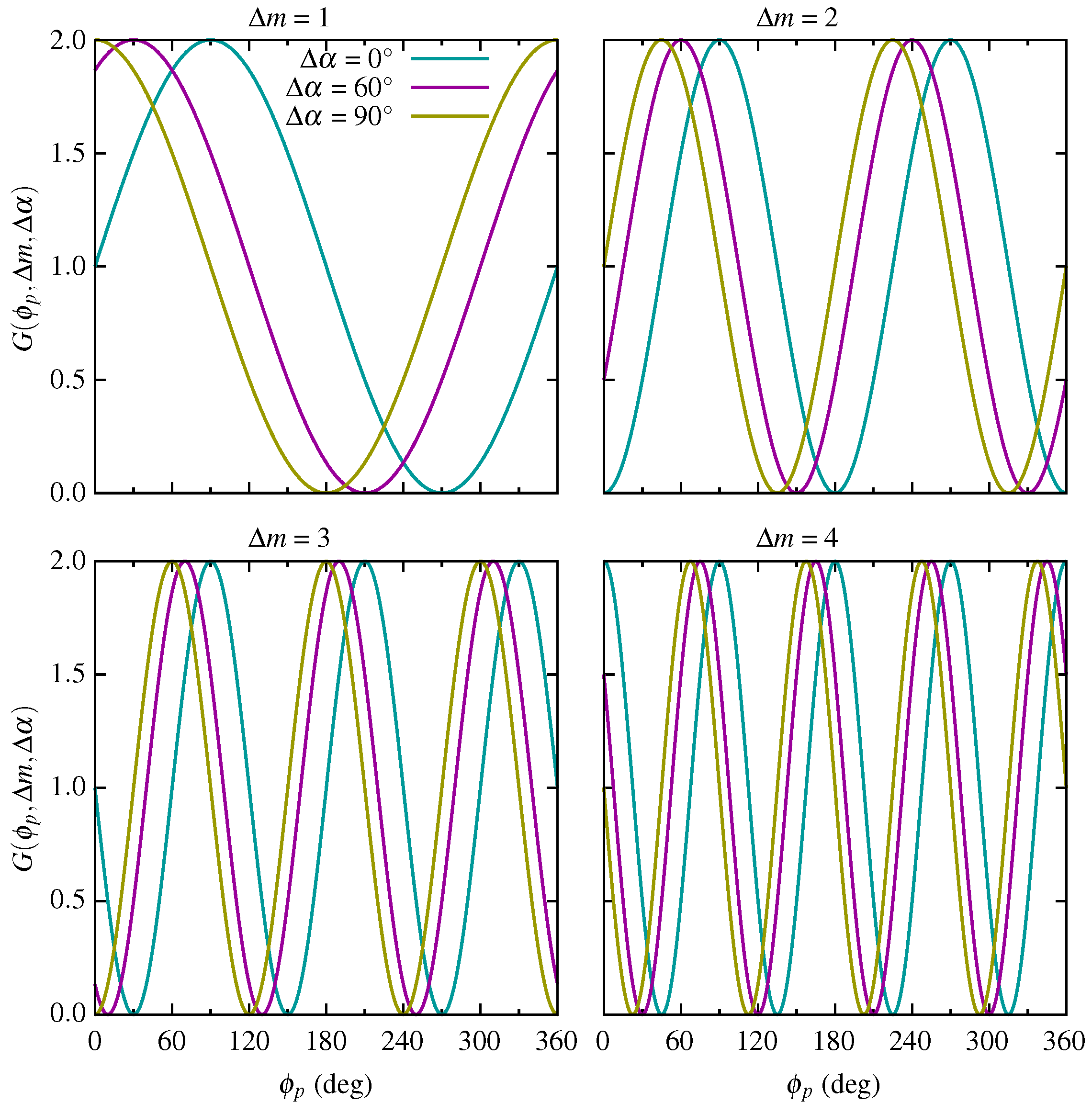
From the superposition of the twisted beams, we observe that the TDCS is sensitive to the relative phase and the difference of the OAM of the incident beams through an interference term (see Figure 5, Figure 6, Figure 7, Figure 8 and Figure 9). However, this sensitiveness is more prominent for = 1 (see dashed yellow curves in Figure 5, Figure 6, Figure 7, Figure 8 and Figure 9). This dependence can be explained by the fact that due to the superposition of coherent Bessel beams, the modified transverse intensity profile is no longer similar to that of the Bessel beam [52]. Additionally, due to superposition, the azimuthal symmetry of the Bessel beam changes with the relative phase between the beams [50,52]. This effect of and is visible on the angular profiles of the TDCS for the CH and NH molecules. From Equation (21), we have that (TDCS) depends on the factor . In Figure 10, we plot as a function of for different values of and to understand the effect of this factor on the cross section. From Figure 10, we observe that the factor G(, , ) shifts with a phase change for a fixed . However, this shift in the position is more prominent for a small value of ( = 1). The shift in the peaks exists for other values of as well, but with an increase in , the relative shift between the peaks is small compared to = 1. Thus, in Figure 5, Figure 6, Figure 7, Figure 8 and Figure 9, we observe a significant change in the angular profiles of the (TDCS) for = 60° and 90° for = 1 only. The angular profiles with = 1 show that the interference term significantly affects the cross section. Taken together, the angular profiles for the superposition of coherent Bessel beams reflect the effect of and .
4. Conclusions
We presented the theoretical study of the triple differential cross sections (TDCSs) for an (e, 2e) process for CH and NH molecular targets by the twisted electron beam. We studied the angular distributions of the TDCS for the coplanar asymmetric geometry in the first Born approximation for the twisted electron beam. We studied the influence of the OAM number m on the angular profiles of the TDCS for the opening angle, the same as the scattering angle ( = ). In this paper, we extended our previous model for the twisted electron impact ionization for the water molecule [44] to the CH and NH molecular targets. We studied the angular profiles for the p-type and s-type molecular orbitals of CH and NH. For the present geometry, the angular profiles of the TDCS (for both p-type and s-type) peak around (binary peak) and (recoil peak) for the plane wave. However, the angular profiles of the TDCS show significant deviation from the plane wave TDCS angular profiles for the molecular orbitals considered. The twisted electron TDCS retrieves the characteristic two-peak structure for the 1e orbital of NH which is absent in the plane wave angular distributions of the TDCS. For the s-type orbitals, the angular distributions are shifted from the momentum transfer direction.
For a macroscopic molecular target, we discuss the (TDCS) (averaged over the impact parameter b) as a function of the opening angle of the twisted electron beam. The results show that the angular profiles of (TDCS) significantly depend on the opening angle () of the twisted electron beam. (TDCS) is similar to the plane wave TDCS for a smaller opening angle ( = 1°). For opening angles higher than the scattering angle, i.e., 15° and 20°, the peaks in the angular profiles shift to the perpendicular directions. We also discussed the angular profiles for the coherent superposition of two Bessel beams. The angular profiles for superposed Bessel beams show the dependence of the TDCS on the OAM projection m.
Our present investigation of CH and NH molecule is based on our previous studies on HO. In our earlier study [44], we focused on the angular profiles of the TDCS for different molecular orbitals of the water molecule, which constituted mainly p-type orbitals. The angular profiles of the TDCS for an incident plane wave depicted peak splitting in the p-type orbitals, while there was no peak splitting for angular profiles of the twisted electron beam. In the present communication, we study the cross sections for both s- and p-type orbitals here. The angular profiles for the twisted electron beam, as shown in Section 3, exhibit significantly different observations than those we studied earlier, for example, the splitting of the prominent peaks for p-type orbitals for the twisted electron case contrary to the TDCS (where we did not observe the splitting in the twisted electron case for = case), a significant deviation of the angular profiles of the (TDCS) for the opening angle other than = , etc. The results suggest that the twisted electron beams present a better tool than the plane wave beam to image the electron cloud and study the molecular structure.
Author Contributions
Conceptualization, theoretical calculations, and code development: N.D. under the guidance of R.C. Code execution and data analysis: N.D. and N. Preparation of manuscript: all authors. All authors have read and agreed to the published version of the manuscript.
Funding
This research was funded by Science and Engineering Research Board, Department of Science and Technology, Government of India under grant number CRG/2021/003828.
Data Availability Statement
The data presented in this study are available on request from the corresponding author.
Conflicts of Interest
The authors declare no conflict of interest.
References
- Torres, J.P.; Torner, L. Twisted Photons: Applications of Light with Orbital Angular Momentum; John Wiley & Sons: Hoboken, NJ, USA, 2011. [Google Scholar]
- Molina-Terriza, G.; Torres, J.P.; Torner, L. Twisted photons. Nat. Phys. 2007, 3, 305–310. [Google Scholar] [CrossRef]
- Bliokh, K.; Ivanov, I.; Guzzinati, G.; Clark, L.; Van Boxem, R.; Béché, A.; Juchtmans, R.; Alonso, M.; Schattschneider, P.; Nori, F.; et al. Theory and applications of free-electron vortex states. Phys. Rep. 2017, 690, 1–70. [Google Scholar] [CrossRef]
- Lloyd, S.M.; Babiker, M.; Thirunavukkarasu, G.; Yuan, J. Electron vortices: Beams with orbital angular momentum. Rev. Mod. Phys. 2017, 89, 035004. [Google Scholar] [CrossRef]
- Larocque, H.; Kaminer, I.; Grillo, V.; Leuchs, G.; Padgett, M.J.; Boyd, R.W.; Segev, M.; Karimi, E. ‘Twisted’ electrons. Contemp. Phys. 2018, 59, 126–144. [Google Scholar] [CrossRef]
- Ivanov, I.P. Promises and challenges of high-energy vortex states collisions. Prog. Part. Nucl. Phys. 2022, 127, 103987. [Google Scholar] [CrossRef]
- Bliokh, K.Y.; Bliokh, Y.P.; Savel’ev, S.; Nori, F. Semiclassical Dynamics of Electron Wave Packet States with Phase Vortices. Phys. Rev. Lett. 2007, 99, 190404. [Google Scholar] [CrossRef]
- Uchida, M.; Tonomura, A. Generation of electron beams carrying orbital angular momentum. Nature 2010, 464, 737–739. [Google Scholar] [CrossRef]
- Verbeeck, J.; Tian, H.; Schattschneider, P. Production and application of electron vortex beams. Nature 2010, 467, 301–304. [Google Scholar] [CrossRef]
- Mafakheri, E.; Tavabi, A.H.; Lu, P.H.; Balboni, R.; Venturi, F.; Menozzi, C.; Gazzadi, G.C.; Frabboni, S.; Sit, A.; Dunin-Borkowski, R.E.; et al. Realization of electron vortices with large orbital angular momentum using miniature holograms fabricated by electron beam lithography. Appl. Phys. Lett. 2017, 110, 093113. [Google Scholar] [CrossRef]
- Tavabi, A.H.; Rosi, P.; Roncaglia, A.; Rotunno, E.; Beleggia, M.; Lu, P.H.; Belsito, L.; Pozzi, G.; Frabboni, S.; Tiemeijer, P.; et al. Generation of electron vortex beams with over 1000 orbital angular momentum quanta using a tunable electrostatic spiral phase plate. Appl. Phys. Lett. 2022, 121, 073506. [Google Scholar] [CrossRef]
- Juchtmans, R.; Béché, A.; Abakumov, A.; Batuk, M.; Verbeeck, J. Using electron vortex beams to determine chirality of crystals in transmission electron microscopy. Phys. Rev. B 2015, 91, 094112. [Google Scholar] [CrossRef]
- Juchtmans, R.; Verbeeck, J. Local orbital angular momentum revealed by spiral-phase-plate imaging in transmission-electron microscopy. Phys. Rev. A 2016, 93, 023811. [Google Scholar] [CrossRef]
- Thirunavukkarasu, G.; Thirunavukkarasu, G.; Yuan, J.; Babiker, M. Observation of gold nanoparticles movements under sub-10 nm vortex electron beams in an aberration corrected TEM. In Proceedings of the 15th European Microscopy Congresss; Stokes, D., Hutchison, J., Eds.; Royal Microscopical Society: Manchester, UK, 2012. [Google Scholar]
- Jesacher, A.; Fürhapter, S.; Bernet, S.; Ritsch-Marte, M. Shadow Effects in Spiral Phase Contrast Microscopy. Phys. Rev. Lett. 2005, 94, 233902. [Google Scholar] [CrossRef]
- Serbo, V.; Ivanov, I.P.; Fritzsche, S.; Seipt, D.; Surzhykov, A. Scattering of twisted relativistic electrons by atoms. Phys. Rev. A 2015, 92, 012705. [Google Scholar] [CrossRef]
- Dhankhar, N.; Choubisa, R. Electron impact single ionization of hydrogen molecule by twisted electron beam. J. Phys. B At. Mol. Opt. Phys. 2020, 54, 015203. [Google Scholar] [CrossRef]
- Gong, M.; Cheng, Y.; Zhang, S.B.; Chen, X. Twisted-electron-impact single ionization of an H2O molecule by multicenter distorted-wave calculations. Phys. Rev. A 2022, 106, 012818. [Google Scholar] [CrossRef]
- Bartschat, K.; Kushner, M.J. Electron collisions with atoms, ions, molecules, and surfaces: Fundamental science empowering advances in technology. Proc. Natl. Acad. Sci. USA 2016, 113, 7026–7034. [Google Scholar] [CrossRef]
- Dunn, W.B. Chapter two—Mass Spectrometry in Systems Biology: An Introduction. In Methods in Systems Biology; Methods in Enzymology; Jameson, D., Verma, M., Westerhoff, H.V., Eds.; Academic Press: Cambridge, MA, USA, 2011; Volume 500, pp. 15–35. [Google Scholar] [CrossRef]
- Girazian, Z.; Mahaffy, P.; Lillis, R.J.; Benna, M.; Elrod, M.; Fowler, C.M.; Mitchell, D.L. Ion Densities in the Nightside Ionosphere of Mars: Effects of Electron Impact Ionization. Geophys. Res. Lett. 2017, 44, 11248–11256. [Google Scholar] [CrossRef]
- Kynienė, A.; Kučas, S.; Masys, Š.; Jonauskas, V. Electron-impact ionization of Fe8+. A&A 2019, 624, A14. [Google Scholar] [CrossRef]
- Caleman, C.; Ortiz, C.; Marklund, E.; Bultmark, F.; Gabrysch, M.; Parak, F.G.; Hajdu, J.; Klintenberg, M.; Tîmneanu, N. Radiation damage in biological material: Electronic properties and electron impact ionization in urea. EPL (Europhys. Lett.) 2009, 85, 18005. [Google Scholar] [CrossRef]
- Yavuz, M.; Okumus, N.; Ozer, Z.N.; Ulu, M.; Dogan, M.; Sahlaoui, M.; Benmansour, H.; Bouamoud, M. Double Differential Cross Sections for Methane Molecules at Intermediate Energies. J. Phys. Conf. Ser. 2014, 488, 052031. [Google Scholar] [CrossRef]
- Yavuz, M.; Ozer, Z.N.; Ulu, M.; Champion, C.; Dogan, M. Experimental and theoretical double differential cross sections for electron impact ionization of methane. J. Chem. Phys. 2016, 144, 164305. [Google Scholar] [CrossRef]
- Tachino, C.A.; Monti, J.M.; Fojón, O.A.; Champion, C.; Rivarola, R.D. Single electron ionization of NH3 and CH4 by swift proton impact. J. Phys. Conf. Ser. 2015, 583, 012020. [Google Scholar] [CrossRef]
- Tóth, I.; Nagy, L.; Campeanu, R.I. Triple-differential cross sections for the ionization of NH3 by positron impact. Eur. Phys. J. D 2016, 70, 170. [Google Scholar] [CrossRef]
- Lahmam-Bennani, A.; Naja, A.; Casagrande, E.M.S.; Okumus, N.; Cappello, C.D.; Charpentier, I.; Houamer, S. Dynamics of electron impact ionization of the outer and inner valence (1t2 and 2a1) molecular orbitals of CH4 at intermediate and large ion recoil momentum. J. Phys. B At. Mol. Opt. Phys. At. Mol. Opt. Phys. 2009, 42, 165201. [Google Scholar] [CrossRef]
- Mir, R.E.; Casagrande, E.M.S.; Naja, A.; Cappello, C.D.; Houamer, S.; Omar, F.E. Triple differential cross sections for the ionization of the valence states of NH3 by electron impact. J. Phys. B At. Mol. Opt. Phys. 2015, 48, 175202. [Google Scholar] [CrossRef]
- Mouawad, L.; El Bitar, Z.; Osman, A.; Khalil, M.; Hervieux, P.A.; Dal Cappello, C. Triply Differential Ionization Cross Sections of atomic and molecular targets by single electron impact. EPJ Web Conf. 2018, 170, 01012. [Google Scholar] [CrossRef]
- Bouchikhi, A.; Sahlaoui, M.; Lasri, B.; Sekkal, A.; Bouamoud, M. Electron-impact ionization of the CH4 and NH3 molecules in coplanar symmetric and asymmetric geometries. J. Phys. B At. Mol. Opt. Phys. 2018, 52, 015201. [Google Scholar] [CrossRef]
- Nixon, K.L.; Murray, A.J.; Chaluvadi, H.; Ning, C.; Madison, D.H. Low energy (e,2e) studies from CH4: Results from symmetric coplanar experiments and molecular three-body distorted wave theory. J. Chem. Phys. 2011, 134, 174304. [Google Scholar] [CrossRef] [PubMed]
- Ali, E.; Granados, C.; Sakaamini, A.; Harvey, M.; Ancarani, L.U.; Murray, A.J.; Dogan, M.; Ning, C.; Colgan, J.; Madison, D. Triple differential cross sections for electron-impact ionization of methane at intermediate energy. J. Chem. Phys. 2019, 150, 194302. [Google Scholar] [CrossRef]
- Nixon, K.L.; Murray, A.J.; Chaluvadi, H.; Ning, C.; Colgan, J.; Madison, D.H. Low energy (e,2e) coincidence studies of NH3: Results from experiment and theory. J. Chem. Phys. 2013, 138, 174304. [Google Scholar] [CrossRef] [PubMed]
- Tóth, I.; Nagy, L. Triple-differential cross-section calculations for the ionization of CH4 by electron impact. J. Phys. B At. Mol. Opt. Phys. At. Mol. Opt. Phys. 2010, 43, 135204. [Google Scholar] [CrossRef]
- Lin, C.Y.; McCurdy, C.W.; Rescigno, T.N. Theoretical study of (e,2e) from outer- and inner-valence orbitals of CH4: A complex Kohn treatment. Phys. Rev. A 2014, 89, 052718. [Google Scholar] [CrossRef]
- Castro, C.M.G. Application of Generalized Sturmian Basis Functions to Molecular Systems. Ph.D. Thesis, Université de Lorraine, Metz, France, 2016. [Google Scholar]
- Granados-Castro, C.M.; Ancarani, L.U. Electron impact ionization of the outer valence orbital 1t2 of CH4. Eur. Phys. J. D 2017, 71, 65. [Google Scholar] [CrossRef]
- Gong, M.; Li, X.; Zhang, S.B.; Liu, L.; Wu, Y.; Wang, J.; Qu, Y.; Chen, X. Theoretical study of (e,2e) processes for valence orbitals of CH4 using a multicenter distorted-wave method. Phys. Rev. A 2017, 96, 042703. [Google Scholar] [CrossRef]
- Houamer, S.; Chinoune, M.; Cappello, C.D. Theoretical study of (e, 2e) process of atomic and molecular targets*. Eur. Phys. J. D 2017, 71, 17. [Google Scholar] [CrossRef]
- Mir, R.E.; Kaja, K.; Naja, A.; Casagrande, E.M.S.; Houamer, S.; Cappello, C.D. New investigation of the electron-impact ionization of the intermediate valence state of ammonia. J. Phys. B At. Mol. Opt. Phys. 2020, 54, 015201. [Google Scholar] [CrossRef]
- Harris, A.L.; Plumadore, A.; Smozhanyk, Z. Ionization of hydrogen by electron vortex beam. J. Phys. B At. Mol. Opt. Phys. 2019, 52, 094001. [Google Scholar] [CrossRef]
- Plumadore, A.; Harris, A.L. Projectile transverse momentum controls emission in electron vortex ionization collisions. J. Phys. B At. Mol. Opt. Phys. 2020, 53, 205205. [Google Scholar] [CrossRef]
- Dhankhar, N.; Choubisa, R. Triple-differential cross section for the twisted-electron-impact ionization of the water molecule. Phys. Rev. A 2022, 105, 062801. [Google Scholar] [CrossRef]
- Dhankhar, N.; Banerjee, S.; Choubisa, R. Twisted electron impact single ionization coincidence cross-sections for noble gas atoms. J. Phys. At. Mol. Opt. Phys. At. Mol. Opt. Phys. 2022, 55, 165202. [Google Scholar] [CrossRef]
- Mandal, A.; Dhankhar, N.; Sébilleau, D.; Choubisa, R. Semirelativistic (e,2e) study with a twisted electron beam on Cu and Ag. Phys. Rev. A 2021, 104, 052818. [Google Scholar] [CrossRef]
- Moccia, R. One-Center Basis Set SCF MO’s. I. HF, CH4, and SiH4. J. Chem. Phys. 1964, 40, 2164–2176. [Google Scholar] [CrossRef]
- Moccia, R. One-Center Basis Set SCF MO’s. II. NH3, NH4+, PH3, PH4+. J. Chem. Phys. 1964, 40, 2176–2185. [Google Scholar] [CrossRef]
- Champion, C.; Hanssen, J.; Hervieux, P.A. Influence of molecular orientation on the multiple differential cross sections for the (e,2e) process on a water molecule. Phys. Rev. A 2005, 72, 059906. [Google Scholar] [CrossRef]
- Karlovets, D.V.; Kotkin, G.L.; Serbo, V.G.; Surzhykov, A. Scattering of twisted electron wave packets by atoms in the Born approximation. Phys. Rev. A 2017, 95, 032703. [Google Scholar] [CrossRef]
- Khajuria, Y.; Tripathi, D.N. Geometry effects on the (e,2e) triple differential cross sections of Li+, Na+, and K+. Phys. Rev. A 1999, 59, 1197–1207. [Google Scholar] [CrossRef]
- Surzhykov, A.; Seipt, D.; Serbo, V.G.; Fritzsche, S. Interaction of twisted light with many-electron atoms and ions. Phys. Rev. A 2015, 91, 013403. [Google Scholar] [CrossRef]
Figure 1.
Angular profiles of the TDCS as a function of the ejected electron angle for the twisted electron (e, 2e) process from the orbitals of p-type character of CH and NH in the coplanar asymmetric geometry. The kinematics used here is = 500 eV, = 74 eV, = 6° and = . The sub-figure (a) is for the 1t orbital of CH molecular target, while the sub-figures (b,c) are for the 3a and 1e molecular orbitals of the NH molecule, respectively. The black, green, blue, and red curves represent the TDCS for plane wave, m = 1, 2, and 3, respectively. For all the sub-figures, we used the multiplicative factors 10, 40, and 50 for m = 1, 2, and 3, respectively. and represent the direction of momentum transfer and recoil momentum.

Figure 2.
Same as Figure 1, except the angular profiles here are for the orbitals of s-type character of CH and NH in the co-planar asymmetric geometry.
Figure 2.
Same as Figure 1, except the angular profiles here are for the orbitals of s-type character of CH and NH in the co-planar asymmetric geometry.

Figure 3.
(TDCS) plotted as a function of the ejected electron angle for the plane wave (solid line) and twisted electron beam for different opening angles as shown in the frames of each sub-figure. The kinematics is the same as in Figure 1. The black, orange, green, blue, and red curves represent the TDCS for plane wave, = 1°, 6°, 15°, and 20°, respectively.

Figure 4.
(TDCS) plotted as a function of the ejected electron angle for the plane wave (solid line) and twisted electron beam for different opening angles and molecular orbitals as shown in the frames of each sub-figure. The kinematics is same as used in Figure 2.
Figure 4.
(TDCS) plotted as a function of the ejected electron angle for the plane wave (solid line) and twisted electron beam for different opening angles and molecular orbitals as shown in the frames of each sub-figure. The kinematics is same as used in Figure 2.

Figure 5.
TDCS as a function of ejected electron angle for the twisted electron (e, 2e) process on the 1t orbital of CH molecular target. The results are for a coherent superposition of two Bessel beams with different OAM projections and phases (as shown in the sub-figures). We keep the kinematics the same as Figure 1. The solid, dashed, dotted, dashed–dotted and dashed–dotted–dotted curves are for plane wave, = 1, 2, 3 and 4, respectively.

Figure 6.
Same as Figure 5, except the results are for 3a molecular orbital of NH.
Figure 6.
Same as Figure 5, except the results are for 3a molecular orbital of NH.

Figure 7.
Same as Figure 5, except the results are for 1e molecular orbital of NH.
Figure 7.
Same as Figure 5, except the results are for 1e molecular orbital of NH.

Figure 8.
Same as Figure 5, except the results are for 2a molecular orbital of CH.
Figure 8.
Same as Figure 5, except the results are for 2a molecular orbital of CH.

Figure 9.
Same as Figure 5, except the results are for 2a molecular orbital of NH.
Figure 9.
Same as Figure 5, except the results are for 2a molecular orbital of NH.

Figure 10.
G(, , ) factor as a function of the angle for different values of relative phase () and OAM difference ().
Figure 10.
G(, , ) factor as a function of the angle for different values of relative phase () and OAM difference ().

Disclaimer/Publisher’s Note: The statements, opinions and data contained in all publications are solely those of the individual author(s) and contributor(s) and not of MDPI and/or the editor(s). MDPI and/or the editor(s) disclaim responsibility for any injury to people or property resulting from any ideas, methods, instructions or products referred to in the content. |
© 2023 by the authors. Licensee MDPI, Basel, Switzerland. This article is an open access article distributed under the terms and conditions of the Creative Commons Attribution (CC BY) license (https://creativecommons.org/licenses/by/4.0/).
Share and Cite
MDPI and ACS Style
Dhankhar, N.; Neha; Choubisa, R. Dynamics of Twisted Electron Impact Ionization of CH4 and NH3 Molecule. Atoms 2023, 11, 82. https://doi.org/10.3390/atoms11050082
AMA Style
Dhankhar N, Neha, Choubisa R. Dynamics of Twisted Electron Impact Ionization of CH4 and NH3 Molecule. Atoms. 2023; 11(5):82. https://doi.org/10.3390/atoms11050082
Chicago/Turabian StyleDhankhar, Nikita, Neha, and Rakesh Choubisa. 2023. "Dynamics of Twisted Electron Impact Ionization of CH4 and NH3 Molecule" Atoms 11, no. 5: 82. https://doi.org/10.3390/atoms11050082
Note that from the first issue of 2016, this journal uses article numbers instead of page numbers. See further details here.