1. Introduction
With the advent of quantum computing, the second quantum revolution has been ushered in [
1]. Quantum memory [
2], quantum information processing [
3], etc., are rapidly becoming modernized to improvise the performance of computing in this era. The fundamental building block of such quantum tools is isolated atoms or molecules; the isolation is achieved through quantum confinement. Entrapment of atoms in fullerene molecule is one such successful confinement mechanism [
4], and the Paul trap is another mechanism by which a cluster of molecules can be isolated [
5]. Crossed laser beams create a dipole field, and atoms can also be isolated in such traps [
6]. Atoms encapsulated in fullerenes, dipole traps, Paul traps, etc., are potential candidates for qubits, which can be used in quantum computers [
7,
8,
9]. Experiments to realize quantum computers using isolated atoms are rapidly being developed [
10].
Benioff pointed out in an early work that triggering a quantum computer’s register involves a physical process; it is, of course, not just mathematical manipulation by matrices that represents the quantum gates [
11,
12]. A physical process here refers to the interaction of a qubit with any probe, such as a photon, electron, etc. A study of the temporal response of the quantum system under external perturbation, therefore, is in dire need of deciphering the speed of quantum information processing. This is highlighted in Benioff’s
second design of a quantum computer [
11,
12]. The present work attempts to study the temporal response of an atom trapped in a crossed laser beam, which can be considered a qubit.
During the last three decades, the developments in the field of laser cooling and trapping have been steadfast [
13,
14,
15,
16,
17,
18,
19]. In 1962, Askar’yan envisaged that the optical dipole force can trap neutral atoms [
20]. The probability of trapping atoms with the dipole force was considered by Letokhov [
21], who recommended that atoms might be confined one-dimensionally at the nodes or antinodes of standing waves far detuned with the atomic transition frequency. Further, a neutral atom trapped by dipole force was demonstrated by Bjorkholm employing a focused laser beam [
22]. In an outstanding breakthrough in 1986, Chu et al. utilized this force to realize the first optical trap for neutral atoms [
23]. A very small optical dipole trap of microscopic size has been designed to store, analyse, and manipulate individual atoms [
24,
25,
26]. For instance, the axial oscillation frequency of the atom and the atomic energy distribution in the dipole trap have been measured by isolating a single cesium atom in a standing wave optical dipole trap [
27]. There have been investigations into the applicability of a single atom trapped in laser for quantum memories [
28,
29,
30].
As mentioned above, a trapped atom in an optical dipole trap is identified to be a potential candidate for qubits in quantum computers [
31]. To retrieve information from such a system, one needs to consider the interaction of a qubit or a trapped atom with external stimuli. One can intuitively see that the time scale of such an interaction defines the quantum information processing time. The atom–field interaction due to the optical dipole trap modifies the intrinsic nuclear field, leading to changes in the electron transition time. This effect is particularly interesting for quantum memory applications [
32], as the storage time of quantum information depends on the electronic transition time [
33]. In other words, the speed of quantum computers using a qubit would depend on its interaction time with a stimulus, say a photon. The present work pivots to investigating the interaction time of a trapped atom in a crossed laser beam keeping electromagnetic radiation as the probe. Most of the studies on coherent light–atom interaction consider a natural atomic system that has a set of intrinsic energy levels. Finding a suitable transition for a particular application in an experimental setting is very difficult. Engineering the atomic level energy and its transition and de-coherence rates [
34] can be accomplished using an optical dipole trap.
In the present work, noble gas atoms are modeled to be trapped in the field of X-ray free electron lasers (XFEL), and the temporal response of such trapped atoms to an external stimulus (Photon) is investigated. Hereafter, the quantum system of interest in the present study is denoted as A@XFEL, where A is the trapped atom. The external electromagnetic field would photoionize the trapped atom in the XFEL field, and the photoionization time delay is studied in the present work. Due to the short wavelength range, XFEL [
35] can be focused to a few nano-meters, or even below, employing various experimental techniques by which atoms can be trapped and isolated. In one of the earlier studies, an X-ray beam of photon energy 8.2 keV having a wavelength of approximately 0.151 nm has been focused to 50 nm [
36]. In another study, an X-ray beam having photon energy 9.1 keV (
λ = 0.136 nm) has been focused to 10 nm [
37]. The present work employs the XFEL having wavelength 0.785 nm (
E = 1.58 keV), which is focused to 1 nm, to trap atoms. This laser is far detuned with the atomic transition frequency of all atoms considered here so that the trapping field does not ionize the atoms. Further, the power of the laser field is also chosen low so that strong field ionization does not occur. We study photoionization parameters, such as cross section, angular distribution asymmetry parameter, and photoionization time delay, employing the relativistic random phase approximation (RRPA) [
38]. Although alkali metal atoms, such as Rb, Na, etc., are commonly used in the dipole trap experiments, the open shell nature of the alkali atoms makes them unsuitable for the application of RRPA. Therefore, as a pilot study, the noble gas atoms, such as Ne (Z = 10), Ar (Z = 18), Kr (Z = 36), and Xe (Z = 54), are considered in the present work. Furthermore, a study of the bound-to-bound transition’s temporal response is desirable to indicate the lifetime of the qubit. However, the response time of the bound-to-continuum transition (photoionization) investigated in this preliminary work is also an indicator of the bound-to-bound transitions.
Section 2 contains the theoretical details regarding modeling the dipole trap;
Section 3 discusses the results; and
Section 4 summarizes the results.
2. Theory
The mechanism of optical dipole trapping of neutral atoms using a laser field is well described using a semi-classical picture where the atom is treated as a simple dipole oscillator [
39]. Atoms do not have a permanent electric dipole moment in the ground state. However, a dipole moment can be induced in the atom when it is subjected to an external electric field. In the classical picture of an atom in a laser field, the oscillating electric field of the laser having frequency
ω induces an oscillating dipole moment,
, at the driving frequency,
ω, itself. The oscillating electric field of the laser can be written as
where
gives the direction of polarization.
The induced oscillating dipole moment of the atom can be written as
The relation between the amplitude of the induced oscillating dipole moment of the atom and the driving electric field is given by
where
is the (driving) frequency-dependent complex polarizability of the neutral atom.
The interaction between the induced dipole moment,
, of the atom and the oscillating electric field,
, gives rise to an interaction potential given by the relation [
39]
The intensity profile of the focused XFEL laser beam in one direction (say in the z-direction) is expressed in cylindrical polar coordinates as [
39]
where
P is the power of the laser beam,
ρ denotes the radial coordinate, and
is the beam waist radius. The
is popularly known as Rayleigh length:
, where
is the waist radius of the trapping beam at the focal point.
For dipole trapping, crossed laser beams from all six directions are used, and they are focused in a narrow trapping region [
40]. To a good approximation, the intensity profile of the crossed laser beam is considered spherically symmetric within the trap and, therefore, has a spherical Gaussian profile indicated as
In Equation (6),
controls the intensity profile, which is given as
where
. In Equation (6),
P′ indicates the cumulative power due to all the focused laser beams.
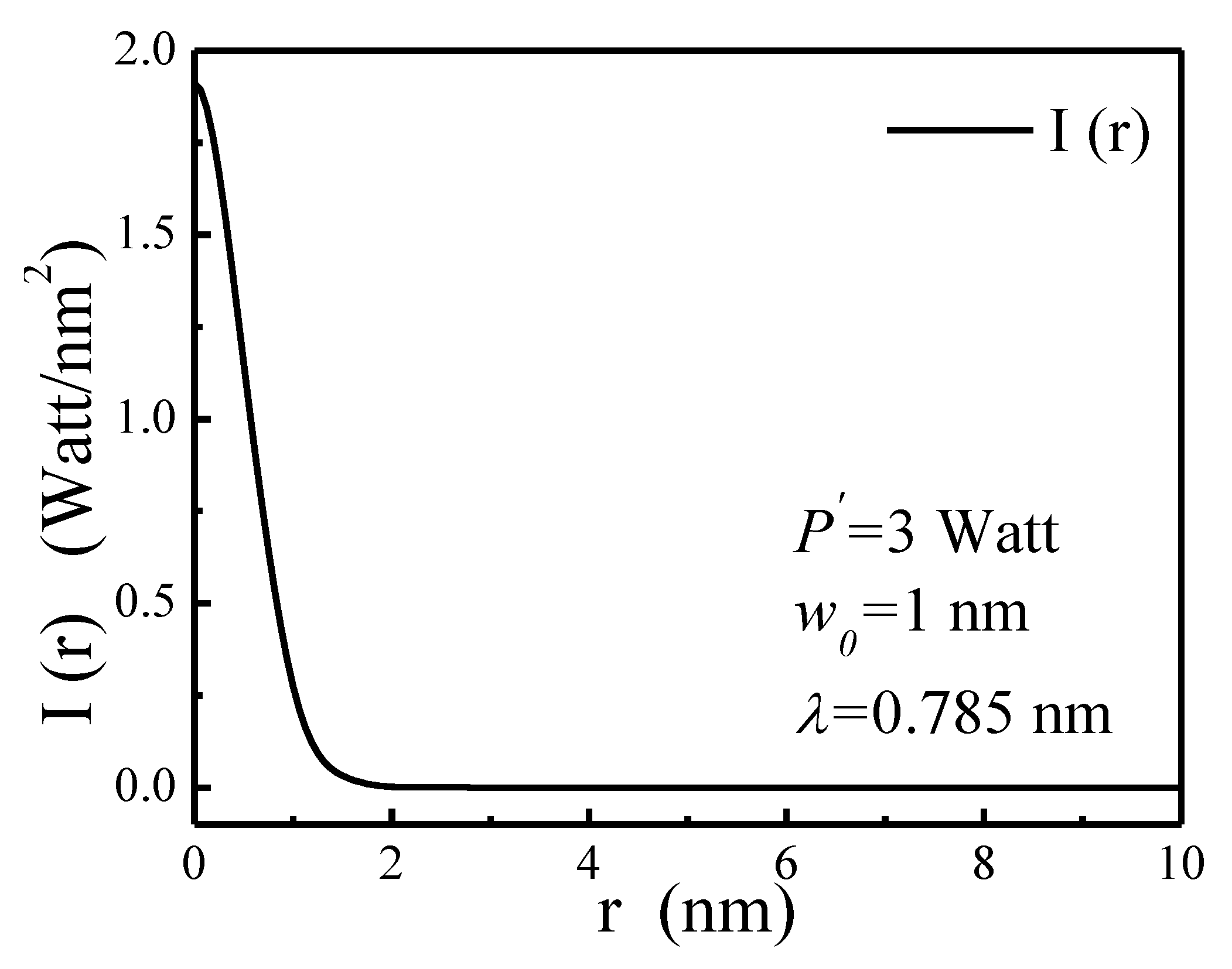
Note that, because of the symmetry considerations, the intensity profile of the crossed laser beam (Equation (6)) is presented in spherical polar coordinates. The graph of I(r) varying with radial distance
r is shown in
Figure 1, where a crossed laser beam of wavelength
λ = 0.785 nm and power
P′ = 3 Watt is focused to 1 nm radius to form a dipole trap. At
r = 0, the intensity is a maximum, and with increasing
r, the intensity is reduced.
Concerning the trapping of an alkali atom using a far-detuned laser beam having wavelength
λ = 0.785 nm, the following points have to be taken into account. As mentioned in the ref. [
39], if we prepare the atoms in the excited state, for instance, F = 2 in Rb, a blue detuned laser beam will create a trappable potential. However, the intensity has to be tuned in such a way that the trap depth is appreciable to hold the atom. Hence, selectively one has to choose the atoms and laser intensity appropriately and prepare them in a specific excited state to achieve optical dipole trapping.
Note that Equation (4) depicts the dipole trap the atom experiences. However, the potential felt by an atomic electron is calculated as
where
q depicts the charge of the electron. Since the local intensity of the optical field is
[
39], the average electric field used in Equation (8) is expressed as
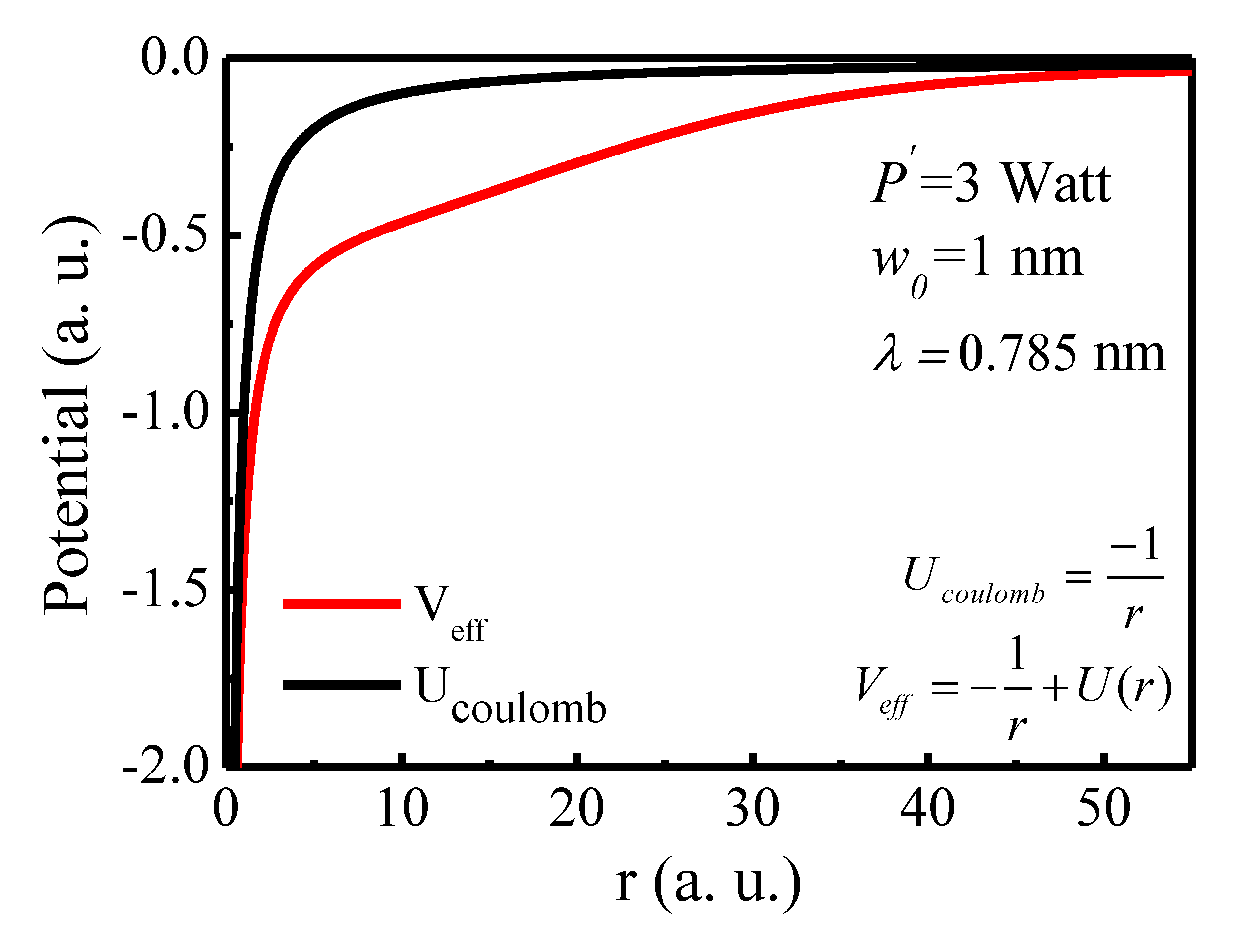
As a model case, the potential experienced by the 1
s electron of the hydrogen atom trapped in the crossed XFEL field (H@XFEL) having wavelength
λ = 0.785 nm (
) is computed when it is focused to
.
Figure 2 shows the effective potential (in a.u.):
, where
U(r) is the potential felt by the atomic electron due to the laser trapping given in Equation (8). Here, the power of the laser beam is taken to be 3 Watts. The plot also compares the pure Coulombic potential of a free H atom:
. One can see that the laser field does alter the depth of the potential. The modification due to the crossed laser beam tends to change the binding energy of the trapped atom.
For a multi-electron system, the potential given in Equation (6) is added to the original Dirac–Hartree–Fock (DHF) equation [
41] and then solved by the equations using the self-consistent method. The modified Dirac–Hartree–Fock (DHF) orbital’s wavefunction
of an
N-electron atomic system in the dipole trap satisfies [
41]
where
is the DHF energy eigenvalue of the
i-th orbital, and
V represents the inter-electron interaction term composed of direct and exchange terms defined as
Thus, the confined atom in the laser field is simulated, and the structural properties can be evaluated. For the present work, the noble gas atoms, such as Ne (Z = 10), Ar (Z = 18), Kr (Z = 36), and Xe (Z = 54), are considered. The corresponding ionization potentials of valence orbitals of Ne, Ar, Kr, and Xe for both free and confined cases are given in
Table 1. One can notice that the laser confinement increases the threshold by roughly a constant amount ~0.39 a. u. This shift in the energy of the ionization threshold is due to the alterations in the depth of the potential.
The DHF wavefunction is considered as the initial state of the target atom, which is photoionized. The dipole-trapped atom is subjected to an external time-dependent external field:
. The modified RRPA equations with the inclusion of laser potential,
, can be obtained from the time-dependent DHF method given as [
38,
42,
43]
where the Lagrangian multipliers
are incorporated to guarantee that the perturbed orbitals
are orthogonal to the occupied orbitals
. The RRPA includes many-electron correlation effects in both the initial and the final states through the terms
in the above equation; all possible two-electron two-hole excitations in the initial state and the interchannel coupling of the final-state channels are accounted for. In the present work, relevant interchannel coupling effects are included in the RRPA for the photoionization of the laser-cooled noble gas atoms. The number of dipole channels coupled in the RRPA is 7 for Ne (channels from the 2p and 2s subshell), 14 for Ar (3p, 3s, 2p, and 2s subshell), 20 for Kr (4p, 4s, 3d, 3p, and 3s subshell), and 20 for Xe (5p, 5s, 4d, 4p, and 4s subshell).
In photoionization, for a particular transition from an initial state
to a final state
, the radial dipole matrix element is given by [
44]
Here,
is the reduced dipole matrix element, and
is the phase shift of the final continuum wavefunction. Since matrix element is generally complex in nature, the phase shift of the photoelectron is defined by
For a dipole transition, indicated by
, the total subshell cross section
is given as [
40,
44]
where
is the dipole transition matrix element present in Equation (13).
The dipole angular distribution asymmetry parameter
βnκ(ω) is given by [
38,
42]
The photoionization time delay of a particular transition is obtained as the energy derivative of the phase of the photoionization complex transition matrix element [
45,
46]. This quantity represents the temporal response of the atomic electron while photoionizing. The average time delay in photoionization of a particular subshell is presented in the current work. It is defined as the sum of the individual channel time delays weighted by the ratio of the respective individual channel cross sections to the total of the cross sections. Hence, the present study computes and analyses the photoionization cross section, angular distribution asymmetry parameters, and the photoionization time delay for both the laser-trapped atom as well as for the free atom. This work focuses on the valance
ns and
np subshells of the noble gas atoms considered.
3. Results and Discussion
In this section, the results for the photoionization cross section, angular distribution asymmetry parameter, and time delay of the valence shells, ns and np, of noble gas atoms (Ne, Ar, Kr, and Xe) trapped by XFEL dipole trap are presented. A comparison of the results for the neutral and that of the A@XFEL is facilitated. As the speed of qubit used in quantum techniques application depends on its interaction time with photon, the photoionization time delay provides a benchmark estimate of the temporal response.
3.1. Neon
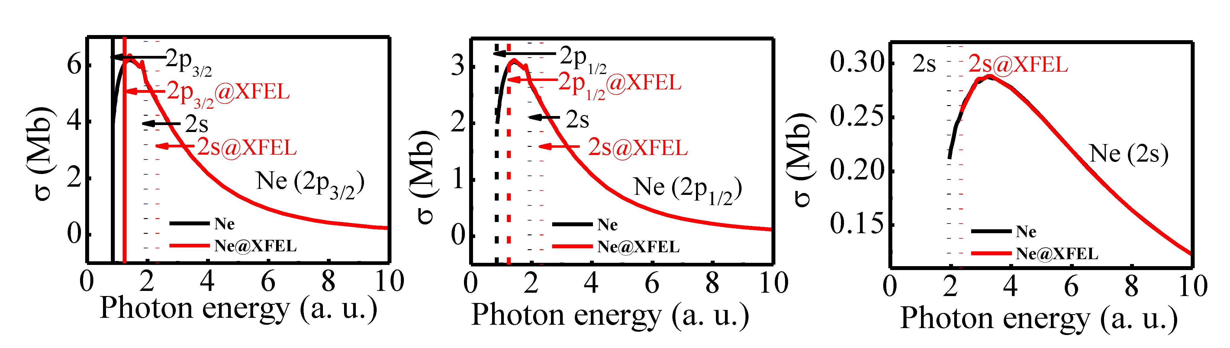
Figure 3 shows the photoionization cross section of the 2
p and the 2
s subshells of the free Ne (solid black) and Ne@XFEL (solid red). For the RRPA, seven dipole channels from the 2
s and 2
p subshells are coupled. The photoionization cross section of 2
s and 2
p subshells of Ne exhibit a shape resonance. Since the Ne atom is less relativistic, results for the spin–orbit split 2
p1/2 and the 2
p3/2 subshells are similar, except for their magnitudes; the ratio of both cross sections indicates the ratio of the number of electrons in the subshells, known as the branching ratio [
44]. For Ne@XFEL, the photoionization thresholds are offset by 0.39 a.u., and, therefore, the onset of photoionization occurs at higher energy. Nevertheless, the Ne@XFEL cross section also exhibits the delayed maximum.
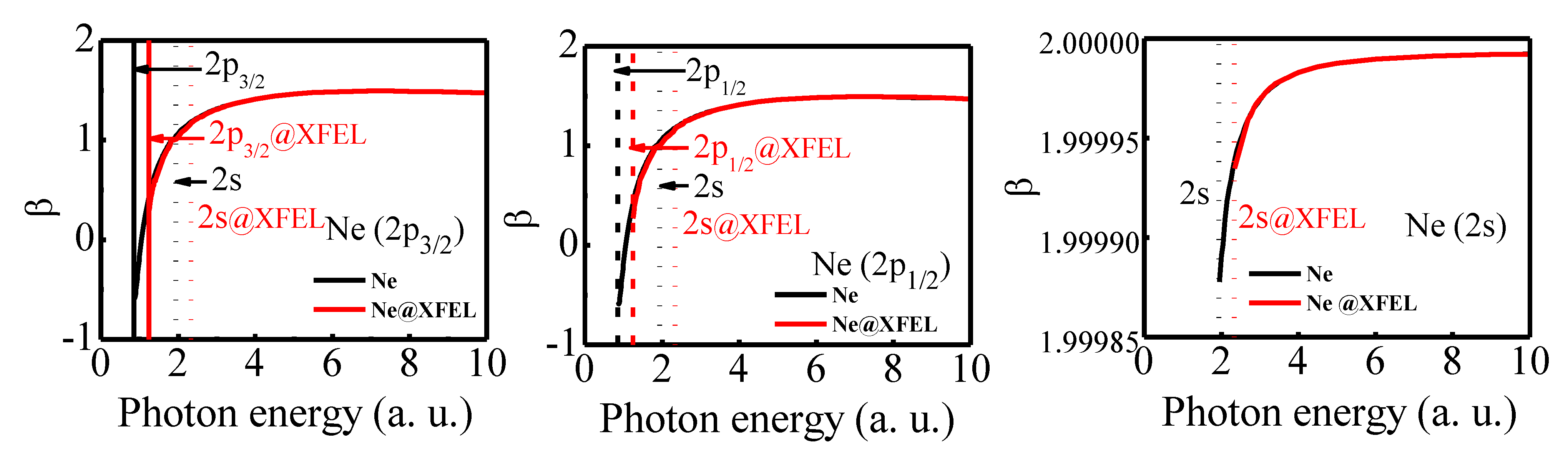
Figure 4 shows the comparison of angular distribution asymmetry parameter
β of the 2
p3/2, 2
p1/2, and 2
s subshells of the free (solid black) and confined Ne (solid red). The figure indicates that apart from the delayed onset of the
β parameter, there is no change induced by the optical dipole trap. This is understandable from the analysis of the cross section. Nevertheless, one may also note that the angular distribution asymmetry parameter has an additional dependence on the relative phase shift of different pair channels (
), as is evident from Equation (16).
Figure 4 indicates that the relative phase shift difference is also unaffected by the laser trapping. One may ask at this juncture whether the relative phase shift of two dipole channels is unaffected by the optical trapping, i.e., will the individual time delay of the dipole channels be altered? A naive answer is ‘possibly not’, as the relative phases are not affected. However, a detailed scrutiny of the individual channel’s time delay requires an affirmative answer.
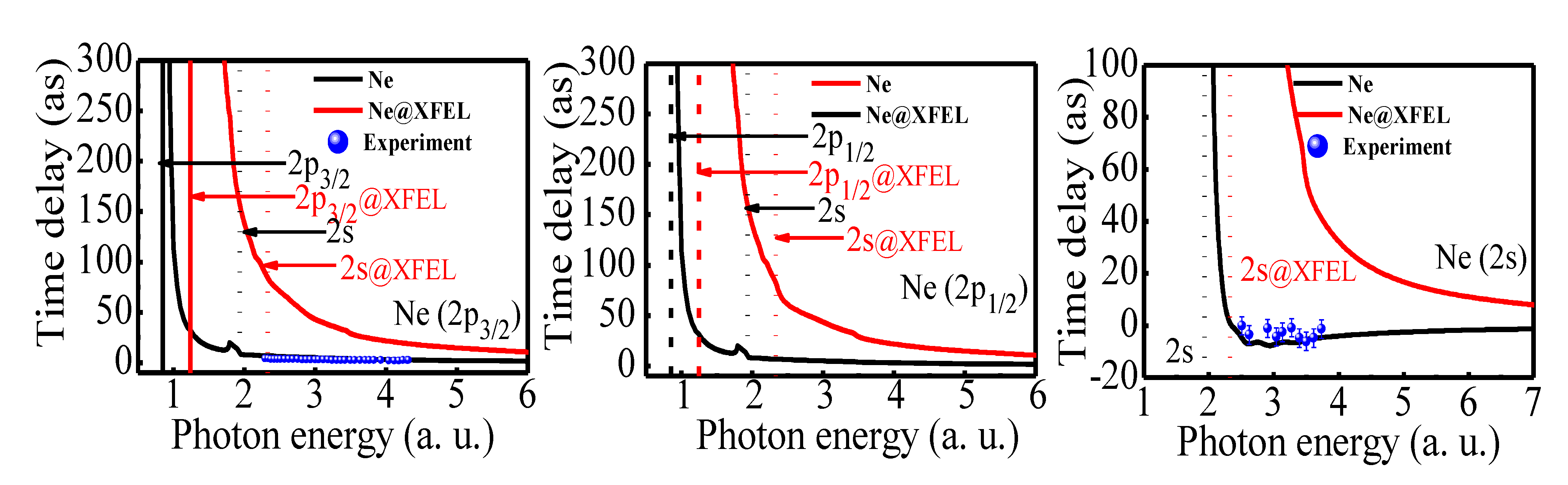
Figure 5 shows the average photoionization time delay from the 2
p3/2, 2
p1/2, and 2
s subshells of Ne. The time delay for the free and confined Ne are quantitatively as well as qualitatively different; the former is larger compared with the latter. For instance, while the time delay in 2
s photoionization is negative and attains a minimum at ~2.5 a.u., the same in Ne@XFEL shows a higher positive value and it does not showcase any symptom of a minimum. A similar quantitative difference is seen in the case of time delay in the 2
p3/2 and 2
p1/2 cases. The additional time delay due to the laser coupling varies from tens of attoseconds to hundreds. Note here that although the relative phase difference is unaltered due to the laser trapping, the phases of the complex transition matrix elements are affected, and it leads to a significantly altered time delay of individual subshell photoionization time delay.
The present results are enriching in two ways. Firstly, the electrons in the atoms in the optical dipole trap suffer more time delay while responding to the external impulse. This observation will have consequences on the performance of such atoms when used in the quantum techniques application. Secondly, the phase shift difference appearing in the angular distribution parameter is unaffected due to the laser coupling, but the individual phase shift on the other hand is altered. This observation asserts that individual channel time delay is more sensitive to the external perturbation compared with the other dynamical variables. A similar remark is made in earlier work on photoionization from Xe [
48].
From an experimental perspective, individual subshell time delay and the relative time delay between 2
p and 2
s photoionization of Ne is measured by several groups [
47,
49]. In the latest experimental attempt, the relative time delay (
τ(2
s)
-τ(2
p)) is directly measured [
47]. In addition, the earlier work obtained Wigner time delay for 2
p subshell to obtain more details about the relative delay difference measurements. Furthermore, the earlier work has obtained 2
s Wigner time delay data by subtracting the
τ(2
p) from
τ(2
s)
-τ(2
p). The left panel of
Figure 5 shows the comparison of time delay for 2
p from the experiment with the present calculation of average time delay for 2
p3/2. Since the Ne is less relativistic, the comparison of the average time delay of the 2
p subshell with that of 2
p3/2 is justified. The comparison shows good agreement between theory and experiment. Similarly, the
2s time delay from the earlier experiment and the present work is also compared, which is shown in the right panel of
Figure 5. The comparison of the 2
s time delay also renders an encouraging comparison, especially in the region of minimum in the time delay. Comparison of theory and experiment encourages us to anticipate that the time delay would be enhanced when probing an atom isolated in a dipole trap.
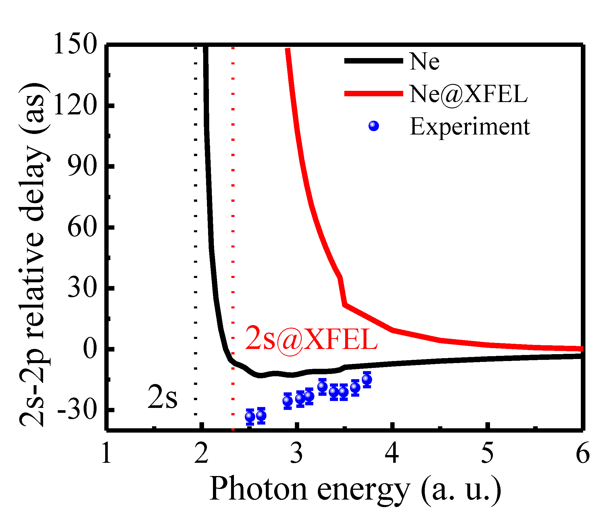
Figure 6 compares the relative time delay difference (
τ(2
s)
-τ(2
p)) of the Ne and Ne@XFEL obtained in the RRPA. The theoretical result is also compared with the available experimental result [
47]. Although the RRPA overestimates the relative time delay compared with the experiment at the minimum, an overall qualitative agreement is found. Of course, the Ne@XFEL has enhanced delay difference, as is evident from the figure. As photon energy increases, the time delay difference between free and confined Ne vanishes. This is true even in the case of individual channel time delays. This is understandable, as the highly energetic photoelectron does not see the details of the confinement potential, and, therefore, the Ne and @Ne time delay is more or less the same.
3.2. Argon
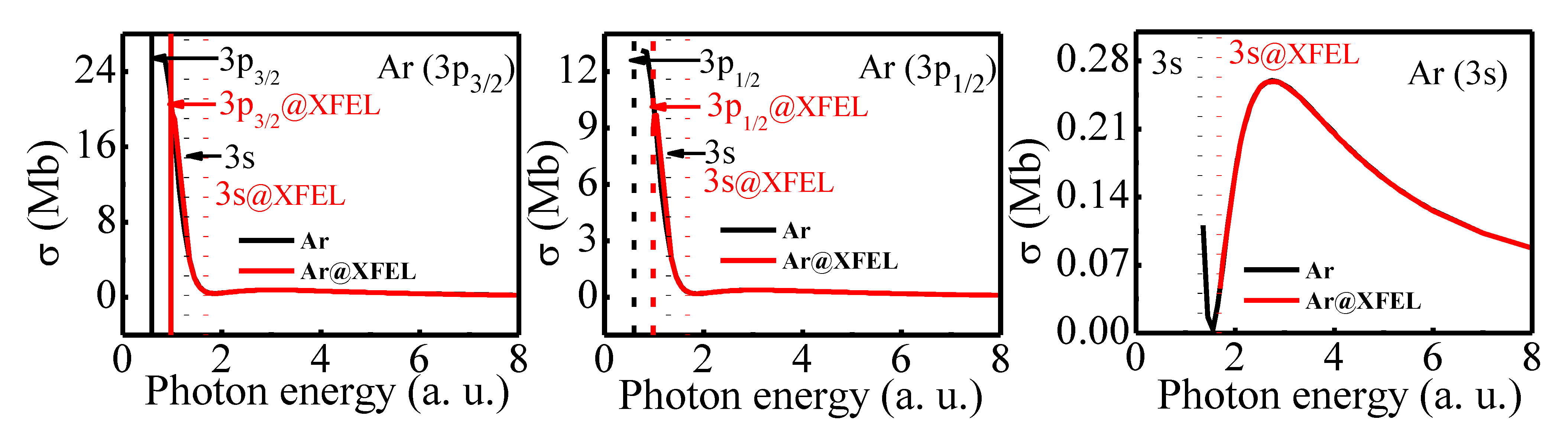
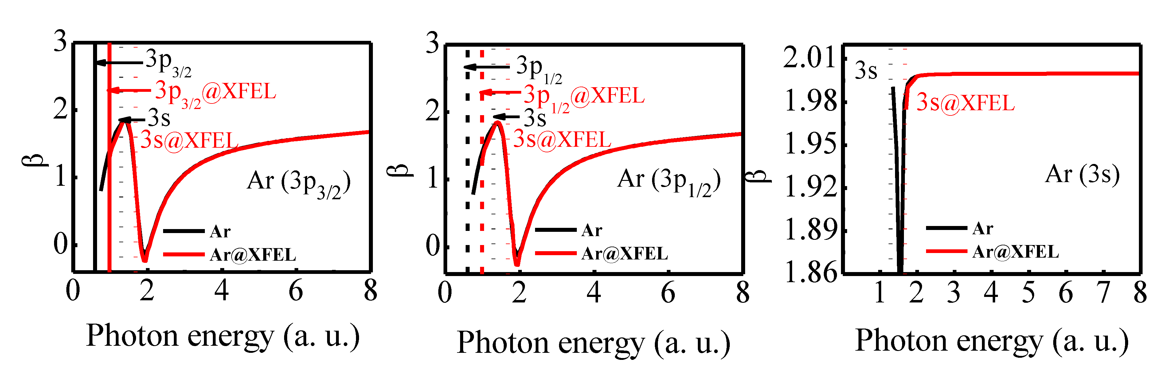
Figure 7 and
Figure 8 show the photoioinization cross section and angular distribution asymmetry parameters of spin–orbit split valence subshells of Ar and Ar@XFEL. Since Ar is less relativistic, the 3
p3/2 and the 3
p1/2 subshells exhibit similar photoionization features. The 3
p cross section drops from a high value, as there is a shape resonance. At ~1.85 a.u., the 3
p → εd dipole channels undergo a Cooper minimum. Likewise, the 3
s subshell cross section also exhibits a Cooper minimum at 1.55 a.u. Note that the Cooper minimum in the 3
s photoionization channel in the 1.5 a.u. region arises solely due to interchannel coupling with the 3p photoionization channels [
50]. The angular distribution asymmetry parameter has additional dependence on the relative phase shift of different photoionizing channels. The
β3p rises to a maximum value at 1.35 a.u. and displays a minimum at 1.85 a.u. Note that the minimum in the
β3p occurs at the location of the Cooper minimum. In the 3
s case, because of the Cooper minimum, there is a dip in the
β; the deviation of
β from 2.00 in the n
s case shows the impact of the relativistic effect on the CM in the spin–orbit split subshell channels. The reliability of the RRPA results are well established through a comparison with experimental results.
In the case of Ar@XFEL, as already discussed, the subshell thresholds are offset by 0.39 a.u. One can see from
Figure 7 and
Figure 8 that the photoionization cross section and angular distribution asymmetry parameters follow the same profile of the free Ar atom case, except for the shift in the threshold. The 3
p cross section has the Cooper minimum at the same location as in the free Ar case. However, in the case of the 3
s subshell, the Cooper minimum is in the discrete region below the threshold. Therefore, the Cooper minimum is not present in the 3
s cross section. Accordingly, the dip in the
β is also not present in the 3
s angular distribution asymmetry parameter.
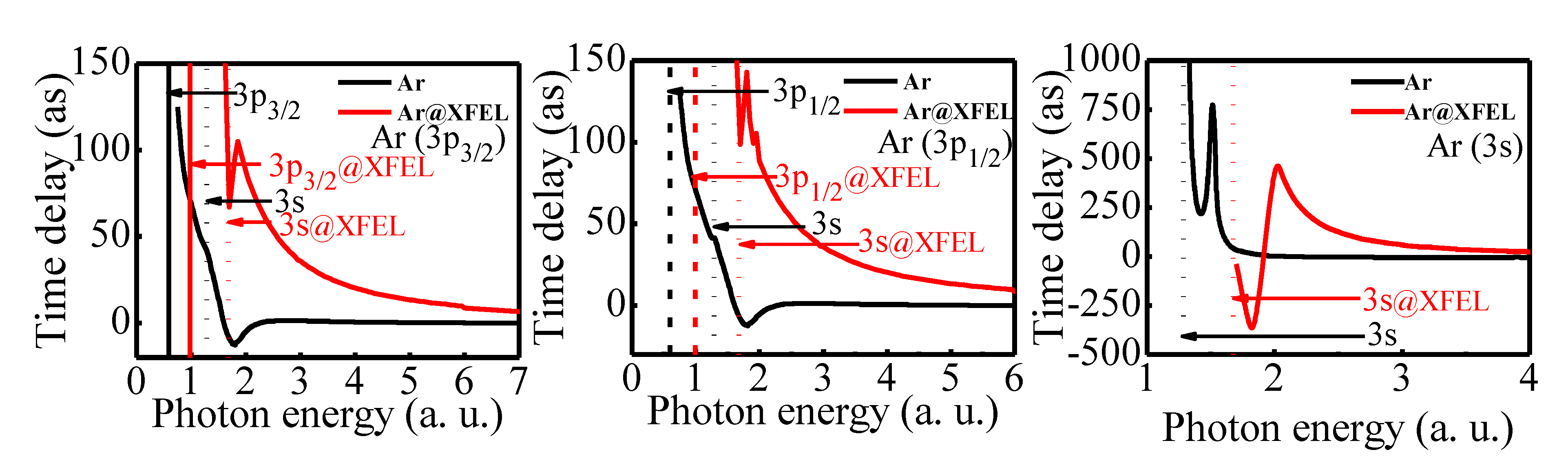
The average time delay (τ) of 3
p3/2, 3
p1/2, and 3
s subshell photoionization of Ar and Ar@XFEL is shown in
Figure 9. Cooper minima in the
p → εd transition matrix element are exhibited as a −
π jump in the phase shift, which results in a sharp and deeper negative time delay at approximately 1.805 a.u. in the individual spin–orbit split
p → εd channels of free Ar. The
p → εs channels do not have the Cooper minimum; therefore, the time delay of these channels decreases from a positive value smoothly for neutral Ar. The trend of the average time delay of 3
p subshells of the free Ar follows that of the 3
p → εd channels as its matrix element is dominant except in the CM region; at the CM, the 3
p → εs channel time delay dominates. As a result, the average time delay of 3
p1/2 and 3
p3/2 subshells exhibit a competition between that of the
p → εd and
p → εs channels. Hence, the average 3
p3/2 and 3
p1/2 time delay shown, respectively, in
Figure 9 left and middle panel is wider and less deep compared with the individual time delays in the region of Cooper minima due to the contribution from the 3
p → εs channels. The average time delay of 3
p1/2 and 3
p3/2 subshell exhibit, respectively, a minimum at 1.805 a.u. and 1.82 a.u. of photon energies, which corresponds to the Cooper minimum. The Cooper minimum in the 3
s → εp channels induces a +
π jump in the phase shift, which is translated as a positive peak in the individual channel time delay of the free Ar atom. Upon averaging, the peak widens and results in a maximum at 1.51 a.u. The results for free Ar atoms have been discussed in great detail using RRPA and other theories earlier [
51,
52].
In quite a contrast to the free Ar case, the photoionization time delay in the Ar@XFEL is widely different. Firstly, the Ar atom in the optical dipole trap experiences a larger time delay compared with the free case. Although the Cooper minimum is present in the 3
p cross section of Ar@XFEL, the features of the Cooper minimum are overshadowed by the confinement effects. As discussed in the free Ar case, the average time delay of 3
p1/2 and 3
p3/2 also follows the competition between individual
p → εd and
p → εs channels in the Ar@XFEL case. However, the
p → εs channel time delay is considerably larger in the Ar@XFEL case at the CM compared with the free Ar case. Therefore, the CM features are visible in the 3
p time delay as a kink near CM. For instance, the time delay of 3
p3/2 (left panel of
Figure 9) and 3
p1/2 (middle panel of
Figure 9) subshell of Ar@XFEL shows a bump at 1.7 a.u.. The variation of the time delay in 3
p1/2 and 3
p3/2 subshell photoionization illustrates the importance of relativistic effects.
Concerning the 3s case, as the CM in the 3s → εp channels is moved to the discrete and, therefore, is absent in the continuum energy range in the Ar@XFEL case, the peak in the time delay is missing. Rather, it decreases to a negative minimum and then becomes positive. Further, the 3s time delay decreases from a high positive time delay. Note that the time delay in photoionization from the Ar@XFEL is, in general, large compared with that of free Argon.
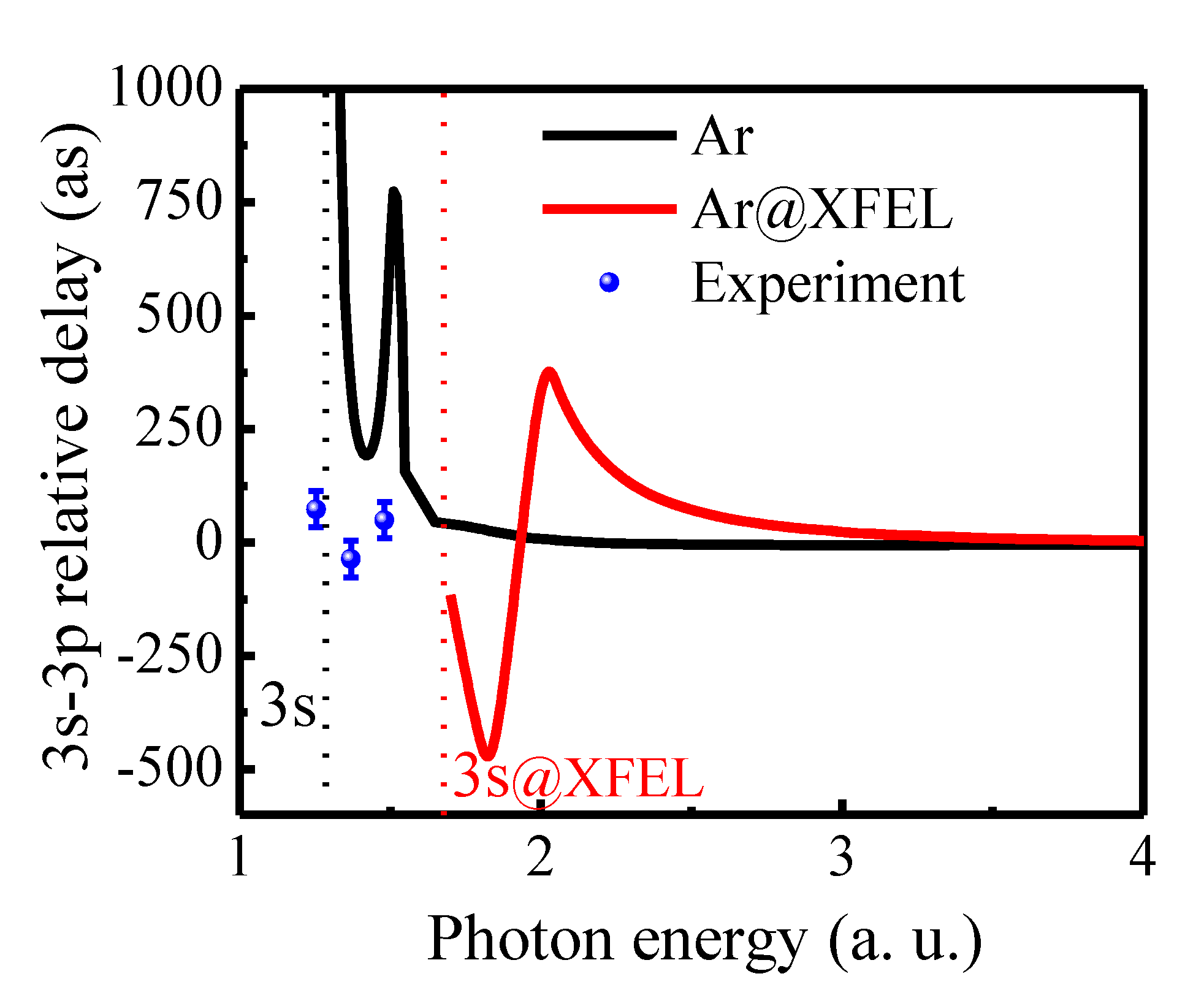
It is to be asserted that the cross section and angular distribution are unaltered due to the dipole trapping, except for the shifting of the threshold. However, the individual phase shift and the time delay are modified due to the laser confinement. At this point, it is important to check and verify whether the time delay differences are altered due to trapping the atom. Because the time delay differences can be measured [
52],
Figure 10 presents the time delay difference between 3
s and 3
p photoelectrons in free and confined Ar. Experimental results of relative time delay (
τ(3
s)
-τ(3
p)) are included for comparison [
53]. From the experimental work, the time delay for the single-photon ionization channel is plotted. There is a good qualitative agreement between RRPA and experimental data; the minimum in the relative time delay is in good agreement, although the magnitude is different. While the 3
p electron time delay dominates over 3
s electrons at higher energy value, near the 3
s threshold, the 3
s electrons escape more slowly compared with the 3
p electrons in the case of free Ar case. In the Ar@XFEL case, the time delay difference is modified due to the laser trapping. The peak in the time delay difference is missing due to the absence of the Cooper minimum in the 3
s subshell channels.
3.3. Krypton
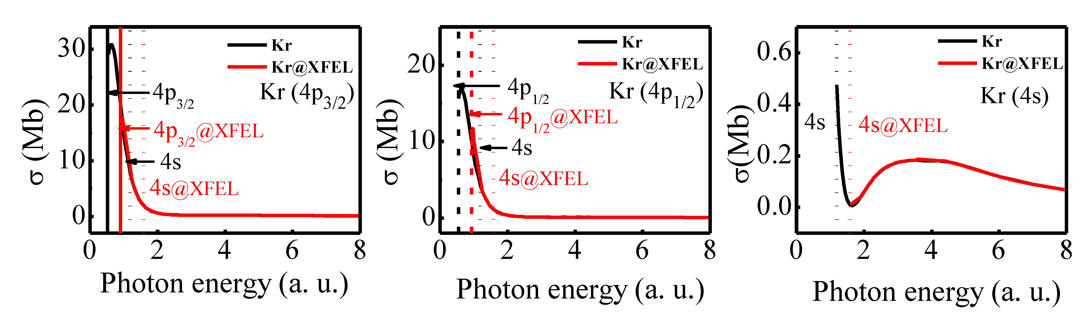
We display the partial photoionization cross section of the 4
p3/2, 4
p1/2, and 4
s subshells of Kr calculated in RRPA in
Figure 11. A comparison between free Kr and Kr@XFEL is also rendered in
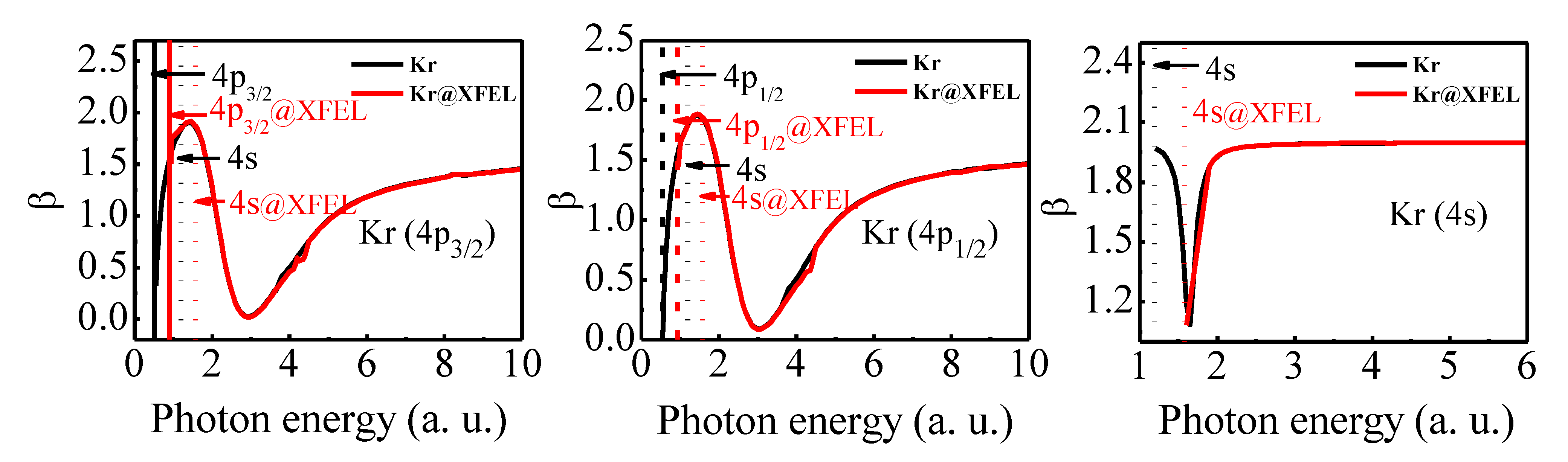
Figure 11. A similar comparison for the angular distribution asymmetry parameter
β of the 4
p3/2, 4
p1/2, and 4
s subshells is given in
Figure 12. The 4
p subshell cross section of the free Kr displays a shape resonance at the threshold, and the
σ drops from the threshold. The 4
s subshell cross section exhibits a Cooper minimum at 1.65 a.u., which is due to the correlation effects [
54]. The inclusion of correlation effects using RRPA has demonstrated excellent agreement with experimental results [
52]. Considering the Kr@XFEL case, since the thresholds for the 4
p and 4
s are shifted in the confined case, the cross section has a different onset in the RRPA case, as shown in
Figure 11. Because of this, the Cooper minimum in the 4
s cross section is absent in the Kr@XFEL case, rather the cross section appears to recover from the CM at the threshold. This will have implications in the angular distribution asymmetry parameter as well. From
Figure 12, one can see that the 4
p3/2 and 4
p1/2 angular distribution asymmetry parameter of Kr@XFEL agrees with that of free Kr, except for the shift in the threshold. In the 4
s case, the free Kr exhibits a dip in the
β at the CM location. However, in the Kr@XFEL case, the
β4s increases from the threshold and reaches the non-relativistic value of 2. Since the CM in the 4
s subshell is below the threshold in the confined case, the dip in the angular distribution parameter is missing.
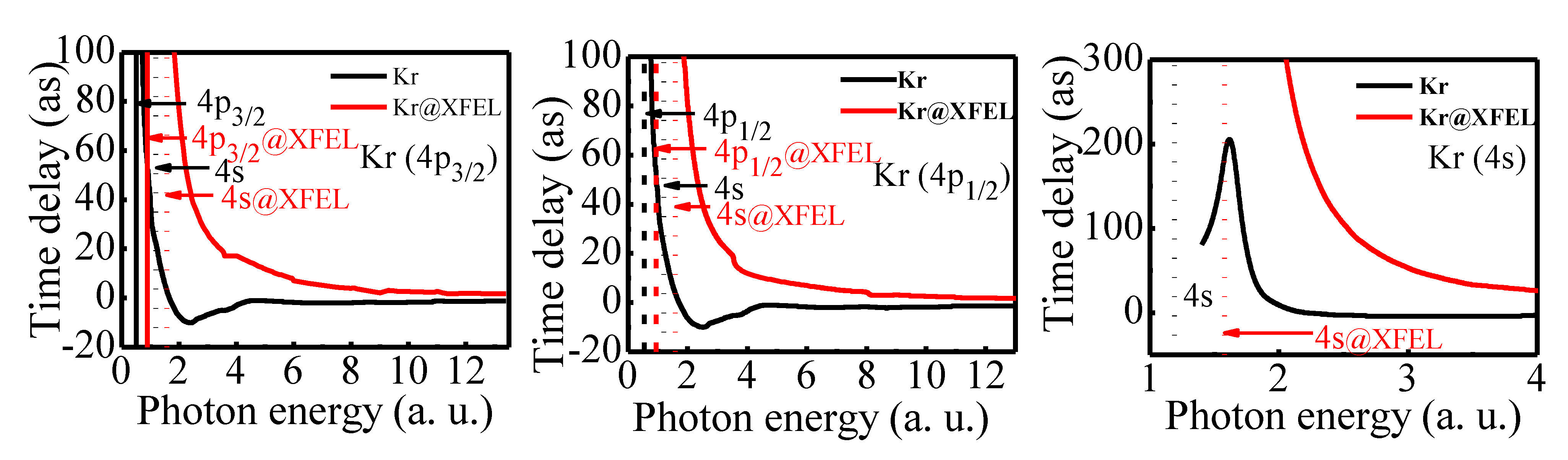
The average time delay of the 4
p3/2, 4
p1/2, and the 4
s subshells of the Kr and Kr@XFEL are shown in
Figure 13. The individual channel time delays are qualitatively and quantitatively different in the two cases; the Kr@XFEL shows a larger time delay consistently in all cases. At the CM, the 4
p subshells exhibit a minimum time delay in the free Kr case. The CM features are shadowed in the Kr@XFEL case; the atom in the dipole trapping shows enhanced time delay in the entire region. The alterations in the time delay due to the laser trapping follow a trend similar to that of the Ar case.
The induced Cooper minimum in the 4s subshell cross section manifests as a peak in the corresponding subshell’s time delay. As in the 4p cases, the confinement vanishes the features of the Cooper minimum in the time delay, as the CM is absent in the Kr@XFEL case.
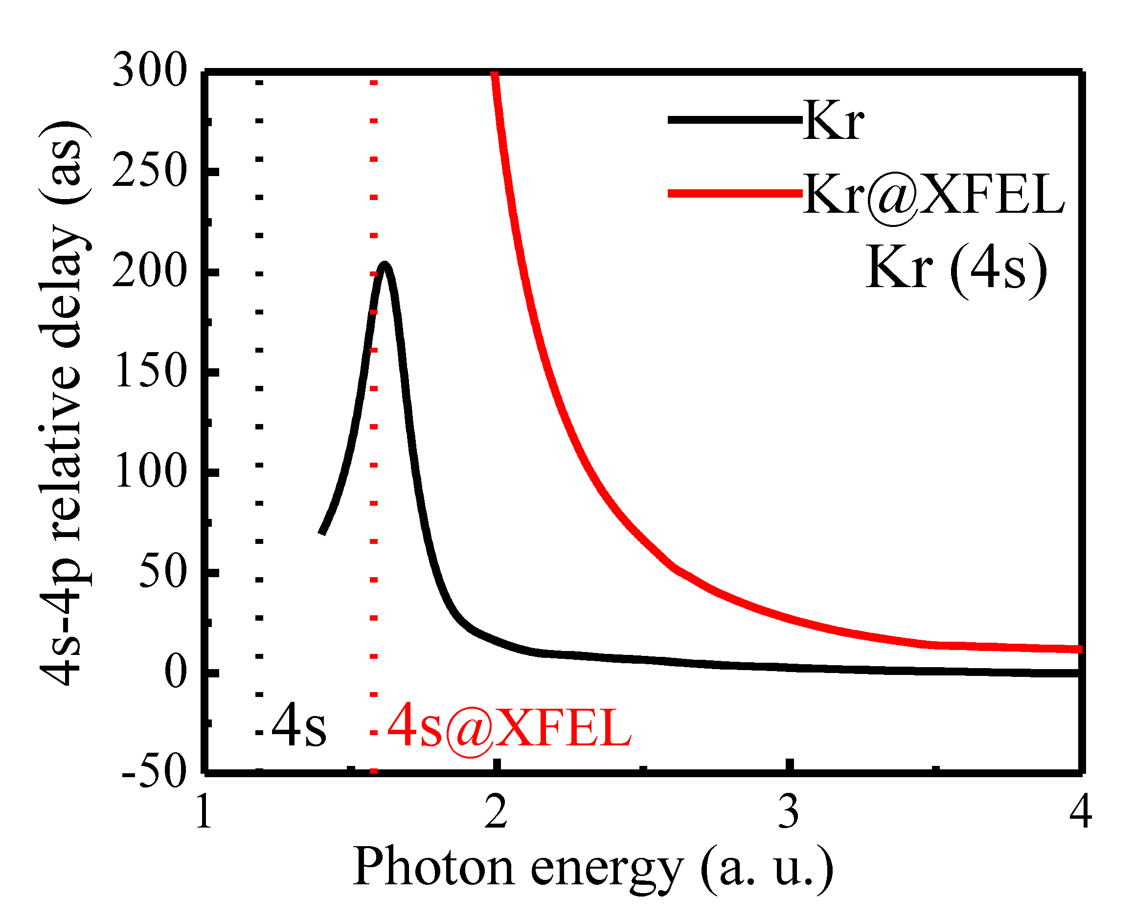
Figure 14 shows the difference between 4
s and 4
p subshells’ time delay in the free and confined cases. Although experimental data on photoionization time delay in Kr are not available for comparison, we provide theoretical results for completion and as a reference for experimentalists.
Figure 14 shows that the 4
s electron takes a longer time than 4
p electrons near the 4
s threshold of the free Kr. Due to the effect of 4
s CM, the relative time delay is a maximum. The confinement modifies the time delay difference; the relative time delay attains a maximum near the 4
s threshold, and it decreases monotonically.
Similar to the other noble gas atoms, Kr also exhibits differences in the time delay due to the dipole trapping. At the same time, the dipole cross section and angular distribution asymmetry parameters are more or less the same except for the shift in the threshold. The current observations reassert the observation in the ref. [
55] that time delay is more susceptible to external perturbations compared with the angular distribution of the photoelectrons.
3.4. Xenon
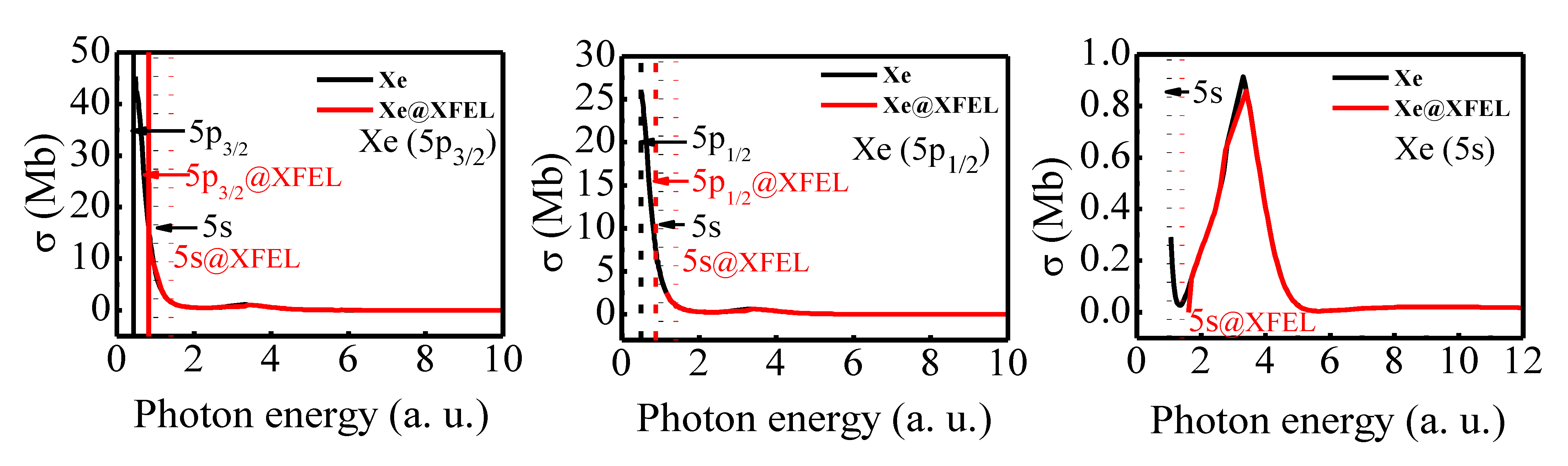
Figure 15 and
Figure 16 show, respectively, the photoionization cross section and angular distribution asymmetry parameter of the 5
p3/2, 5
p1/2, and the 5
s subshells of Xenon. The 5
p3/2 and the 5
p1/2 cross section of the free Xe exhibit a Cooper minimum at approximately 2.3 a.u. Further, there is a second Cooper minimum, which is at relatively higher energies, at 5.7 a.u. In the 5
s case of free Xe also, two Cooper minima are, respectively, observed at photon energy 1.3 a.u. and 5.65 a.u. It has been observed that the effects of coupling with the 4
d photoionization channels are quite important in the region of both Cooper minima. It is also established that the second Cooper minima in Xe valance subshells are due to the interchannel coupling correlation effects. Considering the Xe@XFEL case, the 5
p subshell exhibits delayed onset of cross section due to the shifting of the threshold. Likewise, in the 5
s case, the first Cooper minimum is absent in the confined Xe case. Apart from the shift in the threshold, the cross section profiles of the Xe@XFEL are qualitatively and quantitatively the same as that of the free one.
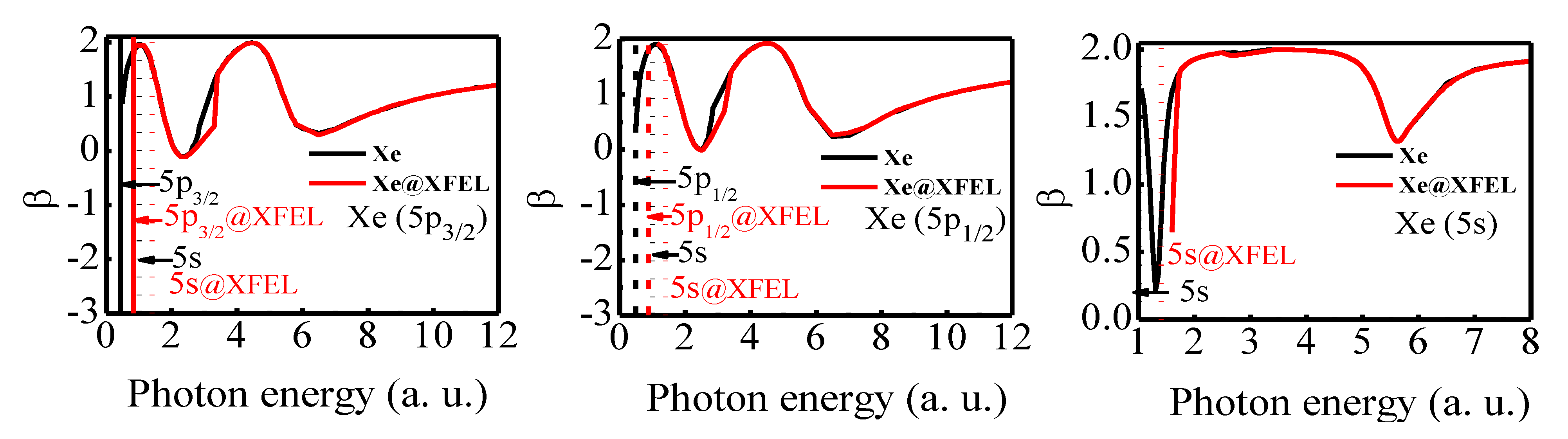
The 5
p and 5
s angular distribution asymmetry parameters for free and confined Xe are shown in
Figure 16. The
β is dependent on the ratio of the magnitudes of the matrix elements of the relativistic dipole channels along with their relative phases. From
Figure 16 left and middle panel, the comparison of 5
p β of free Xe and Xe@XFEL suggests no dramatic modification due to laser trapping, except for the shift in the threshold. Corresponding to the Cooper minima in the cross section, a dip in the
β is obtained. Since the CM is present in both cases in 5
p, the features of the angular distribution are alike. However, the 5
s case is remarkably different. Since the first Cooper minimum is missing in the Xe@XFEL case, the
β5s appears to rise from the minimum at the threshold. The additional dip at 5.65 a.u. is due to the CM at that location.
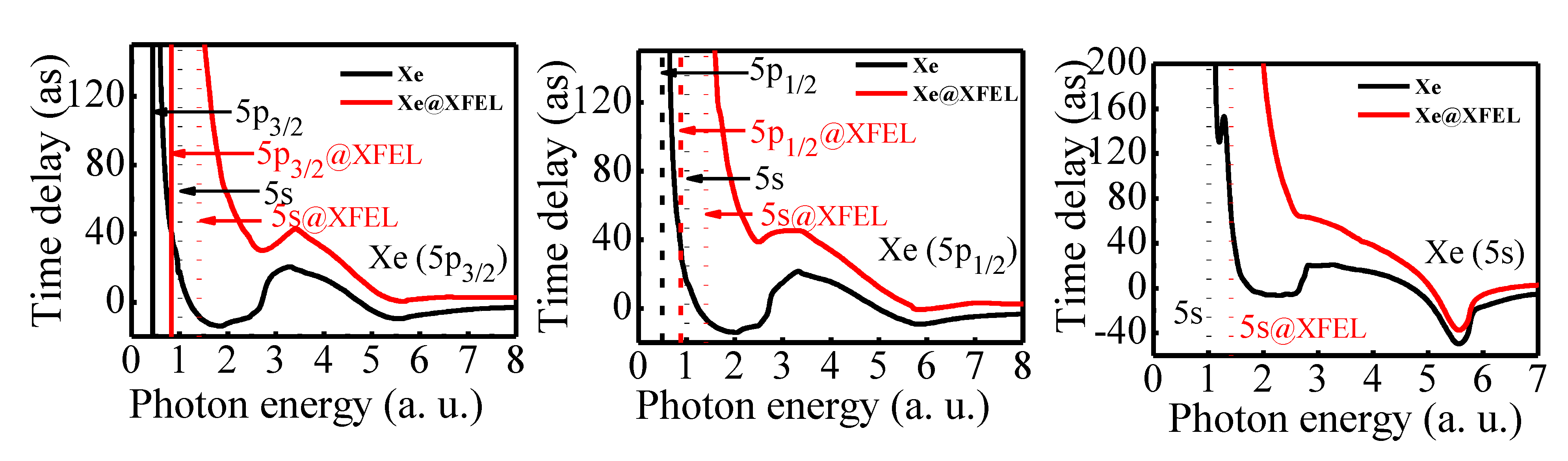
A set of corresponding figures of the time delay (τ) is shown in
Figure 17. Two dips in the 5
p photoionization time delay of free Xe correspond to a -
π jump in the phase shift at the Cooper minimum. Note that the inclusion of the dipole trap reserves the qualitative nature of the 5
p time delay, although a quantitative shift has occurred. In the 5
s case also, there is a qualitative similarity between the time delay of the photoionization from the free and confined Xe. Since the CM occurs below the threshold for the 5
s subshell of Xe @XFEL, the first dip in the time delay is present only as a kink. Apart from the shift in the threshold, there is a dramatic change in the individual channel phase shift and, therefore, in the time delay also.
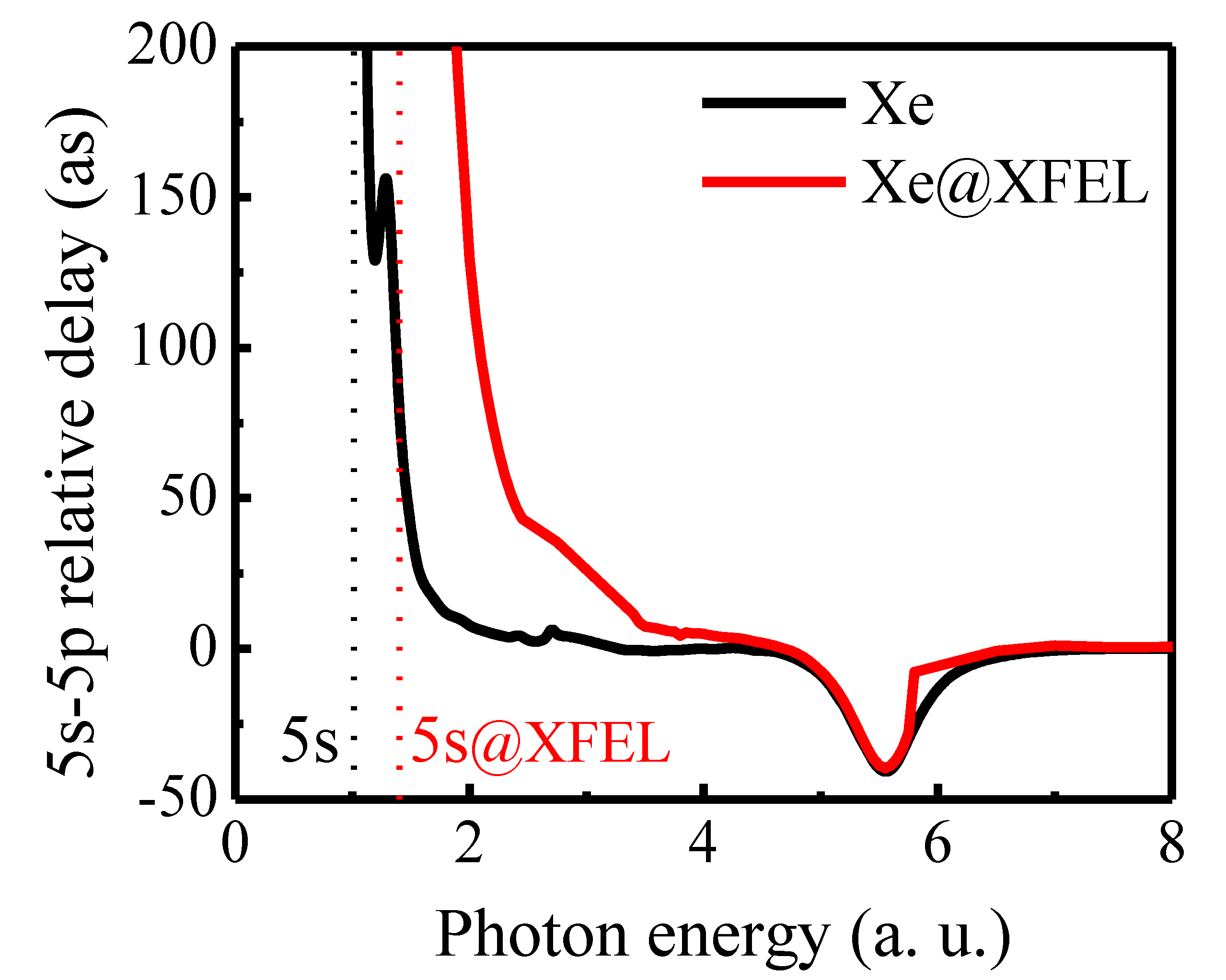
Figure 18 shows the time delay difference between the 5
s and 5
p subshell photoionization. The relative time delay difference is enhanced upon crossed laser beam confinement, which is evident from
Figure 18. Due to the presence of CM, there is a dip in the time delay difference at the location of the second Cooper minimum of the 5s and 5
p subshells. As the photon energy increases, the difference between both the free and confined time delay difference is reduced.
The current set of results on the noble gas atoms hints that the interaction time of the dipole-trapped atom is noticeably modified compared with that of the free atoms. For applications in the quantum information side, a pump laser is made to interact with a trapped atom. In the context of a two-level system, Rabi frequency is defined as where is the atomic dipole moment, and is the electric field of the pump laser. The speed of such a quantum device (quantum readout time) depends on the Rabi frequency of the pump laser. In other words, Rabi frequency gives the electronic transition rate between the two levels considered. Since we interpret the interaction time scale of the atom (qubit) as the readout time, the speed of the quantum device depends on the Rabi frequency. Hence, the present investigation serves as a primer roadmap to assess the speed of quantum devices.


