
Interaction of Electrons and Positrons with Protons Aligned in One-Dimension Line

1
Institute for Nuclear Research, ATOMKI, 4026 Debrecen, Hungary
2
Doctoral School of Physics, University of Debrecen, Egyetem tér 1., 4032 Debrecen, Hungary
*
Author to whom correspondence should be addressed.
Atoms 2023, 11(3), 46; https://doi.org/10.3390/atoms11030046
Submission received: 7 December 2022
/
Revised: 16 February 2023
/
Accepted: 24 February 2023
/
Published: 3 March 2023
(This article belongs to the Special Issue Interaction of Electrons with Atoms, Molecules and Surfaces)
Abstract
:We present theoretical studies of electron and positron interaction with protons aligned in a one-dimension periodic line. The equally spaced protons were artificially generated where the individual protons are fixed in a certain position. The incident energies were 500 eV and 1000 eV. The electron and positron trajectories passing through these periodic multiple scattering objects were calculated using a classical trajectory Monte Carlo method. We show that this proton configuration has focusing and defocusing properties depending on the certain initial conditions.
1. Introduction
Electron and positron scattering are of great importance to understand the collision dynamics involving atomic [1,2] and molecular [3,4] targets. Furthermore, electron and positron scattering are important for applications in various fields of physics depending on the type of the target and the projectile energies, for example, in chemical, biological, plasma and laser physics, and astrophysics [5,6].
The cusp-like peak in the energy spectrum of electrons in the direction of the projectile (0°) emitted in ion–atom collisions was first observed by Crooks and Rudd in 1970 [7]. Since the first observation, the ECC (electron capture to the continuum), although re-cently we can say it is a trivial process and we can easily understand, studies had been a vital part of the atomic collision physics in that time. This process is a special case of ionization, when the ionized electron is strongly influenced by the projectile due to the small difference between their velocities. The aim of the investigations was to understand the dynamics of colliding atomic systems. The most important dynamic mechanism for the appearance of the ECC peak is the focusing of the ejected target electrons in the forward direction of the outgoing projectile, due to the attractive interaction between them. For charged projectiles, the ECC cusp is the result of the long-range Coulomb interaction between the projectile and the ejected electron. We can have cusp and anti-cusp-like structures depending on the projectile charge. Although during the year’s number of work investigated the phenomena with heavy ions [8,9,10,11], light projectiles, using positive [12,13] or negative charged particles [14] and even neutral ones [15], it may hold interesting observations [16,17]. In connection with the ECC studies, we apply here a special target, namely protons aligned in a one-dimension line. We note that the recent study is not one-by-one mapping of the idea and subject of the previous studies. The aim of the present work is to understand the dynamics involving interaction of projectiles and one-dimensional material. We present theoretical studies of electron and positron interaction with protons aligned in a one-dimension periodic line. The individual protons are located at fixed positions with equidistant separation. The incident energies were 500 eV and 1000 eV. In our simulations we used the classical trajectory Monte Carlo (CTMC) method. It is well known that the CTMC method can treat the many-body problem successfully. The CTMC method is a non-perturbative method, where classical equations of motions are solved numerically [18,19], and it is useful in treating atomic collisions where the quantum mechanics become complicated [20]. CTMC can handle calculations applied in atomic collisions involving three or more particles [21,22]. The CTMC method described reasonably well single and double ionisation [23,24,25,26,27], excitation [28], electron capture [19,29] and scattering channels [30,31].
The purpose of our present work is twofold. First, the results obtained from these model calculations will help us to further study more complicated systems such as two-dimensional materials like graphene. In this case, we consider a suitable configuration for our 1D material while using appropriate separation between the constitutes elements. Second, these calculations also help us to classically mimic the same structure like that produced by the interference effect. The double slit experiment of Thomas Young is one of the most famous experiments in physics showing the wave behaviour of particles [32]. Murray et al. [33] experimentally and theoretically studied the (e, 2e) collision in diatomic molecules ( and ), searching for Young’s double slit-type interference. Murray et al. suggested a simple model that considered that each constituent atom acts like an individual slit in the optical analogy. In our work, we consider the cases: double slits (two protons) and multiple slits (ten protons). Atomic units are used throughout the paper unless otherwise indicated.
2. Theory
In the present work, our artificial hypothetical system consists of fixed protons and either electrons or positrons as projectiles. The ionisation and excitation channels are not existing due to the absence of electrons in the target structure. There is a small probability for electron capture channel for electron impact, but the probability can be decreased to a negligible amount by using high kinetic energy for the projectiles, and by increasing the number of protons in which the attractive coulomb potential from the other (N-1) protons prevent the electron capture by a certain proton. We note further that the reason for using positrons as projectiles was to completely neglect the electron capture channel. However, we kept the electrons as projectiles since experimentally there are some difficulties with positron sources [34,35,36].
During our simulations we applied the classical trajectory Monte Carlo (CTMC) method for our many-body problems. The trajectories of the projectiles with different initial conditions are calculated in three different target systems, i.e., a system consisting of one proton, and two other systems consisting of two and ten protons.
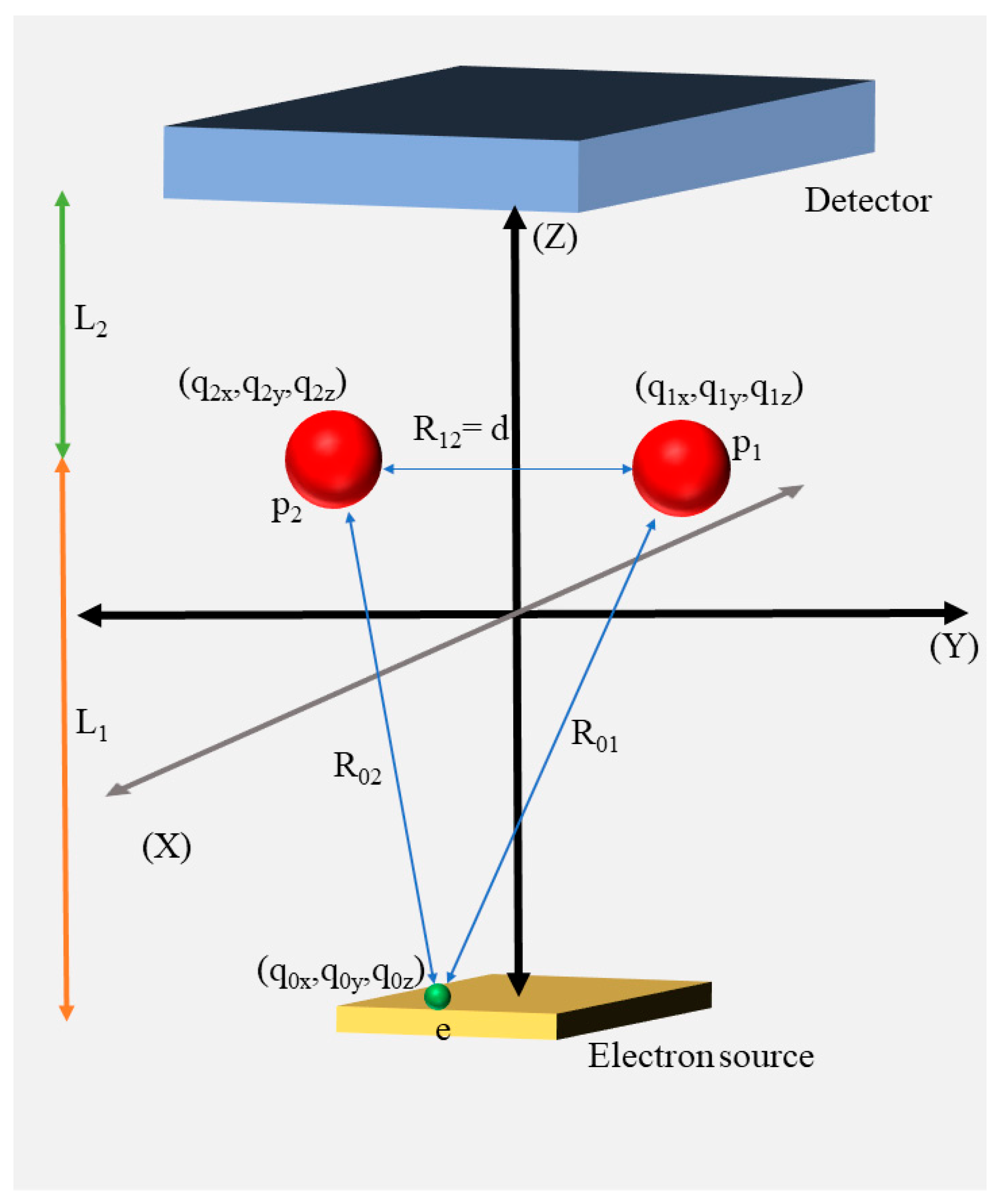
Since the protons are considered to be fixed, this means that only the projectiles will have kinetic energy. We take into account Coulomb interactions between the protons and the projectiles. The corresponding coordinates and momenta of the particles are described by the vectors qi = (qix, qiy, qiz) and pi = (pix, piy, piz). Figure 1 shows the schematic diagram of a two-proton system in colliding with electron projectiles.
The Hamiltonian equation for N fixed protons and a projectile can be written as:
where the projectile mass, charge and momentum are labelled by , and , respectively, and the ith proton charge is labelled by .
The associated canonical equations of motion are:
Finally, we have six coupled equations of motion, which are given by:
The 4th order Runge–Kutta method is employed to numerically solve the equations of motion (see Equations (4)–(7)) for a large number of trajectories with randomly generated initial xy-positions () of the projectiles. The equations of motion are solved individually for each trajectory. The kinetic energies of the projectiles are taken to be 500 eV and 1000 eV. At the beginning of the simulation, the projectiles have non-zero vz velocities according to the initial energy. The vx and vy were set to be 0.
3. Results and Discussion
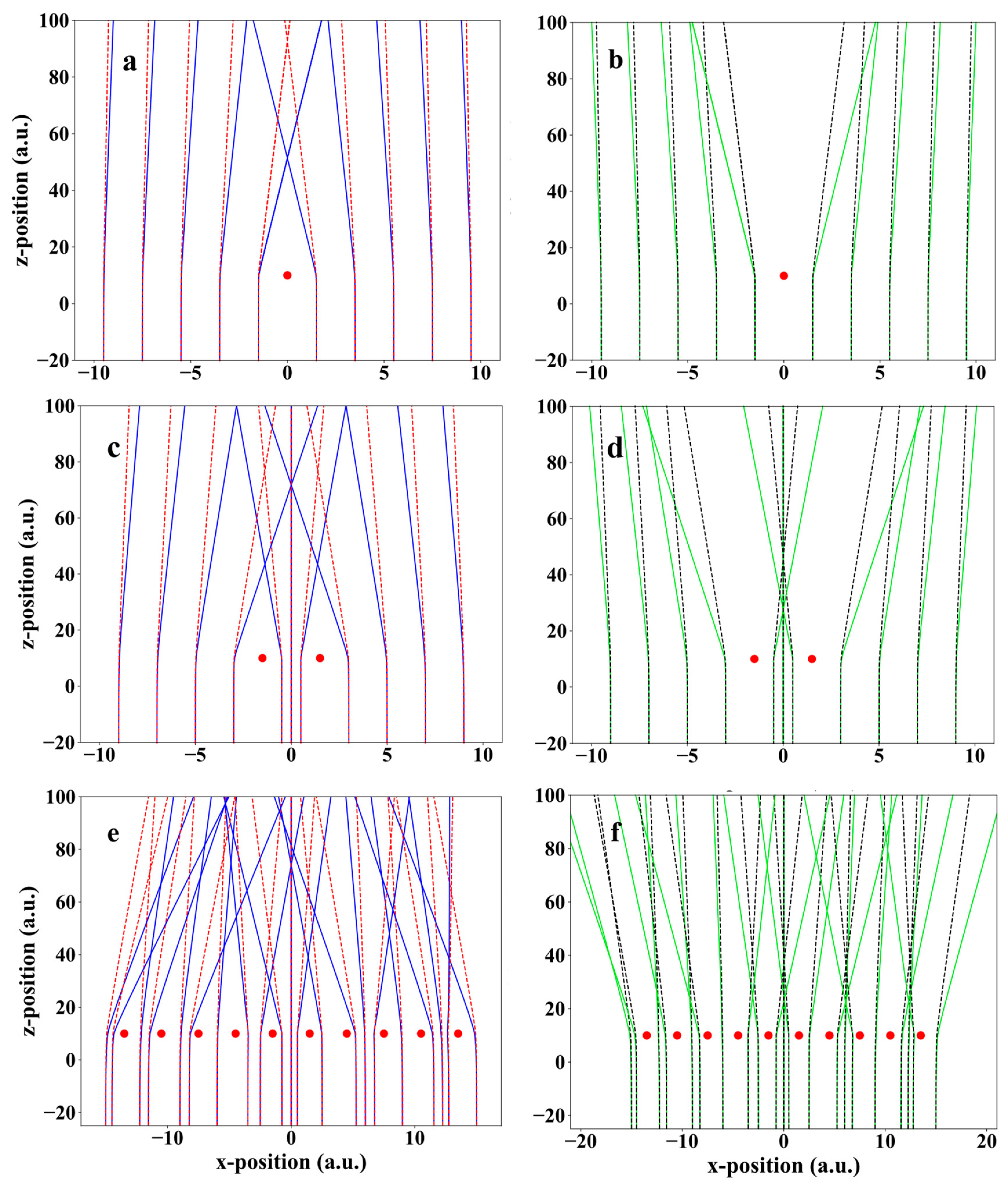
For the three configurations of protons, calculations were performed for large numbers of classical trajectories (i.e., electrons and positrons) having collision energies of 500 eV and 1000 eV. The protons are fixed at certain coordinates as follow, for one proton [], for two protons [ and ] and for ten protons [ and , ]. From Figure 2, we can clearly see that the deflection angle of the projectile depends on many parameters: the kinetic energy of the projectiles, the impact parameter, the number of protons (i.e., total charge) and the charge of the projectile. The first two parameters are inversely proportional to the deflection angle, while the third parameter is directly proportional to the deflection angle. Electrons and positrons under similar conditions will experience the same degree of deflection, except that the electrons are deflected towards the protons while the positrons are deflected outward.
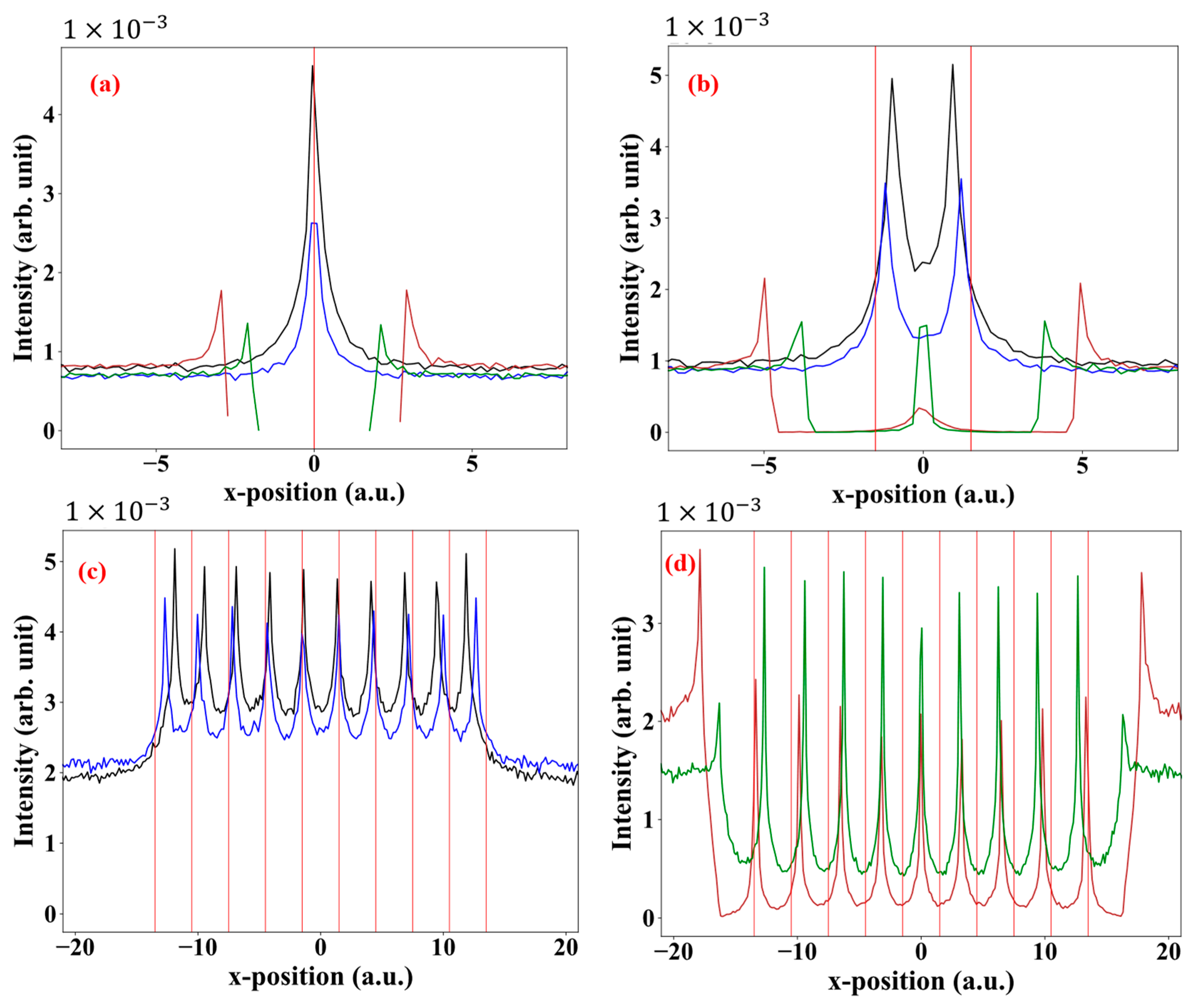
The previous parameters play the most important role in shaping the intensity of the projectiles on the detector. Figure 3 shows the intensity distribution of electrons and positrons projectiles at the detection plane for different proton numbers in the line configuration. The area taken into the discussion of the intensity will span the entire x-axis, but for the y-axis, it will be (−1 to 1 a.u.) for the one- and two-proton systems; however, for the ten-proton system it will be (−3 to 3 a.u.) due to the bigger Coulomb potential.
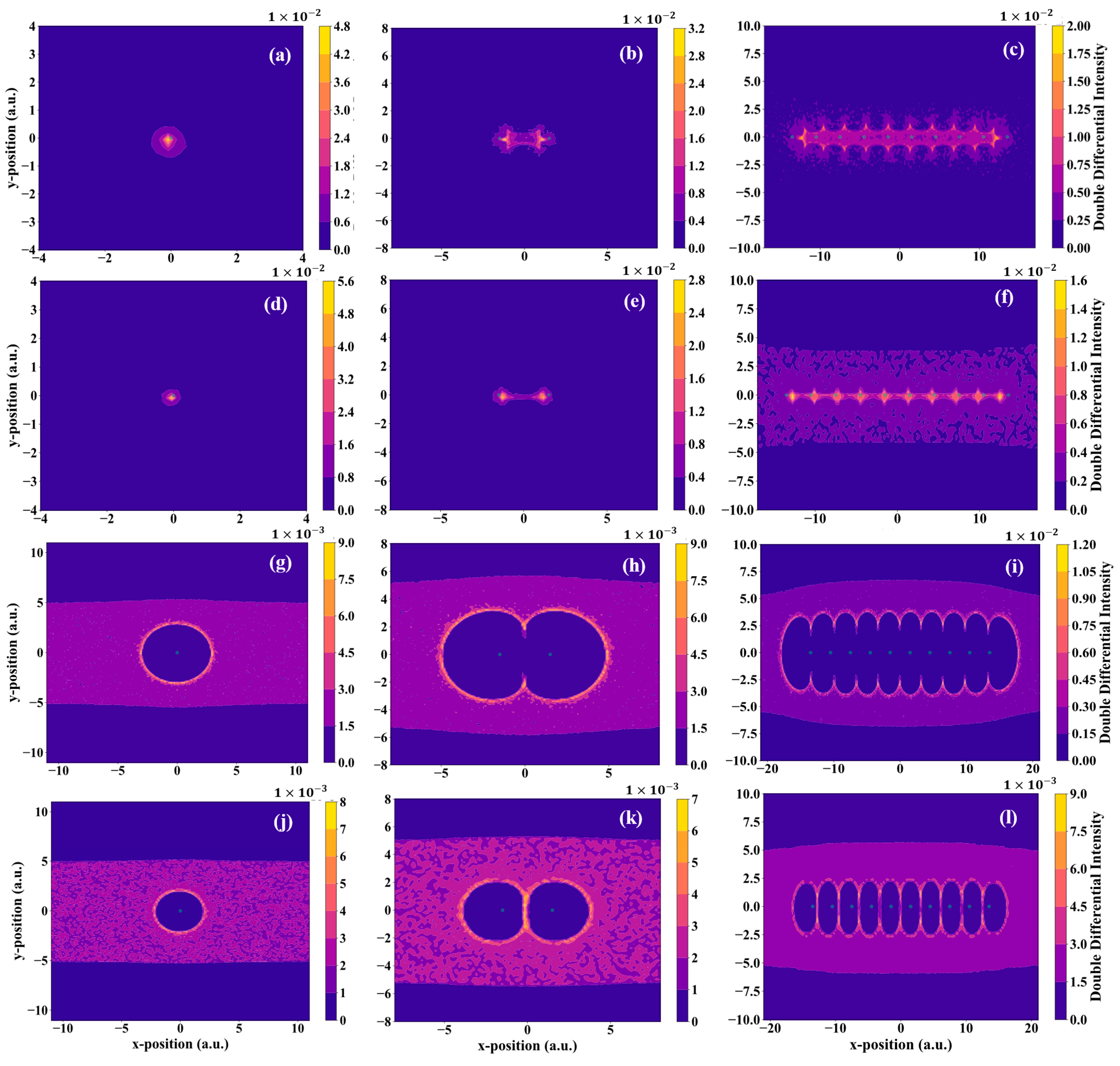
It is also interesting to study the intensity on the entire two-dimensional detection plane to see the overall dynamics of the system (see Figure 4). We start with the system of the one-proton case (see Figure 3a and Figure 4a,d,gj. We can see that the intensities for lower energy projectiles are bigger than that of the higher energy projectiles. The proton focused the electrons at a very small area leading to the formation of a single cusp-like peak. The cusp is at the coordinate x = 0 and y = 0 on the detection plane which is directly above the proton coordinate x = 0 and y = 0. For the positrons case, a perfect circle formed for the positron free region in the detector, indicating a defocusing effect. This formation is due to the strong Coulomb repulsion between the proton and the positrons and leading to the formation of two peaks at equal distances away from the proton. We can also see that the cusp of the 500 eV electrons is broader than that of the 1000 eV electrons. However, for the case of positron, this picture is different. According to Figure 4g,j the intensities show the formation of perfect circles. The radius of the circle formed in the case of 500 eV positrons is around 3 to 3.5 a.u. which is larger than the circle of 1000 eV positrons which is around 2.25 to 2.5 a.u.
For the two-proton system (see Figure 3b and Figure 4b,e,h,k), the first thing to notice is that the intensities of the lower energies projectiles are still larger than that of the higher energy projectiles, and the 500 eV electron distribution is now much broader on the y-axis compared to the 1000 eV electron distribution. Furthermore, two peaks of electrons are formed; here, the peaks are not directly above the protons’ positions, but they are shifted inside between the protons. This shift of the peak is because the electrons are under the influence of two attractive Coulomb potentials. We note that the peak for the 500 eV electrons is slightly shifted inside more than that for the 1000 eV electrons. Going to the case of positrons, the shapes of circles are deformed to a half circle on the outer side, and to a half ellipse between the two protons. The radius of the lower energy positrons is still larger than that of the higher energy positrons (see Figure 4h,k). Furthermore, for the 1000 eV positrons, the intensity between the protons is in the form of a line of positrons perpendicular to the horizontal line of the configuration of the protons, which is because of the low potential difference at the centre between the two protons.
For the case of the ten protons, we note that there are nine inner regions (i.e., between each two adjacent protons) and another two regions outside the configuration of the protons. Comparing the outer regions of the ten protons case with the outer region of the two protons case for positrons projectiles, we see some similarities, such as, the cusp shape and the intensity. The intensity is larger in the outer region compared to the inner region in both cases. However, the potential energy as well as the intensity in the ten protons case for positron projectiles is much bigger than that of the two protons case. Moreover, the most outer peak in the ten protons case is shifted farther from the most outer proton compared to the two protons case. In the inner region, the Coulomb potential is higher at areas near the outer protons and decreases as we move toward the centre of the configuration. This is due to the symmetry of the configuration, i.e., the Coulomb potential is very weak at the centre of the configuration and it could reach zero. For the case of electrons, the focusing pattern for 1000 eV electrons is like a connected point, while for 500 eV electrons it appears like a thick chain (see Figure 4c,f) because the total Coulomb potential of the protons has a higher effect on the electrons with lower kinetic energies. For the case of positrons, the radii of the focussing pattern became larger on the y-axis, and the ellipses became more compressed between the protons (see Figure 4f,l). This is also due to the Coulomb potential having a larger effect on the low-energy positrons. Increasing the number of protons to ten creates a high repulsive potential area in the vicinity of the protons which prevents a considerable number of 500 eV positrons from passing between the protons. However, this high potential was unable to prevent some positrons with 1000 eV kinetic energies from penetrating the protons line at certain distances (see Figure 4f,l). Regarding the positions of the peaks, in the case of electrons, the peaks are formed exactly above the protons at the centre of the configuration. While we move toward the outer protons, we note that the peaks are shifted towards the centre; as mentioned earlier, the potential is higher at the outer protons and is attractive, which leads to the shift of the peaks toward the centre (see Figure 3c). In case of positrons, the peaks are exactly at the midpoint between the protons at the centre, but the peaks are shifted outward while we move toward the outer protons, this shift is due to the higher repulsive coulomb potential at outer protons (see Figure 3d). Furthermore, in the inner regions, the peaks of the 1000 eV positrons have higher intensities than that of the 500 eV positrons. In the outer regions, it is the opposite, and the peaks of 500 eV positrons have the higher intensities.
We note that the spectra we acquired from the results of the simulations are approximately like the interference patterns of light on a screen after passing through Young’s slits. The peaks in our results are analogous to constructive interference, while the valleys are analogous to destructive interference. It is well known that light scattering from the two slits produces multiple intensity peaks represented by bright fringes, while the dark fringes represent the valleys between the peaks, see Grossman et al. [37]. However, in the case of particle collisions, the constituent atoms of the target work as slits [33], and the number of obtained peaks are equal to the number of the target atoms. Zhou et al. [38] studied the collision of molecular deuterium (D2) with ground state helium. They plotted the projectile counts as a function of scattering angles, and they got two maxima. The cross sections of Murray et al. [33] as a function of the analyser angles show also two maxima. The work of both Zhou et al. [38] and Murray et al. [33] are equivalent to our two-proton system. In the case of electrons, the number of peaks is equal to the number of protons, but in the case of positrons, the number of peaks is equal to the number of protons plus one.
4. Conclusions
We have presented theoretical studies of electron and positron interactions with protons aligned in a one-dimension line. The periodic proton line was artificially generated in such a way that the individual protons were fixed in a certain position. The electron and positron trajectories passing through these periodic multiple scattering objects were calculated using a classical trajectory Monte Carlo method. The purpose of our present work was twofold. First, the results obtained from these model calculations will help us to further study more complicated systems such as two-dimensional materials like graphene. These calculations also help us to classically mimic the same structure like that produced by the interference effect.
We found that the proton line has a focusing effect on electrons and defocusing effect on the positrons. The focusing and defocusing degree depends on many parameters. These parameters are: the number of protons and their formation, the incident kinetic energy, the charge of the projectiles, and the impact parameters. Furthermore, as an interesting point, the position spectra of electron and positron projectiles on the detector can be compared with the interference patterns of light in Young’s double-slit experiment [39]. In the spectra, cusps are formed. The number of cusps in the electron–proton interactions is equal to the number of protons and the number of cusps in the positron–proton interaction is equal to the number of protons plus one. The cusps in the electron–proton spectra indicate the points of focusing, while the cusps in the positron–proton spectra are formed at the intersection of a line passing the protons configuration and the sides of an oval shape are created due to defocusing. Hence, each pair of cusps in the positron–proton spectra indicates the position of a defocusing point between them. In the future, based on our current work, we are planning to expand our work to a more complicated structure, such as a proton lattice and graphene.
Author Contributions
Methodology, M.S.A.-A.; Supervision, K.T.; Writing—original draft, M.S.A.-A.; Writing—review and editing, M.S.A.-A. and K.T. All authors have read and agreed to the published version of the manuscript.
Funding
This research received no external funding.
Informed Consent Statement
Not applicable.
Data Availability Statement
The data that support the findings of this study are available from the corresponding author upon reasonable request.
Acknowledgments
This work has been carried out within the framework of the EUROfusion Consortium, funded by the European Union via the Euratom Research and Training Programme (Grant Agreement No 101052200—EUROfusion). The views and opinions expressed are, however, those of the author(s) only and do not necessarily reflect those of the European Union or the European Commission. Neither the European Union nor the European Commission can be held responsible for them.
Conflicts of Interest
The authors declare no conflict of interest.
References
- Tőkési, K. The role of projectile double scattering in positron–atom collisions. Radiat. Phys. Chem. 2007, 76, 624–626. [Google Scholar] [CrossRef]
- Afroz, S.; Haque, M.M.; Fazlul Haque, A.K.; Jakubassa-Amundsen, D.H.; Patoary, M.A.R.; Shorifuddoza, M.; Khandker, M.H.; Uddin, A.M. Elastic scattering of electrons and positrons from 115In atoms over the energy range 1 eV–0.5 GeV. Results Phys. 2020, 18, 103197. [Google Scholar] [CrossRef]
- Makochekanwa, C.; Kawate, H.; Sueoka, O.; Kimura, M.; Kitajima, M.; Hoshino, M.; Tanaka, H. Total and elastic cross-sections of electron and positron scattering from C3H4 molecules (allene and propyne). Chem. Phys. Lett. 2003, 368, 82–86. [Google Scholar] [CrossRef]
- Sueoka, O.; Makochekanwa, C.; Tanino, H.; Kimura, M. Total cross-section measurements for positrons and electrons colliding with alkane molecules: Normal hexane and cyclohexane. Phys. Rev. A 2005, 72, 042705. [Google Scholar] [CrossRef]
- Horowitz, C.J. Parity violation in astrophysics. Eur. Phys. J. A 2005, 24, 167–170. [Google Scholar] [CrossRef]
- Hossain, M.I.; Haque, A.; Patoary, M.A.R.; Uddin, M.A.; Basak, A.K. Elastic scattering of electrons and positrons by atomic magnesium. Eur. Phys. J. D 2016, 70, 41. [Google Scholar] [CrossRef]
- Crooks, G.B.; Rudd, M.E. Experimental Evidence for the Mechanism of Charge Transfer into Continuum States. Phys. Rev. Lett. 1970, 25, 1599. [Google Scholar] [CrossRef] [Green Version]
- Kövér, A.; Szabó, G.; Gulyás, L.; Tőkési, K.; Berényi, D.; Heil, O.; Groeneveld, K.O. Electron emission at backward angles from He2+, He+ (2 mev) → He, Ne, Ar collision systems. J. Phys. Colloq. 1987, 48, C9-289–C9-291. [Google Scholar] [CrossRef]
- Kövér, A.; Szabó, G.; Gulyás, L.; Tőkési, K.; Berényi, D.; Heil, O.; Groeneveld, K.O. The electron loss process at backward observation angles in collision systems He+ (2 MeV)-He, Ne, Ar. J. Phys. B At. Mol. Opt. Phys. 1988, 21, 3231. [Google Scholar] [CrossRef]
- Tőkési, K.; Mukoyama, T. Theoretical Investigation of the ECC Peak for Charged Particles with the CTMC Method. Bull. Inst. Chem. Res. Kyoto Univ. 1994, 72, 62–68. [Google Scholar]
- Gagyi-Pálffy, A.C.; Barna, I.F.; Gulyás, L.; Tőkési, K. Angular Differential Cross-Section for Ionization of Helium in C6+ Ion Collision. Chin. Phys. Lett. 2004, 21, 1258. [Google Scholar] [CrossRef]
- Tőkési, K.; Kövér, A. Existence of the electron capture to the continuum peak at positron impact. Nucl. Instrum. Methods Phys. Res. B Beam Interact. Mater. At. 1999, 154, 259–262. [Google Scholar] [CrossRef]
- Tőkési, K.; Kövér, A.J. Electron capture to the continuum at 54.4 eV positron-argon atom collisions. Phys. B At. Mol. Opt. Phys. 2000, 33, 3067. [Google Scholar] [CrossRef]
- Barna, I.F.; Tőkési, K.; Gulyás, L.; Burgdörfer, J. Total and angular differential cross sections of electrons emitted in collision between antiprotons and helium atoms. Radiat. Phys. Chem. 2007, 76, 495–498. [Google Scholar] [CrossRef]
- Tőkési, K.; Sarkadi, L.; Mukoyama, T.J. Model calculation of the electron capture to the continuum peak at neutral projectile impact. Phys. B At. Mol. Opt. Phys. 1997, 30, L123. [Google Scholar] [CrossRef]
- Hillenbrand, P.M.; Hagmann, S.; Groshev, M.E.; Banas, D.; Benis, P.E.; Brandau, C.; De Filippo, E.; Forstner, O.; Glorius, J.; Grisenti, R.E.; et al. Radiative electron capture to the continuum in U 89 + + N 2 collisions: Experiment and theory. Phys. Rev. A 2020, 101, 022708. [Google Scholar] [CrossRef] [Green Version]
- Nanos, S.; Quinto, M.A.; Madesis, I.; Laoutaris, A.; Zouros, T.J.M.; Rivarola, R.D.; Monti, J.M.; Benis, E.P. Subshell contributions to electron capture into the continuum in MeV/u collisions of deuterons with multielectron targets. Phys. Rev. A 2020, 105, 022806. [Google Scholar] [CrossRef]
- Olson, R.E.; Salop, A. Charge-transfer and impact-ionization cross sections for fully and partially stripped positive ions colliding with atomic hydrogen. Phys. Rev. A 1977, 16, 531–541. [Google Scholar] [CrossRef]
- Tőkési, K.; Hock, G. Double electron capture in collision up to 1500 keV/amu projectile impact. J. Phys. B 1996, 29, L119–L125. [Google Scholar] [CrossRef]
- Olson, R.E.; Reinhold, C.O.; Schultz, D.R. High-Energy Ion-Atom Collisions. In Proceedings of the IVth Workshop on High-Energy Ion-Atom Collision Processes, Debrecen, Hungary, 17–19 September 1990. [Google Scholar]
- Tőkési, K.; DuBois, R.D.; Mukoyama, T. Interaction of positronium with helium atoms—The classical treatment of the 5-body collision system. Eur. Phys. J. D 2014, 68, 255. [Google Scholar] [CrossRef]
- Tőkési, K.; Hock, G. Versatility of the exit channels in the three-body CTMC method. Nucl. Instrum. Meth. Phys. Res. B 1994, 86, 201–204. [Google Scholar] [CrossRef]
- Tőkési, K.; Barna, I.F.; Burgdörfer, J. Ionization of helium in positron impact. Nucl. Instrum. Methods Phys. Res. B 2005, 233, 307–311. [Google Scholar] [CrossRef]
- Kavčič, M.; Tőkési, K. Single and double K-shell ionization cross sections of silicon. Radiat. Phys. Chem. 2007, 76, 542–545. [Google Scholar] [CrossRef]
- Ziaeian, I.; Tőkési, K. Interaction of Be4+ and Ground State Hydrogen Atom—Classical Treatment of the Collision. Atoms 2020, 8, 27. [Google Scholar] [CrossRef]
- Atawneh, S.J.A.; Asztalos, Ö.; Szondy, B.; Pokol, G.I.; Tőkési, K. Ionization Cross Sections in the Collision between Two Ground State Hydrogen Atoms at Low Energies. Atoms 2020, 8, 31. [Google Scholar] [CrossRef]
- Acebal, E.; Otranto, S. Influence of the projectile charge sign in light particle single ionization of H2O. Eur. Phys. J. D 2019, 73, 91. [Google Scholar] [CrossRef]
- Tőkési, K. Double electron excitation of helium by charged particle impact. Nucl. Instrum. Methods Phys. Res. B 2019, 233, 266–269. [Google Scholar] [CrossRef]
- Oliveira, V.; Herbert, A.; Santos, A.; Tőkési, K. Electron capture and loss of O+ projectile in collision with water near the Bragg Peak Energies. Eur. Phys. J. D 2019, 73, 146. [Google Scholar] [CrossRef]
- Tőkési, K.; Varga, D. Energy distribution of elastically scattered electrons from double layer samples. Nucl. Instrum. Methods Phys. Res. Sect. B Beam Interact. Mater. At. 2016, 369, 109–121. [Google Scholar] [CrossRef]
- Sulik, B.; Tőkési, K. Accelerating Multiple Scattering of Electrons by Ion Impact: Contribution to Molecular Fragmentation and Radiation Damages. Adv. Quantum Chem. 2007, 52, 253–276. [Google Scholar]
- Young, T. The Bakerian lecture: Experiments and calculations relative to physical optics. Philos. Trans. R. Soc. 1804, 94, 1–16. [Google Scholar]
- Murray, A.J.; Hussey, M.J.; Kaiser, C.; Gao, J.; Madison, D.H. Electron impact ionization of molecules at low to intermediate energies—A search for Young’s double slit type interferences. J. Electron Spectrosc. Relat. Phenom. 2007, 161, 11–16. [Google Scholar] [CrossRef]
- Steiger, T.D.; Stehr, J.; Griffin, H.C.; Rogers, J.H.; Skalsey, M.; Van House, J. Development of intense, long-lived positron sources. Nucl. Instrum. Methods M Phys. Res. 1990, A299, 255–260. [Google Scholar] [CrossRef]
- Uesugi, Y.; Akagi, T.; Chehab, R.; Dadoun, O.; Furukawa, K.; Kamitani, T.; Kawada, S.; Omoric, T.; Takahashi, T.; Umemori, K.; et al. Development of an intense positron source using a crystal-amorphous hybrid target for linear colliders. Nucl. Instrum. Methods Phys. Res. B 2014, 319, 17–23. [Google Scholar] [CrossRef] [Green Version]
- Maekawa, M.; Wada, K.; Kawasuso, A. Development a new positron source for spin-polarized positron beam generation. Nucl. Inst. Methods Phys. Res. B 2020, 480, 49–55. [Google Scholar] [CrossRef]
- Gossman, D.; Perez-Garcia, B.; Hernandez-Aranda, R.I.; Forbes, A. Optical interference with digital holograms. Am. J. Phys. 2016, 84, 508. [Google Scholar] [CrossRef] [Green Version]
- Zhou, H.; Perreault, W.E.; Mukherjee, N.; Zare, R.N. Quantum mechanical double slit for molecular scattering. Science 2021, 374, 960–964. [Google Scholar] [CrossRef]
- Hecht, E. Interference. In Optics, 5th ed.; Borthakur, M., Tiwari, V., Eds.; Pearson Education Limited: Essex, UK, 2017; pp. 405–408. [Google Scholar]
Figure 1.
Schematic diagram of our system for two protons case calculations mimicking the interaction between the projectile and the two protons. R01, R02 and R12 are the distances between electron–proton1, electron–proton2 and proton1–proton2, respectively. Distance between protons R12 is constant during the simulation. L1 is the vertical distance between electron source and protons, L2 is the vertical distance between protons and the detector.

Figure 2.
Trajectories of projectiles in three configurations of the target system, (a) electrons with one proton, (b) positrons with one proton, (c) electrons with two protons, (d) positrons with two protons, (e) electrons with ten protons, (f) positrons with ten protons. Blue solid lines: electrons with initial energy of 500 eV, red dashed lines: electrons with initial energy of 1000 eV, green solid lines: positrons with initial energy of 500 eV, black dashed lines: positrons with initial energy of 1000 eV, red circle shows positions of the protons.

Figure 3.
Intensity distribution of projectiles at the detection plane: (a) one-proton system, (b) two-proton system, (c) ten-proton system with electrons, (d) ten-proton system with positrons. Vertical red line indicates the x-position of protons. Black solid line: 500 eV electrons, blue solid line: 1000 eV electrons, brown solid line: 500 eV positrons and green solid line: 1000 eV positrons.

Figure 4.
Double differential intensity distribution of projectiles at the two-dimensional detection plane, one-proton system with (a) 500 eV electrons, (d) 1000 eV electrons, (g) 500 eV positrons and (j) 1000 eV positrons; two-proton system with (b) 500 eV electrons, (e) 1000 eV electrons, (h) 500 eV positrons and (k) 1000 eV positrons; ten-proton system with (c) 500 eV electrons, (f) 1000 eV electrons, (i) 500 eV positrons and (l) 1000 eV positrons. The small green circles indicate the position of the protons.

Disclaimer/Publisher’s Note: The statements, opinions and data contained in all publications are solely those of the individual author(s) and contributor(s) and not of MDPI and/or the editor(s). MDPI and/or the editor(s) disclaim responsibility for any injury to people or property resulting from any ideas, methods, instructions or products referred to in the content. |
© 2023 by the authors. Licensee MDPI, Basel, Switzerland. This article is an open access article distributed under the terms and conditions of the Creative Commons Attribution (CC BY) license (https://creativecommons.org/licenses/by/4.0/).
Share and Cite
MDPI and ACS Style
Al-Ajaleen, M.S.; Tőkési, K. Interaction of Electrons and Positrons with Protons Aligned in One-Dimension Line. Atoms 2023, 11, 46. https://doi.org/10.3390/atoms11030046
AMA Style
Al-Ajaleen MS, Tőkési K. Interaction of Electrons and Positrons with Protons Aligned in One-Dimension Line. Atoms. 2023; 11(3):46. https://doi.org/10.3390/atoms11030046
Chicago/Turabian StyleAl-Ajaleen, Musab S., and Károly Tőkési. 2023. "Interaction of Electrons and Positrons with Protons Aligned in One-Dimension Line" Atoms 11, no. 3: 46. https://doi.org/10.3390/atoms11030046
Note that from the first issue of 2016, this journal uses article numbers instead of page numbers. See further details here.