Article

DNCL: Hybrid DOA Estimation and NMDS Cooperative Multi-Target Localization for RFID

School of Microelectronics, Tianjin University, Tianjin 300072, China
*
Author to whom correspondence should be addressed.
Electronics 2023, 12(7), 1742; https://doi.org/10.3390/electronics12071742
Submission received: 10 March 2023 / Revised: 31 March 2023 / Accepted: 1 April 2023 / Published: 6 April 2023
(This article belongs to the Special Issue RFID Technology and Its Applications)

Abstract

:
Passive radio frequency identification (RFID) tags have been widely used in logistics, supply chain, warehousing, and other fields. However, for RFID-based automatic inventory management in warehouses, the deployment of current methods is more complex, and the localization range still has some limitations. This paper proposes DNCL, which is a hybrid passive RFID localization scheme based on direction-of-arrival (DOA) estimation and nonmetric multidimensional scaling (NMDS) to achieve spatial coordinate localization of tagged objects on shelves or racks using a single antenna for simple 1D scanning. DNCL uses antenna dynamic scanning to generate a virtual antenna array for the dynamic information capture of tags in the scene, which helps eliminate the phase shift produced by ambient noise. We apply the angle profile linear model to identify the characteristics of each tag and introduce the NMDS algorithm to improve the robustness of the scheme through the fixed layout of the reference tags, which can reliably estimate the coordinates of the tagged objects in the space. This paper realizes a prototype system and validated its practical performance in real complex situationse by COTS RFID devices. The results indicate that DNCL can achieve high accuracy for the localization of passive tags in free space.

1. Introduction

With the further development of mobile communication industry and the rapid rise of the Internet of Things (IoT), the research demand for wireless localization and sensing technologies has greatly increased. People hope they can achieve comprehensive and in-depth sensing of objects such as localization, identification, and tracking in various scenarios, including location-based services, indoor navigation, and tracking of objects [1,2]. A variety of indoor localization systems based on various wireless communication technologies have been developed to suit the demanding needs of indoor localization sensing [3,4], such as wireless fidelity (WiFi) localization [5,6], Bluetooth localization, ultrawideband (UWB) localization [7,8], ZigBee localization, and ultrahigh frequency (UHF) RFID localization [9,10,11,12]. Among these, passive UHF RFID technology has gained tremendous attention from academics and industry because of its low cost, broad reading range, ease of use, and unique benefits in the fields of localization and identification at the same time. RFID technology has been widely employed in logistics management, asset tracking, and warehousing inventory control application areas. By simply adding an RFID tag to an item, the details of the item can be read using a backscatter signal using a reader.
There are many different types of methods that have been proposed for RFID localization systems, including the conventional time-based methods [13] like time of arrival (TOA) and time difference of arrival (TDOA), but their hardware requirements are extremely high because the localization accuracy depends on the signal bandwidth of the receiving device, line-of-sight transmission between devices, etc. The localization method based on received signal strength (RSS) is the most commonly used RFID tag localization method due to its easier and more flexible implementation [14,15,16,17,18]. The LANDMARC [14] project has pioneered the use of RSS similarity between the target tag and the reference tag for RFID tag localization using fingerprints. However, regrettably, in addition to distance, RSS is also susceptible to background noise from the signal propagation environment, non-line-of-sight factors, and multipath factors, resulting in low localization accuracy in complicated indoor environments.
In contrast, approaches relying on phase information can achieve more precise localization since the phase characteristics are more stable and more sensitive to distance. They are basically categorized into holographic-based methods, distance-based methods, and DOA-based methods [19,20]. Holographic methods first divide the region into grids, then evaluate the likelihood that each grid represents a tag location. Tagoram [21] used phase values to generate differential augmented holograms to obtain the probability that all points become RF sources, and chooses the position with the largest probability as the tag location. BackPos [22] converts the localization problem into a hyperbolic model through using the relationship between phase difference and distance difference of signals received by antennas at different locations. HyLoc is proposed in [23], which proposes a simple yet effective RFID tag localization method on the basis of the hyperbolic model. MuSLoc [24] uses an antenna array to accomplish high-precision indoor localization by utilizing a DOA-based methodology combined with a heuristic location search strategy. RF-IDraw [19] similarly employs the DOA through angle information gathered to develop an RFID accurate tracking system to complete the reconstruction of user gestures. The position of each tag was calculated by using the direction of arrival detected by three directional antenna arrays positioned on the outside of the plane in [25]. The use of a multi-signal classification algorithm combined with an RFID tag array to estimate the object pose is implemented in [26]. The tag position was further triangulated by manipulating the shape of the radiation direction map of the reader-transmitting antenna array to estimate the tag direction in [27].
The DOA uses the phase difference between individual elements in an antenna array to estimate the directional angle of the signal arriving at the array reference element. However, the good accuracy of DOA estimation is connected with the number of elements in the antenna array, and, in practice, it is not very feasible to locate low-cost RFID tags by deploying bulky, costly, and multi-element antenna array. Inspired by synthetic aperture radar (SAR) high-resolution imaging [28,29,30,31,32], one can use a single antenna moving scan method to obtain phase information. Through the relative motion of the antenna and the objects, the signals received by the antenna at different sampling point positions during the motion were combined to construct a virtual antenna array for DOA estimation. This approach has considerable practical value, as it does not require hardware configuration changes or sophisticated antenna array hardware installations.
In the last ten years, although a great number of passive UHF-RFID tag localization methods have been proposed, practical applications still face challenging problems that demand further research, notably for RFID-based automated inventory management in warehouses. 3Dloc [33] utilizes a continuous mobile RFID antenna, and the scanning of marked objects in the 2D space in front of the marked objects can realize the three-dimensional localization of the tagged objects. RF-3DScan [34] enables the 3D reconstruction of the tagged packages. Based on RSS and measured phase, ReLoc [35] proposes a hybrid relative passive RFID localization technique, which is a practical item-level inventory management solution.
In order to better localize objects using RFID, several reference tag-based approaches have been proposed to improve accuracy. PinIt [36] compared and matched the multipath profile of the target tag with the reference tags deployed in the environment, based on identifying the nearest neighbors of the desired tag and then localizing it. The fingerprint localization technique and the NMDS algorithm are combined in [37] to achieve cooperative indoor RFID multi-tag localization. However, it chooses to use the RSS information received by the antennas, and this localization method has large errors in indoor scenarios where complex multipaths exist. In order to achieve RFID localization in the space, most of them need two antennas or two-dimensional scanning, which is more cumbersome to deploy.
This paper proposes DNCL, a localization approach based on DOA directional angle information combined with the nonmetric multidimensional scaling algorithm (NMDS). Through the use of phase information obtained from a 1D scan with a single antenna, DNCL provides spatial coordinate localization of tagged objects on the shelves or racks, as depicted in Figure 1. The main contributions of this paper are as follows:
(1)
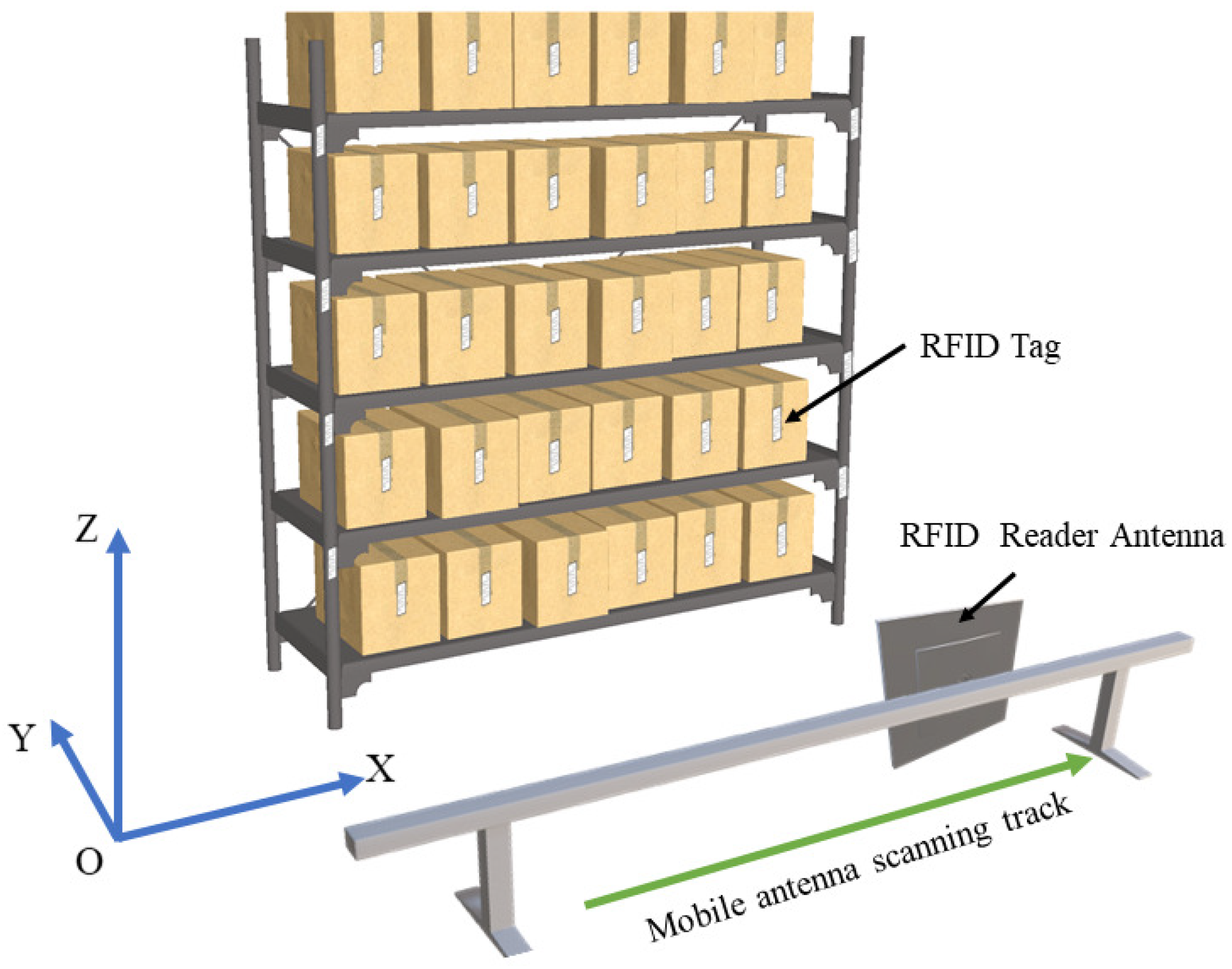
Since different hardware characteristics of different antennas will introduce different phase errors in phase measurement, which are difficult to determine but hard to ignore, this paper is inspired by the principle idea of synthetic aperture radar and designs a phase correction method based on antenna moving scan to build a virtual antenna array, which can effectively eliminate the phase shift errors caused by hardware.
(2)
We propose a Toeplitz rank recovery method for the DOA estimation parameters RFID localization method, for the problem of the direction of arrival estimation rank deficit caused by a large number of coherent multipath signal interference in the environment, we use the Toeplitz method to rank recover the signal covariance matrix, which can effectively eliminate the direction of arrival estimation error caused by multipath signal interference.
(3)
This paper constructs a DOA parameter linear model, combines the localization geometry model to obtain the characteristics of each tag, further introduces a non-metric multidimensional scaling algorithm, uses the distance characteristic relationship between tag pairs to construct a phase dissimilarity matrix, and completes the target location estimation by coordinates conversion with reference tag coordinates to achieve high-precision and highly robust RFID multi-target localization.
(4)
This paper implements a prototype passive RFID positioning system using COTS RFID devices and conducts several experiments in typical indoor scenarios to evaluate the actual performance of the proposed localization algorithm and compare it with other methods. The experimental results show that the proposed localization method can achieve high accuracy and robust spatial localization, and the median error of DNCL method in free space reaches 2 cm.
The rest of this article is structured as follows. The second part lays the groundwork for the subsequent work. This paper problem specification appears in Section 3. The design and analysis of our system are discussed in detail in Section 4. Section 5 evaluates the performance of DNCL through experiments. Finally, Section 6 draws the paper to a conclusion.

2. Background

2.1. RFID Phase Model

The communication between the passive RFID tag and the reader was established based on a backscattering mechanism. Assuming that the distance between the tag and the antenna is d, the signal total propagation distance is 2 d . Along with the phase change introduced by distance, the phase is also affected by the hardware characteristics and orientation of the tag. The phase value that the antenna receives can be represented as
φ = 4 π λ d + φ i n i + e mod 2 π φ i n i = φ A + φ t a g
where λ is the wavelength of the signal and e is the noise-induced measurement error, and φ i n i is referred to as the initial phase and contains phase rotation produced by the antenna hardware circuit and the tag reflection, which are denoted as φ A and φ t a g .

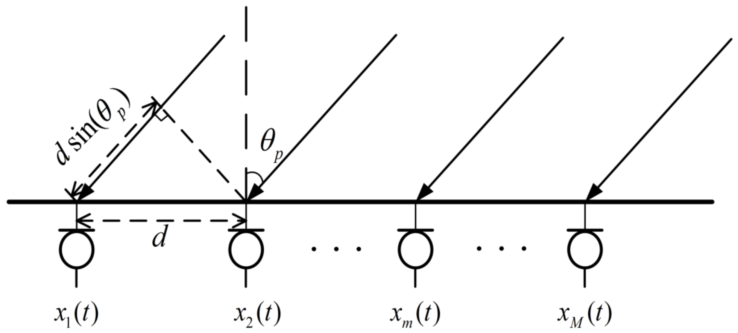
2.2. Direction of Arrival

When the model has N narrowband far-field signals incident on a spatial array with M array element numbers, the signal received by the mth antenna can be written as follows
x m ( t ) = i = 1 N g m i s i ( t τ m i ) + n m ( t ) = i = 1 N g m i s i ( t ) e j ω 0 τ m i + n m ( t ) , m = 1 , 2 , , M
where g m i is the gain of the mth array element to the ith source signal, n m ( t ) is the noise of the mth array element at moment t, and τ m i is the relative time delay of the i-th source signal arriving at the m-th array element.
As illustrated in Figure 2, a signal was received by the antennas in the direction of θ p . The distance between adjacent antennas is denoted by the symbol d. The difference in signal wave range between nearby antennas is d s i n ( θ p ) . As a result, the phase difference of e j 2 π d λ sin ( θ p ) was introduced for adjacent array elements. When described by a matrix, the array signal model could be simply represented as
X ( t ) = A S ( t ) + N ( t )
where N ( t ) is the noise vector, the antenna array receives signal vector X ( t ) = x 1 ( t ) , x 2 ( t ) , , x M ( t ) T is an M × 1 snapshot data vector, A = a θ 1 , a θ 2 , , a θ N is the orientation matrix of the M × N dimensional spatial array, where the column vector a is also an M × 1 dimensional direction vector
a ( θ i ) = 1 , e j 2 π d λ sin ( θ i ) , , e j 2 π d λ ( M 1 ) sin ( θ i ) T
where i = 1 , 2 , , N and ( · ) T denotes the transpose operation.
The super-resolution DOA algorithm is based on eigenstructure analysis of the correlation matrix of the array received data vector. Based on Equation (3), the correlation matrix is expressed as
R X = A R S A H + σ 2 I
where ( · ) H denotes the Hermitian transpose of the matrix, R S = E S S H is the correlation matrix of the source signal vector. Based on the eigenvalue decomposition theorem for matrices, the eigenvalue decomposition of R X is performed as follows
R X = U S Σ S U S H + U N Σ N U N H
where the matrices Σ S and Σ N are the diagonal matrix consisting of the largest N eigenvalues of R X and the diagonal matrix consisting of the remaining eigenvalues, respectively.
R X has M eigenvalues. The eigenvector U S corresponding to the largest N eigenvalues constitutes the signal subspace, and the eigenvector U N corresponding to the other M N eigenvalues constitute the noise subspace. The signal subspace and noise subspace are orthogonal, so the spatial spectral function enable to be constructed as
P M U S I C ( θ ) = 1 a H ( θ ) U N U N H a ( θ )
then the sharp peak of the function represents the DOA of the incident signal.

2.3. Nonmetric Multidimensional Scaling (NMDS)

In wireless sensor network localization [38,39], the multidimensional scaling (MDS) localization algorithm is often applied. Classical MDS obtains distance information between two individual nodes by ranging, then constructs a phase difference matrix that is linearly related to the Euclidean distance between nodes. The relative coordinates of nodes can be obtained from the phase difference matrix using the classical MDS algorithm. Following that, the absolute coordinates of the nodes were obtained using the coordinate system conversion algorithm.
The nonmetric multidimensional scaling (NMDS) is based on non-ranging, which only requires the order of distance magnitudes between nodes to construct the dissimilarity matrix, and the S T R E S S 1 represents the degree of fit between the distance magnitude relationship of nodes to the dissimilarity matrix
S T R E S S 1 = i < j d ^ i j d i j 2 / i < j d i j 2
where d i j denotes the distance from the ith node to the jth node in the relative coordinates, disparities d ^ i j has the same rank order as the dissimilarity matrix [ P i j ] , they satisfy the same monotonic relationship.
The purpose of NMDS is to minimize S T R E S S 1 by making the value of d ^ i j as close to d i j as possible through multiple iterations.
The six main steps of the NMDS algorithm are as follows:
  • Select the initial coordinates X 0 of the position in the target tags space. The initial coordinates could be assigned at random or calculated with classical MDS. Set the threshold ε for S T R E S S 1 , the maximum number of times to iterate k m a x and the initialized number of iteration times k = 0 .
  • After performing k iterations, the Euclidean distance for each node pair was calculated based on the obtained relative coordinates.
    d i j k = X i k X j k 2
  • The pool-adjacent violators (PAV) algorithm was used to generate the rank value matrix based on the phase dissimilarity matrix [ P i j ] , ensuring that they satisfy the weak monotonicity relation.
  • The number of iterations plus 1, update the relative coordinates of the nodes
    x i k = x i k 1 + a m 1 j M , j i 1 d ^ i j k 1 d i j k 1 x j k 1 x i k 1
    y i k = y i k 1 + a m 1 j M , j i 1 d ^ i j k 1 d i j k 1 y j k 1 y i k 1
    where M represents the number of tags. We used a = 0.2 based on Kruskal [40].
  • Use the updated d ^ i j to calculate the value of S T R E S S 1 .
  • If S T R E S S 1 < ε or k > k m a x , stop the iteration, or execute step (3).
The classical multidimensional scaling algorithm was used to determine the initial coordinates X 0 . Since NMDS was made to minimize S T R E S S 1 by performing several iterations, the final answer might fall into a local minimum if there is an error in the selection of the initial coordinates, so setting k m a x can avoid the program from entering an infinite loop.

3. Modeling the Cooperative Localization

In this section, we elaborate on the issues of concern in this paper. We assume that our system is arranged in the scenario of grocery shelves, warehouses, etc. Each object has a passive UHF RFID tag attached to it, and the shelf includes some tags with known positions. All tags have different IDs, and they are interrogated by RFID readers. We can obtain objects identification and signal information (phase, RSS, Doppler shift, etc.) by scanning the tags attached to the objects. In this paper, we employ the signal phase information acquired by the reader.
As shown in Figure 1, all the targets are placed in different positions on the multi-level shelves. We set up a 3D coordinate system, and the antenna starts from the origin and moves along the X-axis to realize the localization of the marked object in the three-dimensional space.

4. System Design

4.1. System Overview

The DNCL algorithm proposed in this paper is an RFID localization method based on the Toeplitz rank recovery DOA estimation combined with NMDS. The DOA estimation was performed by the phase difference received by the reader antenna moving scanning to obtain the angle characteristics of the tags, and, using the linear relationship of constructing the tag angle distribution profile moving with the antenna position, we can derive their distance characteristics. The NMDS algorithm was introduced according to the rank order of different tags’ characteristics combined with the reference tags. DNCL can obtain the 3D spatial absolute coordinates of the passive tags on the shelves or racks shown in Figure 1 since the position of the reference tags is known, and then achieve multi-target cooperative localization. Figure 3 depicts the DNCL algorithm as a flow chart.

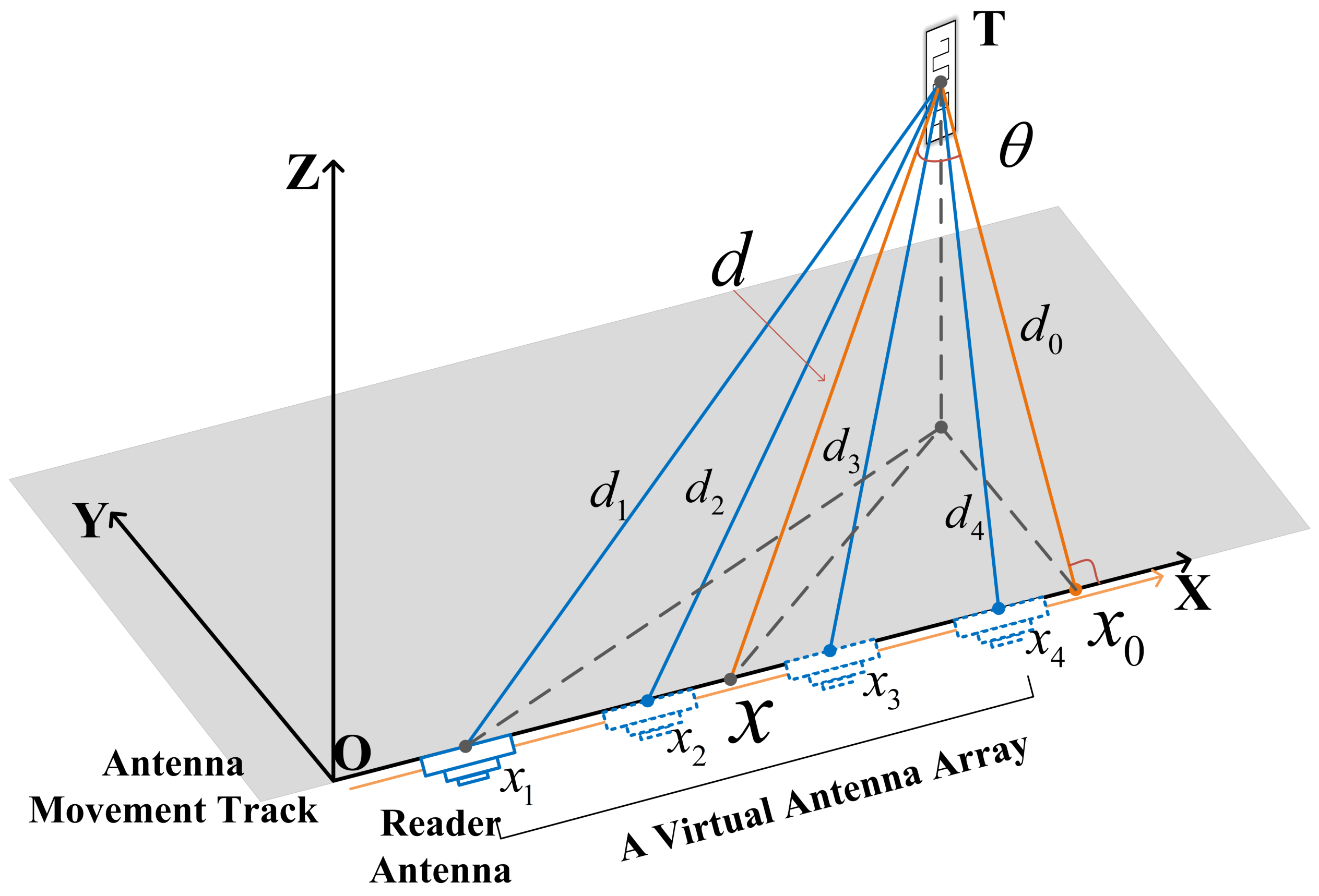
4.2. Virtual Antenna Array Direction of Arrival Estimation

The signal DOA was calculated by the phase difference between the reception of signals from the multiple antennas, and according to Equation (1), it is known that the phase of the signal rotates 2 π with each wavelength distance of the signal propagation. That is, there is an interval of multiple phase periods between the measured phase and the true phase. Specifically, as shown in Figure 4, the signal source is located at T, and the respective distances of the tag and the two positions are d 1 and d 2 . φ 1 and φ 2 are the received signal phases that antenna measured at two different locations, x 1 and x 2 , respectively. The signal phase can be described as:
φ 1 + 2 k 1 π = 4 π λ d 1 + φ i n i + e 1 φ 2 + 2 k 2 π = 4 π λ d 2 + φ i n i + e 2
Since the different hardware characteristics of different antennas can introduce different phase errors in the phase measurement, it is hard to determine φ A . Therefore, we chose to simulate an antenna array inspired by SAR techniques using a mobile antenna, and the measured value of the first phase was used as the calibration reference. In this way, the initial phase φ i n i could be considered as a constant independent of the distance and can be eliminated in the calculation of the phase difference.
Therefore, the phase difference of the antenna at the two locations is Δ φ 1 , 2 = φ 1 φ 2 , and the distance difference is Δ d 1 , 2 = d 1 d 2 , and thus the Equation (12) can be transformed into
Δ φ 1 , 2 + 2 k π = 4 π λ Δ d 1 , 2
The antenna sampling point spacing cannot be arbitrarily selected. If the spacing is too large, the phase delay at adjacent sampling points will exceed 2 π . At this time, the array direction vector cannot identify the specific phase delay in the value, and the problem of phase periodic ambiguity will occur. Therefore, the spacing of adjacent sampling points should not exceed λ / 2 . In RFID-based localization, since the distance between reader antenna and the tag is a round-trip distance, the distance between adjacent sampling points should meet Δ x < λ / 4 .
Due to the complexity of the indoor signal propagation environment, there are a large number of coherent multipath signals in the environment, which can lead to the rank deficiency of the signal covariance matrix, so that the signal eigenvectors diverge into the noise subspace. With the improved MUSIC algorithms, the rank of the signal covariance matrix can be restored. Let I V be the M × M inverse unitary matrix, which can be expressed as
I V = 0 0 1 0 1 0 1 0 0 M × M
In combination with I V , the correlation matrix is transformed into
R x = R + I V R * I V
where R * is the conjugate of R , thus R x is a Toeplitz matrix of Hermite. In general, R is just a Hermite matrix, not a Toeplitz matrix. Using the Toeplitz property, the estimated value R x of the Toeplitz covariance matrix was obtained by modifying R . Therefore, R x is an unbiased estimation of R . Then, the decomposition of R x was performed, and the noise eigenvectors produced during processing were replaced into the MUSIC algorithm, allowing the signal DOA to be accurately approximated.
Since the beam width of the spatial spectrum gradually decreases with the increase of the number of array elements, the resolution of the DOA algorithm is enhanced. However, increasing the number of elements will have a relatively small effect, as the number of elements in an array is very large. Therefore, under the premise of ensuring the estimation performance of the algorithm, the selection of a suitable number of sampling points for DOA estimation should be considered comprehensively.

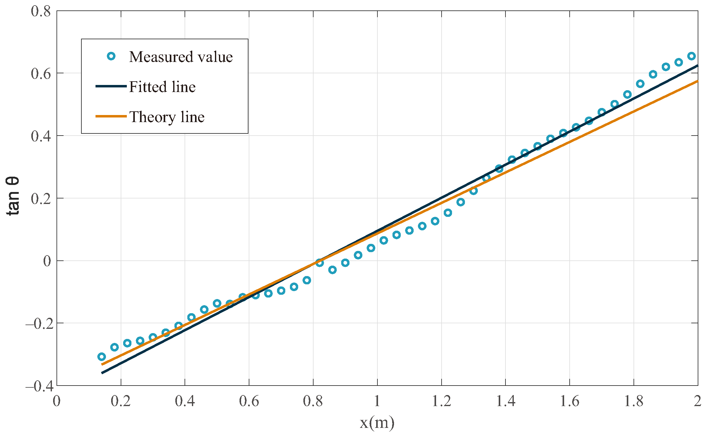
4.3. DOA Parameters Profile

Using the antenna mobile scanning scheme, the reader interrogates the tags when the mobile antenna is at different positions. Based on recorded phase values, the corresponding angle of arrival of the tag at different positions of the antenna can be calculated. Following that, the linear model of DOA parameters was available to determine the position-related parameters of the tag.
As shown in Figure 4, T denotes the position of the tag, x 0 is the projection point of the tag on the linear track of the moving antenna, the x-coordinate of the tag, and d 0 is the vertical distance of the tag to the x-axis. In the system, we make the antenna move linearly along the x-axis, and the position is marked as x, where x = x 4 x 1 2 . The angle θ formed by the straight line l T x 0 and the straight line l T x is the direction of arrival corresponding to the tag when the antenna is located at each sampling point.
According to the geometric relationship of the model shown in Figure 4, a model based on DOA parameters was constructed to compute the location characteristics of the tags. The specific steps are as follows: position of the antenna at x, and the DOA of the tag is θ . Therefore, there exists the geometric relationship
tan θ = x x 0 d 0
this is a linear equation between tan θ and x. Obviously, the reciprocal of the slope of the equation is d, and the intercept on the x-axis is x 0 .
Based on the previous discussion, for each tag, we used X = x 0 , , x i to denote the coordinates of the antenna at different locations. We can obtain its DOA sequence of B = x 0 , θ 0 , , x i , θ i relative to different locations. Further, the sequence Γ = x 0 , tan θ 0 , , x i , tan θ i can be obtained by replacing θ with tan θ . As shown in Figure 5, the d 0 and x 0 corresponding to the tag can be found from the straight lines fitted by the points in the sequence. Moreover, the distance to the tag when the antenna is in different positions can be obtained by
d = d 0 2 + ( x x 0 ) 2
Following that, the distance characteristic vector of the tag can be obtained. To more accurately describe the characteristics of the tags, we further incorporated their angle characteristics. Since the sampling points of the antenna are relatively large, we use the principal component analysis (PCA) method to degrade the dimensionality of the tag characteristics, and we can obtain the characteristic vector ξ = [ d 0 , , d i , θ 0 , , θ i ] of the tag.

4.4. NMDS-Based Cooperative Algorithm

If we let the characteristic vector of the mth tag be ξ ( m ) = [ d 0 ( m ) , , d i ( m ) , θ 0 ( m ) , , θ i ( m ) ] , and the characteristic vector of the nth tag be ξ ( n ) = [ d 0 ( n ) , , d i ( n ) , θ 0 ( n ) , , θ i ( n ) ] , then the dissimilarity between the mth tag and the nth tag can be expressed as
E m n = ξ ( m ) ξ ( n ) 2
Assume that the dissimilarity matrix between the characteristic vectors of different tags is positively related to the actual distance from the mth tag to the nth tag, i.e., the closer the two tags are, the smaller the dissimilarity between them. Assuming that the dissimilarity E m n is the Euclidean distance between the mth tag and the nth tag characteristic vector. The target tags, i.e., the tags to be located, have unknown location coordinates. The Euclidean distance between the tags is used as a matrix element to construct the dissimilarity matrix, which is used as the input of the NMDS algorithm.
P = 0 E 12 E 13 E 1 k E 21 0 E 23 E 2 k E 31 E 32 0 0 0 0 E ( k 1 ) k E k 1 E k 2 E k ( k 1 ) 0
Using the phase dissimilarity matrix, the relative coordinates of the tags can then be obtained according to the NMDS algorithm. Combined with the known coordinates of the reference tags, the absolute coordinates of the tags can be calculated using the coordinate system registration algorithm [41].

5. Experiment and Result Analysis

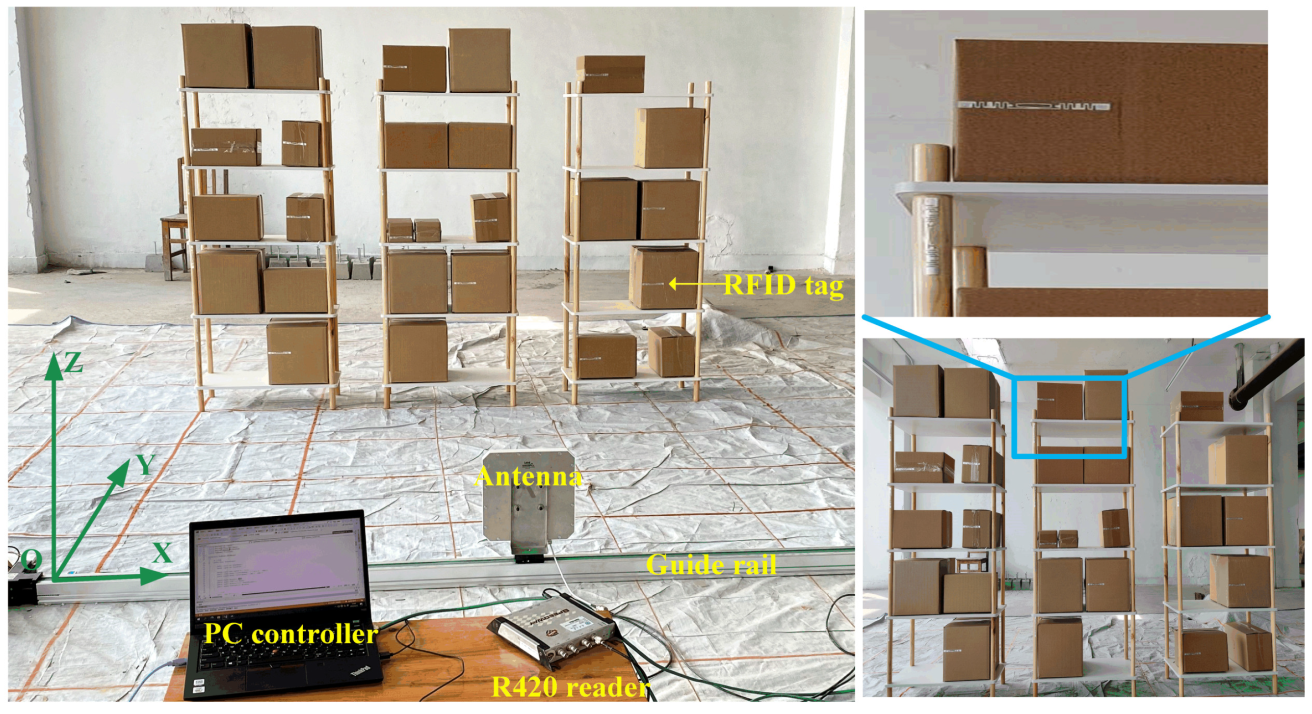
5.1. Experimental Setup

5.1.1. Implementation

In order to validate our proposed cooperative localization approach, a DNCL localization system was implemented. Its hardware system consists mainly of commercial RFID components, among which there is a COTS RFID reader Impinj Speedway R420. The reader hardware has not been changed, follows EPCglobal Gen2 protocol standard, the transmission power is 32.5dbm, and the operating frequency is set to 924.375 MHz. It is connected through an Ethernet cable to a laptop with an AMD Ryzen 5 4600H processor, 3.0 GHz, and 16G RAM. A Laird S9028PCL UHF-RFID antenna is also used, which is a circularly oriented antenna with a 9 dBic gain and a 70 azimuth beamwidth, and a group of UHF Passive RFID tags. At the same time, the AMC4030 localization system was used as a platform for moving the antenna with millimeter accuracy. The AMC4030 controller is connected to the PC controller via a serial port.

5.1.2. System Setup

In order to simulate the situation of the warehouse scenario and realize the localization of goods with passive RFID tags placed on the shelves, the experimental layout is designed as shown in Figure 6. The containers are distributed on three five-level shelves. Some tags are attached to the containers, and some tags are attached to the shelves as reference tags. The antenna is fixed on the guide rail and moves along the straight track parallel to the shelves with a whole rail length of 2 m.

5.1.3. Metrics

In the evaluation of the DNCL system, we used the localization error to measure its localization performance. The localization error is defined as the Euclidean distance in each experiment from the true position to the estimated position of the tag, which may be calculated as
e r r o r = x ^ i x i 2 + z ^ i z i 2
where ( x i , z i ) is the real position of the ith target tag, ( x ^ i , z ^ i ) is the estimated position of the ith target tag.

5.2. Key Parameters Selection

We attempted to experimentally determine the impact of various key parameters on the localization accuracy of the actual DNCL system, namely the window size for each DOA estimation, interrogation interval of the reader antenna, the number of reference tags, and the distance from the reader antenna to tags.

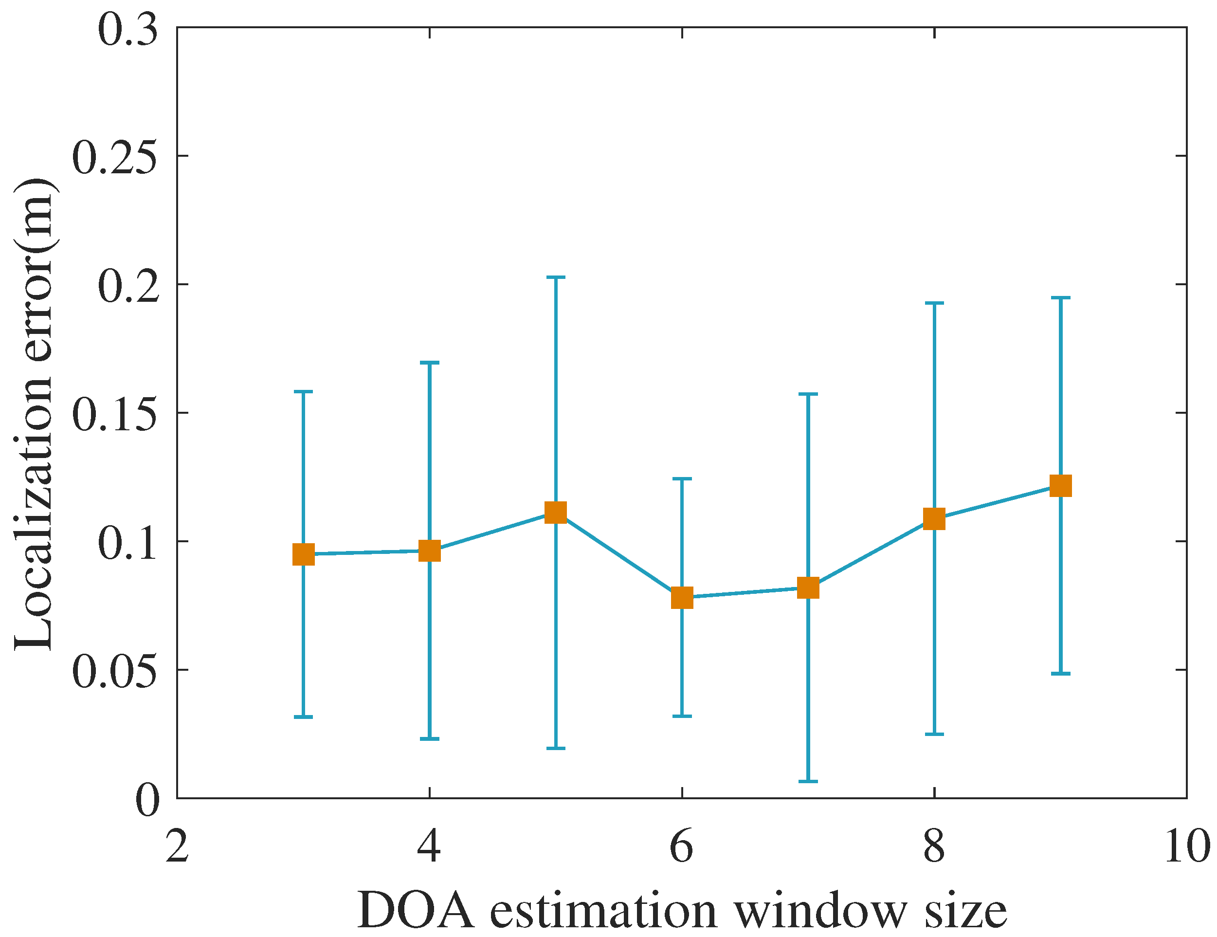
5.2.1. DOA Estimation Window Size

The DOA estimation window size is the number of virtual antenna array elements used for each DOA estimation. According to the principle of DOA estimation, the beamwidth of the spatial spectrum decreases with the increasing number of antenna array elements and the resolution improves. However, when the number of array elements is very large, the effectiveness of increasing the array elements number is relatively small and the amount of operations required to perform DOA estimation increases greatly. Therefore, it is necessary to choose a reasonable estimation window under the condition of ensuring the estimation performance of the algorithm. As shown in Figure 7, we show the trend of localization accuracy of DNCL when the DOA estimation window size is from 3 to 9. The results show that the algorithm localization accuracy does not receive too much influence, and the estimation window size of 6 can be chosen.

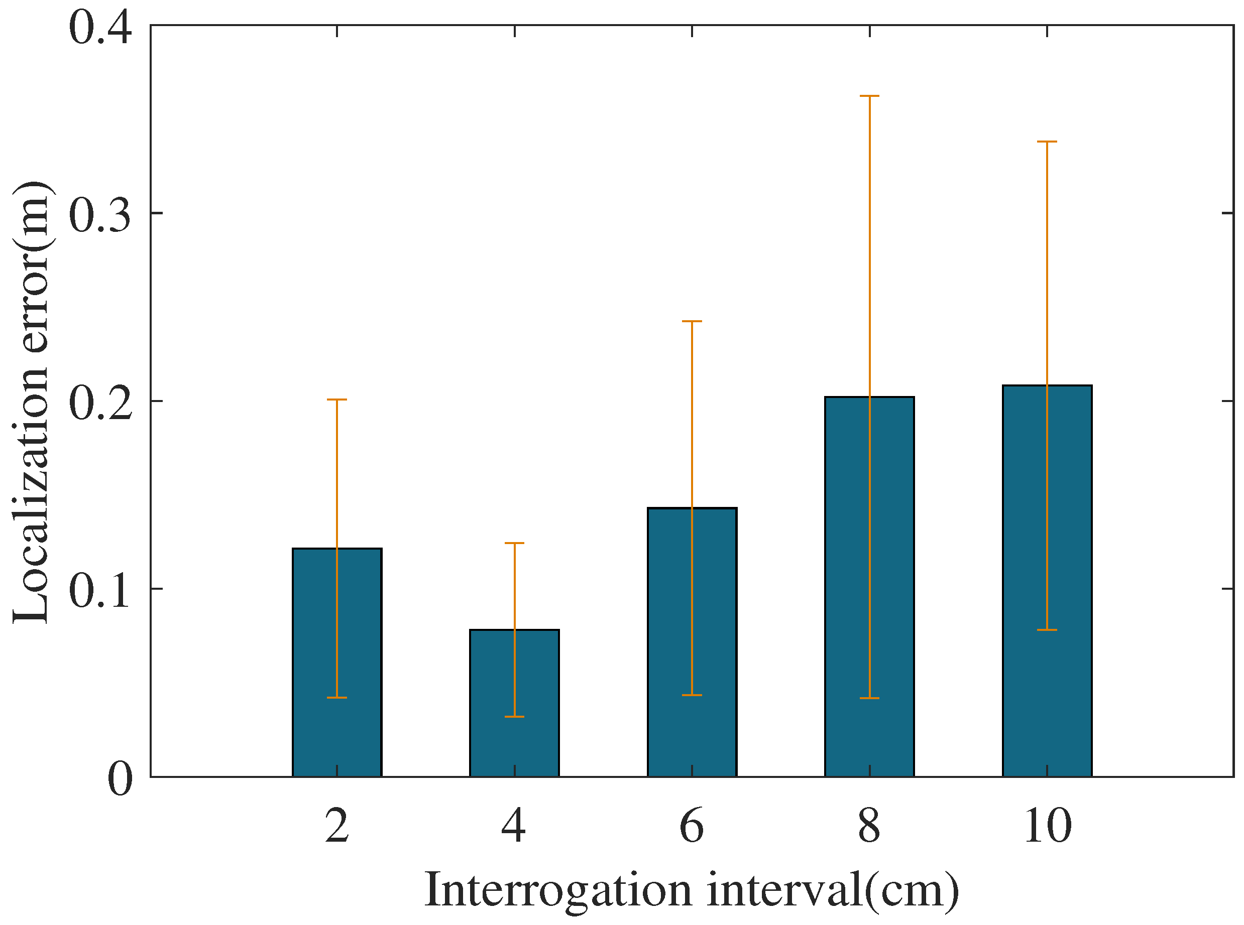
5.2.2. Interrogation Interval

The interrogation interval refers to the distance among two consecutively sampled positions of the mobile antenna, and it is also the array element spacing of the virtual antenna array in DOA estimation. As mentioned in Section 4 above, a larger interval will lead to ’pseudo-peaks’ in the spatial spectrum of the DOA estimation due to the influence of phase periodic ambiguity. When the element spacing of the array is small, the spatial spectrum beamwidth gradually decreases as the array element spacing increases, and the resolution rises. However, as the interrogation interval increases and the number of phase sampling points decreases, the localization accuracy may be affected. To accurately assess the performance of our proposed method under various sampling cases of dense and sparse sampling, we used AMC4030-software control rail to adjust the displacement interval of the reader antenna from 2 cm to 10 cm. The localization error for each experiment is shown in Figure 8. It can be clearly seen that the scheme performs best when the interrogation interval is set at 4 cm.

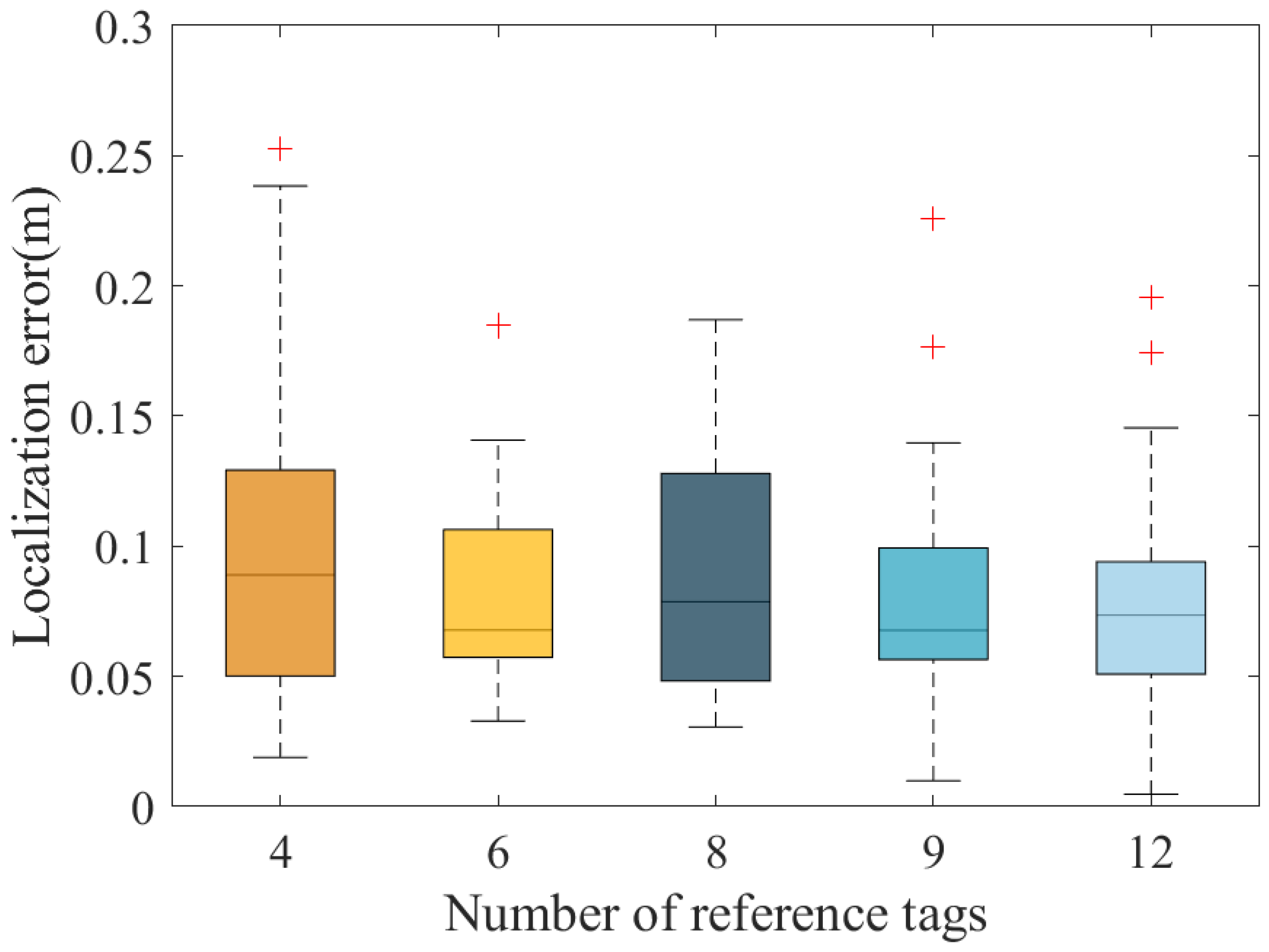
5.2.3. Number of Reference Tags

We also discussed how the DNCL performance is affected by different distributions of reference tags to assess the effect of reference tags placement. We evenly distributed 4, 6, 8, 9, and 12 reference tags in the localization environment while keeping the other arrangements constant. In this case, the localization results of the tags are shown in Figure 9. We observed that the positioning error decreases with increasing the number of reference tags. However, even within the scenario where the number of reference tags is only four, the localization error is tolerable. Because NMDS uses the Euclidean distance information rank order relationship between each pair of tags for localization, the proposed algorithm has a high tolerance for errors.

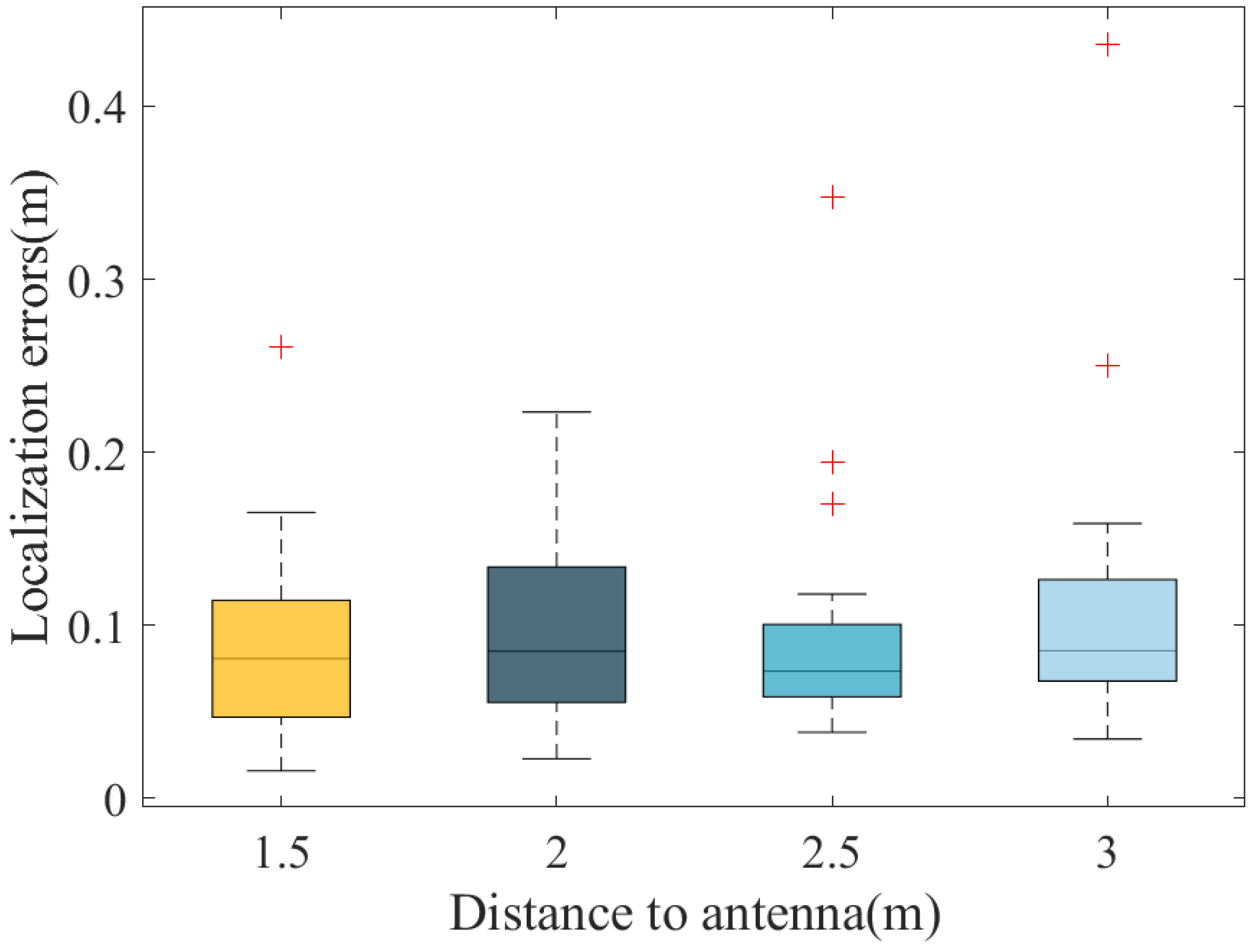
5.2.4. Reader Distance to Shelves

Following that, we adjusted the separation of the reader antenna and the shelf from 1.5 m to 3 m. The increase of the distance between the tags and the antennas decreases the received signal strength (RSS), the results are plotted in Figure 10. We discovered that the localization accuracy of DNCL increases as the above distance increases, and the localization effect is stable. This indicates that our proposed algorithm has good stability in the environment of multipath interference.

5.3. Evaluation

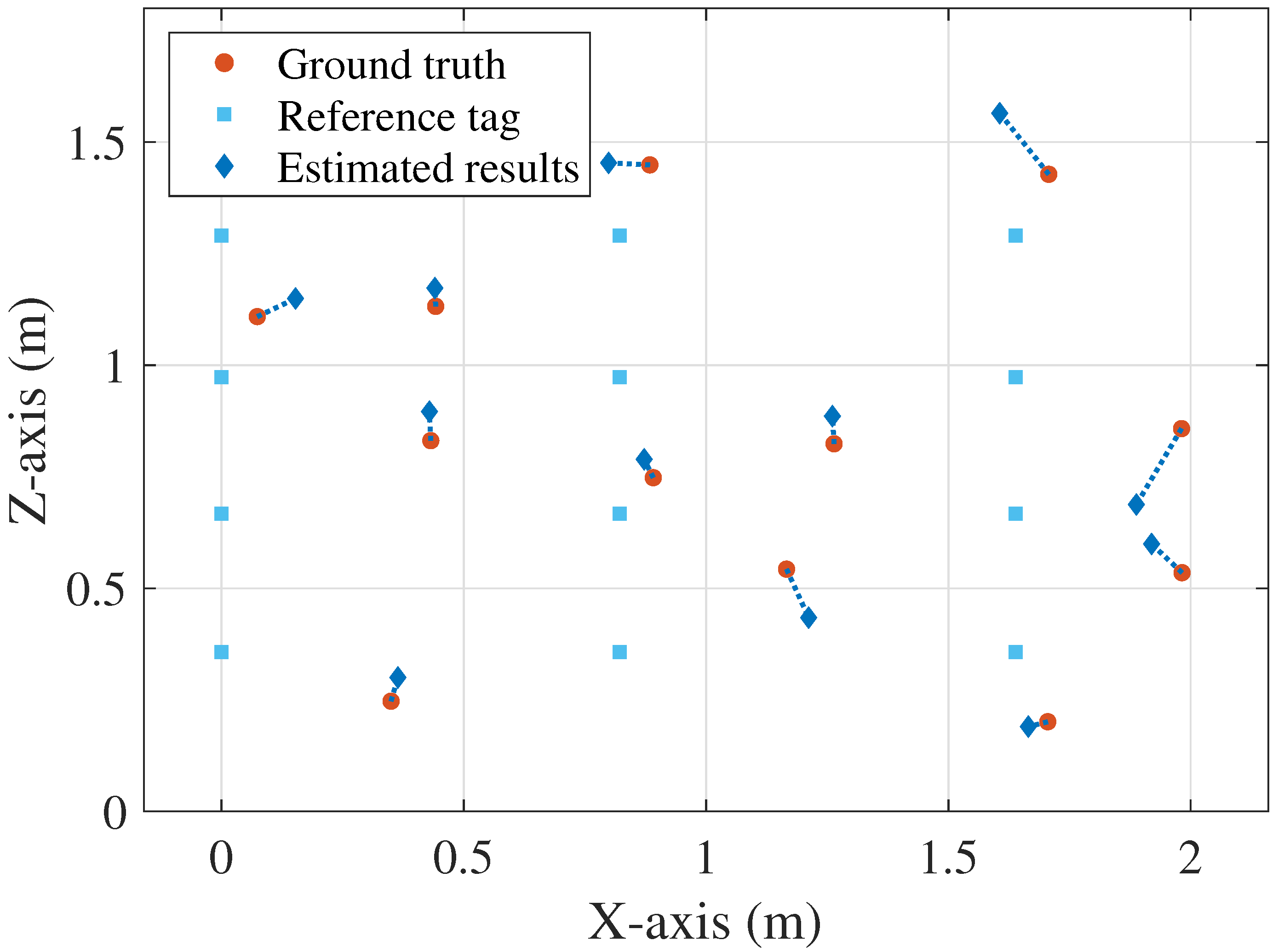
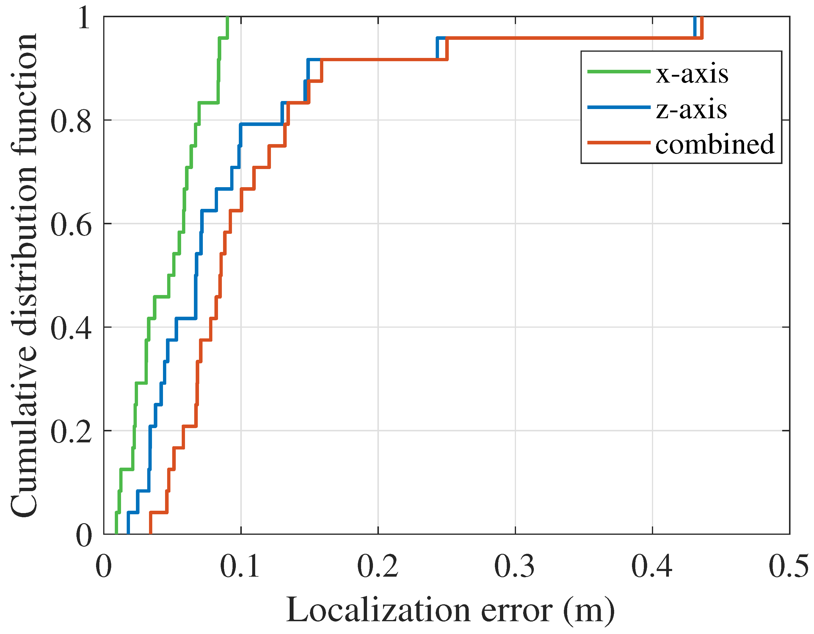
5.3.1. Method Performance

After determining the key system parameters, we evaluated the performance of the DNCL algorithm. Figure 6 shows the experimental layout. The antenna travels along the guide rail. The distance between the guide rail and the shelf is 2.5 m, and 12 reference tags are evenly arranged on the shelf. The results of the figurative localization of the tags are shown in Figure 11. To show the localization accuracy more intuitively, we marked the actual positions of the reference tags and tags to be measured on the figure. Meanwhile, as shown in Figure 12, the cumulative distribution function (CDF) curves of the proposed algorithm for the localization scenarios in x-axis up, z-axis up, and overall, with median localization errors of 4.73 cm, 6.76 cm, and 8.47 cm, respectively. In general, based on the localization effect in the figure, our proposed method can distinguish tags on different levels and columns of the shelf without ambiguity.

5.3.2. Comparison with Other Algorithms

There are many well-known state-of-the-art research approaches for RFID-based indoor localization. Table 1 shows a comparison of the proposed method (DNCL) with other five advanced methods (SARFID, STPP, Tagoram, ReLoc, HyLoc) in terms of system deployment and localization performance. Since we focused on RFID-based mobile platforms for automated warehouse management scenarios, the entire complexity on the system ought to be under consideration.
All of the comparative methodologies listed in the table are based on COTS RFID devices. STPP and HyLoc utilize one antenna, although they all achieve just single-axis-up localization for the item. SARFID, Tagoram, and ReLoc all employ two commercial antennas. ReLoc requires setting the tilt angle and space between the antennas and the shelf, distinguishing the horizontal order on the basis of the RSS difference between the two tilted antennas, and using the phase information for lateral localization. The experimental equipment deployment is relatively complex. The STPP algorithm generates phase profiles for individual tag using mobile antennas and directly estimates the sequence of tags by the exploration of the spatio-temporal correlation of the phase profiles, which requires a comparative reference based on the phase profiles of neighboring tags. Both SARFID and Tagoram are based on coordinate systems. They get absolute locations by employing phase information to create holograms that pinpoint the coordinates of the tags. Tagoram further proposed differential augmented holograms, but they both require multiple antennas for phase reading. HyLoc uses the distance difference obtained from the phase difference to transform the positioning problem into the solution of hyperbolic equations, which can only achieve localization when the tags and antenna are positioned on the same two-dimensional plane. In contrast, our method based on the tag phase information obtained from a simple one-dimensional scan using a single antenna could achieve spatial coordinate localization of tagged objects. To conclude, our method is more suitable for COTS RFID devices in mobile scenarios than other systems.

6. Conclusions

In this paper, we propose the DNCL system, based on hybrid direction-of-arrival estimation and nonmetric multidimensional scaling for RFID localization. DNCL uses the tag phase information obtained from a simple 1D scan performed by a single antenna to achieve spatial coordinate localization of tagged objects. The virtual antenna array performs rank-recovery DOA estimation for the acquired phase information. We propose determining the characteristics of each tag using a linear model of the angle profile and introduced the NMDS algorithm to achieve spatial localization with high accuracy and strong robustness. The results of the series of experiments were performed in the indoor environment and showed that the proposed method can achieve high accuracy positioning of passive tags. Looking ahead, we will attempt to further improve the method for practical application of DNCL to solve more complex situations and hope that our work can be applied to warehouse management-related industries.

Author Contributions

Conceptualization, Y.M.; methodology, Y.L., C.T.; software, Y.L.; validation, Y.M., Y.L. and D.S.; investigation, Y.L., C.T.; writing—original draft preparation, Y.L.; writing—review and editing, Y.M., B.Y. All authors have read and agreed to the published version of the manuscript.

Funding

This work is supported by Natural Science Foundation of China under Grant 61972279 and Tianjin Natural Science Foundation (No. 20JCYBJC00860).

Conflicts of Interest

The authors declare no conflict of interest.

References

  1. Kuutti, S.; Fallah, S.; Katsaros, K.; Dianati, M.; Mccullough, F.; Mouzakitis, A. A Survey of the State-of-the-Art Localization Techniques and Their Potentials for Autonomous Vehicle Applications. IEEE Internet Things J. 2018, 5, 829–846. [Google Scholar] [CrossRef]
  2. Altaf, S.; Haroon, M.; Ahmad, S.; Nasr, E.A.; Zaindin, M.; Huda, S. Radio-Frequency-Identification-Based 3D Human Pose Estimation Using Knowledge-Level Technique. Electronics 2023, 12, 374. [Google Scholar] [CrossRef]
  3. Zafari, F.; Gkelias, A.; Leung, K.K. A survey of indoor localization systems and technologies. IEEE Commun Surv. Tutor. 2019, 21, 2568–2599. [Google Scholar] [CrossRef] [Green Version]
  4. Kunhoth, J.; Karkar, A.; Al-Maadeed, S.; Al-Ali, A. Indoor positioning and wayfinding systems: A survey. Hum.-Centric Comput. Inf. Sci. 2020, 10, 1–41. [Google Scholar] [CrossRef]
  5. Xiong, J.; Jamieson, K. ArrayTrack: A Fine-Grained Indoor Location System. In Proceedings of the Proceedings USENIX Symposium on Networked Systems Design and Implementation (NSDI), Lombard, IL, USA, 2–5 April 2013; pp. 71–84. [Google Scholar]
  6. Kotaru, M.; Joshi, K.; Bharadia, D.; Katti, S. Spotfi: Decimeter level localization using wifi. In Proceedings of the Proceedings ACM Conference Special Interest Group Data Commun, (SIGCOMM), London, UK, 17–21 August 2015; pp. 269–282. [Google Scholar]
  7. Luo, Y.; Law, C.L. Indoor Positioning Using UWB-IR Signals in the Presence of Dense Multipath with Path Overlapping. IEEE Trans. Wirel. Commun. 2012, 11, 3734–3743. [Google Scholar] [CrossRef]
  8. Tiemann, J.; Wietfeld, C. Scalable and precise multi-UAV indoor navigation using TDOA-based UWB localization. In Proceedings of the International Conference on Indoor Positioning and Indoor Navigation (IPIN), Sapporo, Japan, 18–21 September 2017; pp. 1–7. [Google Scholar] [CrossRef]
  9. Li, C.; Mo, L.; Zhang, D. Review on UHF RFID Localization Methods. IEEE J. Radio Freq. Identif. 2019, 3, 205–215. [Google Scholar] [CrossRef]
  10. Jiang, Y.; Ma, Y.; Liu, H.; Zhang, Y. RF-SML: A SAR-based multi-granular and real-time localization method for RFID tags. Electronics 2020, 9, 1447. [Google Scholar] [CrossRef]
  11. Costanzo, A.; Masotti, D.; Ussmueller, T.; Weigel, R. Tag, You’re It: Ranging and Finding via RFID Technology. IEEE Microw. Mag. 2013, 14, 36–46. [Google Scholar] [CrossRef]
  12. Arthaber, H.; Faseth, T.; Galler, F. Spread-Spectrum Based Ranging of Passive UHF EPC RFID Tags. IEEE Commun. Lett. 2015, 19, 1734–1737. [Google Scholar] [CrossRef]
  13. Ussmueller, T.; Brenk, D.; Essel, J.; Heidrich, J.; Fischer, G.; Weigel, R. Roundtrip-Time-of-Flight based localization of passive multi-standard RFID-tags. In Proceedings of the 2012 IEEE International Conference on Wireless Information Technology and Systems (ICWITS), Maui, Hawaii, 11–16 November 2012; pp. 1–4. [Google Scholar] [CrossRef]
  14. Ni, L.; Liu, Y.; Lau, Y.C.; Patil, A. LANDMARC: Indoor location sensing using active RFID. In Proceedings of the First IEEE International Conference on Pervasive Computing and Communications, (PerCom), Fort Worth, TX, USA, 23–26 March 2003; pp. 407–415. [Google Scholar] [CrossRef]
  15. Zhang, J.; Lyu, Y.; Patton, J.; Periaswamy, S.C.G.; Roppel, T. BFVP: A Probabilistic UHF RFID Tag Localization Algorithm Using Bayesian Filter and a Variable Power RFID Model. IEEE Trans. Ind. Electron. 2018, 65, 8250–8259. [Google Scholar] [CrossRef]
  16. Shangguan, L.; Li, Z.; Yang, Z.; Li, M.; Liu, Y.; Han, J. OTrack: Towards Order Tracking for Tags in Mobile RFID Systems. IEEE Trans. Parallel Distrib. Syst. 2014, 25, 2114–2125. [Google Scholar] [CrossRef]
  17. Ruan, W.; Yao, L.; Sheng, Q.Z.; Falkner, N.J.; Li, X. Tagtrack: Device-free localization and tracking using passive rfid tags. In Proceedings of the 11th Annual International Conference on Mobile and Ubiquitous Systems: Computing, Networking and Services, London, UK, 2–5 December 2014; pp. 80–89. [Google Scholar]
  18. Ur Rehman, S.; Liu, R.; Zhang, H.; Liang, G.; Fu, Y.; Qayoom, A. Localization of moving objects based on RFID tag array and laser ranging information. Electronics 2019, 8, 887. [Google Scholar] [CrossRef] [Green Version]
  19. Wang, J.; Vasisht, D.; Katabi, D. RF-IDraw: Virtual Touch Screen in the Air Using RF Signals. In Proceedings of the ACM Special Interest Group on Data Communication (SIGCOMM), SIGCOMM’14, New York, NY, USA, 10–14 September 2014; pp. 235–246. [Google Scholar] [CrossRef] [Green Version]
  20. Wang, J.; Xiong, J.; Jiang, H.; Chen, X.; Fang, D. D-Watch: Embracing “Bad” Multipaths for Device-Free Localization with COTS RFID Devices. IEEE/ACM Trans. Netw. 2017, 25, 3559–3572. [Google Scholar] [CrossRef]
  21. Yang, L.; Chen, Y.; Li, X.Y.; Xiao, C.; Li, M.; Liu, Y. Tagoram: Real-time tracking of mobile RFID tags to high precision using COTS devices. In Proceedings of the Annu Int Conf Mobile Comput Networking (MobiCom), Maui, HI, USA, 7–11 September 2014; pp. 237–248. [Google Scholar]
  22. Liu, T.; Liu, Y.; Yang, L.; Guo, Y.; Wang, C. BackPos: High Accuracy Backscatter Positioning System. IEEE Trans. Mob. Comput. 2016, 15, 586–598. [Google Scholar] [CrossRef]
  23. Ma, Y.; Fu, Y.; Liang, X.; Liu, H.; Chen, K. An Efficient Method for Hyperbolic-Based Localization in SAR RFID Systems. IEEE Trans. Instrum. Meas. 2022, 71, 1–12. [Google Scholar] [CrossRef]
  24. Nafi, K.W.; Gong, W.; Nayak, A. MuSLoc: Circular Array Based Indoor Localization with COTS APs. In Proceedings of the IEEE Int. Instrum. Meas. Technol. Conf. (I2MTC), Auckland, New Zealand, 20–23 May 2019; pp. 1–5. [Google Scholar] [CrossRef]
  25. Azzouzi, S.; Cremer, M.; Dettmar, U.; Kronberger, R.; Knie, T. New measurement results for the localization of UHF RFID transponders using an Angle of Arrival (AoA) approach. In Proceedings of the 2011 IEEE International Conference on RFID, Orlando, FL, USA, 12–14 April 2011; pp. 91–97. [Google Scholar] [CrossRef]
  26. Alvarez-Narciandi, G.; Laviada, J.; Pino, M.R.; Las-Heras, F. Attitude Estimation Based on Arrays of Passive RFID Tags. IEEE Trans. Antennas Propag. 2018, 66, 2534–2544. [Google Scholar] [CrossRef]
  27. Cremer, M.; Dettmar, U.; Hudasch, C.; Kronberger, R.; Lerche, R.; Pervez, A. Localization of Passive UHF RFID Tags Using the AoAct Transmitter Beamforming Technique. IEEE Sens. J. 2016, 16, 1762–1771. [Google Scholar] [CrossRef]
  28. Duan, C.; Yang, L.; Lin, Q.; Liu, Y. Tagspin: High Accuracy Spatial Calibration of RFID Antennas via Spinning Tags. IEEE Trans. Mob. Comput. 2018, 17, 2438–2451. [Google Scholar] [CrossRef]
  29. Buffi, A.; Motroni, A.; Nepa, P.; Tellini, B.; Cioni, R. A SAR-Based Measurement Method for Passive-Tag Positioning with a Flying UHF-RFID Reader. IEEE Trans. Instrum. Meas. 2019, 68, 845–853. [Google Scholar] [CrossRef]
  30. Tripicchio, P.; Unetti, M.; D’Avella, S.; Buffi, A.; Motroni, A.; Bernardini, F.; Nepa, P. A Synthetic Aperture UHF RFID Localization Method by Phase Unwrapping and Hyperbolic Intersection. IEEE Trans. Autom. Sci. Eng. 2022, 19, 933–945. [Google Scholar] [CrossRef]
  31. Bernardini, F.; Buffi, A.; Fontanelli, D.; Macii, D.; Magnago, V.; Marracci, M.; Motroni, A.; Nepa, P.; Tellini, B. Robot-Based Indoor Positioning of UHF-RFID Tags: The SAR Method with Multiple Trajectories. IEEE Trans. Instrum. Meas. 2021, 70, 1–15. [Google Scholar] [CrossRef]
  32. Miesen, R.; Kirsch, F.; Vossiek, M. UHF RFID Localization Based on Synthetic Apertures. IEEE Trans. Autom. Sci. Eng. 2013, 10, 807–815. [Google Scholar] [CrossRef]
  33. Zhang, Y.; Xie, L.; Bu, Y.; Wang, Y.; Wu, J.; Lu, S. 3-Dimensional Localization via RFID Tag Array. In Proceedings of the IEEE International Conference on Mobile Ad Hoc and Sensor Systems, (MASS), Orlando, FL, USA, 22–25 October 2017; pp. 353–361. [Google Scholar] [CrossRef]
  34. Bu, Y.; Xie, L.; Gong, Y.; Liu, J.; He, B.; Cao, J.; Ye, B.; Lu, S. RF-3DScan: RFID-based 3D Reconstruction on Tagged Packages. IEEE Trans. Mob. Comput. 2021, 20, 722–738. [Google Scholar] [CrossRef]
  35. Li, C.; Tanghe, E.; Plets, D.; Suanet, P.; Hoebeke, J.; De Poorter, E.; Joseph, W. ReLoc: Hybrid RSSI- and Phase-Based Relative UHF-RFID Tag Localization with COTS Devices. IEEE Trans. Instrum. Meas. 2020, 69, 8613–8627. [Google Scholar] [CrossRef]
  36. Wang, J.; Katabi, D. Dude, Where’s My Card? RFID Positioning That Works with Multipath and Non-Line of Sight. In Proceedings of the ACM SIGCOMM 2013 Conference on SIGCOMM, Hong Kong, China, 12–16 August 2013; pp. 51–62. [Google Scholar] [CrossRef]
  37. Gao, Z.; Ma, Y.; Liu, K.; Miao, X.; Zhao, Y. An Indoor Multi-Tag Cooperative Localization Algorithm Based on NMDS for RFID. IEEE Sens. J. 2017, 17, 2120–2128. [Google Scholar] [CrossRef]
  38. Shang, Y.; Rumi, W.; Zhang, Y.; Fromherz, M. Localization from connectivity in sensor networks. IEEE Trans. Parallel Distrib. Syst. 2004, 15, 961–974. [Google Scholar] [CrossRef] [Green Version]
  39. Vivekanandan, V.; Wong, V.W. Ordinal MDS-Based Localization for Wireless Sensor Networks. In Proceedings of the IEEE Vehicular Technology Conference, Melbourne, Australia, 7–10 May 2006; pp. 1–5. [Google Scholar] [CrossRef]
  40. Cheung, K.; So, H. A multidimensional scaling framework for mobile location using time-of-arrival measurements. IEEE Trans. Signal Process. 2005, 53, 460–470. [Google Scholar] [CrossRef] [Green Version]
  41. Stojmenovic, I. Handbook of Sensor Networks: Algorithms and Architectures; John Wiley & Sons: Hoboken, NJ, USA, 2005; Volume 49. [Google Scholar]
  42. Buffi, A.; Nepa, P.; Lombardini, F. A Phase-Based Technique for Localization of UHF-RFID Tags Moving on a Conveyor Belt: Performance Analysis and Test-Case Measurements. IEEE Sens. J. 2015, 15, 387–396. [Google Scholar] [CrossRef]
  43. Shangguan, L.; Yang, Z.; Liu, A.X.; Zhou, Z.; Liu, Y. STPP: Spatial-Temporal Phase Profiling-Based Method for Relative RFID Tag Localization. IEEE/ACM Trans. Netw. 2017, 25, 596–609. [Google Scholar] [CrossRef]
Figure 1. Conceptual diagram of DNCL.
Electronics 12 01742 g001
Figure 2. Direction-of-arrival of the antenna array.
Electronics 12 01742 g002
Figure 3. Flow chart of hybrid DOA estimation and NMDS cooperative multi-target localization system.
Electronics 12 01742 g003
Figure 4. The direction of arrival of the tag with mobile scanning.
Electronics 12 01742 g004
Figure 5. Linear model of DOA parameters.
Electronics 12 01742 g005
Figure 6. The layout of the RFID localization system.
Electronics 12 01742 g006
Figure 7. DOA estimation window size selection.
Electronics 12 01742 g007
Figure 8. Interrogation interval selection.
Electronics 12 01742 g008
Figure 9. Number of reference tags selection.
Electronics 12 01742 g009
Figure 10. The distance from the shelves to reader antenna.
Electronics 12 01742 g010
Figure 11. The figurative localization result of the experiment scenario.
Electronics 12 01742 g011
Figure 12. CDF curve of localization error in different axes.
Electronics 12 01742 g012
Table 1. Comparison of the common RFID localization methods.
Localization SchemeNumber of AntennasInformationMethodSystem SettingDistance between Antennas and TagsLocalization Accuracy
SARFID [42]two antennasphaseHologram-basedcoordinate system1.95 m6.3 cm(X-axis)
STPP [43]one antennaphaseProximity-based0.3 mbelow 6 cm(X-axis)
Tagoram [21]four antennasphaseHologram-basedcoordinate system6.35 cm(X-axis)
ReLoc [35]two antennasphase & RSSIProximity-basedtilted angle & distance1.2 m7 cm(X-axis), 93.8%(level ordering)
HyLoc [23]one antennaphaseHyperbolic-basedcoordinate system0.5 m5.43 cm(X-axis)
DNCL (our proposal)one antennaphaseDOA-basedcoordinate system2.5 m4.73 cm(X-axis), 6.76 cm(Z-axis), 8.47 cm(combined)
Disclaimer/Publisher’s Note: The statements, opinions and data contained in all publications are solely those of the individual author(s) and contributor(s) and not of MDPI and/or the editor(s). MDPI and/or the editor(s) disclaim responsibility for any injury to people or property resulting from any ideas, methods, instructions or products referred to in the content.

