

Improved Repetitive Control for an LCL-Type Grid-Tied Inverter with Frequency Adaptive Capability in Microgrids

1
School of Electronic and Information, Zhongyuan University of Technology, Zhengzhou 451191, China
2
Department of Electronic and Computer Engineering, Ritsumeikan University, Kusatsu 525-8577, Japan
*
Author to whom correspondence should be addressed.
Electronics 2023, 12(7), 1736; https://doi.org/10.3390/electronics12071736
Submission received: 1 March 2023
/
Revised: 3 April 2023
/
Accepted: 3 April 2023
/
Published: 5 April 2023
(This article belongs to the Topic Power System Dynamics and Stability)
Abstract
:Repetitive control (RC), which can track any periodic signal with a known integer period with zero steady-state error, is widely used for current control of grid-tied inverters in microgrids. However, the inherent one fundamental period time delay, leads to poor dynamic performance. Furthermore, the performance of conventional RC (CRC) will degrade when operating at a high variation grid frequency. Therefore, this paper proposes a frequency adaptive improved RC (FA-IRC) for grid-tied inverters. The improved RC (IRC) consists of a repetitive controller with a modified internal model filter, plus a proportional controller. In comparison to the CRC, the IRC has a good dynamic response, because it provides a higher gain and a wider bandwidth at the resonant frequency. Moreover, to achieve the frequency adaptability of the IRC, a fractional delay, based on a finite impulse response (FIR) filter, is built into the IRC system, to ensure that the resonant frequency of the IRC is approximately equal to the actual grid frequency and harmonic frequency. Stability analysis and characteristic analysis of the FA-IRC system are reported in this paper. Simulations are conducted, to demonstrate the validity of the proposed method.
1. Introduction
Distributed power generation technologies using intermittent renewable energy sources, are an important means of solving energy problems and have therefore received extensive research [1,2]. As an important hub for energy conversion, the grid-tied inverter in the microgrid directly affects the stable and safe operation of the entire electrical energy system. Therefore, research on current harmonic suppression strategies for grid-tied inverters has received considerable attention [3].
Repetitive control (RC), based on the internal model principle (IMP), is widely used in inverter control, due to its advantage of high control accuracy, and it is particularly good at suppressing periodic disturbances, such as dead zones and periodic distortions in the output waveform, caused by non-linear rectifier loads or grid harmonics [4,5,6,7]. However, it has one fundamental period time delay. Furthermore, a repetitive controller can be equivalent to the sum of a negatively scaled term, an integral term, and a set of resonant controllers [8]. However, the negative proportional term will result in a slow transient response. To this end, researchers have proposed two methods to enhance the dynamic response of RC systems, one is to enable the system to have a higher RC gain and to increase the error convergence rate, by applying accurate phase compensation to the RC [9,10]. The other is to combine RC with a feedback control with fast dynamic response, typically in cascade or parallel, with a proportional or proportional-integral control, to form a composite control [11,12]. In [12], a proportional integral multi resonant-type RC (PIMR-RC), combining a repetitive controller and a proportional item, was proposed for control of grid-tied inverters, to enhance the transient response. This method has the benefit of a clearer design concept and improved low-frequency harmonic suppression performance.
The digital representation of the CRC is given by the formula , where N is the order of RC and represents the proportion of the sampling frequency to the fundamental frequency. is typically a constant less than 1 or a zero-phase low-pass filter, to ensure a safe stability margin. In [13], a robust RC, based on a modified filter, was proposed, to obtain the performance improvement at the fundamental frequency. By utilizing this approach, it is possible to achieve a higher gain and a wider control bandwidth at the fundamental frequency, without the need for extensive computational resources. The wider bandwidth, implies that grid frequency variation in a small range (such as ±0.2 Hz) does not significantly impact performance, which is suitable for control of the active power filter [14].
However, the N value in RC is usually rounded up or down when the grid frequency varies in a large range in distributed power generation systems. Consequently, the control gain of each harmonic will decline as the resonant frequency of the RC deviates from harmonic frequencies, resulting in harmonic suppression performance degrading and the total harmonic distortion (THD) increasing.
There are four main methods used to improve the frequency adaptation of RC: variable sampling frequency RC [15,16], bandwidth RC [17,18], higher-order RC (HORC) [19], and fractional-order RC (FORC) [20,21,22,23]. A scheme proposed in [15] ensures an integer RC order by changing the sampling rate, but real time changing of the sampling frequency increases the complexity of the controller implementation. In [16], a spatial RC based on the phase angle information of the grid voltage was proposed, which enables a guaranteed constant number of samples per cycle. It achieves a fixed number of samples per cycle, but the price paid is the inherent problem with the variable sampling method. Ref. [18] proposed a multi-bandwidth RC to resist the grid frequency variation in a grid-tied inverter. It sets each resonant bandwidth individually, and is implemented as a linear phase finite impulse response (FIR) filter, but the realization of the internal model filter is still complex. Using the HORC system, multi-cycle errors are accumulated. Compared to CRC, HORC can reduce interference at intermediate frequencies or against changes in the frequency of periodic signals [24]. However, on the other hand, this makes the system design more complex and computationally burdensome.
For frequency adaptability of the RC, the fractional-order RC (FORC) has been presented in many studies, which uses the fractional delay (FD) filter to approach the fractional order. The FORC with fractional delay Lagrange-interpolation-based FIR filter, has been proposed in a variety of applications [25,26,27]. In addition, in [28], a Thiran infinite impulse response (IIR) filter was proposed, to approximate the FD to enhance the frequency adaptability of CRC. Generally, the IIR filter has a full amplitude gain of one and requires only phase design, but it has poles, and the overall stability must be considered when designing the system, whereas with the FIR filter, stability issues do not need to be considered and it can be used directly. Nevertheless, the above fractional-order repetitive control using the FIR filter is CRC-based.
Therefore, this paper proposes a frequency adaptive improved RC (FA-IRC), to enhance the performance of a grid-tied inverter at grid frequency fluctuations. The control strategy is based on a novel improved repetitive control. The proposed IRC effectively increases the RC gain and resonance bandwidth at frequencies of interest, by introducing a positive proportional gain and a modified internal model filter repetitive controller, which speeds up the dynamic response time. Moreover, to further improve the frequency adaptation capability, the Lagrange interpolating-polynomial-based FIR filter is used to approximate the fractional part of the order of the IRC. Therefore, the proposed FA-IRC not only offers better dynamic performance, but also a lower THD when the grid frequency fluctuates.
The remainder of this article is organized as follows. An LCL-type grid-tied inverter system is introduced in Section 2. In Section 3, characteristics of the CRC, the PIMR-RC, and the proposed IRC are demonstrated. In Section 4, the FA-IRC with the FIR filter is established. The realization of fractional delay using an FIR filter is given. Moreover, a stability analysis and characteristic analysis of the FA-IRC system are performed. Section 5 discusses the simulation results that demonstrate the theoretical analysis’s validity. Finally, conclusions are drawn in Section 6.
2. Grid-Tied Inverter System Modeling
Grid-tied inverters are widely used in microgrid distributed power generation systems. To prevent excessive harmonics, some filter topologies are proposed for grid-tied inverters. LCL filters have been used in place of L filters, to smooth the injected current with higher attenuation and reduction in size and weight of the components [29,30]. The impedance of the LLCL filter is almost zero at the switching frequency and therefore attenuates harmonic currents around the switching frequency [31]. The LLCL filter configuration simplifies the current control structure into single-loop current control, without extra damping loops. Nevertheless, extra control techniques are required to achieve active harmonic elimination.
Figure 1 shows an LCL-type single-phase grid-tied inverter control system [20]. In fact, the stability of a grid-tied inverter depends on the ratio of the grid impedance to the inverter impedance [32]. The stability of the internal current control loop of the individual inverter itself, in this paper, is related to the inherent LCL-filter resonance peak. To suppress the resonance peak of the LCL filter, a passive damping resistance is employed. In Figure 1, PWM is an acronym for pulse width modulation, which is a commonly used control technique in power electronics, automatic control, and communication fields. It adjusts the width of the control signal’s pulse, to control circuits or devices. ZOH stands for zero-order holder, which is a method for converting analog signals to digital signals. The phase-locked loop (PLL) is used to generate a signal whose phase is locked to the phase of the grid voltage at the point of common coupling (PCC). represents the output voltage of the inverter bridge, represents the grid equivalent inductance, represents the tracked reference current, represents the grid current, and represents the grid voltage.
The equivalent resistance is ignored, and the transfer function from the input voltage to the grid current is
The plant consists of a combination of inverter switches and the LCL filter, where the gain of the inverter switches is considered to be unity and the phase as zero degrees. Therefore, the LCL filter is considered as the plant. The system parameters are given in Table 1. According to Table 1 and (1), it can be written in discretization as
3. Improved RC
3.1. CRC
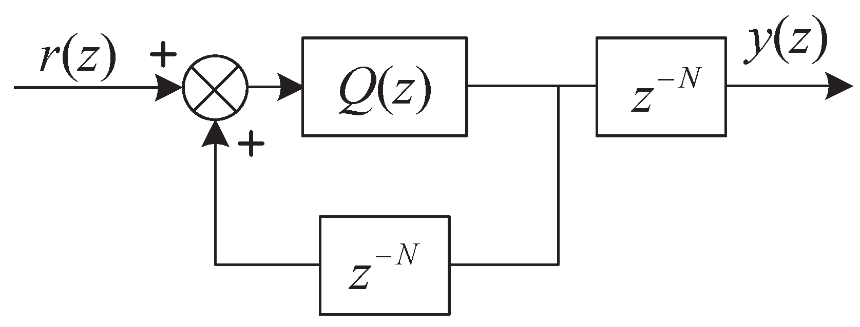
The block diagram of CRC is shown in Figure 2, it can be written as:
where and N are terms used in digital signal processing, with being an internal filter or a constant, and N representing the number of samples taken per cycle, with respect to the sampling frequency and the grid fundamental frequency . The transfer function of CRC in (3), can be derived as follows in the s-domain [8]:
where is the fundamental period of the reference signal, is the fundamental angular frequency, is the resonant bandwidth, and . It is clearly possible to see that the amplitude of is nearly infinite at angular frequency , indicating that CRC can achieve zero steady-state error tracking for periodic signals.
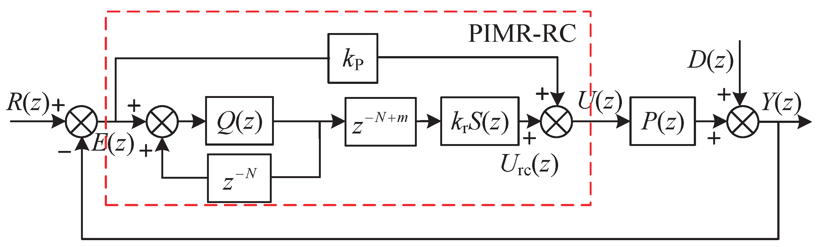
However, it can be seen from Figure 2 and (3), that the internal mode of CRC can be decomposed into a positive feedback link and a delayed link. The former is used to accumulate signal, which acts as an integrator for periodic signals. The latter, however, is used to delay the output of the signal by one cycle, leading to a deteriorating influence on system performance. Moreover, the equivalent negative proportional term in (4), will result in a slow transient response. Hence, a PIMR-RC with CRC combined with a proportional gain, is proposed, in order to address this issue. The block diagram of the PIMR-RC system is shown in Figure 3 [12].
In Figure 3, is the CRC gain, is the proportional gain, is the phase-lead compensator for the system delay caused by the plant and controller. is a low-pass filter that maintains system stability. is the plant, and is the disturbance. The transfer function from to can be written as
When = 1, the symbol of approximate equality in the above equation is valid, which is an advantageous frequency property for the RC design. In (5), provides CRC with a new plant [12]. In fact, can make the frequency response of close to 0 dB, and a suitably large enough can produce a larger range of , which can improve the dynamic response.
3.2. The Proposed IRC
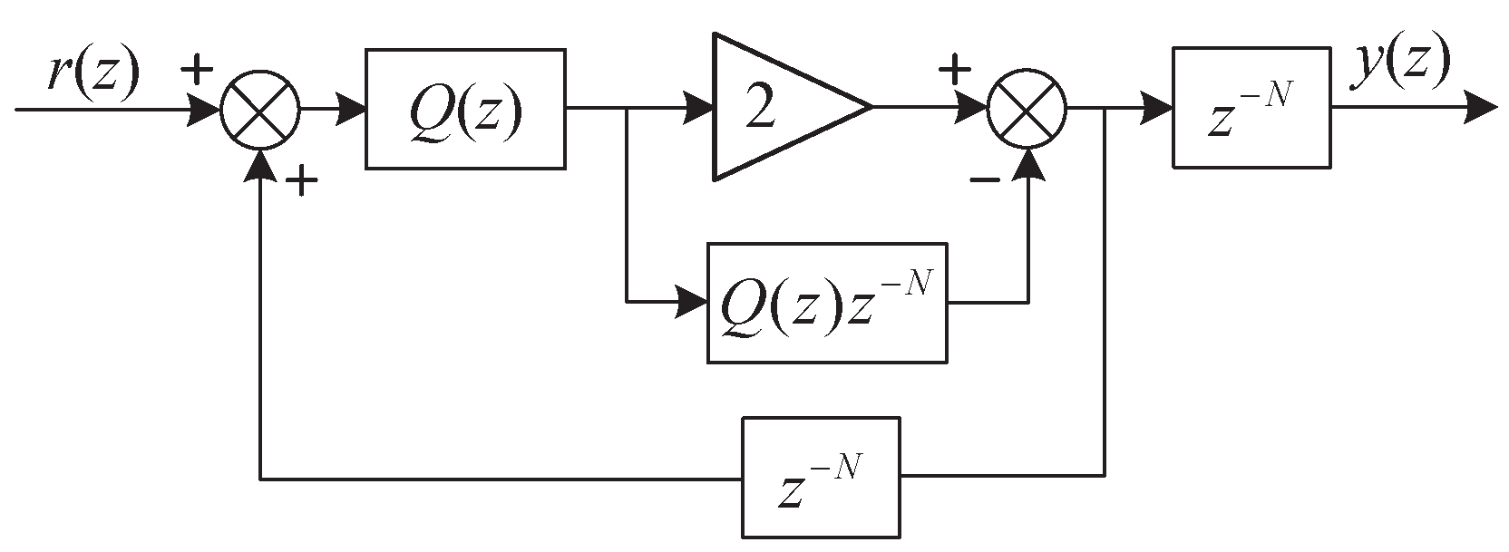
The proposed modified RC is shown in Figure 4, and the transfer function can be written as
where is the modified internal model filter.
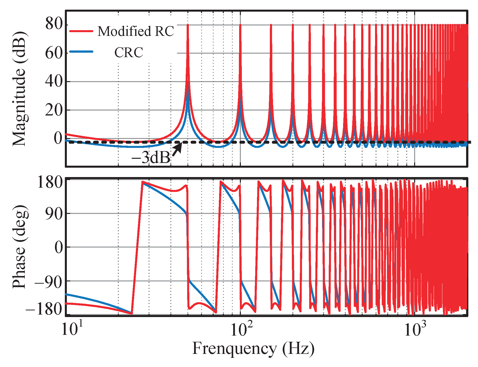
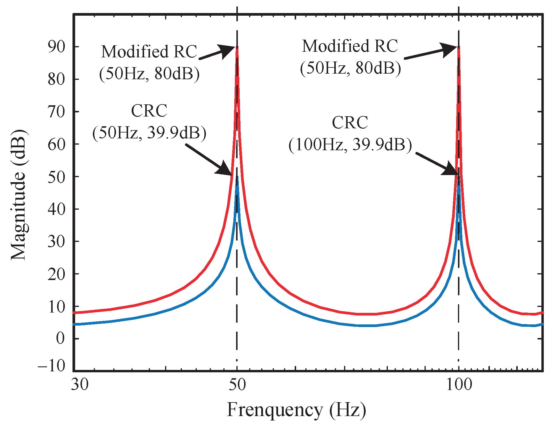
Figure 5 and Figure 6 show the frequency characteristics of the modified RC and CRC, when . As can be seen, at resonant frequencies, the modified RC has a greater gain than the CRC. Compared to CRC, the modified RC provides nearly twice the gain at 50 Hz and 100 Hz. Meanwhile, the resonant bandwidth of the modified RC is wider than CRC. Therefore, the modified RC has better harmonic rejection performance and the ability to resist frequency shifts.
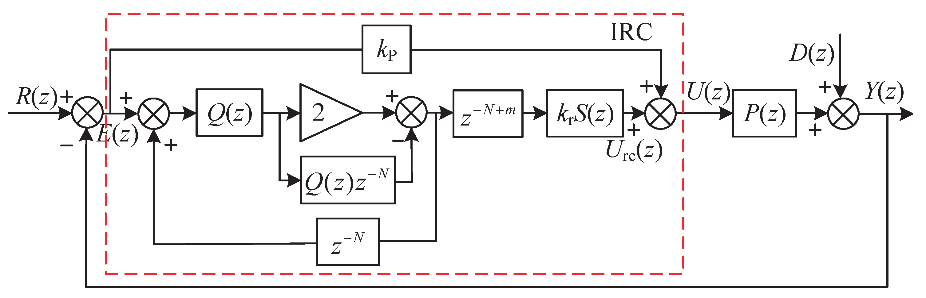
In reference to the PIMR-RC, the IRC is comprised of a modified RC and a proportional controller, as shown in Figure 7. The transfer function of the system can be written as [14]
where . By comparing (5) and (7), it is clear that is the square of the function in (5), so the amplitude of IRC with the modified filter structure, changes significantly. In fact, higher gain means a better harmonic rejection performance in this control system. However, the gain of the IRC also drops off severely when the grid fluctuates. Therefore, we need to ensure that its resonant frequency follows the grid frequency.
4. The Proposed Frequency Adaptive IRC
The grid frequency in the distributed power generation system may fluctuate [33], and may be a fraction. The values of N at different grid frequencies, when = 10 kHz, are shown in Table 2.
In this case, it is possible to divide N into an integer and a fraction D, as follows
4.1. Fractional Delay FIR Filter
The FIR filter approximates the fractional delay, using the following expression [34]
where M represents the filter order and represents the polynomial coefficient.
The coefficient , can be determined by the Lagrangian interpolation method, and is calculated as follows [34]
The best interpolation is achieved, when the interpolation point D, is close to the center of the sampled data, namely . In addition, a larger M can achieve higher accuracy, but the computational effort becomes larger. In this article, a third-order FIR filter is used. For example, when = 10 kHz, if changes to 49.6 Hz, then N = 201.6, can be expressed as . According to Table 3,
and
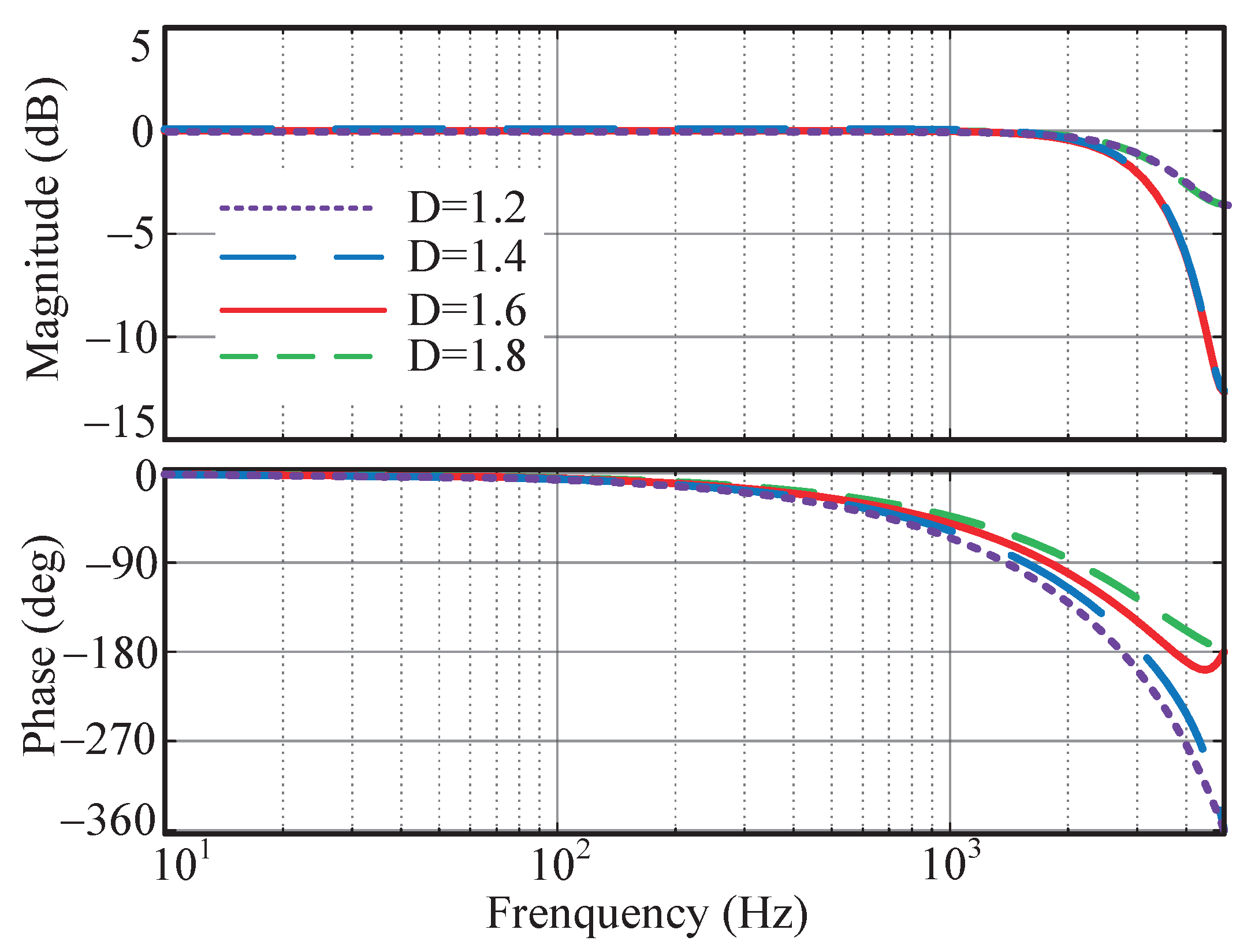
To obtain a high accuracy, the value of D is selected to be between 1.2 and 1.8 when the grid frequency varies. The frequency responses of FD filters based on Lagrangian interpolation, are shown in Figure 8 for different fractions of D, from 1.2 to 1.8, with order M = 3. The magnitude response of the FIR filter is close to one within the passband of the FD filter, which makes it possible to design repetitive controllers without considering the effect of the FIR on the system’s amplitude and frequency performance. In addition, its high frequency attenuation is more conducive to system stability. More importantly, the coefficients in the FD filter consume relatively little computational effort, so it is relatively simple to use Lagrangian interpolation to create an FD filter [36].
4.2. Stability Analysis of FA-IRC System
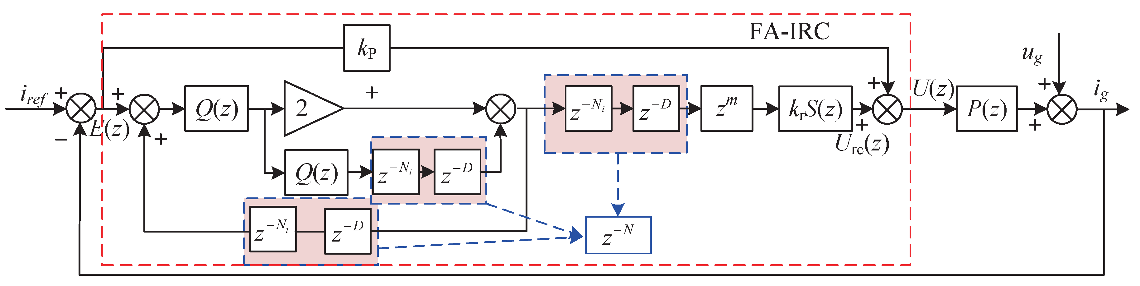
The structure diagram of the FA-IRC-based inverter control system is shown in Figure 9, where is the delay unit of FA-IRC. is the fractional delay based on the FIR filter. The transfer function from and to is
where
Thus, there are two stability conditions for the FA-IRC system:
- The roots of within the unit circle.
- .
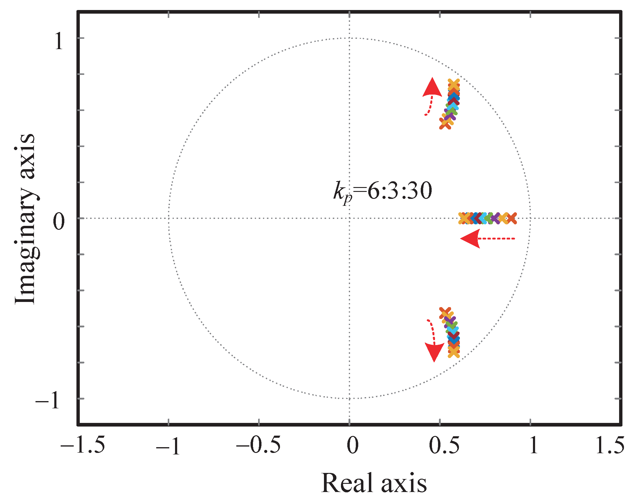
Obviously, the stability condition (1) is only related to the scale factor , and is therefore easier to satisfy. It means that the pole of (z) should lie within the unit circle. Figure 10 shows the distribution of the dominant poles of (z) with different . As can be seen, the stability condition (1) is satisfied when changes from 6 to 30.
Substitute (14) into condition (2),
If the frequency of reference signal and disturbance approach , with ( for even N and for odd N ), then [22]. Then, we have
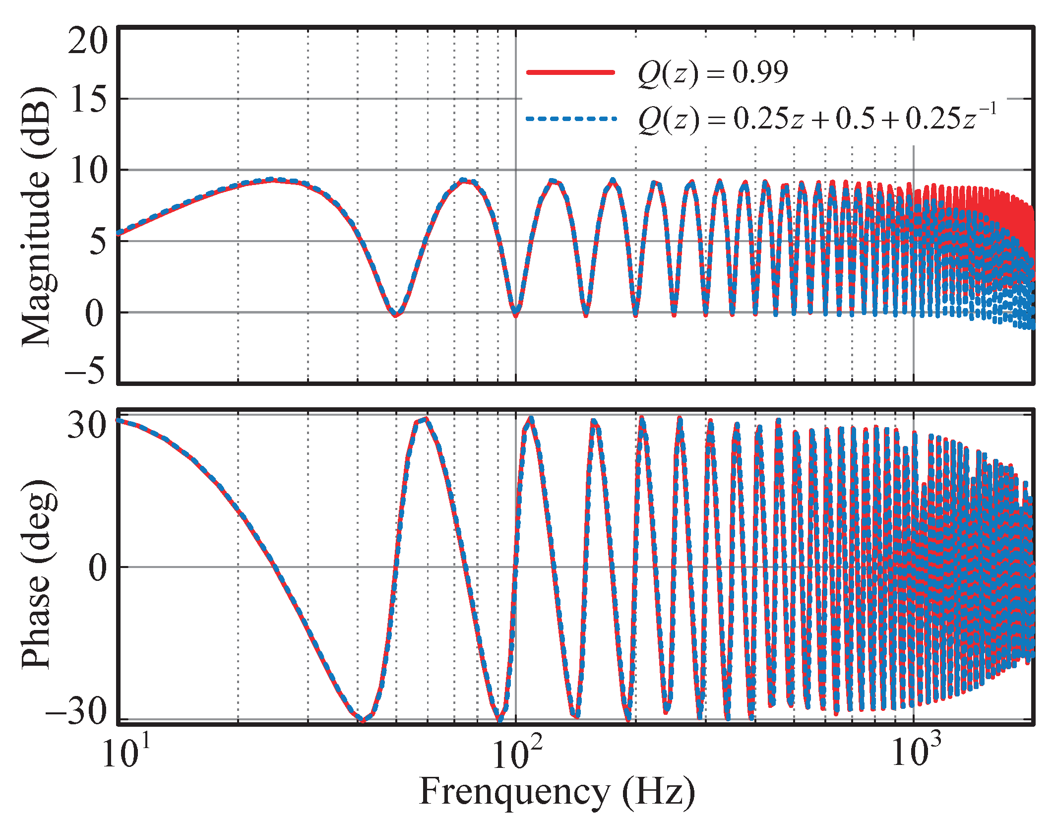
The Bode diagram of with and , is shown in Figure 11. It is obvious that the magnitude characteristic of is greater than 0, then (18) can be written as
Let , , and represent the magnitude characteristics of , , and , respectively, and , , and represent their phase characteristics. They can be written as follows
Then, (20) can be written as
According to Euler’s formula, since , , , and are also greater than 0. In order to maintain stability, the following conditions must be met
4.3. Characteristic Analysis
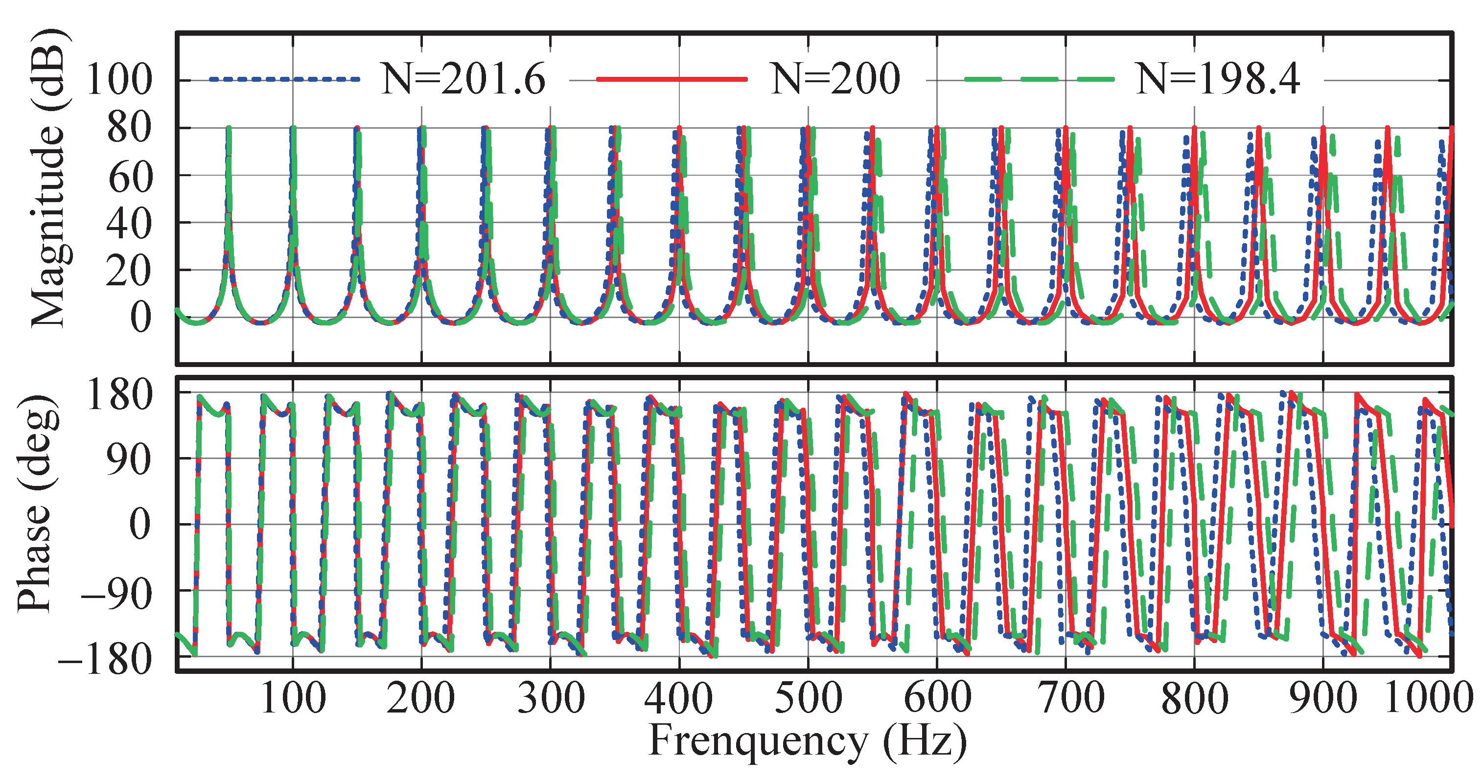
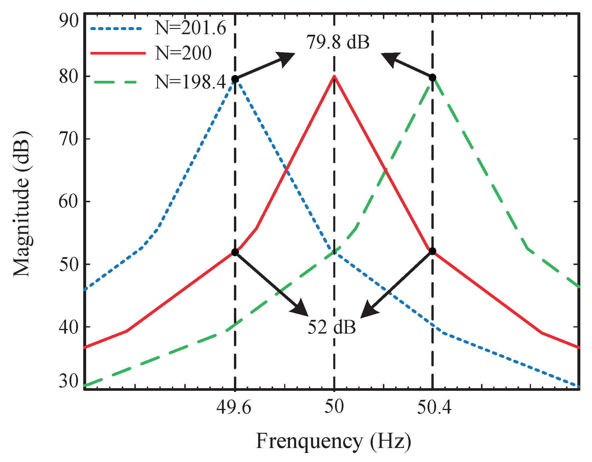
The Bode diagrams of the IRC and the FA-IRC under different N are shown in Figure 12. These show that, as the frequency increases, the deviation of the resonant frequency of the ideal IRC from the actual grid frequency and harmonic frequency, becomes larger. As a result, the reference signal tracking and harmonic rejection performance of the IRC degrades when the grid frequency fluctuates. Figure 13 describes the magnitude response around the fundamental frequency. It indicates that the amplitude of IRC is 79.8 dB at 50 Hz, whereas the amplitude of IRC decreases to 52 dB at 49.6 Hz and 50.4 Hz. While the FA-IRC’s resonant frequency can follow the actual frequency of the grid, it still has a large gain at 49.6 Hz and 50.4 Hz. This means that the FA-IRC can effectively eliminate harmonics when the grid frequency varies.
5. Simulation Verification
In order to verify the performance of the proposed FA-IRC, a single-phase inverter control system based on this method was built using MATLAB/Simulink. The parameters of this system are shown in Table 1. According to [12] and the analysis above, the parameters of FA-IRC were selected as follows: = 18, = 5, m = 8, , and the fourth-order Butterworth low-pass filter , with cutoff frequency 1 kHz, is as follows
For verifying the current tracking performance and the dynamic performance of the proposed FA-IRC, experimental results are compared with the CRC plus a proportional controller system (PIMR-RC system). In the PIMR-RC system, all control parameters remain fixed.
5.1. Steady State Response
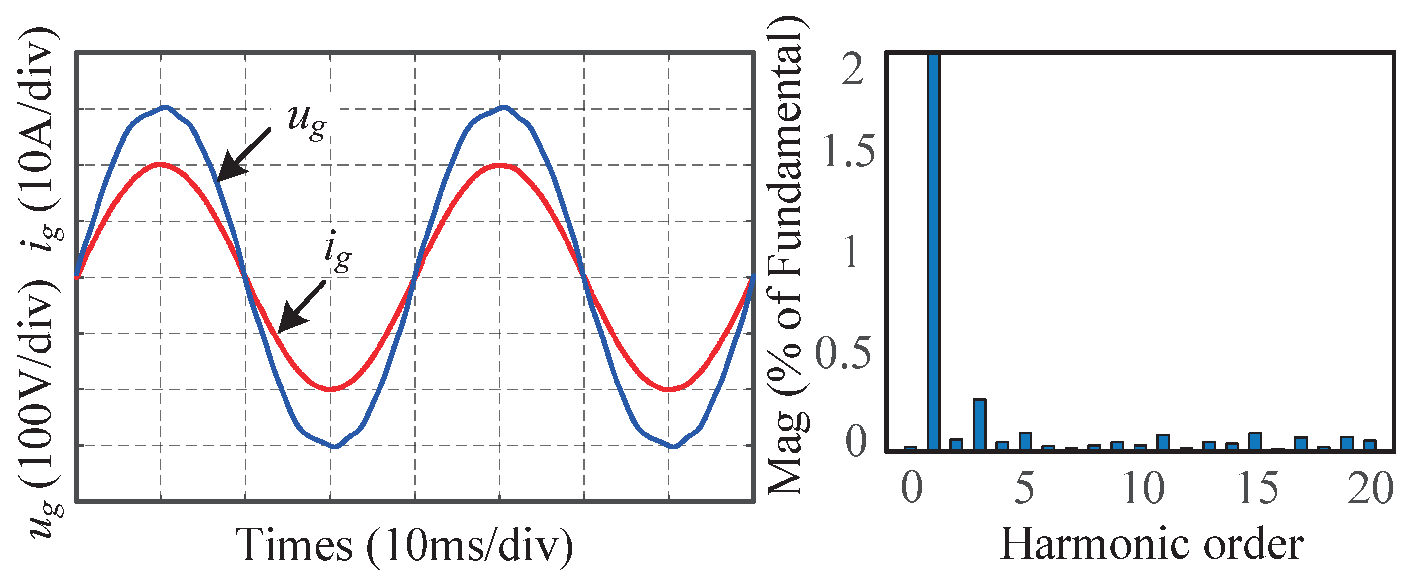
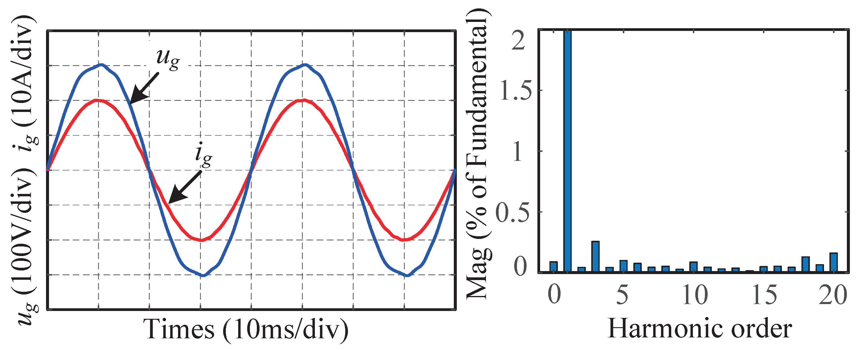
The steady-state response is examined under a reference current of 20 A amplitude. When is 50 Hz, the simulation results of the injected current , and grid voltage , under PIMR-RC are shown in Figure 14. The THD value of is 0.60%. In addition, the THD value of FA-IRC is 0.67% when is 50 Hz, as can be obtained from Figure 15. Clearly, both control systems are effective in suppressing harmonics when is 50 Hz.
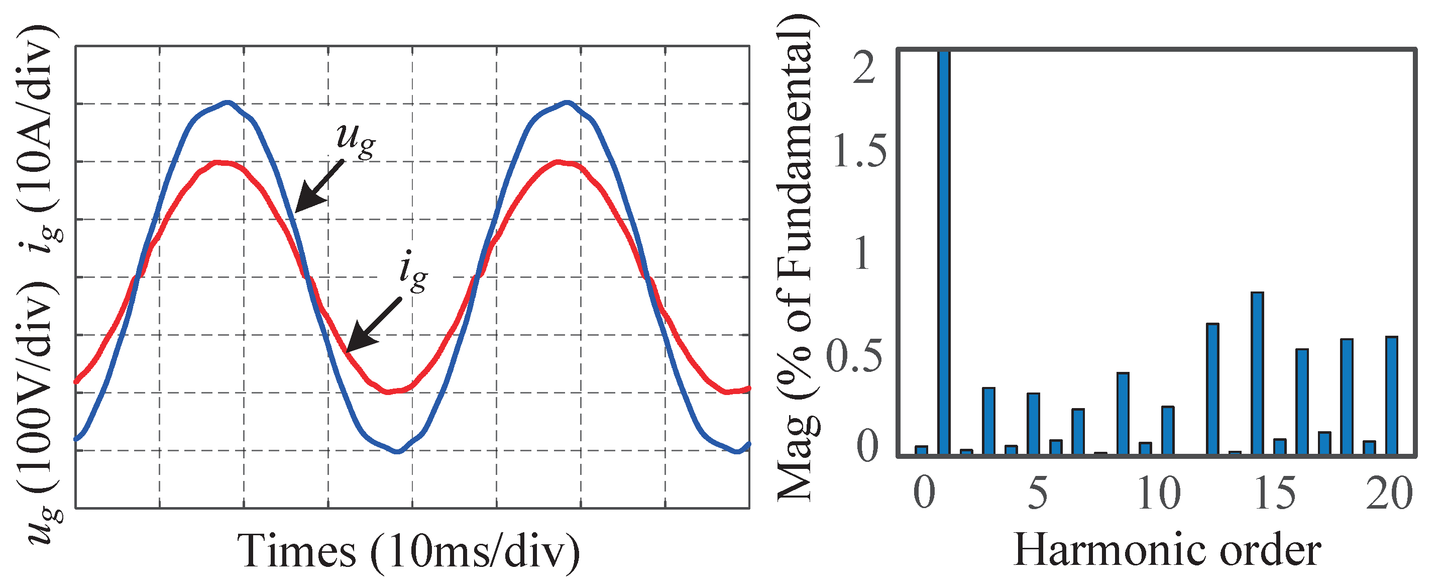
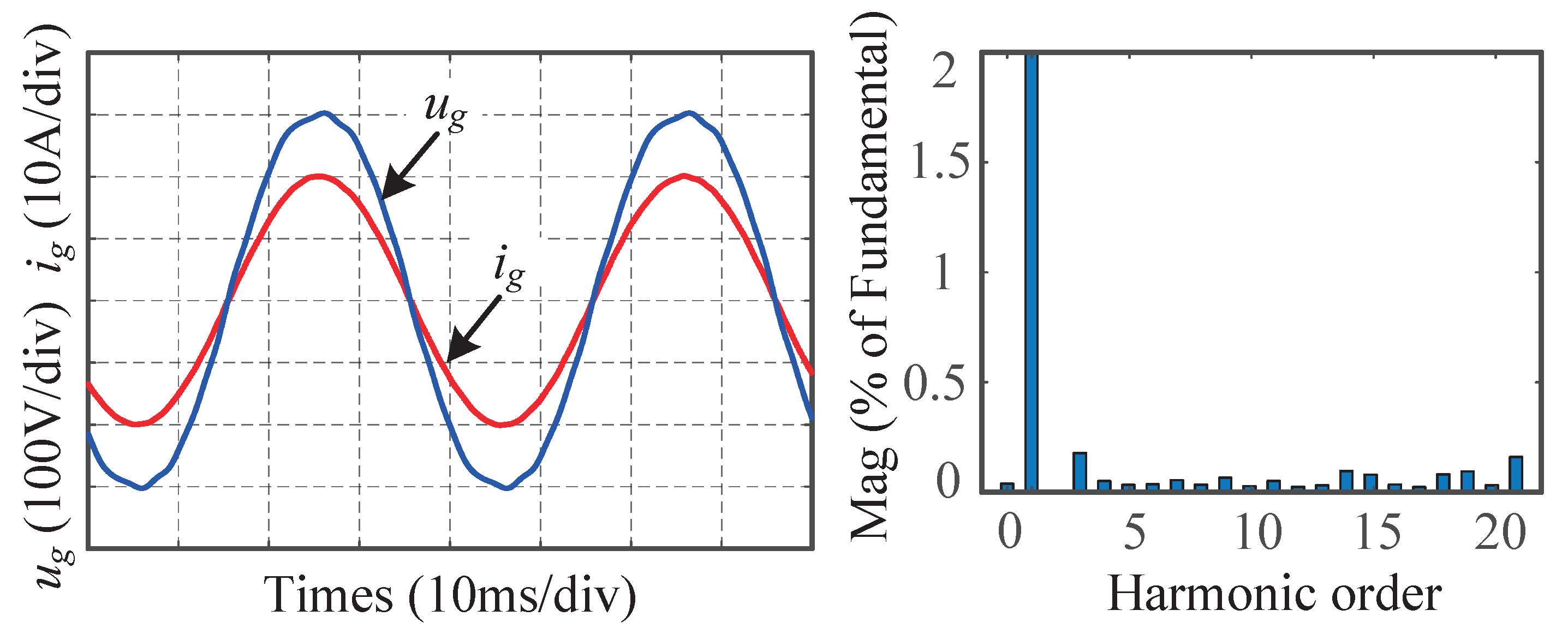
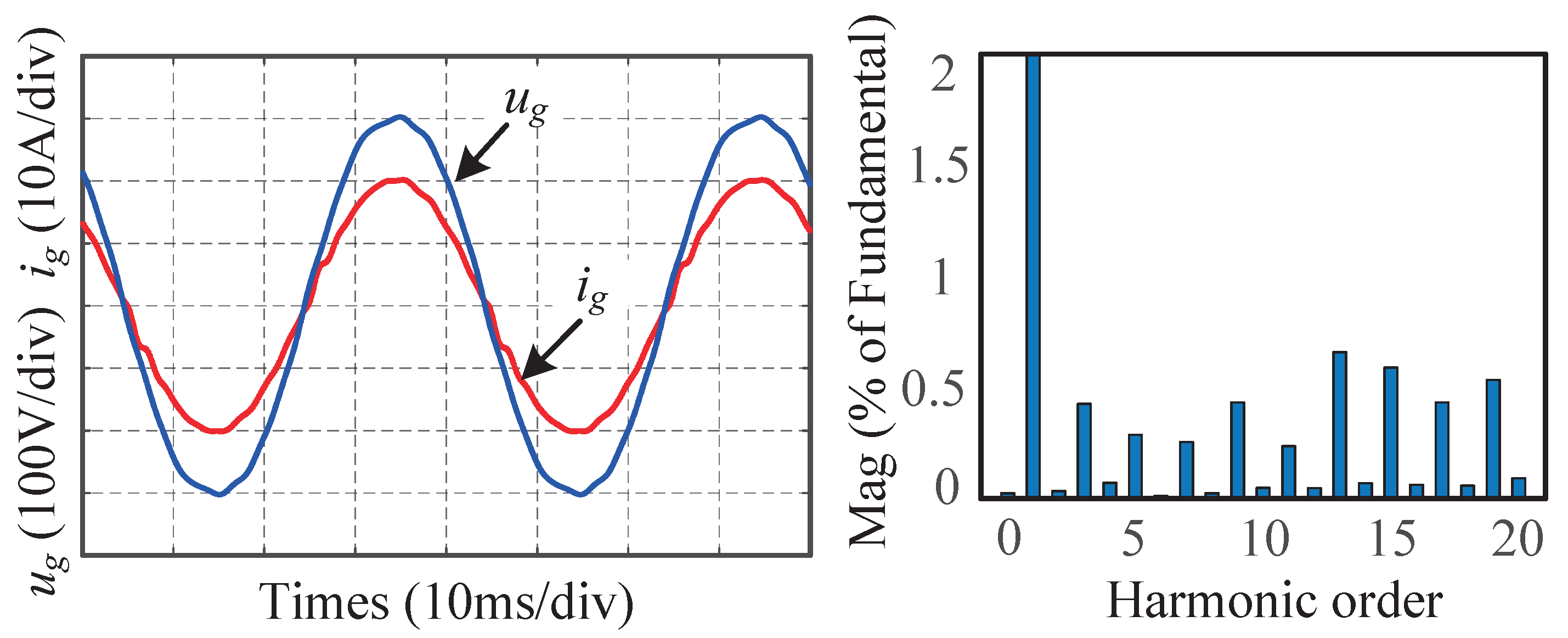
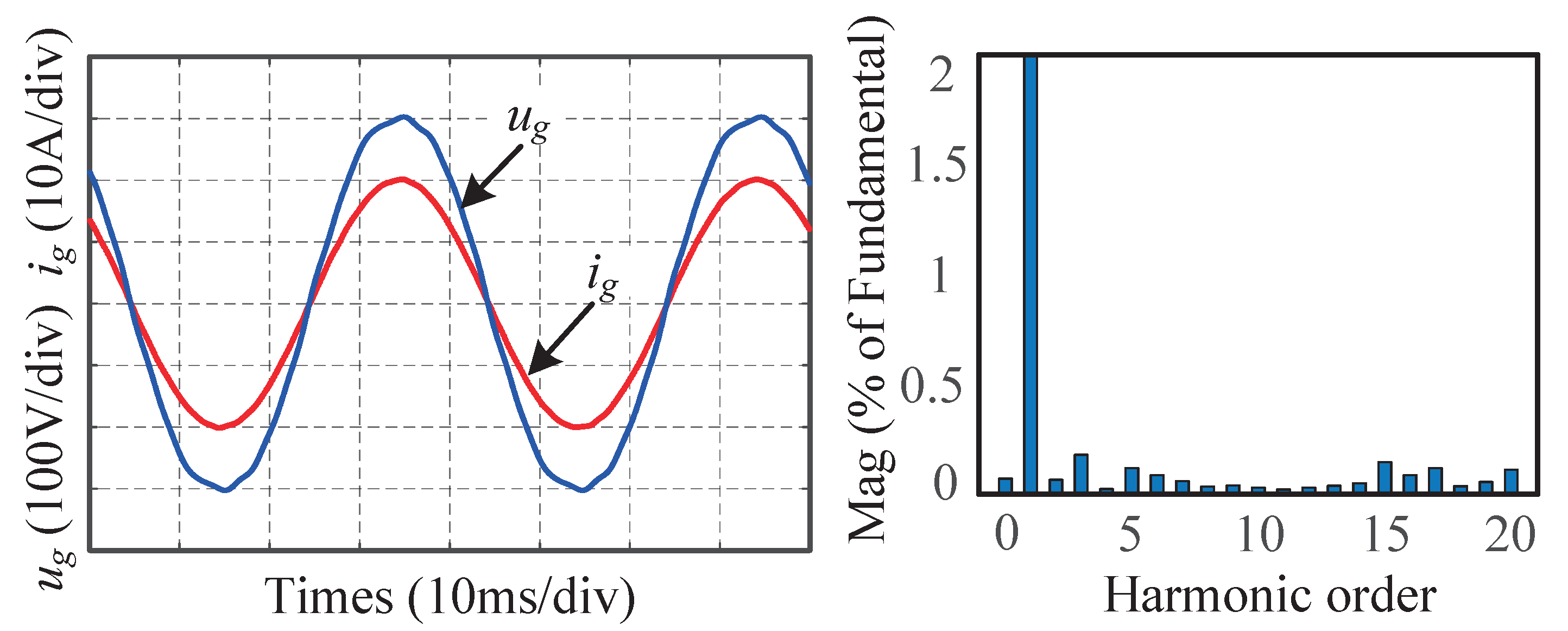
When is set at 49.6 Hz, PIMR-RC still takes the order of RC as 200, and the THD of increases to 1.70%, as shown in Figure 16. However, the THD value of under FA-IRC is 0.59%, as shown in Figure 17. The reason why this is the case, is that the resonant frequencies of FA-IRC are very close to the actual grid frequency and harmonic frequencies. Figure 18 and Figure 19 show similar results, to demonstrate the effectiveness of FA-IRC when the grid frequency is set at 50.4 Hz. The figures indicate that the THD of , with FA-IRC based on the FIR filter, is 0.70%, while it is 1.73% for with IRC.
In fact, the use of Thiran-based IIR fractional delay filter during grid frequency fluctuations has been proposed in many studies of frequency adaptation [20,28]. In order to validate the frequency adaptation of the proposed scheme, a frequency adaptive IRC, based on a second-order IIR filter, has been built. In addition, to verify the harmonic rejection capability of the RC, a quasi-proportional resonant (QPR) control system is added for comparison [37]. The parameters are selected as follows: , , and rad/s. The THD results of different control systems at different grid frequencies are summarized in Table 4. Table 4 indicates that the QPR control system is not affected by frequency variations, however, it has a higher THD compared to the RC based control system. In addition, it shows that the CRC and IRC systems are impacted by frequency changes to some extent. However, the proposed FA-IRC, and frequency adaptive IRC based on the IIR filter, maintain low THD values, due to their frequency adaptability.
5.2. Transient Response
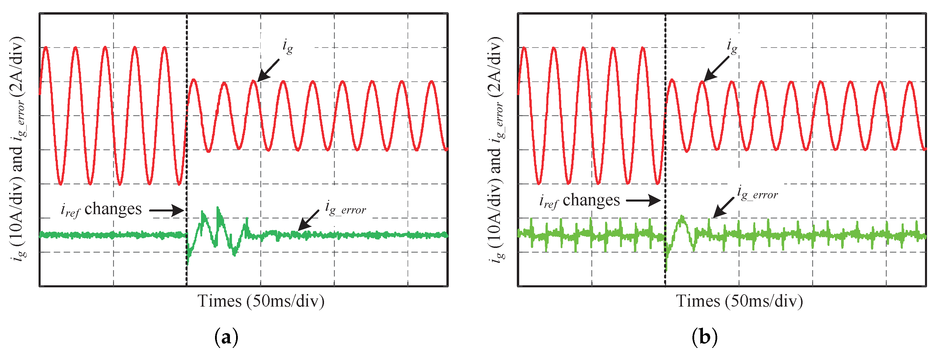
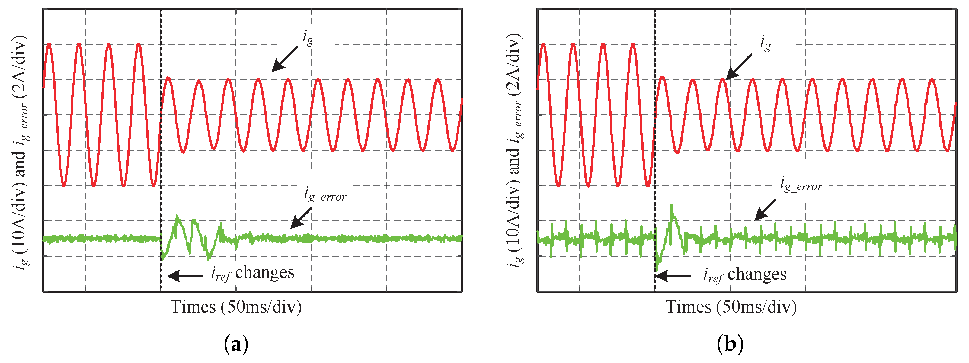
To verify the dynamic performance of the proposed FA-IRC, the transient response of reference current amplitude changes is illustrated. Figure 20 and Figure 21 give the transient waveforms and current error when the amplitude of drops from 20 A to 10 A, at different frequencies. The FA-IRC system can reach stability within 80 ms. Compared to the PIMR-RC system, the convergence rate of the FA-IRC system, with the same large gain, is equally fast. Furthermore, the current error of the FA-IRC system is approximately 0.04 A at grid frequencies of 49.6 Hz and 50.4 Hz, however, the current error of the PIMR-RC system is 0.2 A. Therefore, the proposed method can achieve good current tracking performance and dynamic performance when the grid frequency changes.
6. Conclusions
This paper proposes an FA-IRC with a fixed sampling rate, to reject the harmonic components in the injected current of grid-tied inverters when grid frequency varies. The control strategy is based on a novel improved repetitive control. The improved repetitive control, with a modified internal model filter and a positive proportional gain, has a higher gain and bandwidth at resonant frequencies. Therefore, it has good dynamic performance. Moreover, to achieve frequency adaptive capability, a fractional-order delay, based on a polynomial Lagrange interpolating FIR filter, is built into the system. The FA-IRC system can output high quality current when the grid fundamental frequency varies within ±0.4 Hz, because it makes the resonant frequency of the IRC approximate the actual grid frequency and harmonic frequency. Simulation results demonstrate that the FA-IRC is effective at resisting variations in grid frequency.
It is worth mentioning that, for the control methods of the grid-tied inverters considered in this paper, grid voltage magnitude fluctuations and grid impedance variations, which are common in distributed generation systems, are not taken into account. The impedance analysis method is an important tool for the stability of grid-tied inverter–grid interaction systems. It conveniently implements the modeling of the frequency characteristics of the grid-tied inverter system, and effectively simplifies the complexity of the grid-tied inverter system impedance stability analysis during grid changes. In addition, the inverter–grid system can be kept stable with reasonable grid voltage feedforward values. These cases should be considered in future work.
Author Contributions
Conceptualization, H.Z. and Q.Z.; methodology, H.Z.; investigation, H.Z., Q.Z., S.W. and X.Y.; writing—original draft preparation, H.Z.; writing—review and editing, H.Z., Q.Z., S.W. and X.Y.; supervision, H.Z. All authors have read and agreed to the published version of the manuscript.
Funding
This work was supported in part by the National Natural Science Foundation of China, under grant 61973157 and 62073297, in part by the Natural Science Foundation of Henan Province, under grant 232300421239, in part by the Science and Technology Innovation Team of Colleges and Universities in Henan Province, under grant 22IRTSTHN015, and in part by the Incubation Program for Young Master Supervisor of Zhongyuan University of Technology, under grant D202213.
Data Availability Statement
All data generated or analysed during this study are included in this published article.
Conflicts of Interest
The authors declare no conflict of interest.
Abbreviations
The following abbreviations are used in this manuscript:
| IRC | Improved repetitive control |
| RC | Repetitive control |
| CRC | Conventional repetitive control |
| HORC | Higher-order repetitive control |
| FA-IRC | Frequency adaptive improved repetitive control |
| FD | Fractional delay |
| FIR | Finite impulse response |
| IIR | Infinite impulse response |
| PIMR-RC | Proportional integral multi resonant-type repetitive control |
| IMP | Internal model principle |
| THD | Total harmonic distortion |
| PWM | Pulse width modulation |
| ZOH | Zero-order holder |
| PLL | Phase-locked loop |
| PCC | Point of common coupling |
| QPR | Quasi-proportional resonant |
References
- Abdullah, M.A.; Muttaqi, K.M.; Agalgaonkar, A.P. Sustainable energy system design with distributed renewable resources considering economic, environmental and uncertainty aspects. Renew. Energy 2015, 78, 165–172. [Google Scholar] [CrossRef]
- Seifi, K.; Moallem, M. Synchronization and control of a single-phase grid-tied inverter under harmonic distortion. Electronics 2023, 12, 860. [Google Scholar] [CrossRef]
- Yang, Y.; Zhou, K.; Blaabjerg, F. Current harmonics from single-phase grid-connected inverters—Examination and suppression. IEEE J. Emerg. Sel. Top. Power Electron. 2015, 4, 221–233. [Google Scholar] [CrossRef] [Green Version]
- Lunardi, A.; Conde, E.; Assis, J.; Meegahapola, L. Repetitive predictive control for current control of grid-connected inverter under distorted voltage conditions. IEEE Access 2022, 10, 16931–16941. [Google Scholar] [CrossRef]
- Peng, F.; Xie, W.; Yan, J. State feedback and deadbeat predictive repetitive control of three-phase Z-source inverter. Electronics 2023, 12, 1005. [Google Scholar] [CrossRef]
- Ramos, G.A.; Costa-Castelló, R. Comparison of different repetitive control architectures: Synthesis and comparison. application to VSI converters. Electronics 2018, 7, 446. [Google Scholar] [CrossRef] [Green Version]
- Jiang, S.; Cao, D.; Li, Y.; Liu, J.; Peng, F.Z. Low-THD, fast-transient, and cost-effective synchronous-frame repetitive controller for three-phase UPS inverters. IEEE Trans. Power Electron. 2012, 27, 2994–3005. [Google Scholar] [CrossRef]
- Yang, Y.; Zhou, K.; Cheng, M.; Zhang, B. Phase compensation multiresonant control of CVCF PWM converters. IEEE Trans. Power Electron. 2012, 28, 3923–3930. [Google Scholar] [CrossRef]
- Zhao, Q.; Ye, Y. Fractional phase lead compensation RC for an inverter: Analysis, design, and verification. IEEE Trans. Ind. Electron. 2016, 64, 3127–3136. [Google Scholar] [CrossRef]
- Chen, S.; Zhao, Q.; Ye, Y.; Qu, B. Using IIR filter in fractional order phase lead compensation PIMR-RC for grid-tied inverters. IEEE Trans. Ind. Electron. 2022, in press. [CrossRef]
- Wang, Y.; Darwish, A.; Holliday, D.; Williams, B.W. Plug-in repetitive control strategy for high-order wide-output range impedance-source converters. IEEE Trans. Power Electron. 2016, 32, 6510–6522. [Google Scholar] [CrossRef] [Green Version]
- Zhao, Q.; Ye, Y. A PIMR-type repetitive control for a grid-tied inverter: Structure, analysis, and design. IEEE Trans. Power Electron. 2017, 33, 2730–2739. [Google Scholar] [CrossRef]
- Kim, B.S.; Tsao, T.C. Robust repetitive controller design with improved performance. In Proceedings of the 2001 American Control Conference, Arlington, VA, USA, 25–27 June 2001; pp. 2027–2032. [Google Scholar]
- Pandove, G.; Singh, M. Robust repetitive control design for a three-phase four wire shunt active power filter. IEEE Trans. Ind. Informat. 2018, 15, 2810–2818. [Google Scholar] [CrossRef]
- Kurniawan, E.; Cao, Z.; Man, Z. Design of robust repetitive control with time-varying sampling periods. IEEE Trans. Ind. Electron. 2014, 61, 2834–2841. [Google Scholar] [CrossRef]
- Kolluri, S.; Gorla, N.B.Y.; Sapkota, R.; Panda, S.K. A new control architecture with spatial comb filter and spatial repetitive controller for circulating current harmonics elimination in a droop-regulated modular multilevel converter for wind farm application. IEEE Trans. Power Electron. 2019, 34, 10509–10523. [Google Scholar] [CrossRef]
- Song, Y.; Nian, H. Sinusoidal output current implementation of DFIG using repetitive control under a generalized harmonic power grid with frequency deviation. IEEE Trans. Power Electron. 2015, 30, 6751–6762. [Google Scholar] [CrossRef]
- Zhu, M.; Ye, Y.; Xiong, Y.; Zhao, Q. Multibandwidth repetitive control resisting frequency variation in grid-tied inverters. IEEE J. Emerg. Sel. Top. Power Electron. 2021, 10, 446–454. [Google Scholar] [CrossRef]
- Lu, W.; Wang, W.; Zhou, K.; Fan, Q. General high-order selective harmonic repetitive control for PWM converters. IEEE J. Emerg. Sel. Top. Power Electron. 2022, 10, 1178–1191. [Google Scholar] [CrossRef]
- Zhao, Q.; Zhang, H.; Gao, Y.; Chen, S.; Wang, Y. Novel fractional-order repetitive controller based on Thiran IIR filter for grid-connected inverters. IEEE Access 2022, 10, 82015–82024. [Google Scholar] [CrossRef]
- Escobar, G.; Hernandez-Gomez, M.; Valdez-Fernandez, A.A.; Lopez-Sanchez, M.J.; Catzin-Contreras, G.A. Implementation of a 6n ± 1 repetitive controller subject to fractional delays. IEEE Trans. Ind. Electron. 2015, 62, 444–452. [Google Scholar] [CrossRef]
- Yang, Y.; Zhou, K.; Wang, H.; Blaabjerg, F.; Wang, D.; Zhang, B. Frequency adaptive selective harmonic control for grid-connected inverters. IEEE Trans. Power Electron. 2015, 30, 3912–3924. [Google Scholar] [CrossRef] [Green Version]
- Zhao, Q.; Chen, S.; Wen, S.; Qu, B.; Ye, Y. A frequency adaptive PIMR-type repetitive control for a grid-tied inverter. IEEE Access 2018, 6, 65418–65428. [Google Scholar] [CrossRef]
- Jamil, M.; Waris, A.; Gilani, S.O.; Khawaja, B.A.; Khan, M.N.; Raza, A. Design of robust higher-order repetitive controller using phase lead compensator. IEEE Access 2020, 8, 30603–30614. [Google Scholar] [CrossRef]
- Chen, Y.; Zhou, K.; Tang, C.; Shu, Y.; Yang, Y. Fractional-order multiperiodic odd-harmonic repetitive control of programmable AC power sources. IEEE Trans. Power Electron. 2022, 37, 7751–7758. [Google Scholar] [CrossRef]
- Chen, D.; Zhang, J.; Qian, Z. An Improved repetitive control scheme for grid-connected inverter with frequency-adaptive capability. IEEE Trans. Ind. Electron. 2013, 60, 814–823. [Google Scholar] [CrossRef]
- Zou, Z.X.; Zhou, K.; Wang, Z.; Cheng, M. Frequency-adaptive fractional-order repetitive control of shunt active power filters. IEEE Trans. Ind. Electron. 2015, 62, 1659–1668. [Google Scholar] [CrossRef]
- Ye, J.; Liu, L.; Xu, J.; Shen, A. Frequency adaptive proportional-repetitive control for grid-connected inverters. IEEE Trans. Ind. Electron. 2021, 68, 7965–7974. [Google Scholar] [CrossRef]
- Jalili, K.; Bernet, S. Design of LCL filters of active-front-end two-level voltage-source converters. IEEE Trans. Ind. Electron. 2009, 56, 1674–1689. [Google Scholar] [CrossRef]
- Zhang, Z.; Ding, W. Improved active disturbance rejection control strategy for LCL-type grid-connected inverters based on the backstepping method. Electronics 2022, 11, 2237. [Google Scholar] [CrossRef]
- Wang, X.; Zhuang, R.; Cai, J. Theoretical analysis of a fractional-order LLCL filter for grid-tied inverters. Fractal Fract. 2023, 7, 135. [Google Scholar] [CrossRef]
- Cespedes, M.; Sun, J. Adaptive Control of Grid-Connected Inverters Based on Online Grid Impedance Measurements. IEEE Trans. Sustain. Energy 2014, 5, 516–523. [Google Scholar] [CrossRef]
- IEEE Standard 1547.2-2008; IEEE Application Guide for IEEE Std 1547, IEEE Standard for Interconnecting Distributed Resources with Electric Power Systems. IEEE: New York, NY, USA, 2009.
- Laakso, T.I.; Valimaki, V.; Karjalainen, M.; Laine, U.K. Splitting the unit delay [FIR/all pass filters design]. IEEE Signal Process. Mag. 1996, 13, 1996. [Google Scholar] [CrossRef]
- Xie, C.; Zhao, X.; Savaghebi, M.; Meng, L.; Guerrero, J.M.; Vasquez, J.C. Multirate fractional-order repetitive control of shunt active power filter suitable for microgrid applications. IEEE J. Emerg. Sel. Top. Power Electron. 2017, 5, 809–819. [Google Scholar] [CrossRef] [Green Version]
- Kwan, H.K.; Jiang, A. FIR, allpass, and IIR variable fractional delay digital filter design. IEEE Trans. Circuits Syst. I Reg. Pap. 2009, 56, 2064–2074. [Google Scholar] [CrossRef]
- Zmood, D.N.; Holmes, D.G. Stationary frame current regulation of PWM inverters with zero steady-state error. IEEE Trans. Circuits Syst. I Reg. Pap. 2003, 18, 814–822. [Google Scholar] [CrossRef]
Figure 1.
Model structure diagram of a single-phase LCL-type grid-tied inverter.

Figure 2.
Block diagram of CRC.

Figure 3.
Block diagram of the PIMR-RC system.

Figure 4.
Block diagram of the proposed modified RC.

Figure 5.
Bode diagram of modified RC and CRC.

Figure 6.
Magnitude response of modified RC and CRC.

Figure 7.
Block diagram of the proposed IRC system.

Figure 8.
Frequency responses of Lagrange-interpolation-based FD filters.

Figure 9.
Block diagram of the FA-IRC system.

Figure 10.
Distribution of the dominant poles of (z) with different .

Figure 11.
Bode diagram of with , and .

Figure 12.
Bode diagrams of IRC (N = 200) and FA-IRC (N = 198.4 and 201.6).

Figure 13.
Magnitude characteristics of IRC (N = 200) and FA-IRC (N = 198.4 and 201.6) at the fundamental frequency.
Figure 13.
Magnitude characteristics of IRC (N = 200) and FA-IRC (N = 198.4 and 201.6) at the fundamental frequency.

Figure 14.
Output waveforms of the PIMR-RC system and spectrum analysis of the output current when = 50 Hz.
Figure 14.
Output waveforms of the PIMR-RC system and spectrum analysis of the output current when = 50 Hz.

Figure 15.
Output waveforms of the FA-IRC system and spectrum analysis of the output current when = 50 Hz.
Figure 15.
Output waveforms of the FA-IRC system and spectrum analysis of the output current when = 50 Hz.

Figure 16.
Output waveforms of the PIMR-RC system and spectrum analysis of the output current when = 49.6 Hz.
Figure 16.
Output waveforms of the PIMR-RC system and spectrum analysis of the output current when = 49.6 Hz.

Figure 17.
Output waveforms of the FA-IRC system and spectrum analysis of the output current when = 49.6 Hz.
Figure 17.
Output waveforms of the FA-IRC system and spectrum analysis of the output current when = 49.6 Hz.

Figure 18.
Output waveforms of the PIMR-RC system and spectrum analysis of the output current when = 50.4 Hz.
Figure 18.
Output waveforms of the PIMR-RC system and spectrum analysis of the output current when = 50.4 Hz.

Figure 19.
Output waveforms of the FA-IRC system and spectrum analysis of the output current when = 50.4 Hz.
Figure 19.
Output waveforms of the FA-IRC system and spectrum analysis of the output current when = 50.4 Hz.

Figure 20.
Transient waveforms and current errors of different control systems when reference current changes, with grid frequency Hz. (a) FA-IRC system. (b) PIMR-RC system.
Figure 20.
Transient waveforms and current errors of different control systems when reference current changes, with grid frequency Hz. (a) FA-IRC system. (b) PIMR-RC system.

Figure 21.
Transient waveforms and current errors of different control systems when reference current changes, with grid frequency Hz. (a) FA-IRC system. (b) PIMR-RC system.
Figure 21.
Transient waveforms and current errors of different control systems when reference current changes, with grid frequency Hz. (a) FA-IRC system. (b) PIMR-RC system.


Table 1.
System parameters.
| Parameters | Symbols | Value | Parameters | Symbols | Value |
|---|---|---|---|---|---|
| DC-link voltage | 380 V | equivalent resistance | 0.48 | ||
| Fundamental frequency | 50 Hz | Grid-side inductor | 2.5 mH | ||
| Sampling frequency | 10 kHz | equivalent resistance | 0.32 | ||
| Switching frequency | 10 kHz | Output filter capacitance | C | 10 μF | |
| Inverter-side inductor | 3 mH | Passive damping resistor | 10 | ||
| RMS value of grid voltage | 220 V | Switching dead time | - | 3 μs |
Table 2.
The corresponding RC delay, N, when the grid frequency changes.
| Frequency (Hz) | 49.5 | 49.6 | 49.7 | 49.8 | 49.9 | 50 | 50.1 | 50.2 | 50.3 | 50.4 | 50.5 |
| 202 | 201.6 | 201.2 | 200.8 | 200.4 | 200 | 199.6 | 199.2 | 198.8 | 198.4 | 198 |
Table 3.
Coefficients of the Lagrange FD filter.
| D | |||
Table 4.
THD results of different control systems under various fundamental frequencies.
| Fundamental Frequency (Hz) | THD Results of Different Control Systems (%) | ||||
|---|---|---|---|---|---|
| QPR | CRC | IRC | IRC with IIR | Proposed FA-IRC | |
| 49.6 | 4.19 | 1.70 | 2.36 | 0.62 | 0.59 |
| 49.7 | 4.19 | 1.52 | 1.51 | 0.67 | 0.66 |
| 49.8 | 3.97 | 1.22 | 0.99 | 0.72 | 0.59 |
| 49.9 | 3.96 | 0.80 | 0.75 | 0.67 | 0.68 |
| 50 | 3.91 | 0.60 | 0.67 | 0.67 | 0.67 |
| 50.1 | 3.98 | 0.91 | 0.84 | 0.64 | 0.67 |
| 50.2 | 3.87 | 1.43 | 1.59 | 0.64 | 0.66 |
| 50.3 | 3.80 | 1.69 | 2.17 | 0.68 | 0.61 |
| 50.4 | 3.93 | 1.73 | 2.40 | 0.62 | 0.70 |
Disclaimer/Publisher’s Note: The statements, opinions and data contained in all publications are solely those of the individual author(s) and contributor(s) and not of MDPI and/or the editor(s). MDPI and/or the editor(s) disclaim responsibility for any injury to people or property resulting from any ideas, methods, instructions or products referred to in the content. |
© 2023 by the authors. Licensee MDPI, Basel, Switzerland. This article is an open access article distributed under the terms and conditions of the Creative Commons Attribution (CC BY) license (https://creativecommons.org/licenses/by/4.0/).
Share and Cite
MDPI and ACS Style
Zhang, H.; Zhao, Q.; Wang, S.; Yue, X. Improved Repetitive Control for an LCL-Type Grid-Tied Inverter with Frequency Adaptive Capability in Microgrids. Electronics 2023, 12, 1736. https://doi.org/10.3390/electronics12071736
AMA Style
Zhang H, Zhao Q, Wang S, Yue X. Improved Repetitive Control for an LCL-Type Grid-Tied Inverter with Frequency Adaptive Capability in Microgrids. Electronics. 2023; 12(7):1736. https://doi.org/10.3390/electronics12071736
Chicago/Turabian StyleZhang, Hongwei, Qiangsong Zhao, Shuanghong Wang, and Xuebin Yue. 2023. "Improved Repetitive Control for an LCL-Type Grid-Tied Inverter with Frequency Adaptive Capability in Microgrids" Electronics 12, no. 7: 1736. https://doi.org/10.3390/electronics12071736
Note that from the first issue of 2016, this journal uses article numbers instead of page numbers. See further details here.