

Data-Driven Surrogate-Assisted Optimization of Metamaterial-Based Filtenna Using Deep Learning
 , , ,
, , ,
Abstract
:1. Introduction
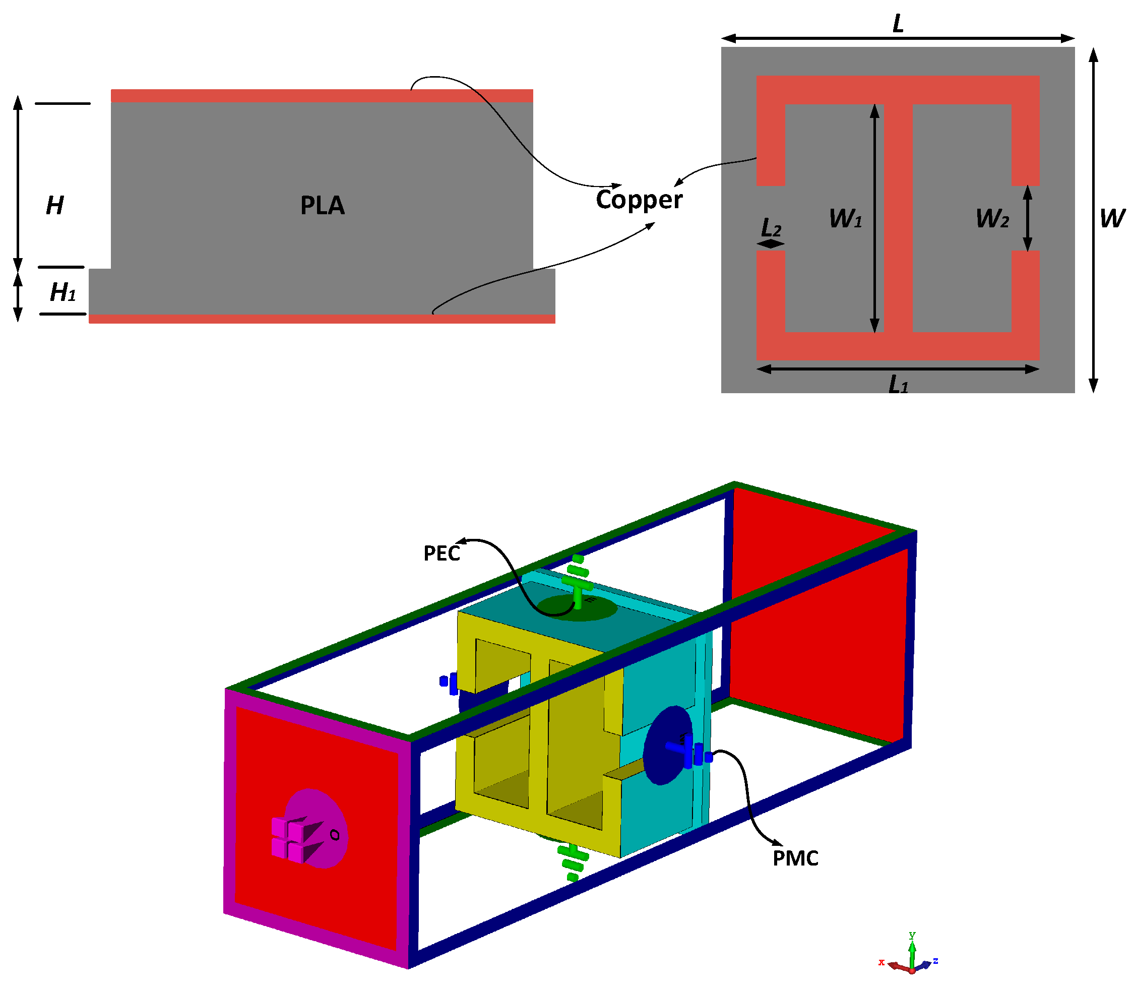
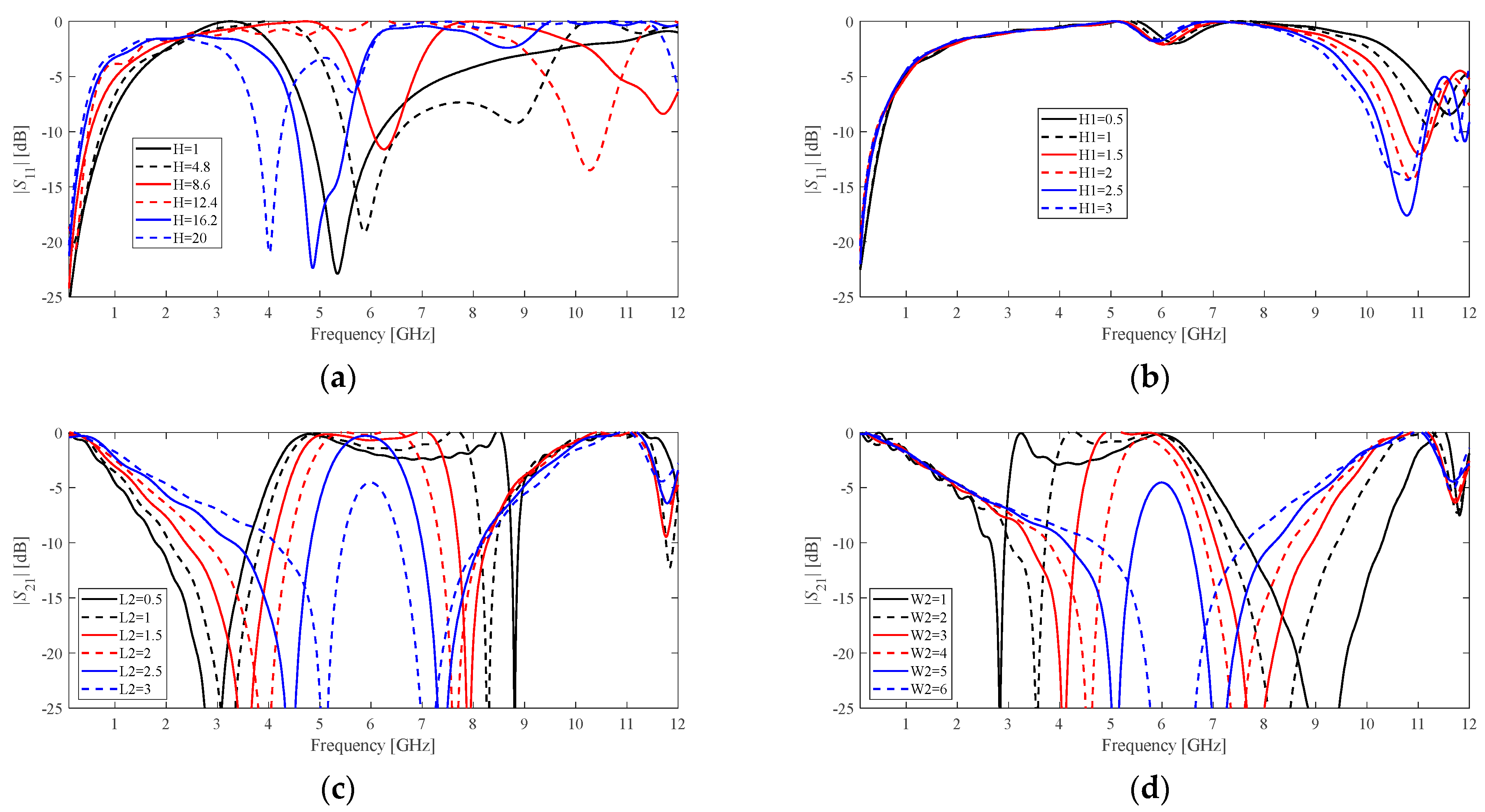
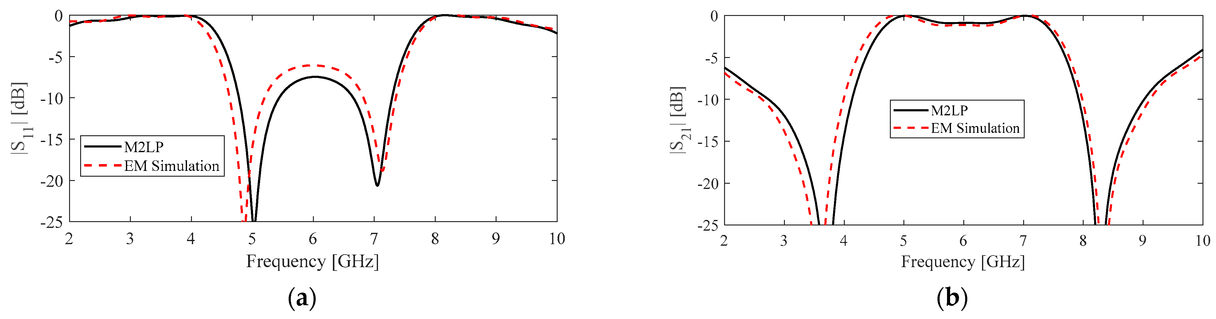
2. Data-Driven Surrogate Model of Frequency Selective Surface Unit Element
3. Surrogate-Assisted Design Optimization of Filtenna
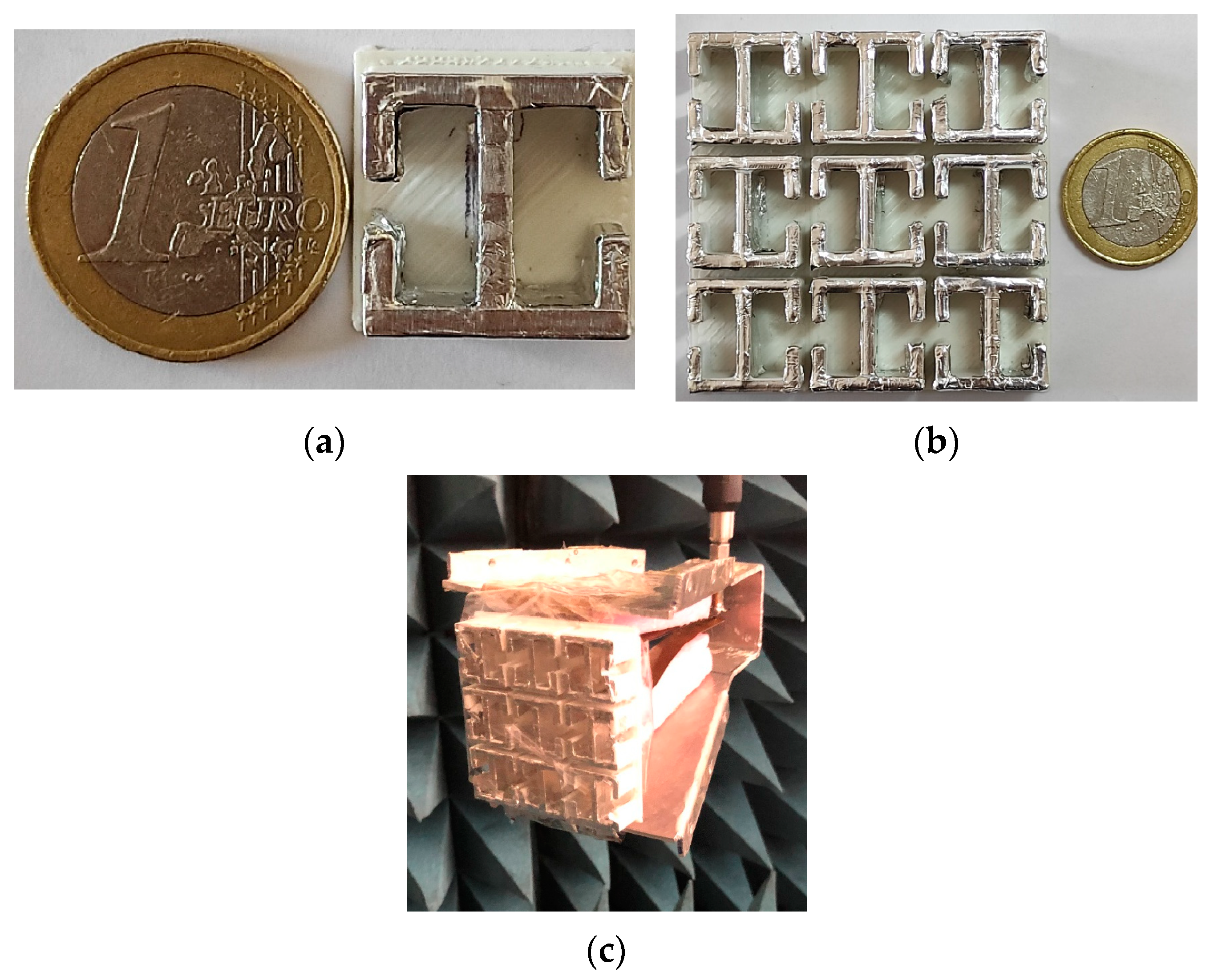
4. Experimental Results
5. Conclusions
Author Contributions
Funding
Data Availability Statement
Acknowledgments
Conflicts of Interest
References
- Engheta, N.; Ziolkowski, R.W. Metamaterials: Physics and Engineering Explorations; John and Wiley and Sons: Hoboken, NJ, USA, 2006. [Google Scholar]
- Sichao, Q.; Sheng, P. Microwave and acoustic absorption metamaterials. Phys. Rev. Appl. 2022, 17, 047001. [Google Scholar]
- Hussain, M.; Awan, W.A.; Alzaidi, M.S.; Hussain, N.; Ali, E.M.; Falcone, F. Metamaterials and Their Application in the Performance Enhancement of Reconfigurable Antennas: A Review. Micromachines 2023, 14, 349. [Google Scholar] [CrossRef] [PubMed]
- Lawrentschuk, N.; Bolton, D.M. Mobile Phone Interference with Medical Equipment and its Clinical Relevance: A Systematic Review. Med. J. Aus. 2004, 181, 145–149. [Google Scholar] [CrossRef] [PubMed]
- Rouco, A.; Cota, N.; Beire, A.R.; Serrador, A. Public Mobile Wideband Networks Interference Impact Assessment on Railways GSM-R Network. In Proceedings of the 2022 International Conference on Electrical, Computer and Energy Technologies (ICECET), Prague, Czech Republic, 20–22 July 2022; pp. 1–6. [Google Scholar]
- Wiklundh, K. Interference challenges for industry communication. In PDF Presentation Slides from Keynote at WFCS; IEEE: Sundsvall, Sweden, 2019. [Google Scholar]
- Iskra, S.; Thomas, B.W.; McKenzie, R.; Rowley, J. Potential GPRS 900/1800 MHz and WCDMA 1900 MHz interference to medical devices. IEEE Trans. Biomed. Eng. 2007, 54, 1858–1866. [Google Scholar] [CrossRef]
- Genç, O.; Bayrak, M.; Yald, E. Analysis of the effects of GSM band-stop the electromagnetic pollution in the RF spectrum. Prog. Electromagn. Res. 2010, 101, 17–32. [Google Scholar] [CrossRef] [Green Version]
- Alves, A.A.C.; da Silva, L.G.; Vilas Boas, E.C.; Spadoti, D.H.; Cerqueira, S.A. Continuously frequency-tunable horn filtennas based on dual-post resonators. Int. J. Anten. Prop. 2019, 2019, 6529343. [Google Scholar] [CrossRef] [Green Version]
- Kumar, A.; Althuwayb, A.A. SIW Resonator-Based Duplex Filtenna. IEEE Ant. Wire. Prop. Let. 2021, 20, 2544–2548. [Google Scholar] [CrossRef]
- Wang, W.; Jin, H.; Yu, W.; Zhang, X.H.; Wu, F.; Chin, K.-S.; Luo, G.Q. A Single-Layer Dual-Circularly Polarized SIW-Cavity-Backed Patch Filtenna With Wide Axial-Ratio Bandwidth. IEEE Ant. Wire. Prop. Let. 2021, 20, 908–912. [Google Scholar] [CrossRef]
- Xiao, J.K.; Liu, X.-Q.; Li, X.-F. Four-port MIMO Filtenna Based on Multi-layer Suspended Coplanar Waveguide. In Proceedings of the 2021 IEEE International Workshop on Electromagnetics: Applications and Student Innovation Competition (iWEM), Guangzhou, China, 7–9 November 2021; pp. 1–3. [Google Scholar]
- Tang, M.-C.; Li, D.; Chen, X.; Wang, Y.; Hu, K.; Ziolkowski, R.W. Compact, Wideband, Planar Filtenna with Reconfigurable Tri-Polarization Diversity. IEEE Trans. Ant. Prop. 2019, 67, 5689–5694. [Google Scholar] [CrossRef]
- Erdemli, Y.E.; Sertel, K.; Gilbert, R.A.; Wright, D.E.; Volakis, J.L. Frequency selective surfaces to enhance performance of broad band reconfigurable arrays. IEEE Trans. Antennas Propag. 2002, 50, 1716–1724. [Google Scholar] [CrossRef]
- Chou, H.-H.; Ke, G.-J. Narrow Bandpass Frequency Selective Surface With High Level of Angular Stability at Ka-Band. IEEE Microw. Wire. Comp. Lett. 2021, 31, 361–364. [Google Scholar] [CrossRef]
- Guo, Q.; Li, Z.; Su, J.; Song, J.; Yang, l.Y. Active Frequency Selective Surface With Wide Reconfigurable Passband. IEEE Access 2019, 7, 38348–38355. [Google Scholar] [CrossRef]
- Lalbakhsh, A.; Afzal, m.U.; Esselle, K.P.; Smith, S.L. All-Metal Wideband Frequency-Selective Surface Bandpass Filter for TE and TM Polarizations. IEEE Trans. Ant. Prop. 2022, 70, 2790–2800. [Google Scholar] [CrossRef]
- De Sabata, A.; Matekovits, L.; Buta, A.; Dassano, G.; Silaghi, A. Frequency Selective Surface for Ultra-Wide Band Filtering and Shielding. Sensors 2022, 22, 1896. [Google Scholar] [CrossRef] [PubMed]
- Yu, N.; Genevet, P.; Kats, M.A.; Aieta, F.; Tetienne, J.P.; Capasso, F.; Gaburro, Z. Light propagation with phase discontinuities: Generalized laws of reflection and refraction. Science 2011, 334, 333–337. [Google Scholar] [CrossRef] [Green Version]
- Shelby, R.A.; Smith, D.R.; Schultz, S. Experimental verification of a negative index of refraction. Science 2001, 292, 77–79. [Google Scholar] [CrossRef] [Green Version]
- Pfeiffer, C.; Grbic, A.A. Metamaterial huygens’ surfaces: Tailoring wave fronts with reflectionless sheets. Phys. Rev. Lett. 2013, 110, 197401. [Google Scholar] [CrossRef] [Green Version]
- Tsilipakos, O.; Koschny, T.; Soukoulis, C.M. Antimatched electromagnetic metasurfaces for broadband arbitrary phase manipulation in reflection. ACS Photonics 2018, 5, 1101–1107. [Google Scholar] [CrossRef] [Green Version]
- Farooq, U.; Shafique, M.F.; Iftikhar, A.; Mughal, M.J. Polarization Insensitive Tri-Band FSS for RF Shielding at Normal and Higher Temperatures by Retrofitting on Ordinary Glass Windows. IEEE Trans. Ant. Prop. 2023, 1. [Google Scholar] [CrossRef]
- Dai, X.W.; Zhang, Y.H.; Yu, W.; Liu, L.; Luo, G.Q. A Broadband Low-Profile Dual-Circularly Polarized Reflect-Array Based on a Single-Layer Microstrip Patch for Ka-Band Application. IEEE Trans. Ant. Prop. 2023, 1. [Google Scholar] [CrossRef]
- Liu, X.; Chen, Z.; Feng, G.; Song, J.; Liu, Y.; Tian, D.; Sun, F.; Liu, Y.; Fei, H.; Yang, Y. Ultra-Wideband Terahertz Absorber Based on Metal–Graphene Hybrid Structure. Mater. Today Commun. 2023, 34, 105185. [Google Scholar] [CrossRef]
- Li, J.; Shi, L.; Chen, H.; Qu, L.; Yi, Y.; Zhang, Q.; Fu, S.; Ma, Y.; Wang, J. High Angular Stability and Polarization Insensitive Optically Transparent Bandpass Frequency Selective Surface Based on Micro Copper Mesh. Optics Comm. 2023, 536, 129365. [Google Scholar] [CrossRef]
- Luo, G.Q.; Hong, W.; Chen, H.; Tang, H.J.; Xin, J.; Yin, X.; Kuai, Z.Q.; Wu, K. Filtenna consisting of horn antenna and substrate integrated waveguide cavity FSS. IEEE Trans. Antennas Propag. 2007, 55, 92–98. [Google Scholar] [CrossRef]
- Mahouti, P.; Güneş, F.; Belen, M.A.; Çalışkan, A.; Demirel, S.; Sharipov, Z. Horn antennas with enhanced functionalities through the use of frequency selective surfaces. Int. J. RF Microw. Comp. Aided Eng. 2016, 26, 287–293. [Google Scholar] [CrossRef]
- Kiani, G.; Olsson, L.; Karlsson, A.; Esselle, K.; Nilsson, M. Cross-dipole band-pass frequency selective surface for energy-saving glass used in buildings. IEEE Trans. Antennas Propag. 2011, 59, 520–525. [Google Scholar] [CrossRef]
- Seager, R.D.; Chauraya, A.; Bowman, J.; Broughton, M.; Philpott, R.; Nimkulrat, N. Fabric based frequency selective surfaces using weaving and screen printing. Electron. Lett. 2013, 49, 1507–1509. [Google Scholar] [CrossRef] [Green Version]
- Imbriale, W.A.; Boccia, L. Space Antenna Handbook; John and Wiley and Sons: Hoboken, NJ, USA, 2012. [Google Scholar]
- Pietrenko-Dabrowska, A.; Koziel, S. Fast EM-driven parameter tuning of microwave circuits with sparse sensitivity updates via principal directions. Knowl. Based Syst. 2022, 252, 109388. [Google Scholar] [CrossRef]
- Koziel, S.; Pietrenko-Dabrowska, A.; Ullah, U. Tolerance-Aware Optimization of Microwave Circuits by Means of Principal Directions and Domain-Restricted Metamodels. IEEE Trans. Microw. Theory Tech. 2022, 70, 4085–4093. [Google Scholar] [CrossRef]
- Çalışkan, A.; Güneş, F. 3D EM Data-driven Artificial Network-based Design Optimization of Circular Reflectarray Antenna with Semi-elliptic Rings for X-band Applications. Microw. Opt. Techn. Lett. 2021, 64, 537–543. [Google Scholar] [CrossRef]
- Uluslu, A. Design of Microstrip Filter by Modeling with Reduced Data. App. Comput. Electrom. Soc. J. 2021, 36, 1453–1459. [Google Scholar] [CrossRef]
- Koziel, S.; Mahouti, P.; Calik, N.; Belen, M.A.; Szczepanski, S. Improved modeling of microwave structures using performance-driven fully-connected regression surrogate. IEEE Access 2021, 9, 71470–71481. [Google Scholar] [CrossRef]
- PLA 1.75 mm 3D Printing Filament. Available online: https://cel-uk.com/shop/pla/ (accessed on 24 November 2022).
- Calik, N.; Belen, M.A.; Mahouti, P. Deep learning base modified MLP model for precise scattering parameter prediction of capacitive feed antenna. Int. J. Numer. Model. 2020, 33, e2682. [Google Scholar] [CrossRef]
- Simruni, M.; Jam, S. Design of High Gain, Wideband Microstrip Resonant Cavity Antenna Using FSS Superstrate with Equivalent Circuit Model. AEU Int. J. Electr. Comm. 2019, 112, 152935. [Google Scholar] [CrossRef]
- El-Ghazaly, S.M. Heterojunction Field Effect Transistors. In Encyclopedia of Materials: Science and Technology; Elsevier: Amsterdam, The Netherlands, 2001; pp. 3760–3767. ISBN 9780080431529. [Google Scholar]
- Güneş, F.; Demirel, S.; Mahouti, P. Design of a front–end amplifier for the maximum power delivery and required noise by HBMO with support vector microstrip model. Radioengineering 2014, 23, 134–143. [Google Scholar]
- Keskin, A.K.; Senturk, M.D.; Çalişkan, A.; Türk, A.S. UWB Compact TEM Ridged Horn Antenna. In Proceedings of the Annual Review of Progress in Applied Computational Electromagnetics, Jacksonville, FL, USA, 23–27 March 2014; pp. 114–118. [Google Scholar]
- Genc, A.; Basyigit, I.B.; Colak, B.; Helhel, S. Investigation of the Characteristics of Low-Cost and Lightweight Horn Array Antennas with Novel Monolithic Waveguide Feeding Networks. AEU Int. J. Electr. Comm. 2018, 89, 15–23. [Google Scholar] [CrossRef]
- Decrossas, E.; Reck, T.; Lee, C.; Jung-Kubiak, C.; Mehdi, I.; Chattopadhyay, G. Evaluation of 3D Printing Technology for Corrugated Horn Antenna Manufacturing. In Proceedings of the 2016 IEEE International Symposium on Electromagnetic Compatibility (EMC), Ottawa, ON, Canada, 25–29 July 2016. [Google Scholar]
- Kyovtorov, V.; Georgiev, I.; Margenov, S.; Stoychev, D.; Oliveri, F.; Tarchi, D. New Antenna Design Approach—3D Polymer Printing and Metallization. Experimental Test at 14–18 GHz. AEU Int. J. Electro. Comm. 2017, 73, 119–128. [Google Scholar] [CrossRef]
- Ghorbani, F.; Beyraghi, S.; Shabanpour, J.; Oraizi, H.; Soleimani, H.; Soleimani, M. Deep neural network-based automatic metasurface design with a wide frequency range. Sci. Rep. 2021, 11, 7102. [Google Scholar] [CrossRef]
- Bauerle, R.J.; Schrimpf, R.; Gyorko, E.; Henderson, J. The use of a dielectric lens to improve the efficiency of a dual-polarized quad-ridge horn from 5 to 15 GHz. IEEE Trans. Antennas Propag. 2009, 57, 1822–1825. [Google Scholar] [CrossRef]
- Türk, A.S.; Keskin, A.K.; Şentürk, M.D. Dielectric loaded TEM horn-fed ridged horn antenna design for ultrawideband ground-penetrating impulse radar. Turkish J. Elec. Eng. Comp. Sci. 2015, 23, 1479–1488. [Google Scholar] [CrossRef]
- Belen, M.A.; Mahouti, P. Realization of dielectric sheets for gain improvement of ultra-wideband horn antennas using 3D printer technology. Appl. Comput. Electromag. Soc. J. 2019, 34, 760–764. [Google Scholar]
- Türk, A.S.; Keskin, A.K. Partially dielectricloaded ridged horn antenna design for ultrawideband gain and radiation performance enhancement. IEEE Antennas Wirel. Propag. Lett. 2012, 11, 921–924. [Google Scholar] [CrossRef]
- Cicchetti, R.; Cicchetti, V.; Faraone, A.; Foged, L.; Testa, O. A Wideband High-Gain Dielectric Horn-Lens Antenna for Wireless Communications and UWB Applications. IEEE Trans. Ant. Prop. 2023, 71, 1304–1318. [Google Scholar] [CrossRef]
- Yu, W.; Peng, L.; Liu, Y.; Zhao, Q.; Jiang, X.; Li, S. An Ultrawideband and High-Aperture-Efficiency All-Dielectric Lens Antenna. IEEE Antennas Wirel. Prop. Lett. 2021, 20, 2442–2446. [Google Scholar] [CrossRef]
- Goode, I.; Saavedra, C.E. 3D Printed Linearly Polarized X-Band Conical Horn Antenna and Lens. IEEE Open J. Ant. Prop. 2022, 3, 549–556. [Google Scholar] [CrossRef]
- Zhang, Z.-Y.; Lu, K.; Leung, K.W. Gain Enhancement of Horn Antenna Using a Metal Lens. IEEE Trans. Ant. Prop. 2023, 71, 1337–1349. [Google Scholar] [CrossRef]
- Marzall, L.; Danielson, P.; Lasser, G.; Popovic, Z. Broadband Small-Aperture High-Gain Ridge Horn Antenna Array Element. IEEE Antennas Wirel. Prop. Lett. 2021, 20, 708–712. [Google Scholar] [CrossRef]


| Parameter | Lower Boundary | Upper Boundary |
|---|---|---|
| H | 1 | 20 |
| H1 | 0.5 | 3 |
| L2 | 0.5 | 5 |
| W2 | 1 | 10 |
| Model | Hyper-Parameters | K-Fold/Holdout | Total Training Time [Minutes] |
|---|---|---|---|
| MLP | Hidden Layer size-2; Hidden Layer Neurons sizes 15–20; Activation function sigmoid | 6.0%/7.5% | ~17.5 |
| SVRM | Kernel-function: Radial, Type: Epsilon, Epsilon: 0.1. | 6.4%/8.1% | ~14.0 |
| Gradient Boosted Tree | Learning-rate = 0.045; Depth: 5; N. estimators: 4800 | 7.6%/8.4% | ~8.5 |
| Keras Deep Residual NN Regressor | N. Layers:2; N. Neurons: 512–512 | 4.6%/5.4% | ~27.0 |
| Gaussian Process Regression | Kernel-function: ard-matern3/2; Prediction-method: Block-coordinate-descent; block-size: 750 | 5.4%/6.2% | ~27.0 |
| M2LP | Depth: 3, initial Neuron N.: 64 | 3.9%/4.7% | ~21.0 |
| Convolutional Neural Networks | N. Layers:3; N. Neurons: 64–128-256 | 4.3%/5.2% | ~29.0 |
| FCRM [36] | Block size = 3; Sublock = Fully Connect + Leak ReLU Sublock neurons Number = {256, 1024, 1024}) | 3.2%/4.1% | ~42.5 |
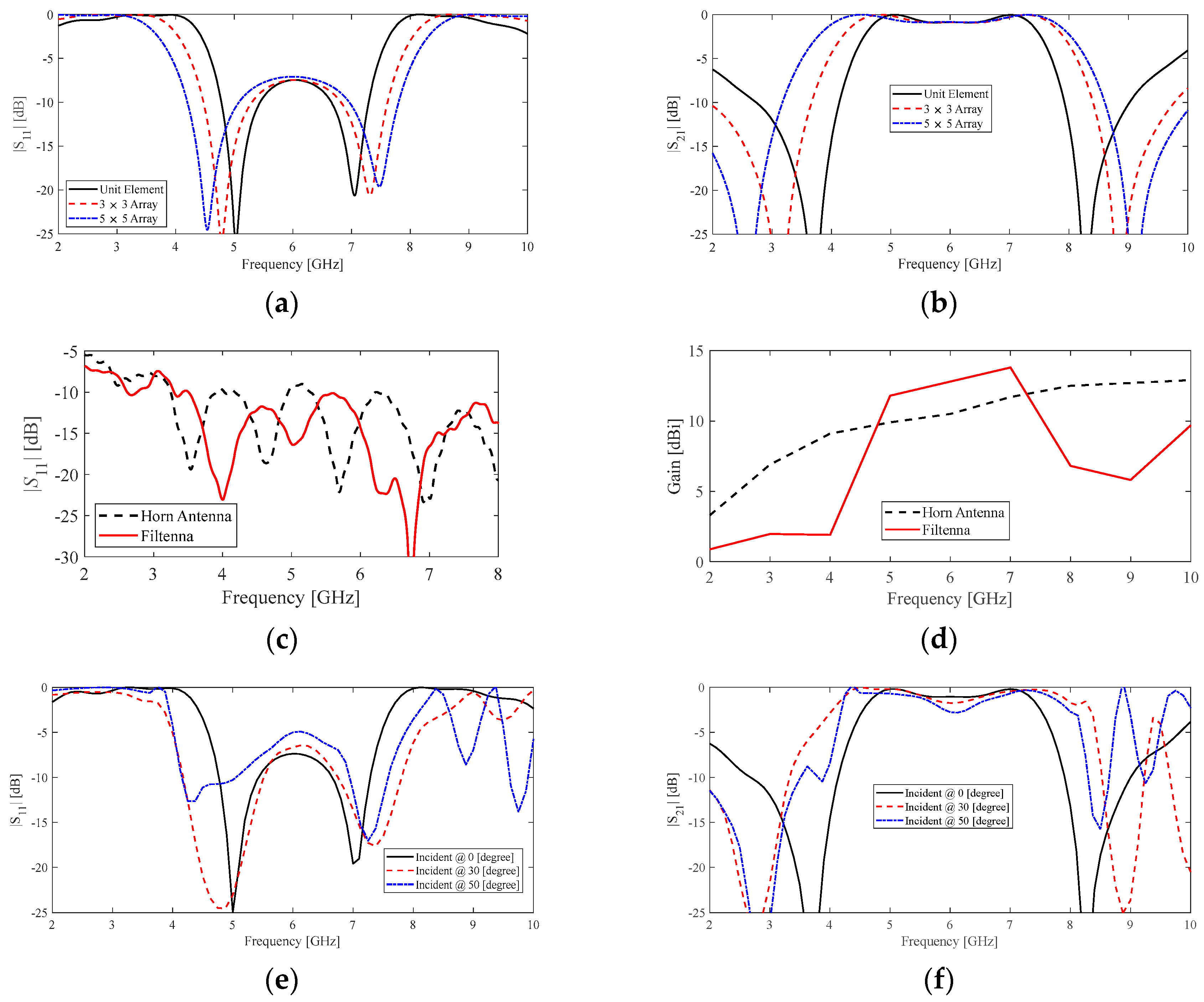
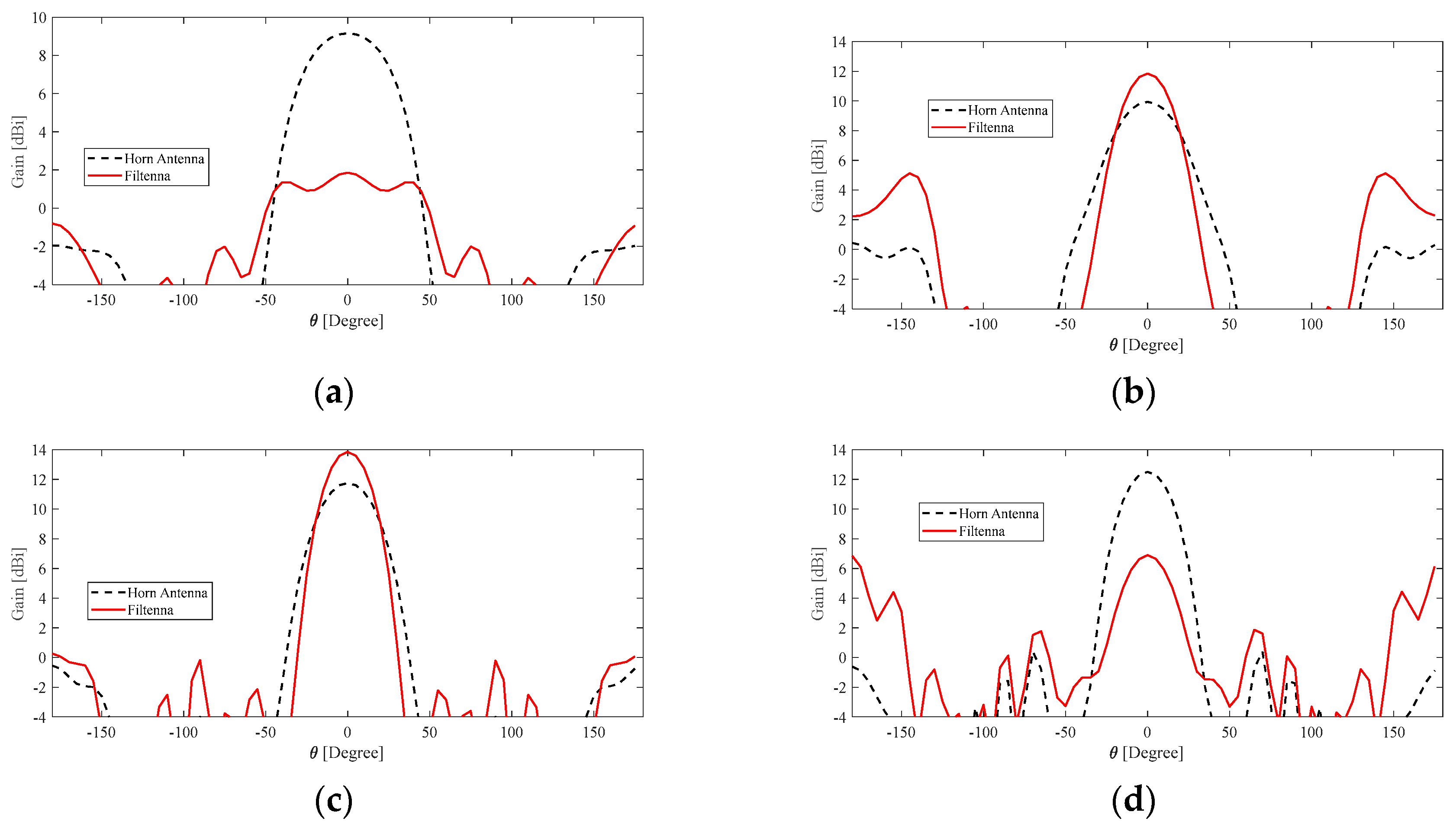
| Frequency [GHz] | TEM | FILTENNA |
|---|---|---|
| 4 | 9.1 | 1.9 |
| 5 | 9.9 | 11.8 |
| 6 | 10.5 | 12.8 |
| 7 | 11.7 | 13.8 |
| 8 | 12.5 | 6.8 |
| Work | Operating Band [GHz] | Design Size [mm] | Gain Alteration [dBi]/[GHz] | ||||
|---|---|---|---|---|---|---|---|
| 4 | 5 | 6 | 7 | 8 | |||
| This work | 4–8 | 60 × 60 | –7.2 | 1.9 | 2.3 | 2.1 | –5.7 |
| [47] | 5–15 | 16 × 16 | 0 | 1 | 0.5 | 0 | 0.5 |
| [48] | 1–15 | 60 × 100 | 2 | 2.5 | 3 | 3 | 4 |
| [49] | 2–13 | 25 × 73.5 | 1 | 1.5 | 2 | 2.5 | 2.7 |
| [50] | 2–13 | 100 × 100 | 0 | 5 | 4.5 | 5 | 2 |
| [51] | 3–12 | 80 × 800 | 2 | 1 | 3 | 2 | 3 |
| [52] | 6–18 | 90 × 90 | --- | --- | 4 | 5 | 5.5 |
| [53] | 8–12 | 114 × 114 | --- | --- | --- | --- | 1.5 |
| [54] | 8–18 | 106 × 16 | --- | --- | --- | --- | 2 |
| [55] | 6–12 | 22 × 20 | --- | --- | 1 | 0 | 1.5 |
Disclaimer/Publisher’s Note: The statements, opinions and data contained in all publications are solely those of the individual author(s) and contributor(s) and not of MDPI and/or the editor(s). MDPI and/or the editor(s) disclaim responsibility for any injury to people or property resulting from any ideas, methods, instructions or products referred to in the content. |
© 2023 by the authors. Licensee MDPI, Basel, Switzerland. This article is an open access article distributed under the terms and conditions of the Creative Commons Attribution (CC BY) license (https://creativecommons.org/licenses/by/4.0/).
Share and Cite
Mahouti, P.; Belen, A.; Tari, O.; Belen, M.A.; Karahan, S.; Koziel, S. Data-Driven Surrogate-Assisted Optimization of Metamaterial-Based Filtenna Using Deep Learning. Electronics 2023, 12, 1584. https://doi.org/10.3390/electronics12071584
Mahouti P, Belen A, Tari O, Belen MA, Karahan S, Koziel S. Data-Driven Surrogate-Assisted Optimization of Metamaterial-Based Filtenna Using Deep Learning. Electronics. 2023; 12(7):1584. https://doi.org/10.3390/electronics12071584
Chicago/Turabian StyleMahouti, Peyman, Aysu Belen, Ozlem Tari, Mehmet Ali Belen, Serdal Karahan, and Slawomir Koziel. 2023. "Data-Driven Surrogate-Assisted Optimization of Metamaterial-Based Filtenna Using Deep Learning" Electronics 12, no. 7: 1584. https://doi.org/10.3390/electronics12071584