
Numerical Calculation for the Line-of-Sight Attitudes of Multi-Address Transceivers without 2:1 Transmissions for Space Laser Communication Networking

Abstract
:1. Introduction
- (1)
- A new method of establishing a reflector coordinate system is proposed, which realizes the conversion of projections between a reflector and LOS in different coordinate systems.
- (2)
- A mathematical method for the mutual conversion between the attitudes of a multi-reflector is proposed, which can realize the numerical solution of the attitudes of a reflector and the LOS at any position. The attitude of all the reflectors and the LOS can be calculated simultaneously by a single gyro.
- (3)
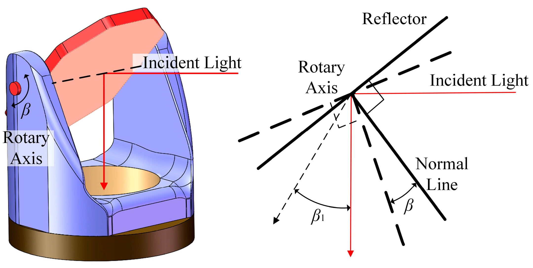
- According to the spatial transformation relation of Snell’s law of reflection, the Snell transformation matrix is established. Through the Snell transformation of LOS in different reflector coordinate systems, the doubled coupling effects produced in the numerical solution of the LOS attitude of a multi-reflector are eliminated.
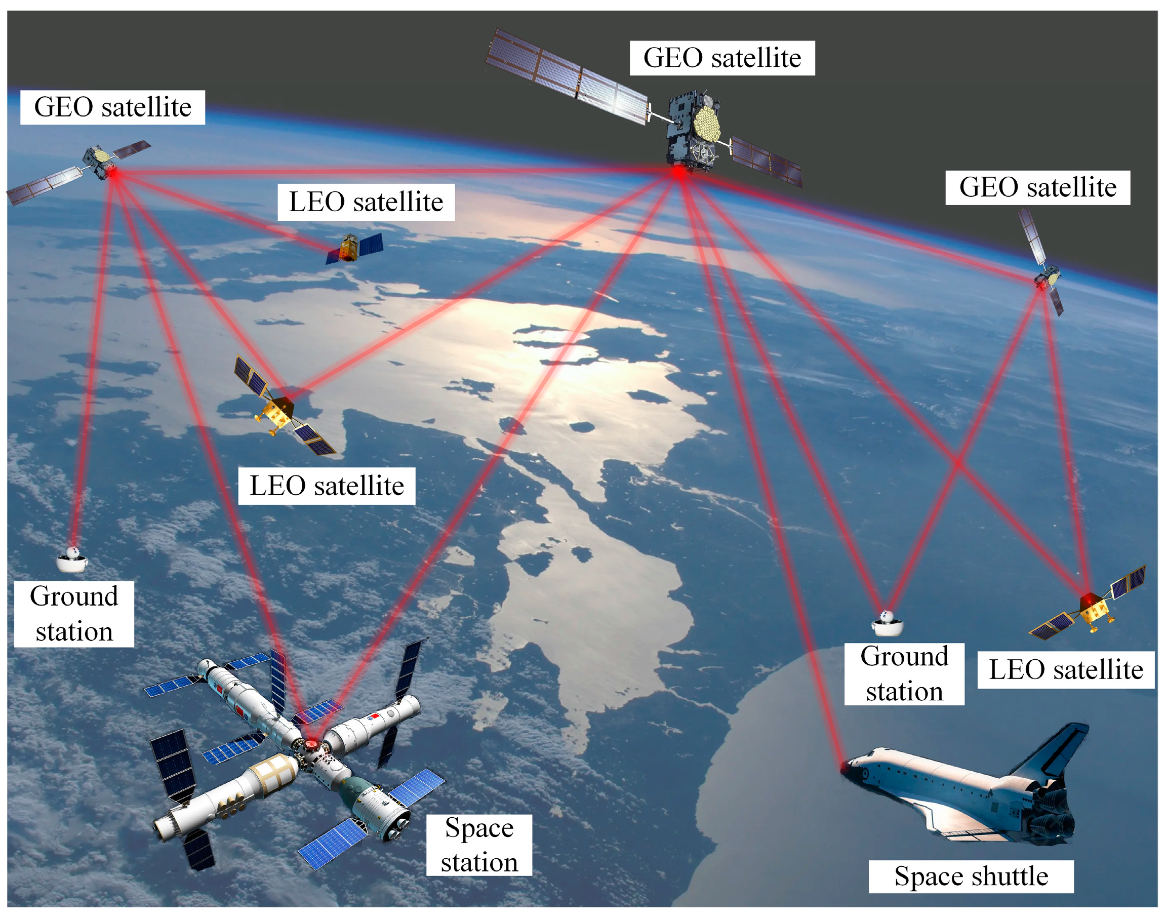
2. Scheme for Space Laser Communication Networking
2.1. Networking Principle
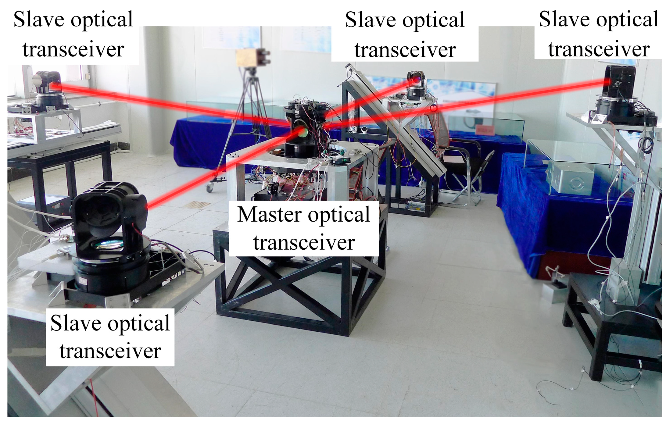
2.2. Indoor Experiment for Laser Communication Networking
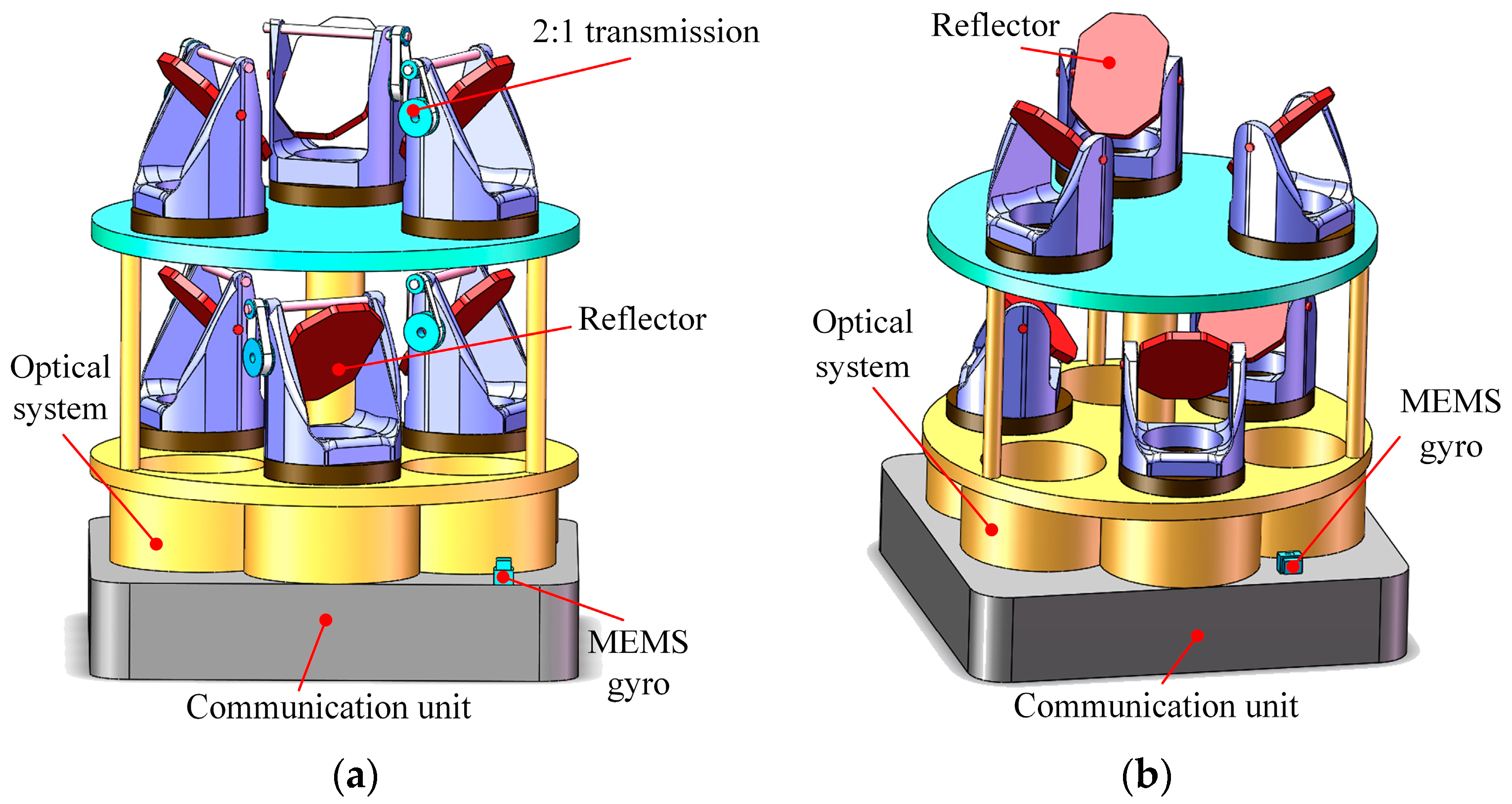
2.3. Multi-Reflector Scheme for Laser Communication Networking
3. Calculations for the Attitudes of the LOS of the Multi-Reflectors
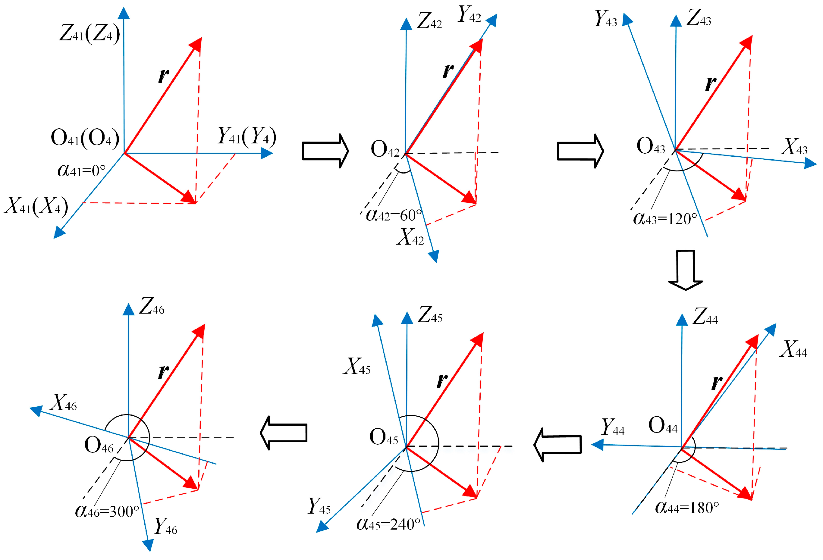
3.1. Establishing the Coordinate System
3.2. Mathematical Model of the Attitudes of the LOS of the Multi-Reflector
3.3. Numerical Calculations for the Attitudes of the LOS of the Multi-Reflector
3.3.1. Quaternion-Based Numerical Calculation Model
3.3.2. Direct Calculation Method
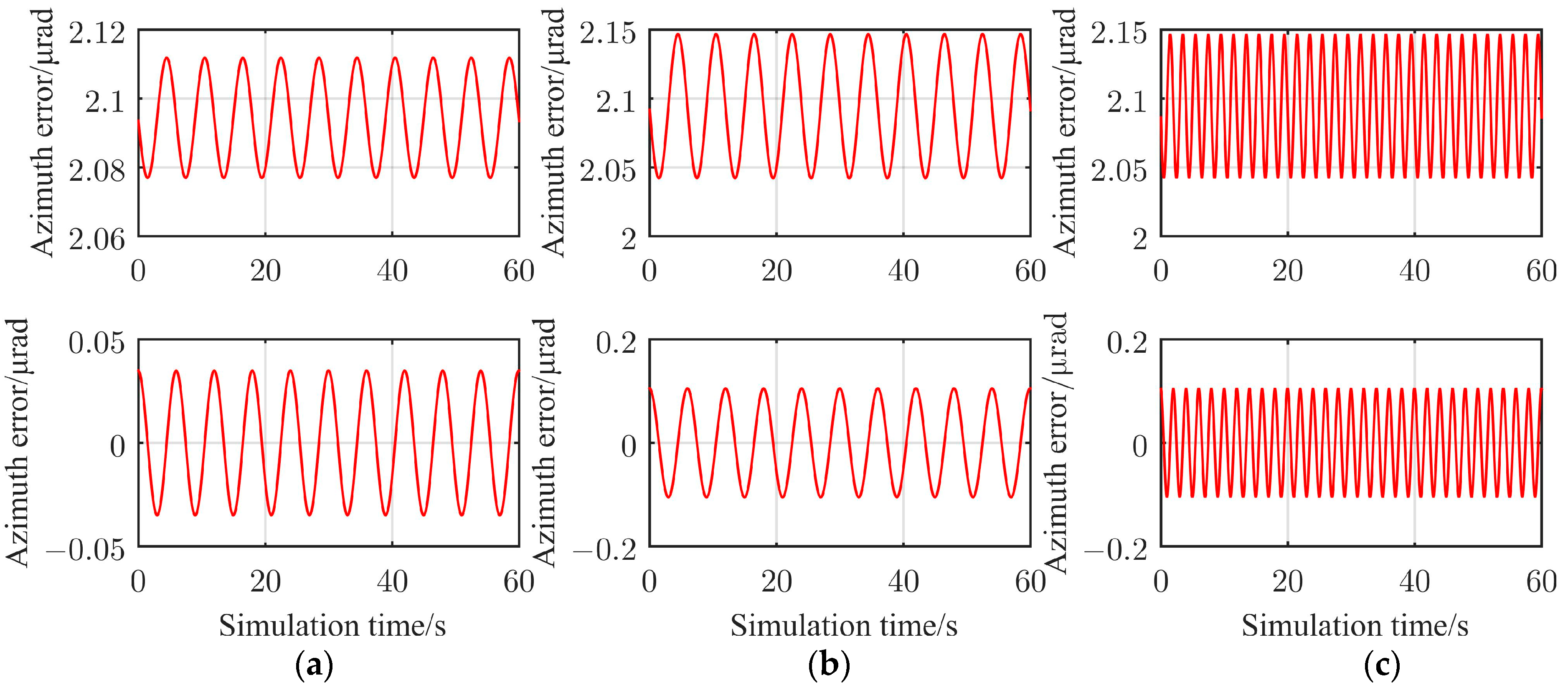
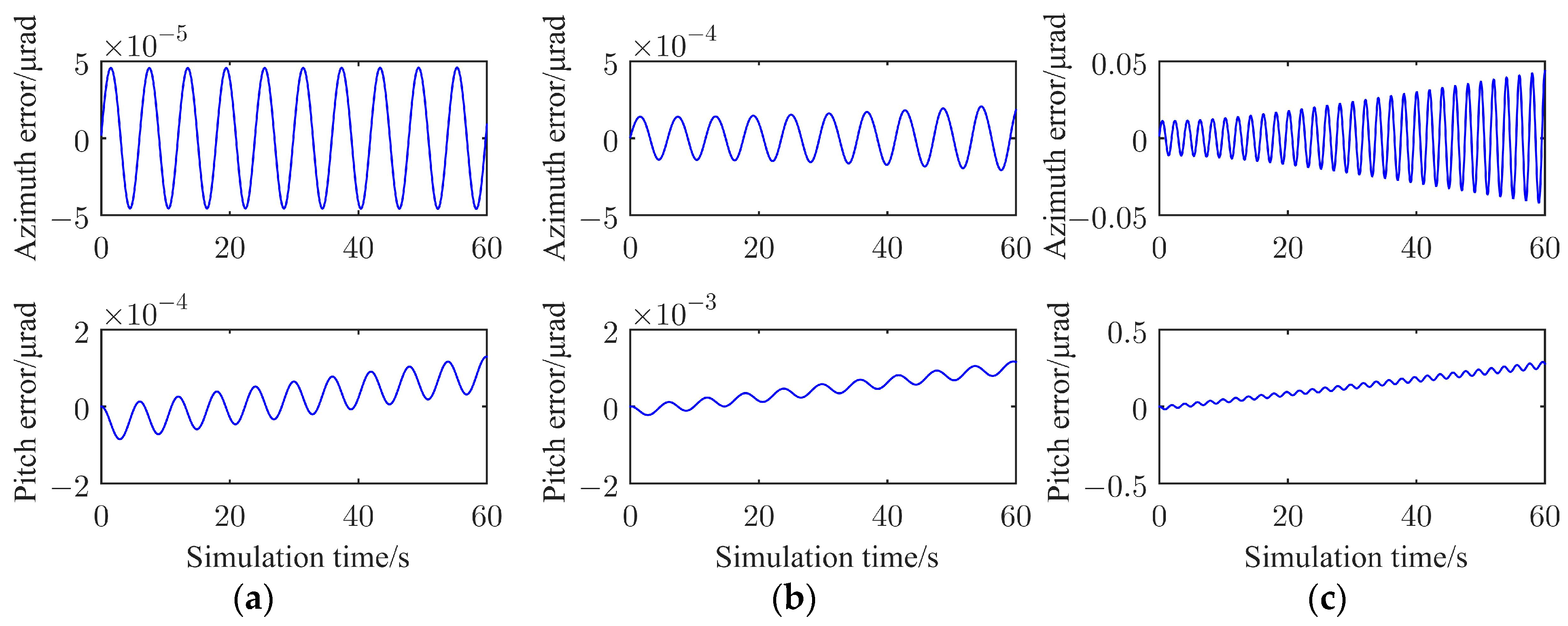
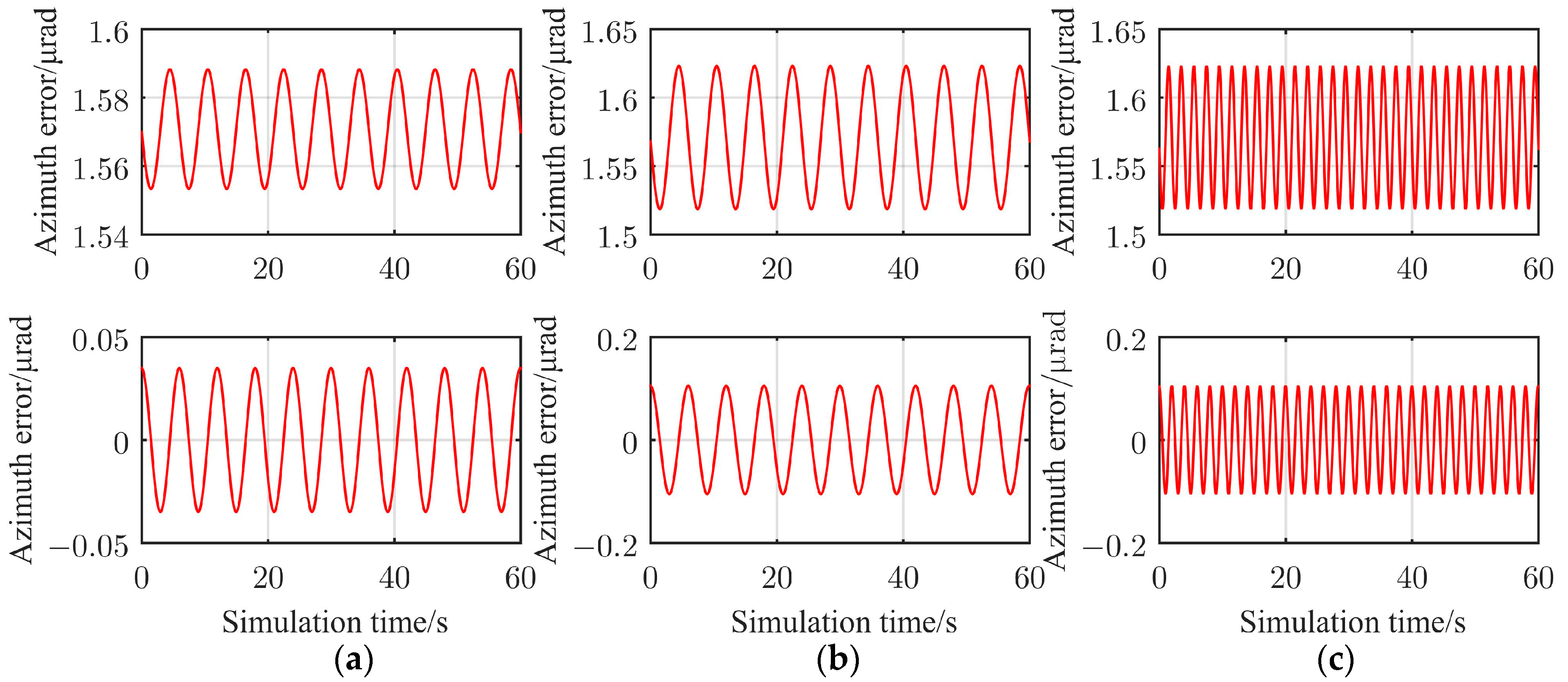
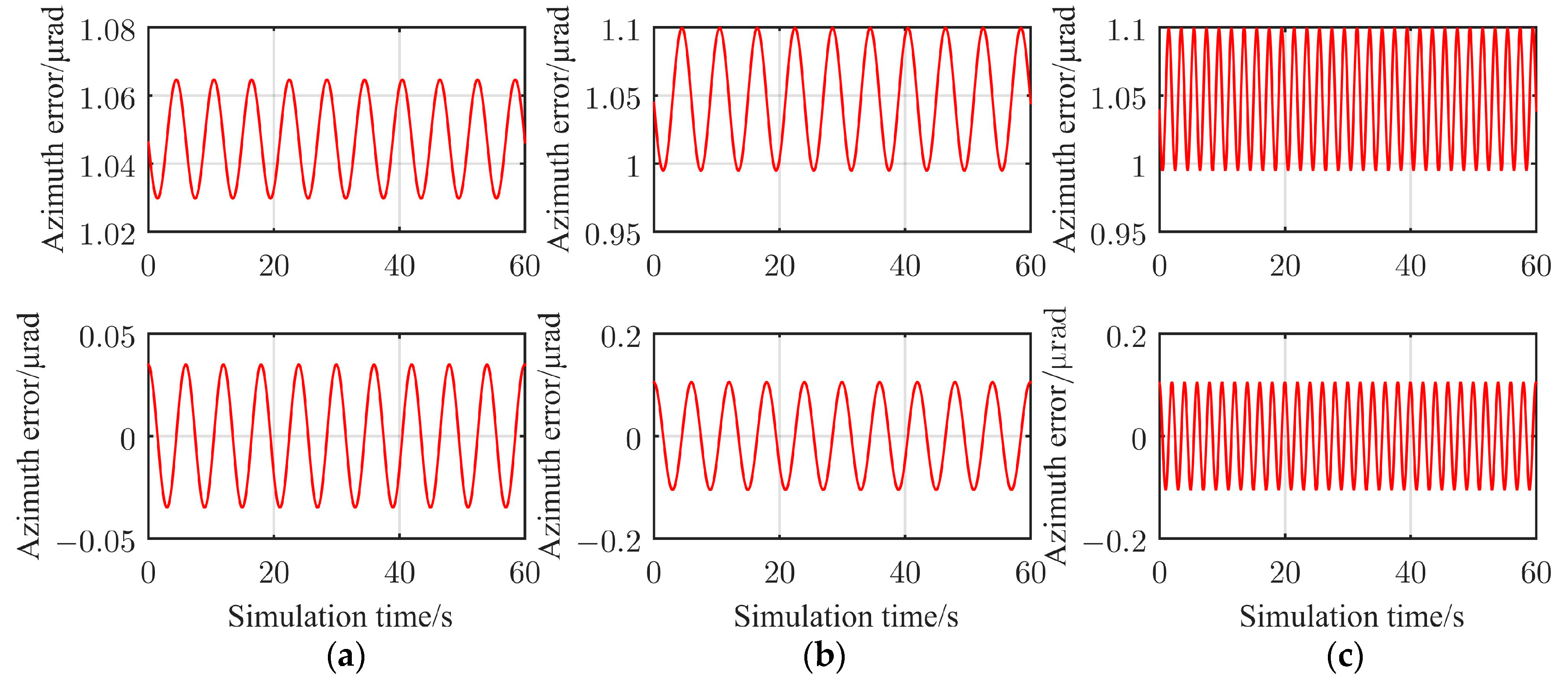
4. Simulation Experiment
5. Conclusions
Author Contributions
Funding
Data Availability Statement
Conflicts of Interest
References
- Wang, C.; Zhang, T.; Tong, S.; Li, Y.; Jiang, L.; Liu, Z.; Shi, H.; Liu, J.; Jiang, H. Pointing and tracking errors due to low-frequency deformation in inter-satellite laser communication. J. Mod. Opt. 2019, 66, 430–437. [Google Scholar] [CrossRef]
- Chaudhry, A.U.; Yanikomeroglu, H. Laser intersatellite links in a starlink constellation: A classification and analysis. IEEE Vehic. Technol. Mag. 2021, 16, 48–56. [Google Scholar] [CrossRef]
- Li, R.; Lin, B.; Liu, Y.; Dong, M.; Zhao, S. A survey on laser space network: Terminals, links, and architectures. IEEE Access 2022, 10, 34815–34834. [Google Scholar] [CrossRef]
- Chen, S.; Liang, Y.; Sun, S.; Kang, S.; Cheng, W.; Peng, M. Vision, requirements, and technology trend of 6G: How to tackle the challenges of system coverage, capacity, user data-rate and movement speed. IEEE Wirel. Commun. 2020, 27, 218–228. [Google Scholar] [CrossRef] [Green Version]
- Edwards, B.; Randazzo, T.; Babu, N.; Murphy, K.; Albright, S.; Cummings, N.; Ocasio-Perez, J.; Potter, W.; Roder, R.; Zehner, S.A. Challenges, Lessons Learned, and Methodologies from the LCRD Optical Communication System AI&T. In Proceedings of the 2022 IEEE International Conference on Space Optical Systems and Applications (ICSOS), Kyoto City, Japan, 28–31 March 2022; pp. 22–31. [Google Scholar]
- Chishiki, Y.; Yamakawa, S.; Takano, Y.; Miyamoto, Y.; Araki, T.; Kohata, H. Overview of optical data relay system in JAXA. In Proceedings of the Free-Space Laser Communication and Atmospheric Propagation XXVIII, San Francisco, CA, USA, 13–18 February 2016; pp. 114–118. [Google Scholar]
- Yamakawa, S.; Chishiki, Y.; Sasaki, Y.; Miyamoto, Y.; Kohata, H. JAXA’s optical data relay satellite programme. In Proceedings of the 2015 IEEE International Conference on Space Optical Systems and Applications (ICSOS), New Orleans, LA, USA, 26–28 October 2015; pp. 1–3. [Google Scholar]
- Zhang, Y.L.; An, Y.; Wang, C.H.; Jiang, L.; Zhan, J.T.; Liu, X.Z.; Jiang, H.L. Research on rotating paraboloid based surface in space laser communication network. Acta Opt. Sin. 2015, 35, 86–90. [Google Scholar] [CrossRef]
- Zhang, T.; Mao, S.; Fu, Q.; Cao, G.; Su, S.; Jiang, H. Networking optical antenna of space laser communication. J. Laser Appl. 2017, 29, 012013. [Google Scholar] [CrossRef]
- Wang, L.; Zhang, L.; Meng, L.; Bai, Y. A calculation method for line-of-sight stable attitude of networked optical transceiver based on depth feedforward neural network. In Proceedings of the 2022 3rd International Conference on Computer Vision, Image and Deep Learning & International Conference on Computer Engineering and Applications (CVIDL & ICCEA), Changchun, China, 20–22 May 2022; pp. 32–35. [Google Scholar]
- Kennedy, P.J.; Kennedy, R.L. Direct versus indirect line of sight (LOS) stabilization. IEEE Trans. Control Syst. Technol. 2003, 11, 3–15. [Google Scholar] [CrossRef]
- Hamilton, A. Strapdown optical stabilization system for EO sensors on moving platforms. Design and Engineering of Optical Systems. SPIE 1996, 2774, 631–645. [Google Scholar]
- Mao, Y.; Tian, J.; Ma, J.G. Realization of LOS (Line of Sight) stabilization based on reflector using carrier attitude compensation method. In XX International Symposium on High-Power Laser Systems and Applications 2014. SPIE 2015, 9255, 1003–1008. [Google Scholar]
- Walter, R.E.; Danny, H.; Donaldson, J. Stabilized inertial measurement system (SIMS). Laser Weapons Technology III. SPIE 2002, 4724, 57–68. [Google Scholar]
- Schneeberger, T.J.; Barker, K.W. High-altitude balloon experiment: A testbed for acquisition, tracking, and pointing technologies. Acquisition, Tracking, and Pointing VII. SPIE 1993, 1950, 2–15. [Google Scholar]
- Gilmore, J.P.; Luniewicz, M.F.; Sargent, D. Enhanced precision pointing jitter suppression system. Laser and Beam Control Technologies. SPIE 2002, 4632, 38–49. [Google Scholar]
- Hilkert, J.M. Inertially stabilized platform technology concepts and principles. IEEE Contr. Syst. Mag. 2008, 28, 26–46. [Google Scholar] [CrossRef]
- Hilkert, J.M. A comparison of inertial line-of-sight stabilization techniques using mirrors. In Proceedings of the Acquisition, Tracking, and Pointing XVIII, Orlando, FL, USA, 12–16 April 2004; pp. 13–22. [Google Scholar]
- Masten, M.K. Inertially stabilized platforms for optical imaging systems. IEEE Control. Syst. Mag. 2008, 28, 47–64. [Google Scholar]
- Wu, Y.; Litmanovich, Y.A. Strapdown attitude computation: Functional iterative integration versus taylor series expansion. Gyroscopy Navig. 2020, 11, 263–276. [Google Scholar] [CrossRef]
- Zhao, C.; Fan, J.; Liu, N. Simulation Research on Attitude Solution Method of Micro-Mini Missile. J. Syst. Simul. 2019, 31, 2877–2884. [Google Scholar] [CrossRef]
- Wu, S.; Radice, G.; Gao, Y.; Sun, Z. Quaternion-based finite time control for spacecraft attitude tracking. Acta Astronaut. 2011, 69, 48–58. [Google Scholar] [CrossRef]
- Savage, P.G. Strapdown inertial navigation integration algorithm design part 1: Attitude algorithms. J. Guid. Contr. Dynam. 1998, 21, 19–28. [Google Scholar] [CrossRef]
- Shi, K.; Liu, M. Strapdown inertial navigation quaternion fourth-order runge-kutta attitude algorithm. J. Detect. Contr. 2019, 41, 61–65. [Google Scholar]
- Zhang, Z.; Geng, L.; Fan, Y. Performance Analysis of Three Attitude Algorithms for SINS. Acad. J. Comput. Inform. Sci. 2022, 5, 1–5. [Google Scholar] [CrossRef]
- Lee, J.G.; Yoon, Y.J.; Mark, J.G.; Tazartes, D.A. Extension of strapdown attitude algorithm for high-frequency base motion. J. Guid. Contr. Dynam. 1990, 13, 738–743. [Google Scholar] [CrossRef]
- Jiang, Y.F.; Lin, Y.P. Improved strapdown coning algorithms. IEEE Trans. Aerosp. Electr. Syst. 1992, 28, 484–490. [Google Scholar] [CrossRef]


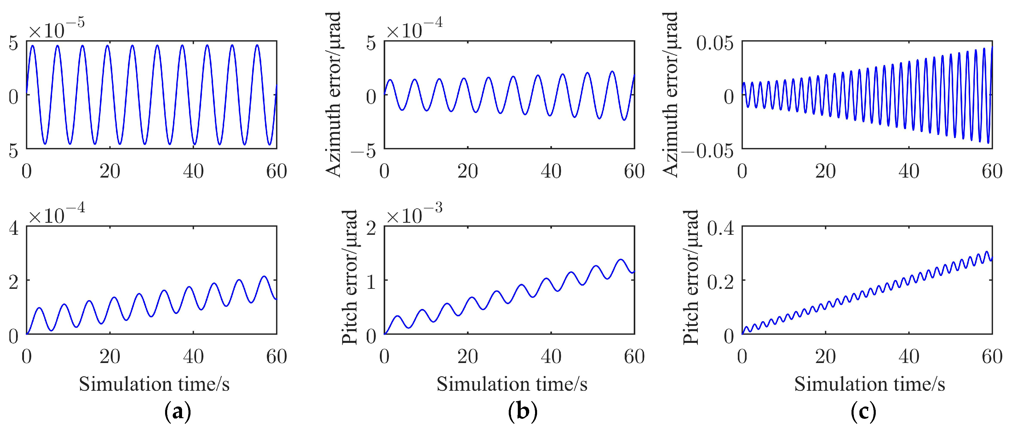
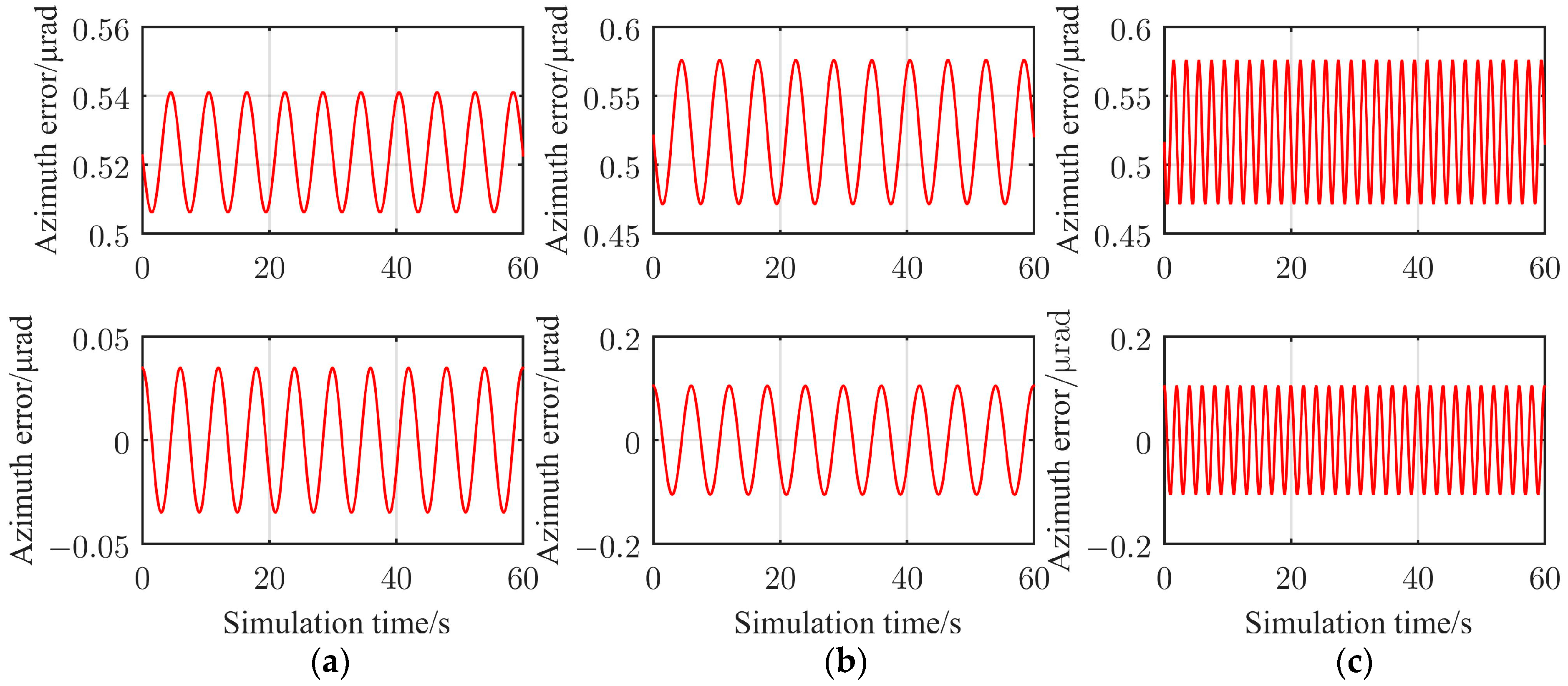
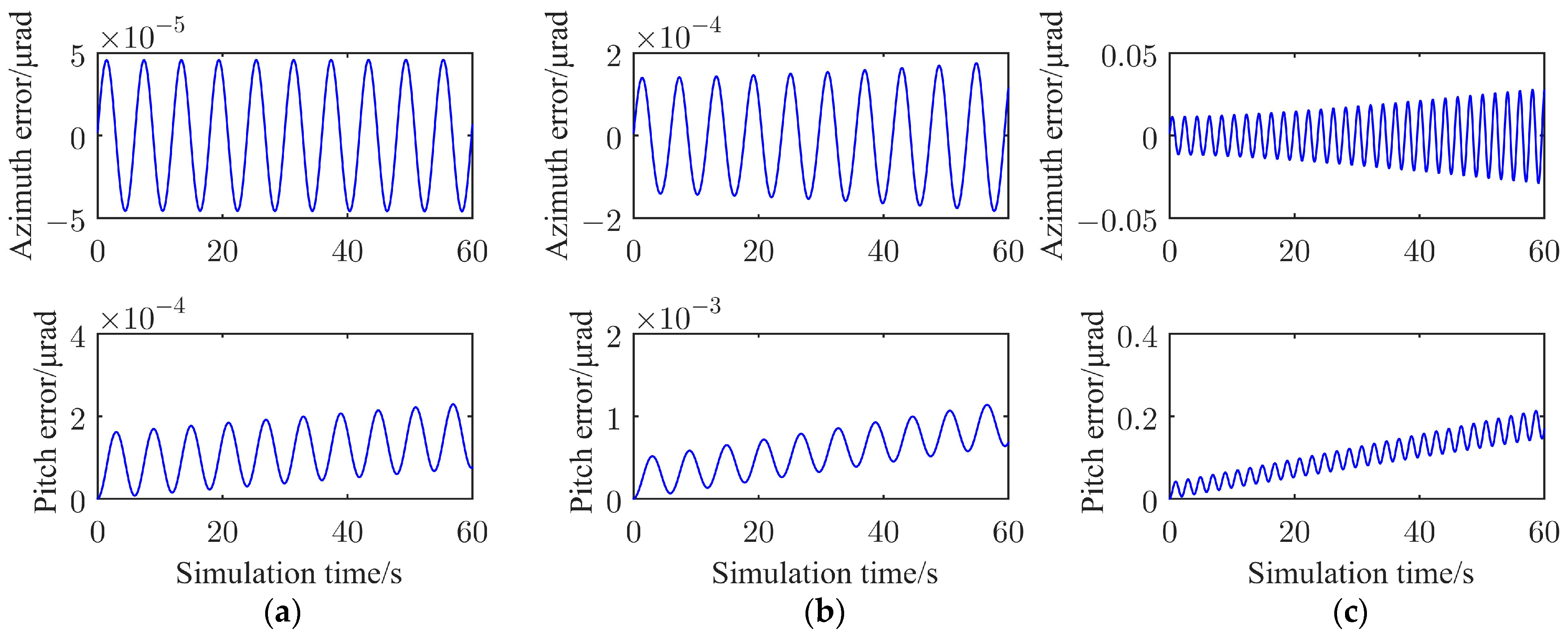
| Coordinate Systems of the Reflectors | Attitudes | (a) a = 1°, ω = 60°/s | (b) a = 1°, ω = 180°/s | (c) a = 3°, ω = 180°/s |
|---|---|---|---|---|
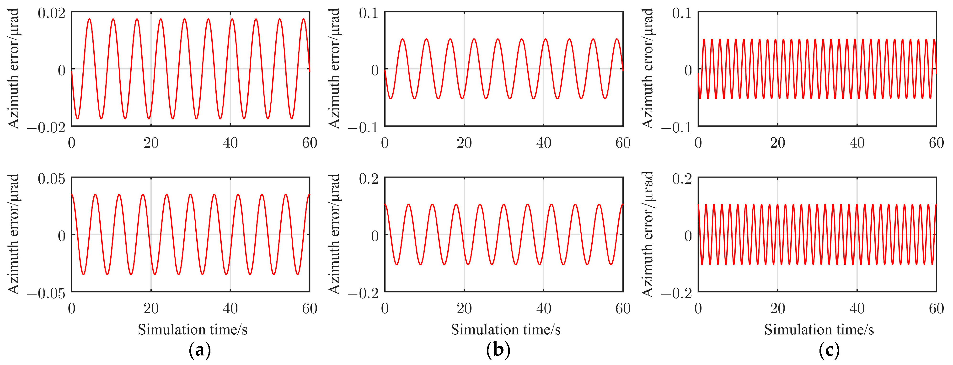
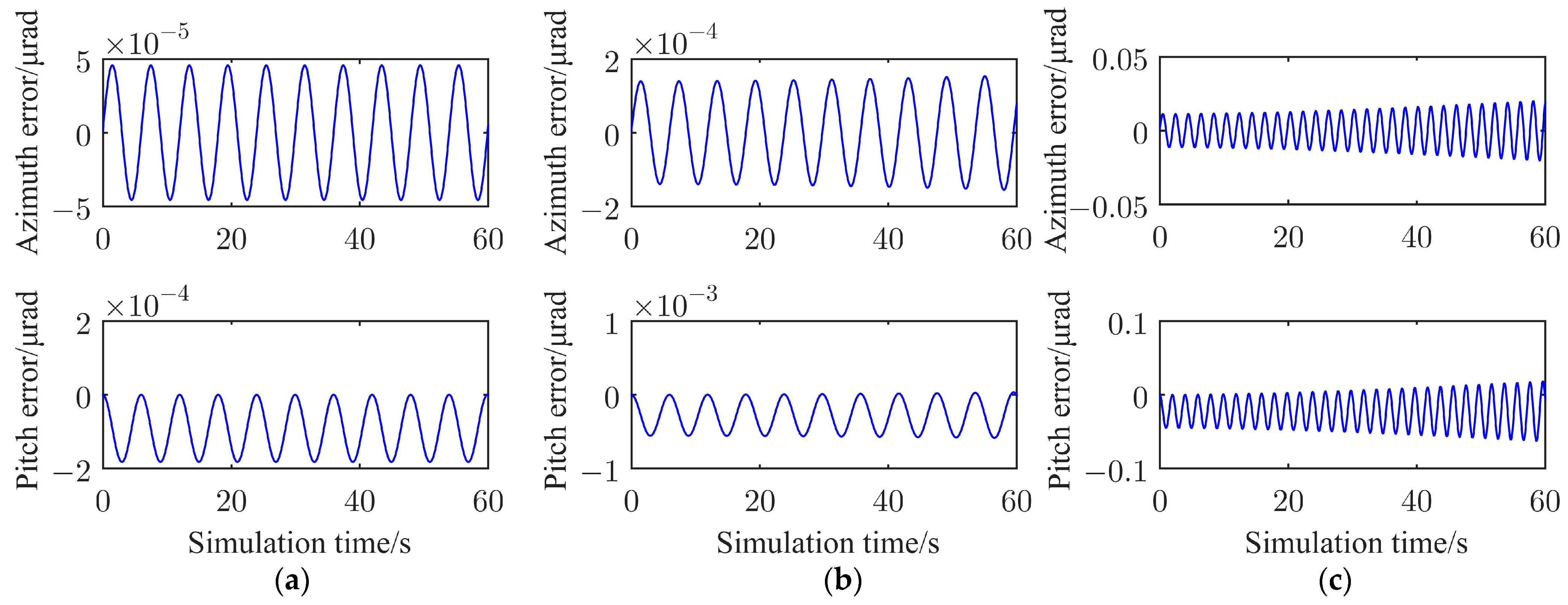
| O41X41Y41Z41 | Azimuth | 4.6 × 10⁻⁵ | 1.6 × 10⁻⁴ | 2.0 × 10⁻² |
| Pitch | 1.8 × 10⁻⁴ | 5.9 × 10⁻⁴ | 6.3 × 10⁻² | |
| O42X42Y42Z42 | Azimuth | 4.6 × 10⁻⁵ | 1.7 × 10⁻⁴ | 2.7 × 10⁻² |
| Pitch | 1.5 × 10⁻⁴ | 6.9 × 10⁻⁴ | 1.8 × 10⁻¹ | |
| O43X43Y43Z43 | Azimuth | 4.6 × 10⁻⁵ | 2.0 × 10⁻⁴ | 4.4 × 10⁻² |
| Pitch | 1.3 × 10⁻⁴ | 1.2 × 10⁻³ | 2.9 × 10⁻¹ | |
| O44X44Y44Z44 | Azimuth | 4.6 × 10⁻⁵ | 2.5 × 10⁻⁴ | 5.2 × 10⁻² |
| Pitch | 1.5 × 10⁻⁴ | 1.3 × 10⁻³ | 3.2 × 10⁻¹ | |
| O45X45Y45Z45 | Azimuth | 4.6 × 10⁻⁵ | 2.3 × 10⁻⁴ | 4.5 × 10⁻² |
| Pitch | 2.1 × 10⁻⁴ | 1.4 × 10⁻³ | 3.1 × 10⁻¹ | |
| O46X46Y46Z46 | Azimuth | 4.6 × 10⁻⁵ | 1.8 × 10⁻⁴ | 2.9 × 10⁻² |
| Pitch | 2.3 × 10⁻⁴ | 1.1 × 10⁻³ | 2.1 × 10⁻¹ |
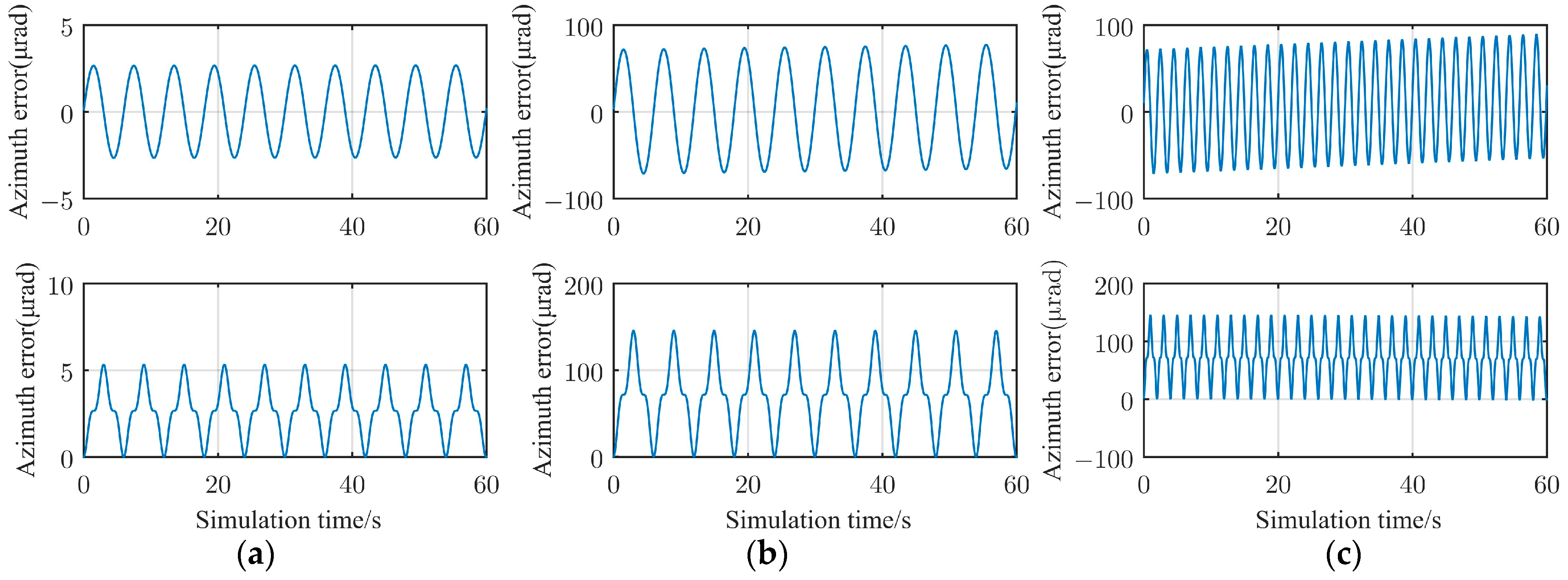
| Conical Motions. | Attitudes | Calculation Error (µrad) |
|---|---|---|
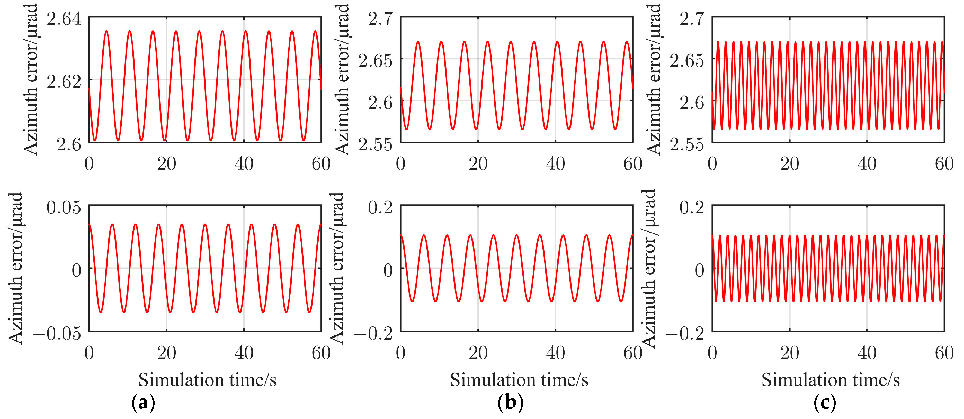
| (a) a = 1°, ω = 60°/s | Azimuth | 2.7 |
| Pitch | 5.3 | |
| (b) a = 3°, ω = 60°/s | Azimuth | 77.3 |
| Pitch | 145.4 | |
| (c) a = 3°, ω = 180°/s | Azimuth | 89.4 |
| Pitch | 145.6 |
Disclaimer/Publisher’s Note: The statements, opinions and data contained in all publications are solely those of the individual author(s) and contributor(s) and not of MDPI and/or the editor(s). MDPI and/or the editor(s) disclaim responsibility for any injury to people or property resulting from any ideas, methods, instructions or products referred to in the content. |
© 2023 by the authors. Licensee MDPI, Basel, Switzerland. This article is an open access article distributed under the terms and conditions of the Creative Commons Attribution (CC BY) license (https://creativecommons.org/licenses/by/4.0/).
Share and Cite
Wang, L.; Zhang, L.; Meng, L.; Bai, Y. Numerical Calculation for the Line-of-Sight Attitudes of Multi-Address Transceivers without 2:1 Transmissions for Space Laser Communication Networking. Electronics 2023, 12, 1575. https://doi.org/10.3390/electronics12071575
Wang L, Zhang L, Meng L, Bai Y. Numerical Calculation for the Line-of-Sight Attitudes of Multi-Address Transceivers without 2:1 Transmissions for Space Laser Communication Networking. Electronics. 2023; 12(7):1575. https://doi.org/10.3390/electronics12071575
Chicago/Turabian StyleWang, Lihui, Lizhong Zhang, Lixin Meng, and Yangyang Bai. 2023. "Numerical Calculation for the Line-of-Sight Attitudes of Multi-Address Transceivers without 2:1 Transmissions for Space Laser Communication Networking" Electronics 12, no. 7: 1575. https://doi.org/10.3390/electronics12071575