1. Introduction
The phenomenon of dynamic chaos has been actively studied since its discovery in the mid-1960s. For the first 20 years, this phenomenon was explored in detail, with examples in various fields of science and nature. Many amazing properties of dynamic chaos were discovered, and the possibility of synchronizing two or more dynamic chaotic systems certainly was one of the most promising avenues of research. It was this property that caused the first interest in chaos as a potential information carrier. Although the first communication schemes that were based on chaotic synchronization turned out to be ineffective in terms of noise immunity [
1,
2,
3,
4,
5,
6,
7,
8,
9,
10,
11,
12], they initiated the research on dynamic chaos application to communications. It turned out that dynamic chaos has a number of attractive features if considered from a data transmission point of view, including: potential to obtain complicated oscillations using electronic devices with a simple structure; ability to create a lot of different chaotic modes in a single device; the control of chaotic modes with the help of system parameters changes; large information capacity; the diversity of information input methods into chaotic signals; modulation speed increase relative to regular signals modulation; the possibility of self-synchronization of the transmitter and receiver; non-traditional multiplexing methods; and confidential messaging.
These features stimulated new efforts to research methods and approaches for using chaotic signals in communications. The potential candidates are differential methods of communication [
13,
14,
15] and energy reception [
16,
17,
18]. These approaches give us an opportunity to use such features of chaotic signals as wideband (ultra-wideband), which according to the Shannon capacity theorem provides channel information capacity proportional to its bandwidth, and the possibility to use spectrum spreading of the information signal during the transmission. This is important for the practical realization of communication systems working under a real physical environment.
It is important to note that there have been a number of examples of dynamic chaos applications used for communication in different physical environments: high frequency cables and free space (in radio communication) [
16,
17,
18], optical fiber (laser communication) [
19,
20,
21], water environment (communication using ultrasonic chaos), [
22,
23] etc.
At the same time, numerous studies have been done on chaotic signals as information carriers for communication systems, and they show that there is a significant gap between potential information possibilities (mentioned above) of communication systems based on dynamic chaos, and their practical implementation.
Thus, within theoretical studies, one popular differential chaos shift keying (DCSK) communication scheme requires a delay line with characteristic times determined by the duration of the sent bits. For example, if the transfer rate of the line is 0.5 Mbit/s, then the delay should be around 1 μs. One can create such a delay in analogue radio systems using microwave cable, but the length of this cable reaches about 200 m. In fact, a direct chaotic communication (DCC) scheme with energy reception is the only practically implemented scheme in wireless chaos-based communication systems [
24,
25,
26]. The limited possibilities of the practical applications of the present theoretical schemes based on dynamic chaos have held up the development of chaotic communications, and show the necessity of new solutions that are capable of overcoming these limitations.
In this article, the new direct chaotic differential communication (DC2) scheme for information transmission using dynamic chaos is considered and investigated in terms of its noise immunity. The time delays used in this scheme, unlike the DCSK scheme, do not exceed 10 ns for the chaotic signal bandwidth of 100 MHz and 1 ns for 1 GHz bandwidth (the cable length reaches 3 m and 0.3 m accordingly). Moreover, this scheme has extended possibilities for the multiple access modes organization compared to DCC system.
The name of the scheme reflects its main features: direct chaotic means that a chaotic signal is formed and modulated directly in the radio (microwave) frequency band where the wireless communication is performed; differential means that both reference and information signal waveform are transmitted through the communication channel.
Chaotic radio pulses are used in the DC2 scheme as information carriers; that allows us to customize processing gain (degree of spectrum spreading) by changing the length of the pulses, and to fight multipath propagation by using the guard intervals. It is supposed that direct chaotic transceivers are mostly based on wideband and ultra-wideband chaotic signals.
The structure of the article is as follows. The chaotic signals are considered and presented as effective signals for spectrum spreading in
Section 2. In
Section 3, the main existing incoherent communication schemes based on chaotic signals are considered, including their possibilities and limitations in terms of their practical usage. A direct chaotic differential communication scheme used for information transmission is described in
Section 4. Analytical estimates of DC
2 scheme noise immunity in additive white Gaussian noise channel are presented in
Section 5.
Section 6 is devoted to statistical simulation of noise immunity for the considered communication scheme. Finally, in the concluding section there is a discussion of the obtained results and possible directions of the future investigations.
2. Spectrum Spreading Signals
Unlike narrowband signals, the power of which is concentrated within a frequency band approximately numerically equal to the data rate, a spread-spectrum signal “smears” its power over a much wider frequency region [
27,
28,
29]. As a result, the average spectral density is much lower and the signal is easily hidden in the background noise. Therefore, without preliminary (a priori) knowledge of the structure and the parameters of the communication system, it is not so easy to detect the presence of the signal. Even if the presence is detected, the message is difficult to retrieve without additional information.
The quantitative characteristic of spectrum spreading is its processing gain K = ΔfΔt = Δf/R, where Δf is a frequency band occupied by the signal, Δt is the length of the bit and R is the rate of data transmission in bps (bits per second). Signals without spectrum spreading usually have ΔfΔt ~ 1, meaning K = 1.
The main requirements for spread-spectrum communication systems can be summarized as follows: the frequency band of the transmitted signal is much wider than the data rate; the bandwidth of the transmitted signal is independent of the data rate; and the received signals can be demodulated, in particular, by correlating them with a copy of the signal used to spread data in the transmitter.
Initially, spectrum spreading technologies employed two schemes: spreading with a direct spreading sequence (DSS) or frequency hopping (FH) [
27,
28,
29]. Later, they were supplemented by a “chirp”, i.e., a frequency-modulated impulse, the carrier frequency of which is swept over a certain wide band over the pulse length. This technology is in use, for instance, in low-power long-range networks such as LoRaWAN [
30].
The bandwidth of the carrier signal by itself does not characterize the signal in terms of spread spectrum. For example, an ultra-wideband ultrashort pulse has a signal processing (or base) about K = ΔfpΔtp = 1, where Δfp is the bandwidth of the ultrashort pulse, and Δtp = 1/R is its length, i.e., it is an ultra-wideband yet not spread-spectrum signal because its bandwidth is the same as its bitrate. However, a train of M ultrashort pulses of pseudo-random polarity, used to transmit one bit of information, is a spread-spectrum signal, and its processing gain is equal to M, since the length of the bit for this signal equals Tb = ΔtpM and K = ΔfpTb = M.
The idea of spectrum spreading follows from Shannon’s relation for the channel capacity
where
C is the channel capacity in bits per second;
W is the channel bandwidth in Hertz;
N is the noise power; and
S is the signal power. Expression (1) relates the ability to transmit information through the channel without errors to the value of the signal-to-noise ratio (SNR) in the channel and the frequency bandwidth.
Thus, let
C be the necessary bit rate, then proceeding from binary to natural logarithms we obtain
and for small values of SNR, e.g.,
(since we consider noise-immune systems), expanding the logarithm into a series and using the first expansion term, we have
That is, for any given
SNR, an arbitrarily low information error rate can be achieved by means of increasing the communication bandwidth
W. For example, if we want a 10-kbps channel in which noise is 100 times (20 dB) above the useful signal, then the channel bandwidth must be
In practice, there are several ways of putting information into the spread-spectrum signal. The most common way is to use a spreading modulation. Chaotic signals, which are inherently wideband, are natural candidates for spreading the frequency spectrum of narrowband information. Encoding information with chaotic fragments provides spread-spectrum signals that have a wider bandwidth and lower spectral density compared to the original information signals. The encoded signal maintains all the advantages of the spread-spectrum signals, such as difficulty of detection, without information about the system, immunity to multipath fading, to interference, etc. Moreover, due to high sensitivity to initial conditions and variation of the parameters, a large number of different spreading signals (waveforms) can be easily produced. Chaos is therefore an inexpensive and versatile solution for spread-spectrum communication systems.
3. Non-Coherent Communication Using Chaotic Signals
In the late 1990s and early 2000s, several communication schemes were proposed based on dynamic chaos without the use of chaotic synchronization. Among them, a DCC (Direct Chaotic Communications) scheme [
16,
17,
18,
24,
25,
26,
31,
32] (
Figure 1), as well as a COOK (Chaos On-Off Keying) scheme, which is closely related to DCC [
11,
14,
33], belong to the first type of schemes (with energy reception), whereas a DCSK (Differential Chaotic Shift Keying) scheme [
11,
13,
14,
15,
34] and a CDSK (Correlation Delay Shift Keying) scheme [
15] belong to differential methods. In terms of statistical characteristics, these systems were close to classical narrowband non-coherent communications.
The name of direct chaotic communications (DCC) reflects its main feature: a chaotic signal is formed and modulated directly in radio (or microwave) frequencies, where the wireless communication occurs.
Chaotic radio pulses are used as an information carrier in DCC scheme, what makes it possible to customize the processing of the information signal (the degree of spectrum spreading) through the pulse length and fight multipath fading by using guard intervals. Direct chaotic wireless transceivers mainly use wideband and ultra-wideband chaotic signals.
The structure of a DCC scheme transmitter is shown in
Figure 1: a source of chaotic radio pulses (SCR) forms the stream of chaotic radio pulses with guard intervals between them (graph “
a” in
Figure 1c). On-off keying (OOK) modulation is used in the variant presented in
Figure 1c (graph “
b”). Transmission of “1” happens if there is a chaotic pulse in a corresponding position, transmission of “0” occurs if there is no such pulse (graph “
c” in
Figure 1c). Energy reception is used in the receiver (
Figure 1b), which includes sequential connection of square law detector, low pass filter with cutoff frequency being in accordance with the frequency of pulse positions, and threshold device that determines if “0” or “1” was received.
The DCSK communication scheme is shown in
Figure 2. Each transmitted symbol of
Tb length is presented in the modulator by two sequential fragments of chaotic signal (
Figure 2a). The first one is a reference fragment and the second one carries data (data fragment). The data fragment is identical to reference one if it is required to transmit “+1”, and the inverted version of the reference fragment is used as a data fragment if one has to transmit “−1”. The reference fragment is usually sent in the first part of the symbol period, whereas the data fragment is sent in the second part of the symbol period. The required positions of these fragments are realized with the help of chaotic signal modulation in the upper line of the scheme and its connection to the channel for a delay time
Tb/2 of reference signal. The correlation between reference and data fragments is calculated in the receiver (
Figure 2b). This is performed by the comparison of input signal and its own version delayed by
Tb/2, as is shown in
Figure 2b. The result at the output of the correlator at the end of the symbol duration is a number which sign corresponds to the sign of the transmitted symbol. Finally, a threshold device set to “0” is used in order to determine the sign of this number.
Up to date, only DCC has been experimentally implemented. As for differential chaotic communications, even DCSK, the best of them, had problems with practical implementation.
Formally, both DCC and DCSK belong to spread-spectrum communication systems. However, due to the lack of a copy of the waveform on the receiving side, a noisy waveform transmitted through the channel is used in the receiver, whose statistical characteristics deteriorate, compared to a “truly coherent” receiver of spread-spectrum signals. This is especially noticeable for the signals with large or very large processing gains.
At the same time, the effect of signal accumulation still works, which allows them to extract a useful signal even under the noise.
In this paper, we consider a scheme of Direct Chaotic Differentially Coherent (DC
2) communications, in which chaotic radio pulses are used as information carrier [
35,
36,
37]. From the viewpoint of practical implementation, differential communications based on DC
2 differ from the DCSK [
11,
12,
13,
14] in that their time delays are significantly shorter.
4. Differential Communications Using Chaotic Radio Pulses
Chaotic signals used in DC2 scheme as information carriers have a noise-like waveform and a rapidly decaying autocorrelation function. These are the key features used in the discussed scheme of differential communications. The frequency bandwidth of chaotic radio pulses is determined by the bandwidth of the original chaotic oscillations, and within a wide range of the pulse length variation, it does not depend on the pulse duration.
If the duration of the chaotic radio pulse is , then the power spectrum of the flow of chaotic radio pulses is practically indistinguishable from the power spectrum of the original chaotic oscillations. The signal processing gain , so an increase of the length of the chaotic radio pulse leads to an increase of its processing gain K.
An important characteristic of DC2 is the time of autocorrelation of the chaotic radio pulse, which is inversely proportional to the frequency bandwidth of the chaotic signal . If a chaotic radio pulse is shifted relative to itself for a time longer than the autocorrelation time, then these two radio pulses can be considered uncorrelated. This feature underlies the DC2 scheme for modulation and data transmission.
The discussed communication scheme refers to a type of differentially coherent reception scheme where, unlike the scheme with coherent receiver, a copy of the transmitted signal is not formed in the receiver, but is sent over the radio channel.
To transmit data in DC2, a modulated chaotic radio pulse and its non-modulated copy are emitted to the channel with a delay τ (between them) greater than the time of autocorrelation. In the receiver, the modulated radio pulse is correlated with its delayed non-modulated copy. In the process of modulation, to transmit symbol “1”, the chaotic radio pulse is emitted unchanged, whereas to transmit symbol “0”, the chaotic radio pulse is multiplied by −1. Thus, after differentially coherent reception, pulses of positive and negative values appear in the receiver.
The transmitter (
Figure 3a) is composed of a source of chaotic radio pulses (SCR), a modulator controlled by an external information signal, a time delay
τ exceeding the autocorrelation time of the chaotic signal, and an adder.
The source of chaotic radio pulses generates pulses of duration Tp; the intervals between the pulses, the so called guard intervals, have duration Tgi. The total duration of the transmitted bit Tb is the sum of the durations of the pulse and the guard interval. Each impulse goes to two channels. In the first channel, it is modulated by an information signal multiplying by ±1, and in the second channel it is delayed by time τ. Multiplication by +1 corresponds to transmitting symbol “1”, and multiplication by −1 corresponds to transmitting “0”. After that, the signals are added, and the resulting signal enters the communication channel. The length of the pulse in a channel is equal to Tr = Tp + τ.
The receiver (
Figure 3b) consists of a divider, a delay for time
τ, a multiplier, a low-pass filter, and a threshold device. The received signal is divided in half and fed into two channels. Signal waveforms in various nodes of transmitter are presented in
Figure 4. In the first channel, the signal (
Figure 4a) after divider is multiplied by “−1” (
Figure 4c) or “1” (
Figure 4d), whereas in the second channel the signal is delayed by time
τ (
Figure 4b), after which the signals from both channels enter the multiplier. Note that the duration of the pulse after the multiplier is equal to
Tp. The pulse after the multiplier (
Figure 4e) enters the low pass filter. Then the signal is fed to a threshold device with zero threshold. If the signal is greater than zero, then the threshold device indicates the reception of symbol “1”; otherwise, symbol “0” is received.
Let
Sk(
t) be the
kth chaotic pulse generated by the source of chaotic radio pulses (the pulses must be indexed, because they all are different due to their chaotic nature) and
be the value of the modulating information signal. When transmitting
kth binary information symbol, the signal at the output of the transmitter is:
In the receiver, in the absence of noise at the multiplier output, the impulse, corresponding to
kth information symbol, goes to the integrator, after which it takes the form:
where
The component θk(t) of signal (8) is the noise generated by the DC2 scheme itself. Since the delay time τ exceeds the autocorrelation time, all components of θk(t) are significantly smaller compared to the first term in expression (8), which is the useful signal. Thus, the sign of αk (“+” or “−”) also determines the sign of Zk(t). The signal from the integrator output is fed to the decision block, where it is compared with the zero threshold. Thus, its sign determines the output binary information symbol.
5. Analytical Estimates of Noise Immunity in AWGN Channel
Analytical noise immunity estimates for DC
2 differential scheme are obtained in [
25] under the assumption that fluctuation noise with Gaussian distribution of instantaneous values and a constant spectral density is added to
kth signal at the receiver input:
The error probability for each received bit is given by:
where
Here Nc is the spectral density of the chaotic signal; ΔF is the chaotic signal bandwidth; and N0 is the spectral density of noise.
Analysis of the analytical form of the error probability gave an interesting asymptotic property, namely, as SNR tends to infinity, the error probability tends not to zero, but to a certain limit:
Analytical noise immunity estimates provide us with the strong basis for calculations in the design of the DC2 communication scheme. However, they have certain limitations that can be overcome by statistical simulation in those cases where it is necessary to find out, e.g., the limits of applicability of analytical estimates.
Such cases include questions of the effect of the statistical characteristics of a chaotic signal on the noise immunity. The problem is that the above analytical estimates are obtained for the case of a Gaussian distribution of the chaotic signal, i.e., in principle, spikes of an arbitrarily large amplitude are possible for such a signal. However, real chaotic signals are limited. The effect of the limited-value signals compared to signals with Gaussian distribution can be conveniently considered by means of direct statistical simulation using signals with corresponding probability distributions of instantaneous values.
6. Statistical Simulation of Noise Immunity
Below, for the numerical analysis of the noise immunity of DC2 communication scheme, a discrete signal model is used. A time-discrete chaotic signal is formed of pseudo-random samples corresponding to three different distributions (normal, uniform, and telegraph), that represent typical cases of the distribution of instantaneous signal values.
According to this discrete model, continuous waveforms Sk(t) and Yk(t) are replaced by discrete samples Sk(i) and Yk(i), and the noise η(t) by noise samples η(i), where i is the number of the sample. Transition to these values is made with the substitute t = iTp/(2K) into Sk(t), Yk(t), and η(t). The sign of the signal at the output of the adder determines the symbol received: minus stands for “0” and plus means “1”.
To calculate the error probability, the original information signal and the signal at the detector output are compared for different values of Eb/N0 (ratio of the energy per bit to the noise spectral density).
Knowing the value of
Eb/
N0 and the processing gain, and measuring the power at the output of the transmitter, one can calculate the necessary value of the noise power for various cases:
where
is the signal power at the transmitter output,
is the noise power at the receiver input, and
K is the processing gain.
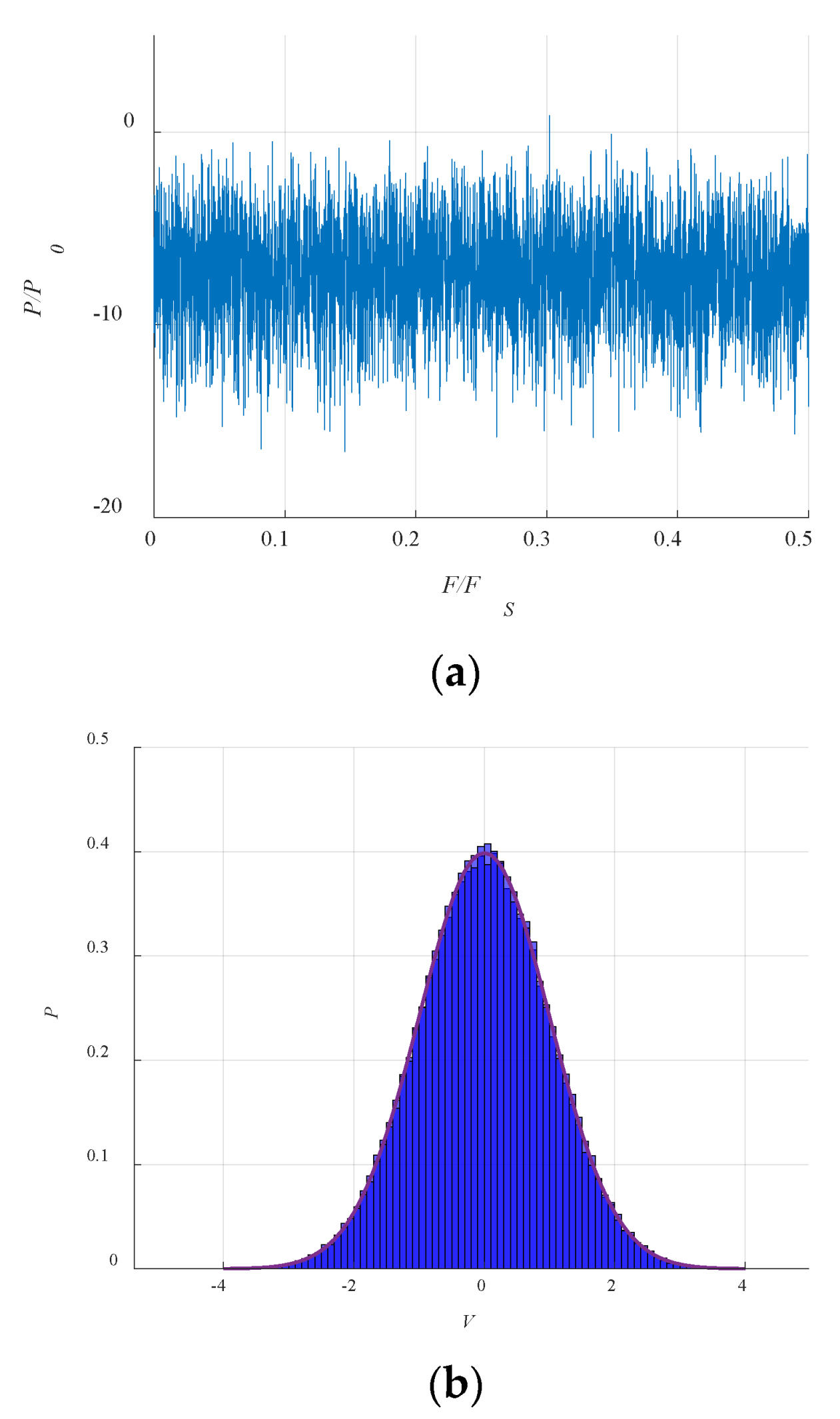
Thermal noise in the communication channel is modeled by random samples with a normal distribution. The power spectrum of the random signal sampled at frequency
Fs and its distribution are shown in
Figure 5. Statistical signal distribution is given in
Figure 5b. The noise signal bandwidth is matched with the bandwidth of the chaotic signal, because discrete forms of both are obtained with the same sampling frequency.
All the simulations were performed in MATLAB. One can see the parameters used for the modeling in
Table 1.
6.1. Simulation for the Noiseless Channel
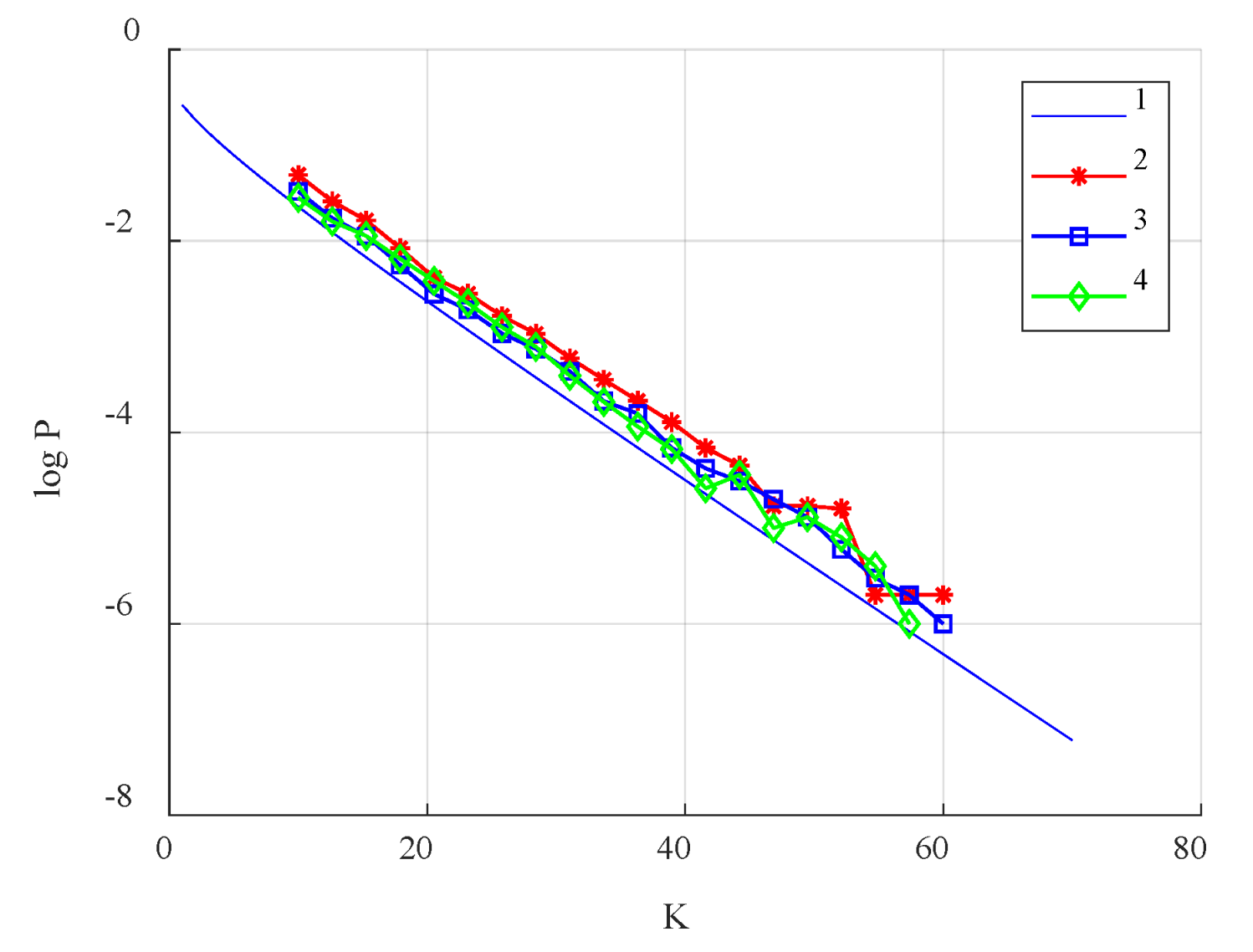
The DC
2 communication scheme was simulated according to the model described above. As a result, the bit error probability as a function of the processing gain was obtained (
Figure 6). As can be seen from this graph, the communication system starts working at error level
p = 10
−3 at high values of the processing gain (starting from
K ~ 25), and with increasing
K one can expect lower values of the error probability per bit
p.
The analytical estimate of the bit error probability as a function of the ratio
Eb/
N0 (as mentioned in
Section 5 of this article and presented in Equation (10)) is in good agreement with the simulation results of this dependency (
Figure 6).
6.2. Simulation for the AWGN Channel
Let us proceed to statistical simulation of the DC
2 communication scheme in the presence of noise in the communication channel and then compare the results obtained with analytical estimates 6–8 from [
35,
36,
37].
Statistical numerical simulation was carried out for the values of the processing gain K = 5, 10, 15, 20, 50, 100, 200, 300, 500, 10,000.
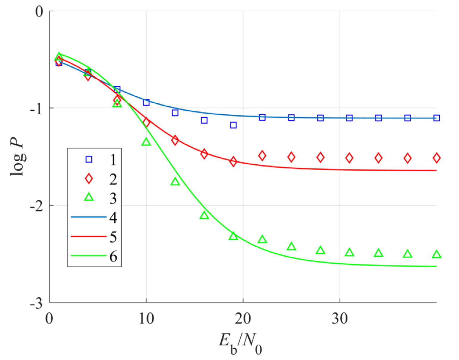
First, we simulated the system for the model of chaotic signal with Gaussian statistic. The results for small values of the processing gain
K = 5, 10, and 20 are presented in
Figure 7.
As can be seen in
Figure 7, for
K = 5, 10, and 20 it is impossible to achieve the error probability
p < 10
−3 at any ratio of
Eb/
N0.
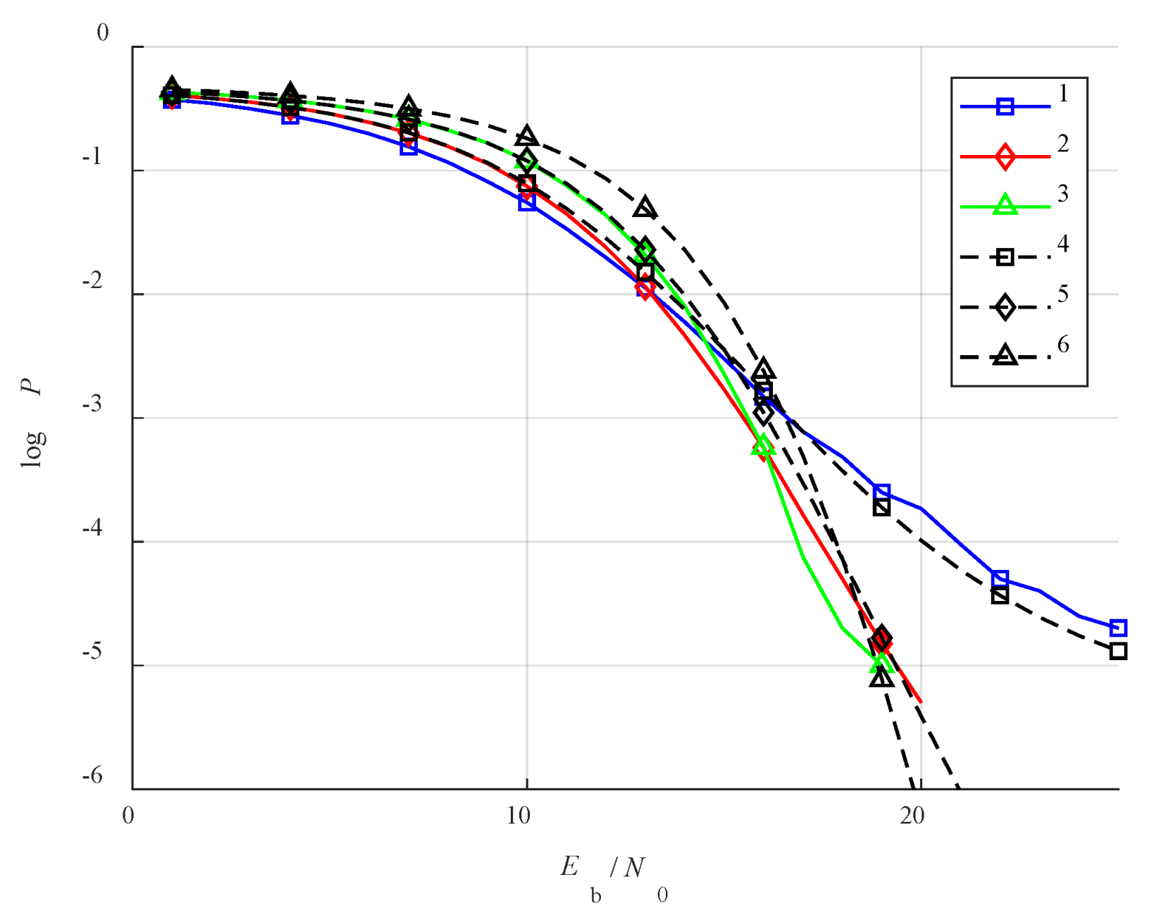
Numerical experiments with other types of distributions of the chaotic signal model, namely, uniform and telegraph, show that even with these signal distributions the error probability
p < 10
−3 is not achieved at small values of
K. Note that at low values of
K the models of a chaotic signal with telegraph and uniform distributions are more noise-resistant by comparison to the model with a Gaussian distribution (
Figure 8).
Real chaotic signals have limited amplitude and their statistic has no long tails, as with a Gaussian distribution. Therefore, they better fit the results obtained with a uniformly distributed signal or a random telegraph signal.
The simulation results indicate that with an increase in the processing gain, the dependence of the chaotic signal model on the distribution type disappears. Therefore, when evaluating performance, one can limit oneself to one type of signal, e.g., a signal model with a Gaussian statistic.
With an increase in the processing gain to
K = 50, the minimum value of
Eb/
N0 that provides error probability
p < 10
−3 is 15.3 dB (
Figure 9).
As
K increases, the bit error probabilities as functions of external noise for different distributions are close to each other and fall on the same curve (
Figure 10).
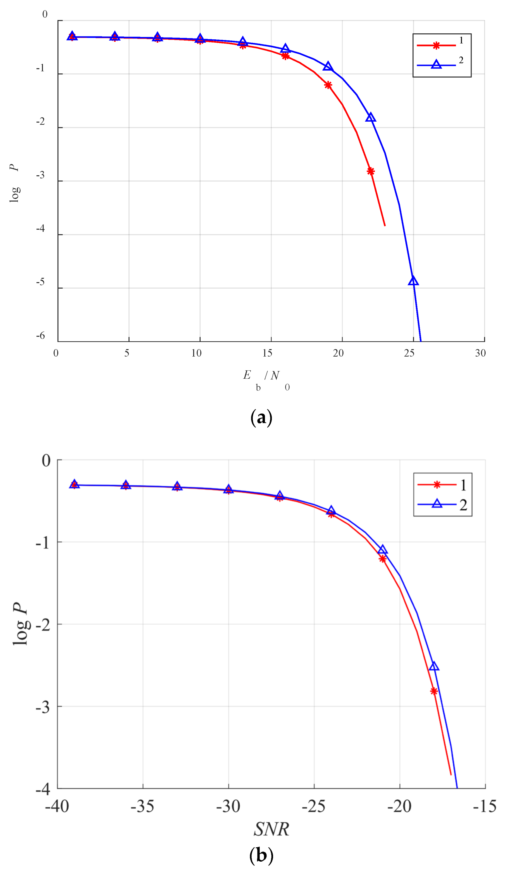
Of particular interest is the study of the performance of the communication system at very high processing gains. For instance, in
Figure 11 the simulation results are presented for the processing gain
K = 10,000. They indicate that in this case the communication system can operate with the bit error probability
p = 10
−3 at
Eb/
N0 = 22.2 dB. However, if we consider the dependence on SNR (
Figure 11b), we can see that due to the high processing gain, the required SNR in this case is less than −17 dB, which means that the communication system is operational at a signal level much lower than the noise level in the communication channel.
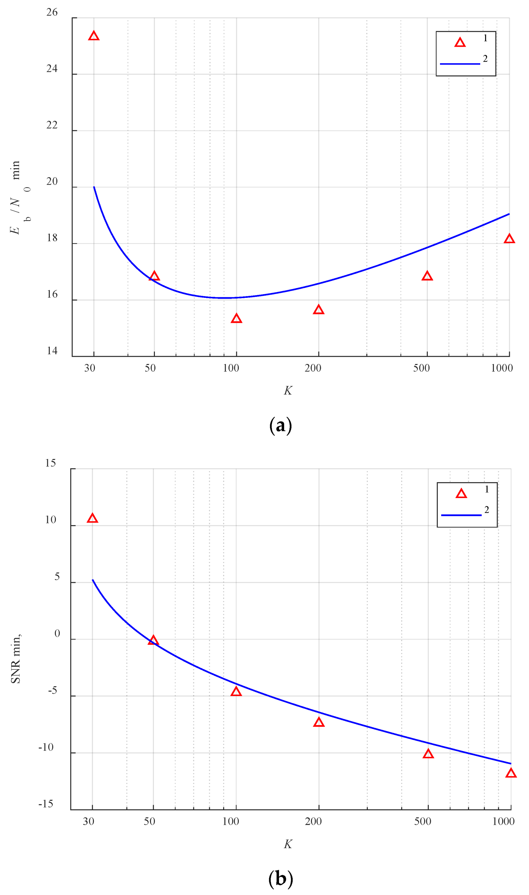
We also carried out a computer simulation in order to find the optimal value of the processing gain that provides a given bit error probability (in this case,
p = 10
−3) at the minimum value of
Eb/
N0 (
Figure 12).
The results presented in
Figure 12 show that the plot of
Eb/
N0 vs.
K has an extreme point at
K = 100, where the minimum value of
Eb/
N0 = 15.3 dB is reached. With a further increase in K, the value of
Eb/
N0 that provides the error probability
p = 10
−3 also increases, which makes the system operation with such parameters less energy-efficient. However, note that according to
Figure 12b, with an increase in the value of the processing gain
K, the value of SNR necessary to provide the error probability
p = 10
−3 decreases, which gives an advantage to the signals with a large base in the direct chaotic differential communication scheme in terms of privacy and operation below the noise.
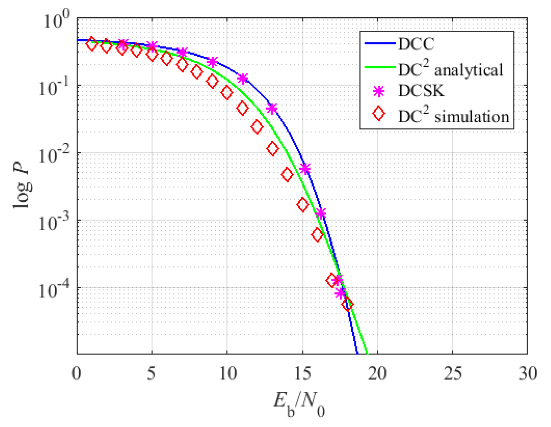
Summing up the obtained results, comparison of the DC
2 scheme with the DCC and DCSK schemes shows (
Figure 13) that its characteristics, in terms of BER for AWGN channel with high values of processing gain (
K > 50), are similar to the DCC and DCSK schemes. However, according to the above, the DC
2 scheme is more suitable for practical application than DCSK due to the possibility of using significantly shorter time delays. Moreover, one can expect more options in multiple access implementation for DC
2 scheme compared to DCC scheme. However, both of these advantages have to be verified in future investigations.
7. Conclusions
In this paper, statistical characteristics of the new differential communication scheme based on chaotic radio pulses are investigated. The time delays used in this scheme are determined by the decay time of the autocorrelation function of a chaotic signal. This is the principal difference between the proposed scheme and the classical differential DCSK scheme, where the length of the transmitted bit determines time delay. The system is simulated numerically, and the simulation results are compared with previously obtained analytical estimates of the bit error probability depending on the ratio of the signal energy to the spectral density of the Gaussian noise. In addition, research was conducted on regularities associated with the use of chaotic signals with different statistical distributions of instantaneous values.
It is shown that having high processing gain (K > 30), the communication scheme under consideration operates effectively both in a channel without fluctuation noises and in a channel with additive white Gaussian noise. With the increase of the processing gain the noise immunity dependence on the particular choice of the statistical distribution of chaotic signal instantaneous values is leveled. Taking into account that the scheme uses short delays, which do not depend on the processing gain of the used signal and are easily implemented, for example, on fragments of a high-frequency cable, the results obtained show good prospects for its application in a physical experiment.
The corpus of the results obtained forms the basis of the statistical theory of the DC
2 direct chaotic differential communication scheme. Research on the multiple access organization of the DC
2 scheme and its experimental validation could be promising directions for future research. One important aspect to mention is the problem of effective radiation of wideband and ultra-wideband chaotic signals in a physical experiment. There are different classical approaches as well as new ones [
38,
39] that could be implemented to tackle this problem.


