1. Introduction
Power electronics is a popular topic of research, being in constant evolution since its beginning [
1]. Over the past few years, with the constant evolution of new and improved power devices, many kinds of power converters have been developed for wide power applications. Regarding high-power applications, the efficiency of power converters is of paramount importance since the stress of the components is higher due to the magnitude of voltages and currents. As such, to overcome such limitations, a new family of power converters was introduced some decades ago, named the multilevel converters [
2]. Multilevel converters appeared in 1974 [
3] and have raised in popularity due to their characteristics and advantages, which include [
4,
5]: Reduction in power loss leading to better efficiency; Low dv/dt in the switching power devices; Reduction in the harmonic spectrum of the controlled variables; Low common mode voltage; Scalability to superior voltage and current levels. These advantages lead to the compactness of the power converters, i.e., the design of power converters with high power density, as well as the reduction of production costs.
Within the family of multilevel power converters, the modular multilevel converter (MMC) has been one of the most promising power converters for medium/high voltage applications compared to conventional multilevel converters. The MMC can reach voltage values up to 400 kV with power ratings of 1000 MW [
6], which makes this kind of converter very attractive from an industrial and academic point of view. In addition to the multilevel advantages, the MMC possesses some unique characteristics of its own, among others [
7]: Modular construction; Voltage and power scalability; Fault-tolerant operation; Simple redundancy due to the modular structure. However, the MMC also presents some disadvantages when compared to other power converters, such as the complex control required for balancing the submodules voltage and the existence of a circulating current that needs to be suppressed, otherwise, there will be an increase in device losses. These disadvantages result in a much more complex control system due to the number of variables being monitored.
The first MMC available commercially was installed in Transbay, a Siemens project in San Francisco in 2010 [
8,
9], and has been extended to a wide array of applications ever since, such as variable speed drives [
10,
11,
12,
13], power quality applications [
14,
15,
16,
17], renewable energy interface [
18,
19,
20,
21], railway power systems [
22,
23,
24], solid-state transformers [
25,
26,
27], and HVDC systems [
28,
29,
30,
31,
32]. There are several MMC topologies, mainly, regarding the different structures of the submodules, as well as their integration, each presenting its advantages and disadvantages [
33].
After this brief contextualization, this paper presents the development and experimental validation of a reduced-scale single-phase MMC applied to a railway static converter. As main contributions, it is important to highlight: (i) application of the MMC in railway static converter, used to interface the railway power grid with (although the MMC can be applied for several applications interfacing the power grid, the context of interfacing railways applications is different, since the power grid voltage is subdivided by the submodules); (ii) comparison regarding the possible power converters that can be used in the MMC submodules (e.g., in terms of number of output levels, number of switching devices, number of DC capacitors, DC fault blocking, and control complexity); (iii) utilization of the MMC to interface the power grid, by controlling the current in order to obtain a sinusoidal waveform, when operating in bidirectional mode, and independently of the power quality issues in the voltage of the main power grid; (iv) full development of a reduced-scale laboratory prototype, including all the details related with the power converter (e.g., dedicated drivers, dedicated protection circuits, voltage and current measuring and signal conditioning) and the control system (e.g., dedicated ADC external board, and digital c-code directly programmed in a DSP), as well as the necessary circuits and protections for interfacing the power grid; (v) experimental validation in laboratory with the MMC directly connected to the power grid, without the use of any kind of controlled power supply, which is relevant, since it was possible to control the MMC operating in bidirectional mode, both injecting and absorbing power from the power grid.
Based on the presented introduction, the paper is organized according to the following sections.
Section 2 presents the MMC topology configuration, contextualized with the different possibilities in terms of using distinct power converters.
Section 3 introduces the operation principle of the MMC considered in the scope of this project.
Section 4 presents the digital control algorithms for controlling the voltages and currents of the MMC.
Section 5 presents a set of considerable simulation results to contextualize the operation of the MMC when applied to a railway static converter.
Section 6 shows details of the implementation of the fully developed reduced-scale laboratory prototype.
Section 7 presents the main experimental results, in steady-state and transient-state, obtained with the laboratory prototype, which complements the simulation results and supports the main contributions of the paper. Finally,
Section 8 presents the conclusions.
2. MMC Topology Configuration
As the name suggests, an MMC is divided into submodules, which results in great versatility for the type of power converter. Among the most usual submodule configurations, three stand out: Half-Bridge (HB), Full-Bridge (FB), and Flying Capacitor (FC). This section presents these submodule topologies and their applications in static inverter topology.
2.1. Submodule Topologies
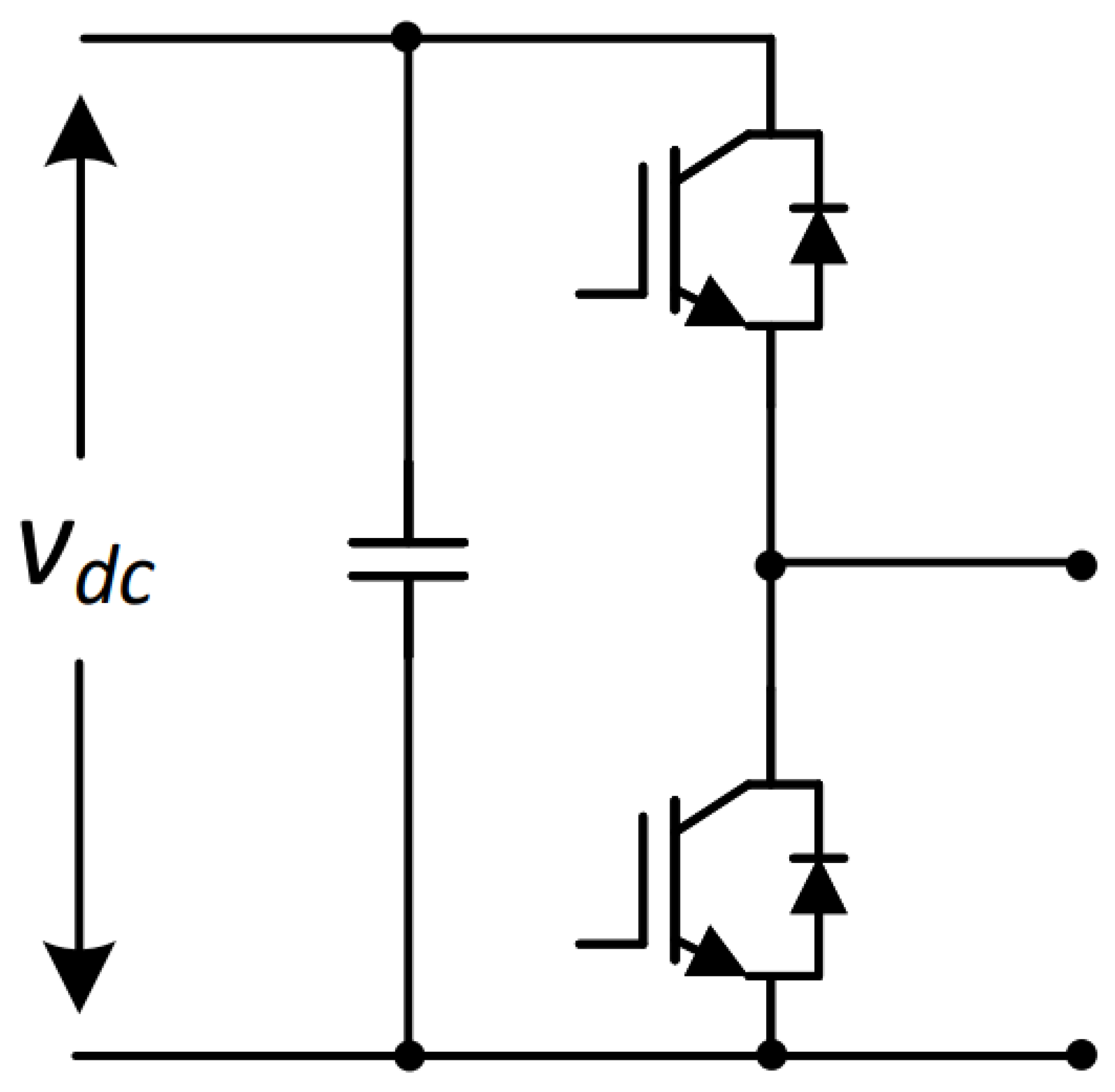
The HB submodule is composed of two switching devices with antiparallel diodes and a DC capacitor. The output voltage is composed of two levels: 0 and
vdc. The schematic of an HB submodule is presented in
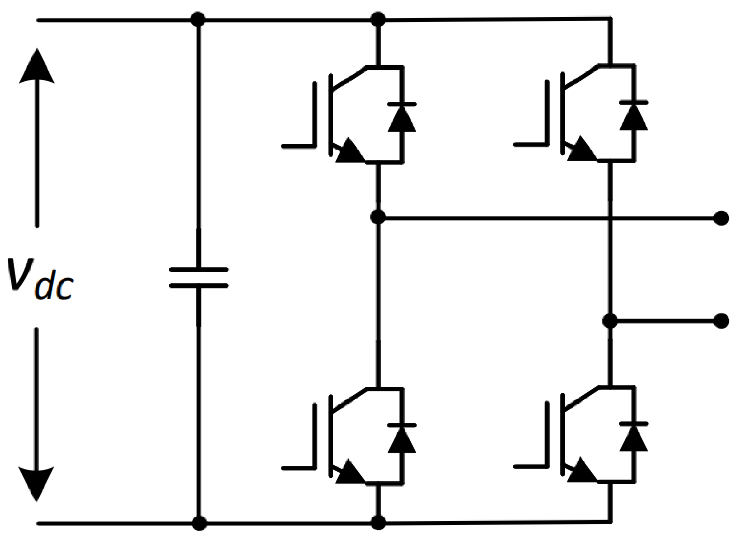
Figure 1. The FB submodule is composed of four switching devices with antiparallel diodes and a DC capacitor. The output voltage is composed of three levels: 0,
vdc, and −
vdc. The schematic of a FB submodule is presented in
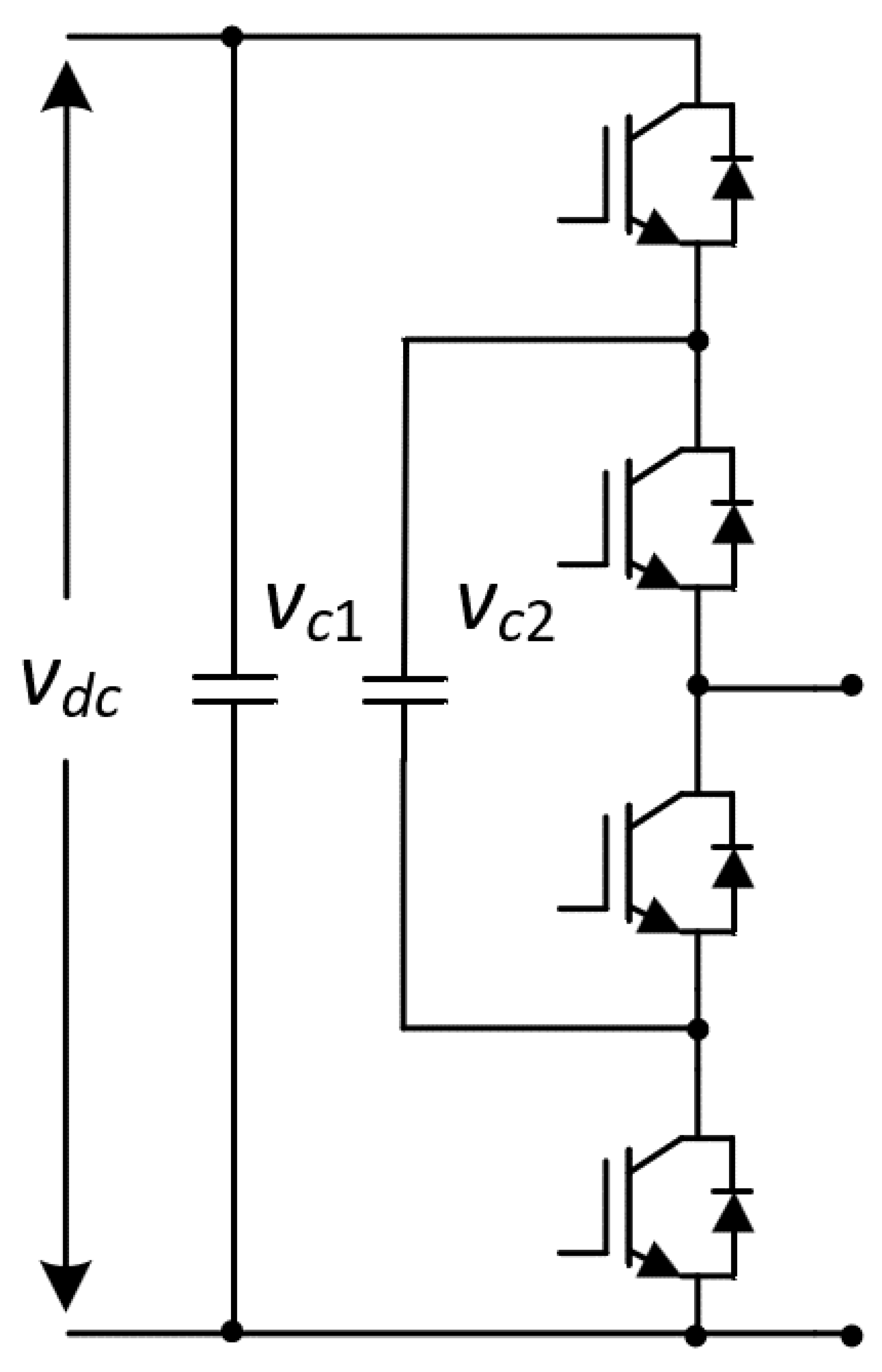
Figure 2. The FC submodule is composed of four switching devices with antiparallel diodes and two DC capacitors. The output voltage is composed of three levels: 0,
vc1, and
vc2. The schematic of an FC submodule is presented in
Figure 3.
Among all the submodules topologies, the HB is the most popular and commonly used in commercial products, due to its simple construction, with a straightforward design and control. Furthermore, in operation, only one switching device is in conduction at a time, resulting in low power losses and high efficiency. However, due to its simplicity and reduced number of semiconductors, the output value only takes positive values, so it cannot support DC fault blocking.
The FB submodule possesses a similar complexity in the design and control to the HB, however, possesses two more switching devices, which leads to higher losses, since there are two switching devices in conduction at the same time, thus reducing the efficiency of the submodule. Due to the capacity of outputting both positive and negative values, the FB can limit the current during eventual DC faults [
34].
The FC submodule possesses a more complex design and control than the HB and FB, requiring two DC capacitors with different rated voltages. In operation, a maximum of two devices are in conduction at a time, thus the efficiency and power losses are like the FB. Similarly to the HB, as the FC cannot have negative output values, it has no DC-fault blocking capability.
Table 1 presents a summary of the differences between these three types of submodules.
2.2. Static Inverter Topology
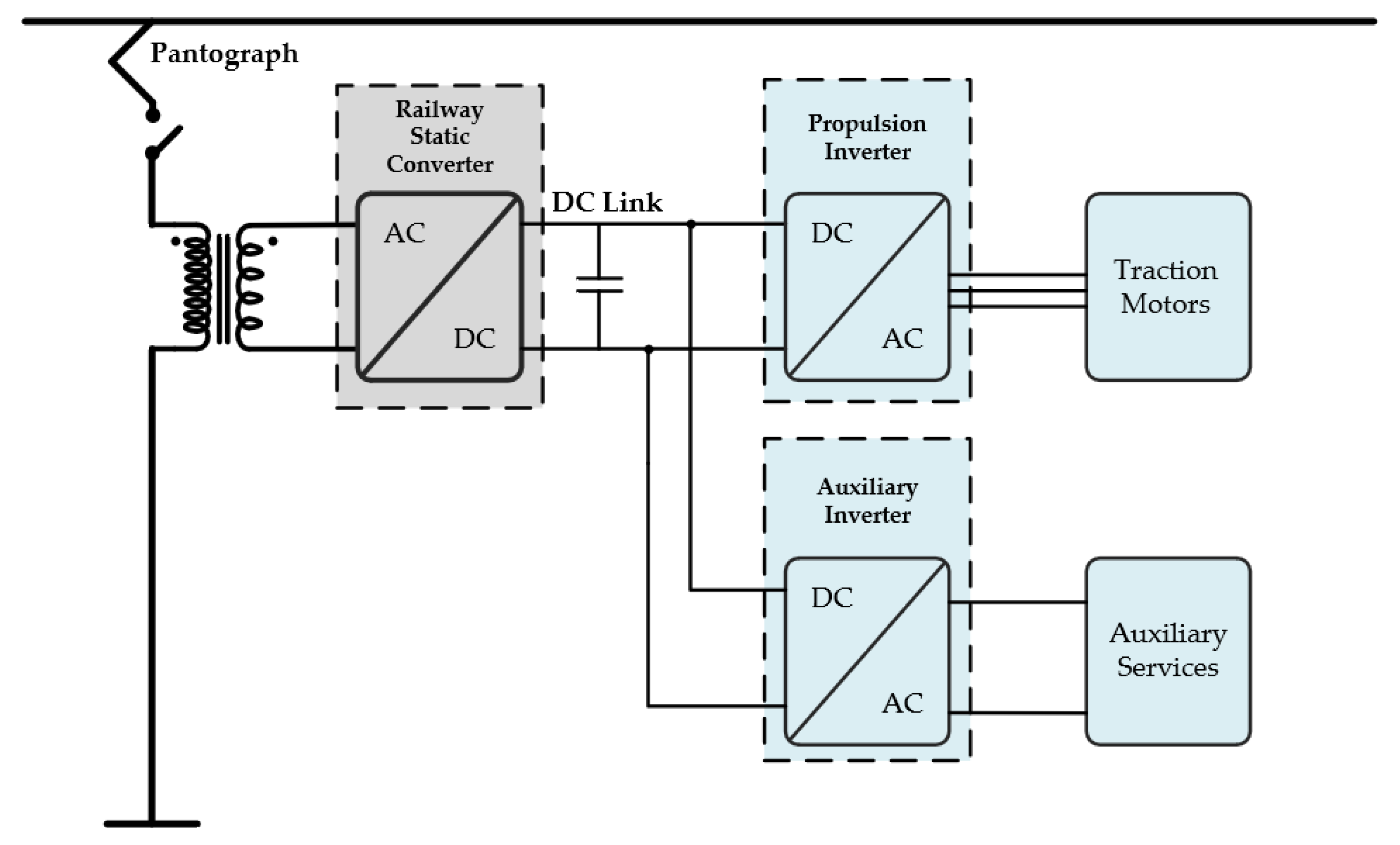
The electrification of a train goes through some power conversion stages, from the power lines to the powering of the traction electrical motors and the auxiliary services. The power is supplied to the train through a pantograph from the power lines (power grid). In
Figure 4 is presented a generic diagram of the power system of a train, consisting of an AC power line (15 kV or 25 kV), a pantograph, a circuit breaker, a high-power transformer, and three power converters. The same concept is used for trains powered in DC, without using the power transformer and the main converter here presented. The railway static converter is responsible for creating a DC link, which the propulsion inverter and the auxiliary inverter use as input voltage. Since the referred DC link is shared by both inverters, mainly due to the power required for the traction motors, the DC link suffers very high fluctuations. The propulsion inverter is a powerful power converter responsible for controlling the traction of electrical motors. The auxiliary inverter is responsible for supplying the necessary power for the auxiliary services.
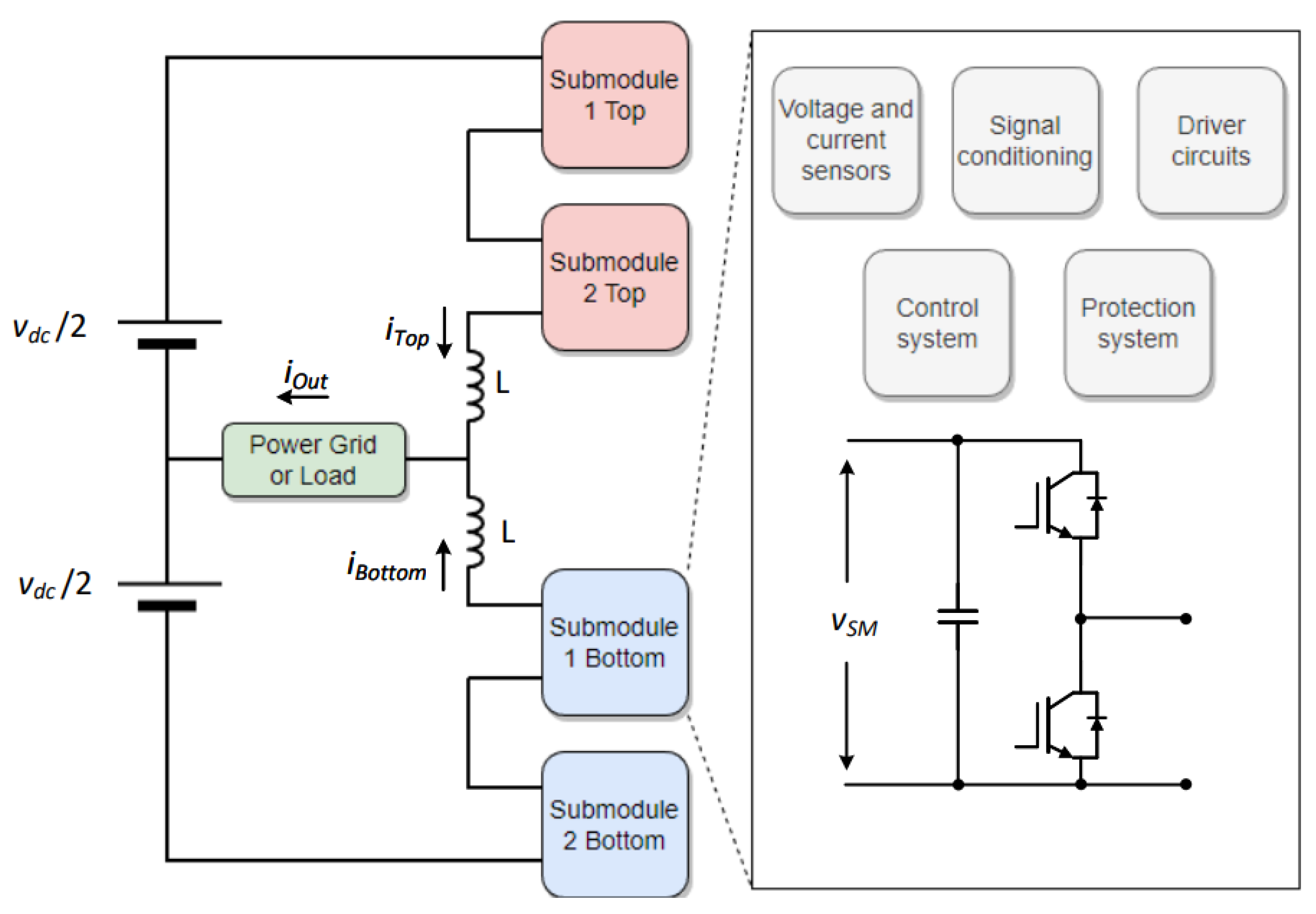
The focus of the present paper lies in the development of a static converter based on an MMC with half-bridge submodules. As a proof of concept for the interface of a single-phase multilevel converter with the electrical power grid, the selected topology is presented in
Figure 5.
The MMC is composed of a split DC-link and four half-bridge submodules. Each submodule is equipped with voltage and current sensors and respective signal conditioning. Recurring these sensors, it is implemented a protection system in both hardware and software, which is essential to ensure the good functioning of each submodule, as well as keeping the DC-link capacitors balanced.
3. Operation Principle of the Selected MMC Topology
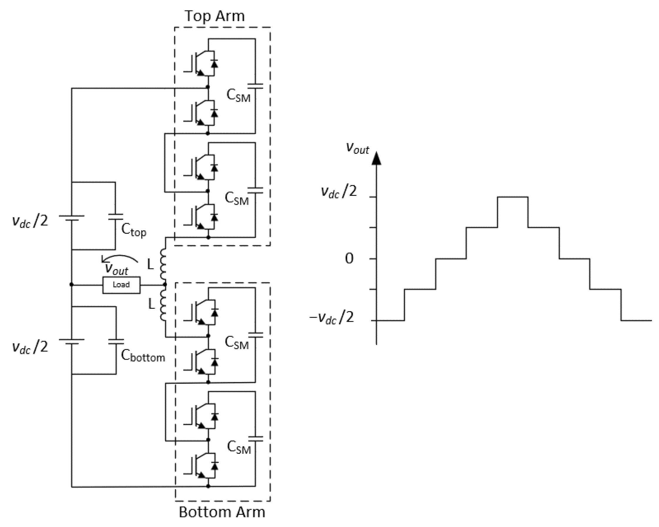
This section focuses on the presentation of the selected MMC topology, as well as the demonstration of its operation principle recurring to an electrical diagram. The MMC topology is composed of two half-bridge submodules in each arm of the converter, performing a total of four half-bridge submodules in the entire MMC.
Figure 6 presents the electrical diagram of the MMC topology, as well as the output voltage levels of the power converter.
Each submodule is composed of two IGBTs, where only one conducts at a time. When the upper IGBT conducts, the submodule is considered active and when the lower IGBT conducts, the submodule is considered bypassed. The activation of the upper submodules results in a positive voltage, while the activation of the lower submodules results in a negative voltage. The output voltage of the MMC is the sum of both arm voltages, considering the voltage division in the coupling coils. The number of voltage levels in the output of the MMC using this topology is equal to
N + 1, where
N refers to the number of submodules. As such, there are five voltage levels possible on the output of the converter: −
vdc/2, −
vdc/4, 0,
vdc/4, and
vdc/2. The production of some levels can be made using a different combination of submodules active and bypassed, which created redundant states, which are useful for the balancing of the voltages across the capacitors of the submodules. The synthesis of the different output levels is presented in
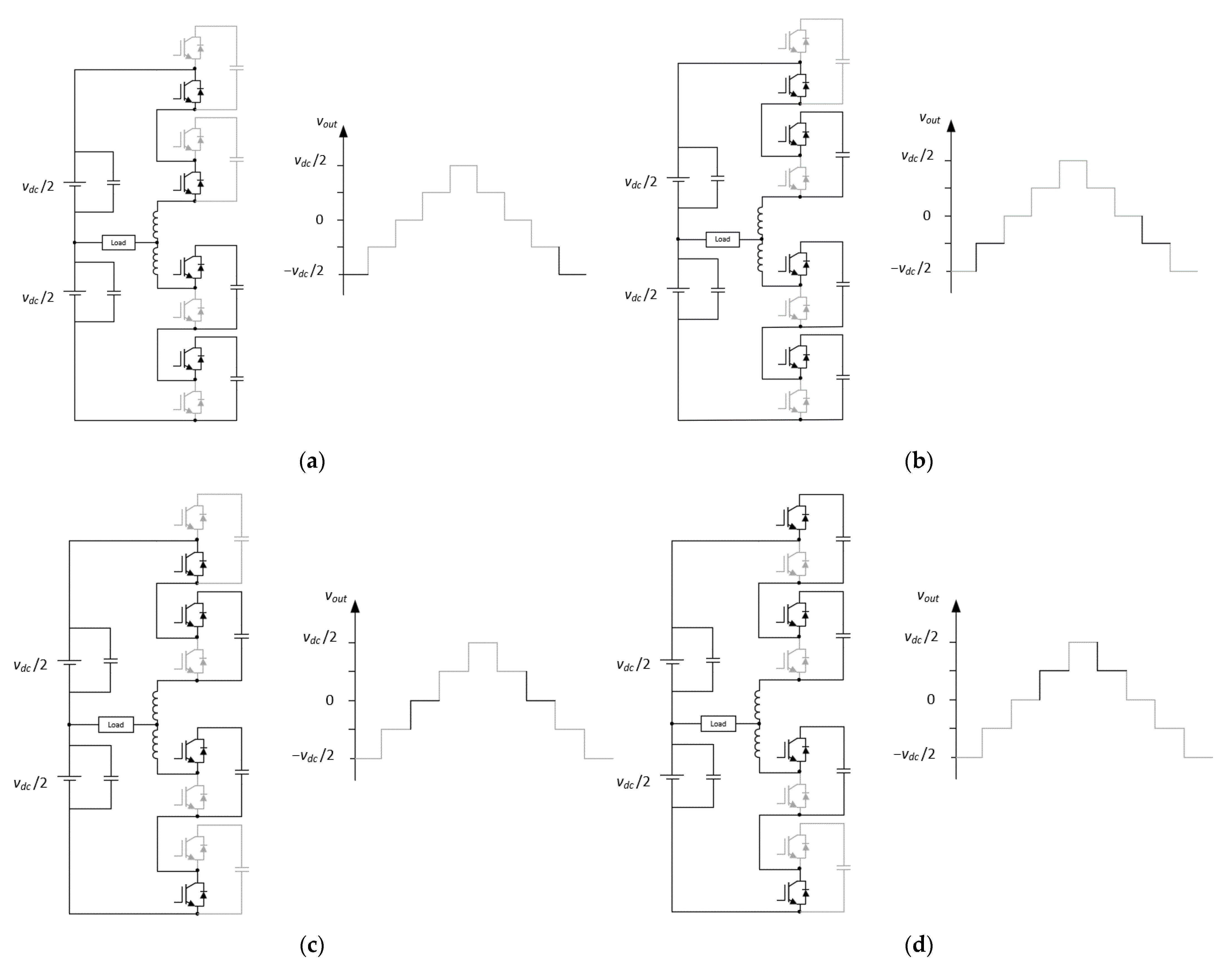
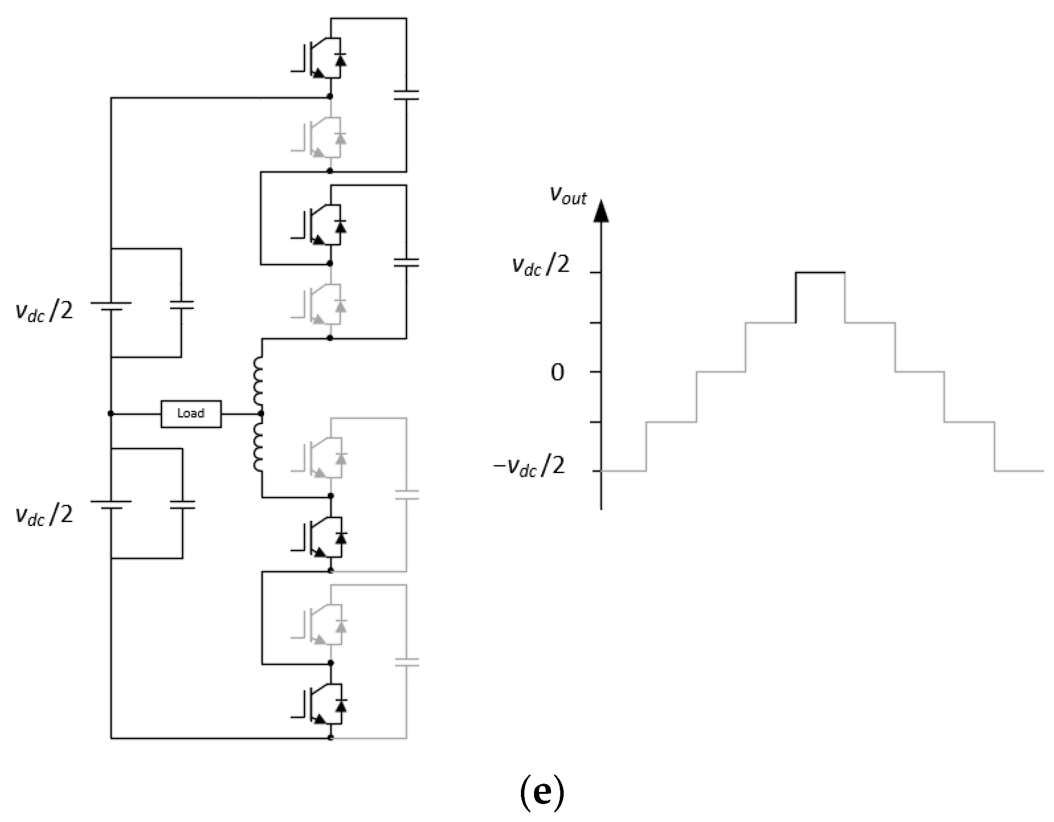
Figure 7, where it is demonstrated an example of the generation of each output level, regarding the switching state of the IGBTs.
For synthesizing the voltage level −
vdc/2, both upper arm submodules must be bypassed, while both lower arm submodules are active. As such, the synthesis of this level does not possess redundancy for the said number of submodules in the converter. For synthesizing the voltage level −
vdc/4, both lower arm submodules must be active and in the upper arm, one submodule must be active while the other is bypassed. This results in two redundant states. For synthesizing the voltage level 0 it is necessary to have the same number of submodules active in the upper and lower arm. As such, there are six redundant states in the generation of this level. For synthesizing the voltage level
vdc/2 both lower arm submodules must be bypassed, while both upper arm submodules are active. As such, there are no redundant states for this level. The output of the converter is summarized in
Table 2.
4. MMC Control Algorithms
This section focuses on the presentation of the techniques used in the control and modulation of the MMC. The control of the power converters is of paramount importance, not only to enable good functioning with the desired outputs synthesis but also to ensure the safety of the converter itself.
4.1. Predictive Control
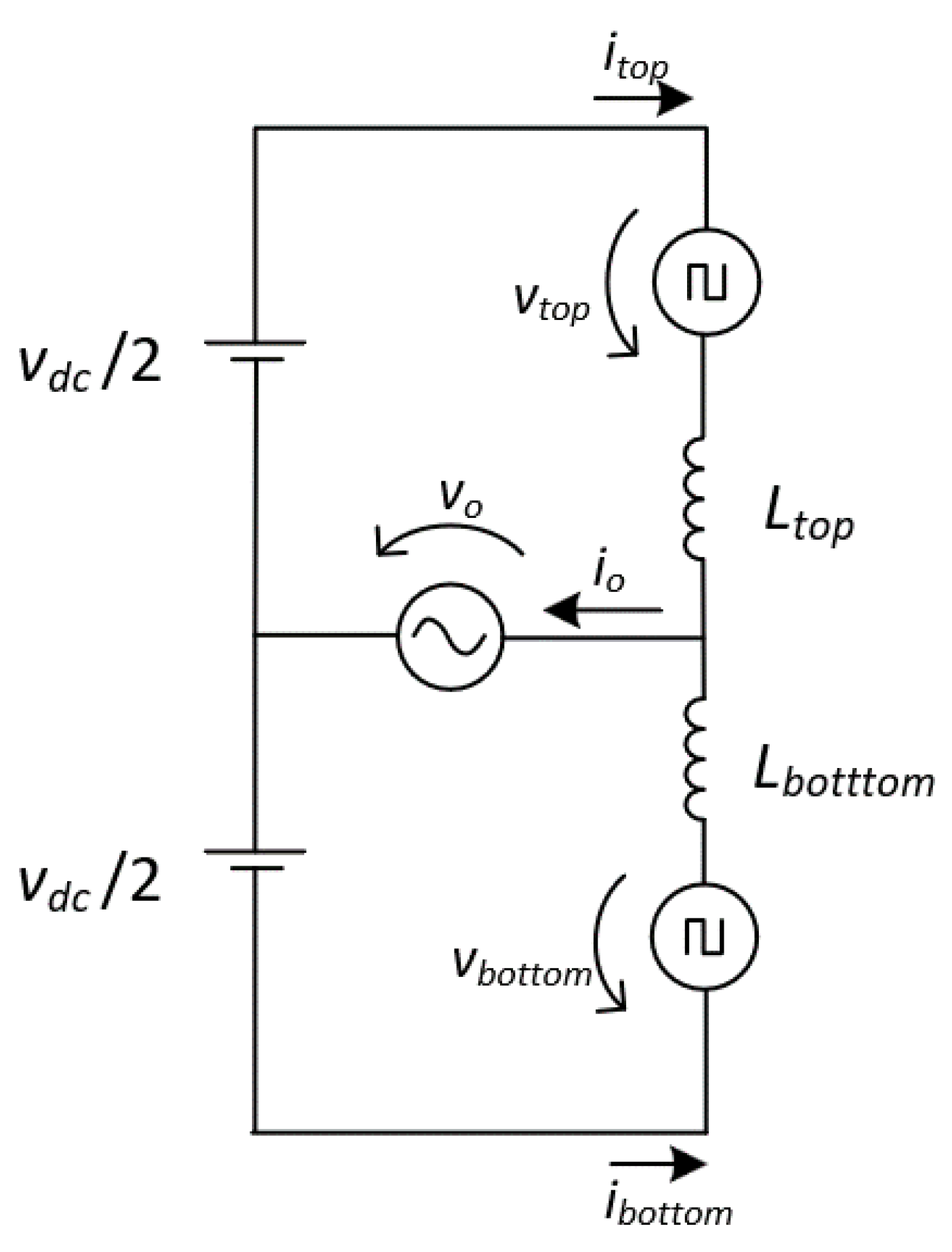
The predictive control calculates the desired control variables based on the electrical model of the converter in the study, without any integral error associated as appears in the PI controller. This type of controller, typically, presents a fast transient response, and small-steady state error, due to its fast dynamic response. To be able to obtain the electrical model of the MMC, its equivalent circuit is presented in
Figure 8.
By applying Kirchhoff’s voltage law on the equivalent circuit, disregarding the internal resistor of the semiconductors, the equations obtained are the following:
The predictive control implemented is a current-based controller, in which the variable in control in each equation is the current flowing in the arm.
The voltage drop in the internal resistors of the inductive filters of the arms of the MMC can be neglected (
and
), due to the low value they have, thus resulting in a simplification of the equations without any significant error associated.
Separating the differential part in the previous equations:
Since the control is performed by a DSP, the equations need to be in discrete time. The discretization of the derivative can be done using the backward Euler method:
where
K indicates the present sample and
K − 1 is the previous sample. By substitution in the previous equations is obtained:
Simplifying the previous equations:
Disregarding the circulating currents, according to the current direction arbitrated in the equivalent circuit, the current in each arm is described by the following equations:
Substituting the previous equations, and introducing
Ts as the sampling period, the final equations are obtained:
The final equations for the reference voltage across each arm in each sampling period are used as the modulator signals for the PWM signals generation, adding the necessary offsets for the capacitor balancing in each submodule.
4.2. Submodule Voltage Balancing
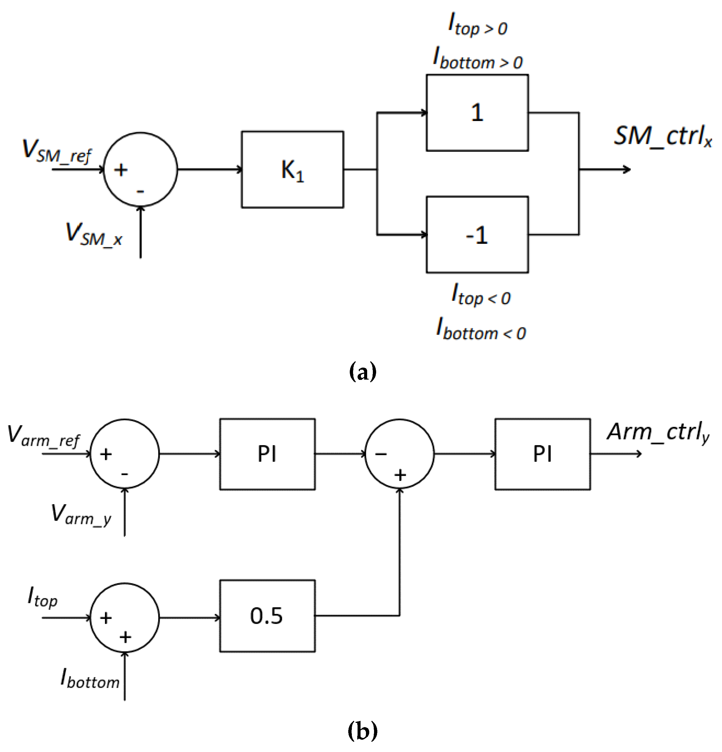
Regarding the control of the voltage balancing across the capacitor of the submodules for a single-phase MMC with only one arm, as is the case of the study, two different steps must be contemplated: the individual voltage control across each submodule and the arm voltage control, both presented in
Figure 9.
The individual voltage control consists of a proportional control of the voltage of each submodule (VSM_x) to follow the arbitrated voltage reference (VSM_ref). Depending on the current direction, the output of the controller is multiplied by one if the current in the arm in which the submodule is integrated is positive, or −1, if the current in the arm is negative. As such, there is a controller unit for every submodule of the MMC, in this case, 4 controllers.
The arm voltage control takes into consideration the currents circulating in the upper arm and in the lower arm of the MMC (Ia_u, Ia_l), which medium value is calculated and summed with the negative output of a PI controller where the arm voltage is the controlled variable. At last, another PI controller is applied to find the control value for each arm. As such, there is a controller unit for every arm of the MMC, in the single-phase case, two controllers.
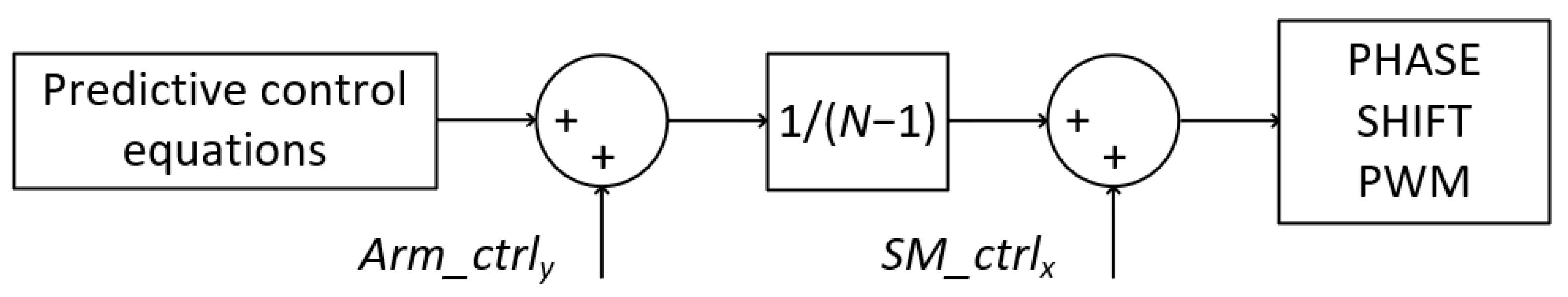
Using predictive control, the final equations are used as input of the controller unit for each submodule, thus generating the reference signals in both approaches as presented in
Figure 10. Then, it is summed the output of the arm voltage controllers (
Arm_ctrly), followed by a gain of 1/(
N − 1), where
N relates to the number of submodules in each arm. Finally, the output of the controller of the voltage of each submodule (
SM_ctrlx) is summed to the reference signal, having created the modulators for the phase shift PWM.
4.3. Phase Shift Carrier Modulation
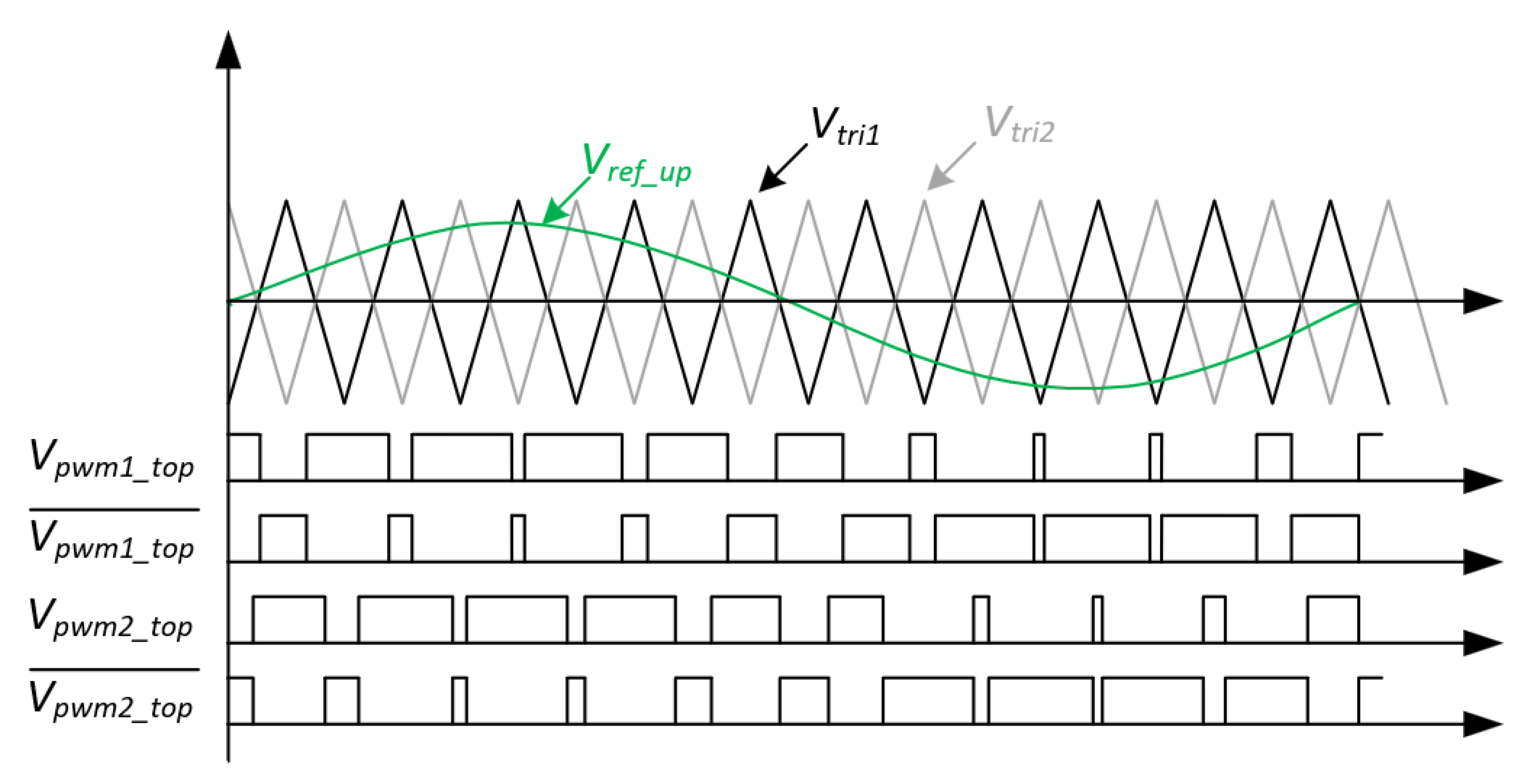
In phase-shit carrier PWM, all the triangular carrier signals have the same frequency, peak-to-peak amplitude, and offset value, but the phase disposition of the triangular carriers varies. The carrier signals are disposed of with a 2π/
N phase shift between them, where
N represents the number of submodules in each arm of the MMC.
Figure 11, illustrates the referred modulation technique for an arm of an MMC composed of two submodules. For a better understanding of the modulation technique through visualization of the waveforms of the carrier signals and the modulator signals, the modulator signals were disposed of 50 Hz frequency and the carrier signals with 500 Hz frequency. In a practical implementation, typically, this frequency would be higher, in the order of a few kHz to tens of kHz. In this figure,
Vref_up corresponds to the reference of the up arm, while
Vtri1 and
Vtri2 correspond to the reference of the necessary two carriers with a phase disposition of 180 degrees. The variables
Vpwm1_top,
Vpwm2_top, as well as the corresponding complementary values, corresponds to the gate pulse-pattern of the IGBTs that constitute the MMC with two submodules.
5. MMC Computational Simulations
Recurring to computational simulations, it is possible to study and develop a realistic model of the power converter to implement, as well as to allow a fine-tuning of the control algorithms. As such, a simulation model of the MMC was developed, using the PSIM software, to study the behavior of the MMC in a real scale of operation, and assess the dynamic response of the converter to load variations on the electrical power grid side. Such dynamic response was studied for both gradual and instantaneous transients.
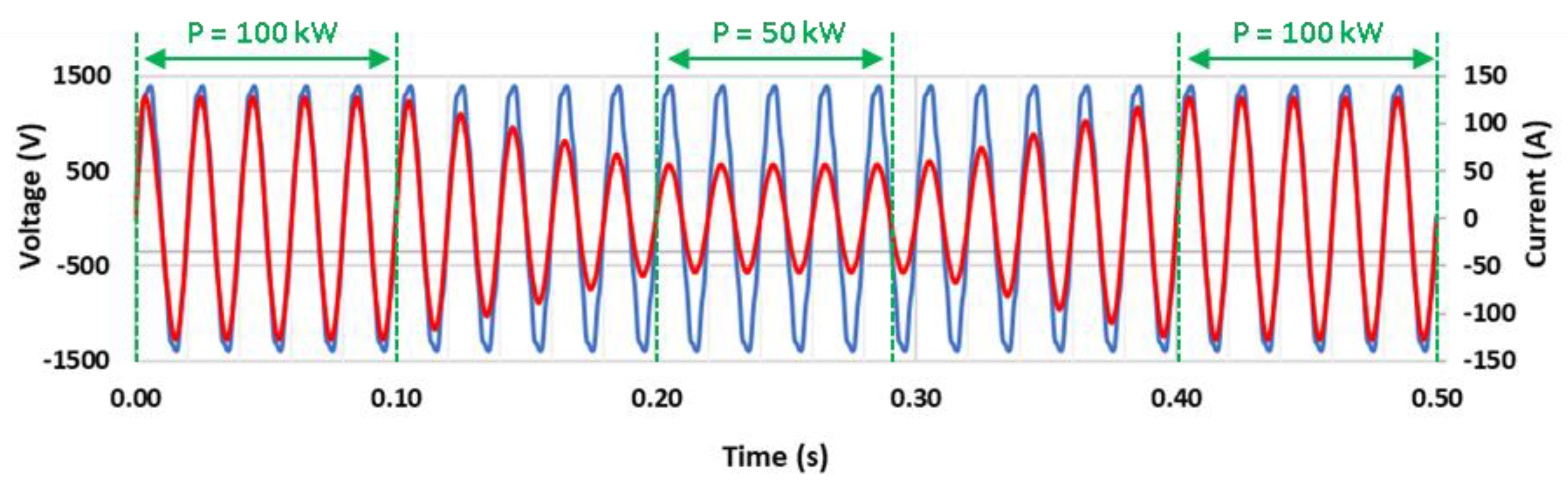
In the first approach, the gradual transients were studied, with a decreasing variation from 100 kW to 50 kW operating power over 5 grid cycles, as well as the same increasing variation. Such results are presented in
Figure 12. The voltage from the electrical power grid does not suffer any sudden variation, while the current gradually decreases, stabilizes, and increases, according to the operating power. In both cases, it is possible to visualize a near sinusoidal current produced by the static converter, while the power grid voltage presents harmonic distortion of nearly 4%, inherent to the distribution power grid.
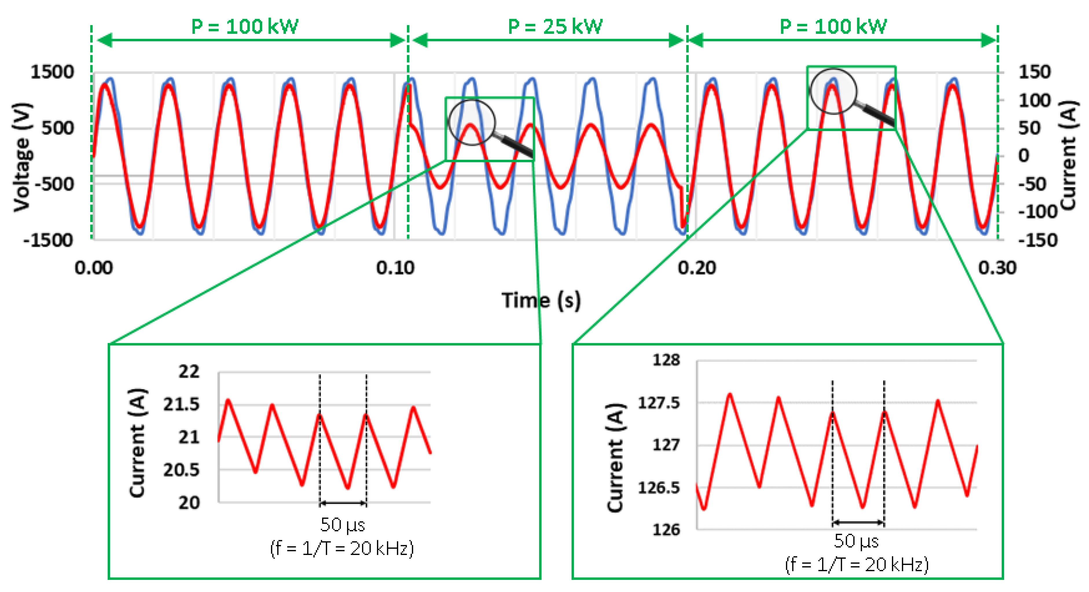
In a second approach, the transient response to instantaneous variations of the operation power was studied, as presented in
Figure 13. First, the power abruptly decreases from 100 kW to 25 kW, and later, after 4 and a half cycles of the power grid voltage, it suddenly increases again to 100 kW. It is possible to verify the good dynamic response of the railway static converter, which produces an almost sinusoidal current with a value according to the reference, and no disturbances are registered during the abrupt variations of the operating power.
In addition to the dynamic response assessment, the total harmonic distortion (THD) of the current was registered considering different power operation values, aiming to understand the influence of the power value in the distortion of the current waveform. As shown in
Figure 13, the raise of the rated power increases the current value and, as the current ripple does not change, since the switching frequency remains constant (20 kHz), the THD value of the current decreases. As such, the higher the rated power, the lower the THD value of the current, as can be observed in
Table 3.
6. MMC Prototype Implementation
This section presents the development and implementation of the MMC prototype, with two submodules in each arm, which is used to interface with the electrical power grid. The developed hardware was designed to be as modular as possible, as well as portable to other projects in the laboratory. This means that each submodule is implemented in a single PCB, a generic half-bridge converter, and the control part possesses separate boards as well. Furthermore, to improve scalability and create a system with higher modularity, the driver circuit was developed in a separate board plugged into the submodule board, as can be observed in
Figure 14.
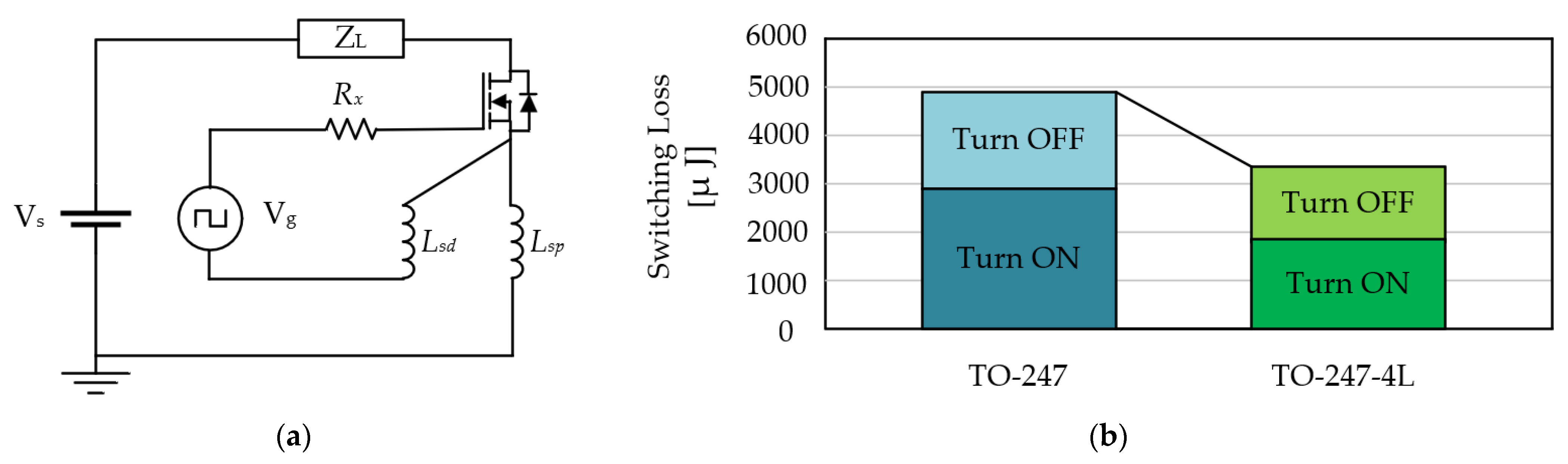
Each submodule is equipped with a voltage sensor for monitoring and control of the voltages across the capacitors, to keep the system balanced. Furthermore, a submodule in each arm is equipped with a current sensor that monitors the current flowing in the arm, both for protection, and to serve as input to the predictive control. The selection of components that integrate the driver and submodule boards were carefully selected to reduce the parasitic effects to the maximum, as well as to ensure operation at the best possible conditions. As such, regarding the selection of the semiconductors, the goal was to take advantage of the kelvin source configuration, which consists of the use of two separate source pins, responsible for the driver reference and the power signal, respectively, present in the TO247-4L case.
Figure 15a presents the switching model of the TO-247-4L encapsulation, with detail on the source connections, while
Figure 15b demonstrates a switching loss graphic comparison of the TO-247 and TO-247-4L encapsulation [
35]. This results in a minimization of parasitic effects operating at high current and high switching frequencies, resulting in lower losses. As such, it was used the IGBT IKZA50N65RH5 manufactured by Infineon Technologies.
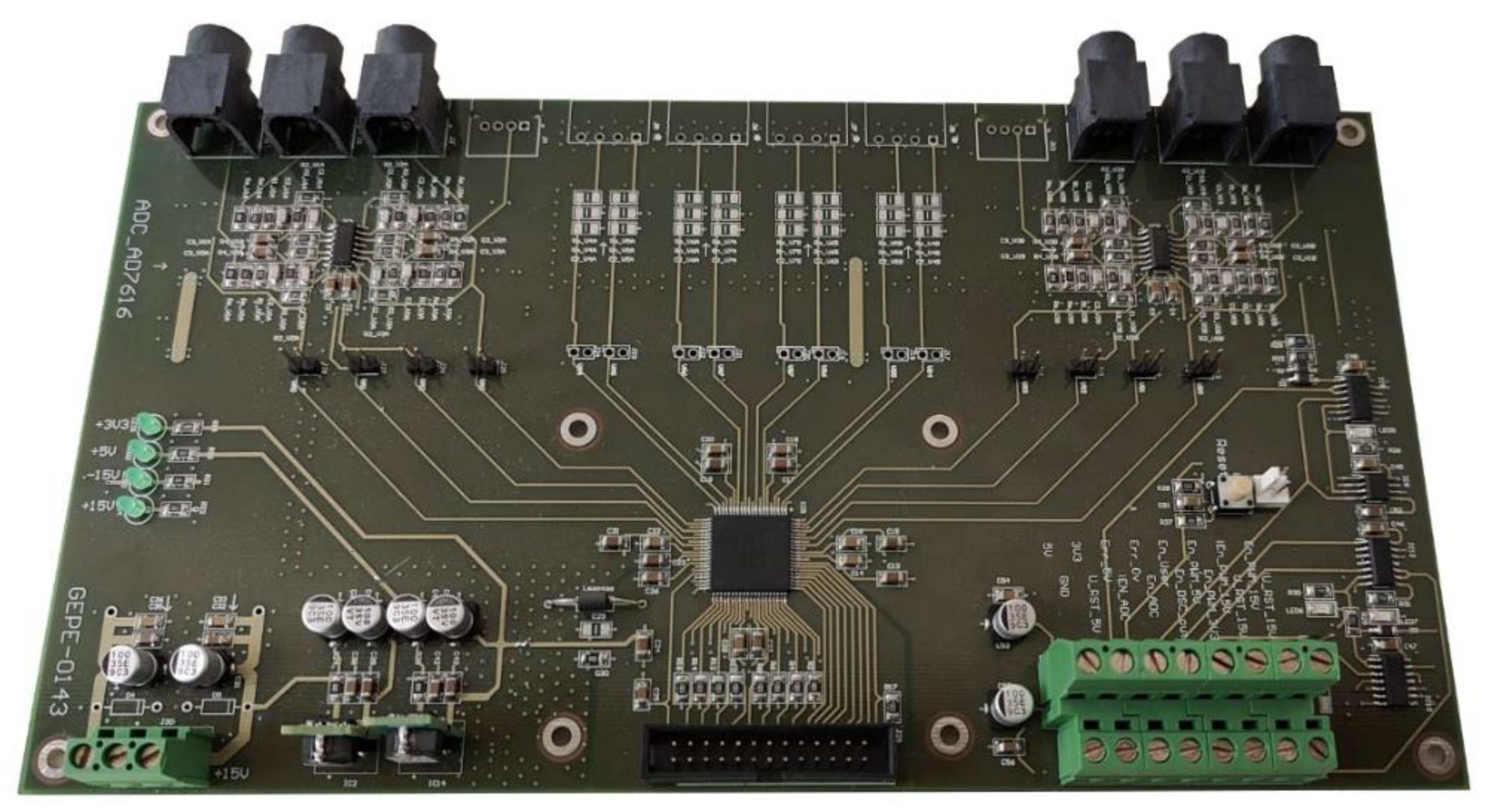
Regarding the acquisition of signals, a PCB was developed containing an external ADC with 16 channels and 16-bits, which possesses signal conditioning with a second-order low pass filter, and hardware protection via window comparator and error memorization, which proved to be a powerful tool, both for the high resolution of data acquisition and for the safe operation of the converter. The developed board is presented in
Figure 16.
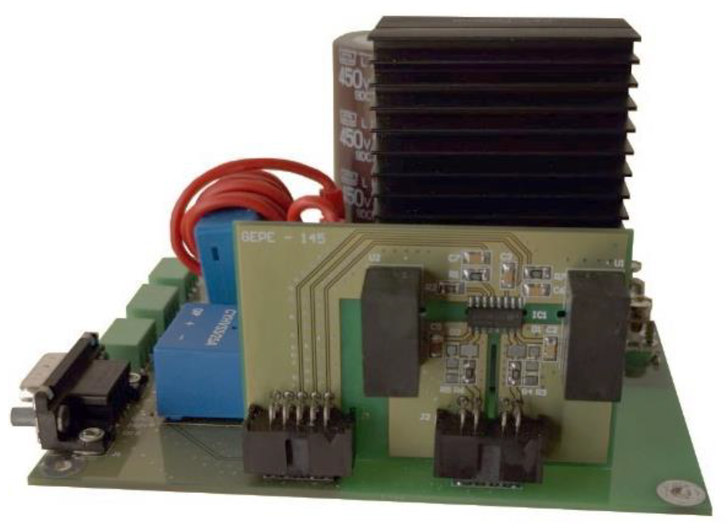
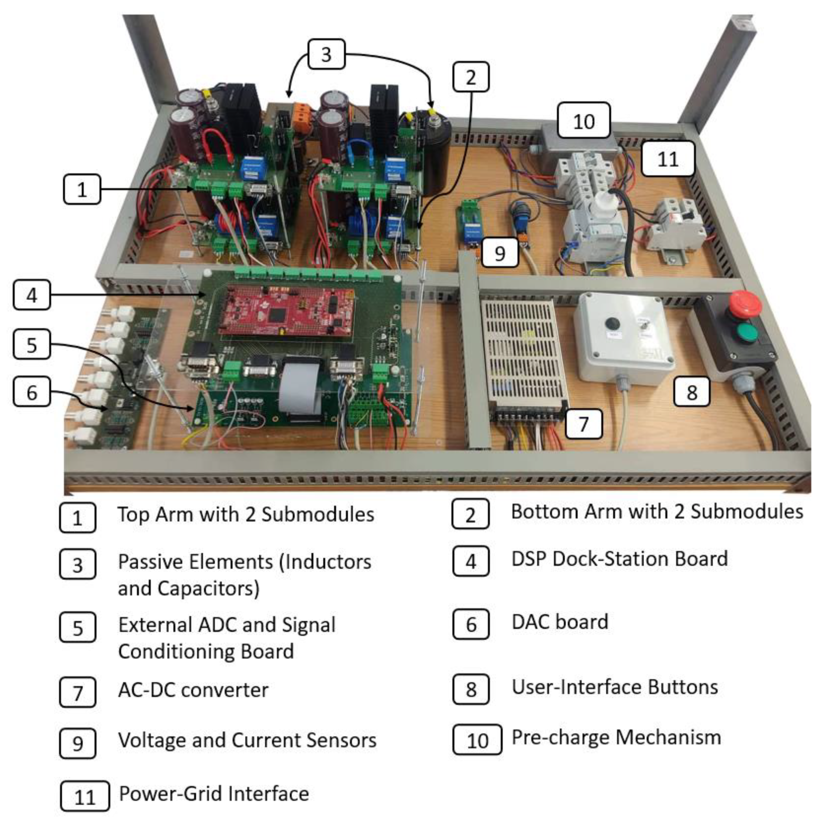
According to the signals that are necessary to be acquired, the signals conditioning and hardware protection were dimensioned for five voltage sensors and three current sensors. Once the board was assembled, it was developed software for the parallel communication between the external ADC and the DSP TMS28379D, from Texas Instruments, and the final prototype was implemented, as shown in
Figure 17.
The power stage of the final prototype includes four submodules and respective drivers, two DC-link capacitors in parallel with the input power supplies, two pre-charge resistors with bypass switches, a circuit breaker, and connectors for the loads or a transformer. It is important to mention that a physical protection mechanism, human-activated was implemented to shut down the power supplies and the transformer recurring to an interlock stop button. Once this button is pressed, for the power supplies to be turned back on, first it is necessary to unlock the stop button, and then press the start button. Furthermore, whenever the power supplies are connected, a red light is turned on and remains on until the power is disconnected.
Regarding the connection of the submodules to each other, the power signals to the primary drivers are shared among the four submodules to avoid the creation of ground loops since they all share the same potential without closing the loop. This was a critical part of the design of the system since its unification required many connections between all the boards, with a common potential being shared in all, the ground. To minimize the ground loops, the ground signal was distributed from the DSP dock station board to the others.
The control stage of the final prototype includes the DSP dock station board, connected through a flat cable to the external ADC board. The supply of the control stage is ensured by an AC-DC converter manufactured by Traco Power, which possesses the necessary outputs that the control system requires: 15 V, −15 V, and 5 V. To facilitate the hardware debugging and the visualization of the control signals, a DAC board utility developed in the laboratory was used.
The prototype is equipped with gutters all around to facilitate the connections, as well as provide an aesthetic improvement of the final visualization. The layout of the prototype consisted of a visible separation of the control and power stages allowing better debugging in terms of hardware and troubleshooting. Furthermore, the cables from the same circuits were twisted in pairs to reduce electromagnetic radiation from one another, as well as mitigate the crosstalk with other cables.
7. MMC Experimental Validation
In this chapter, the experimental results that allow the validation of the proposed topology, an MMC with two submodules in each arm in a half-bridge topology, are presented. To fully validate the MMC, three different results are presented: load steady-state regime, load transient-state regime, and electrical power grid interface.
7.1. Steady-State Operation
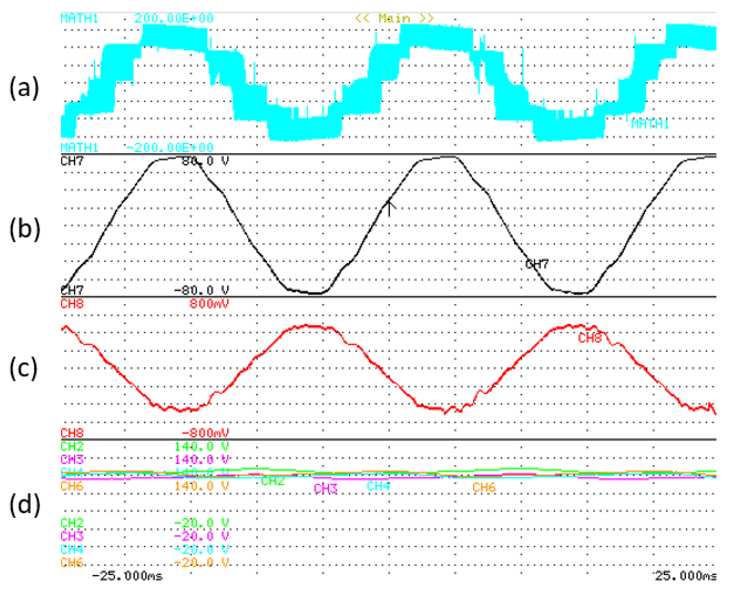
The results presented in
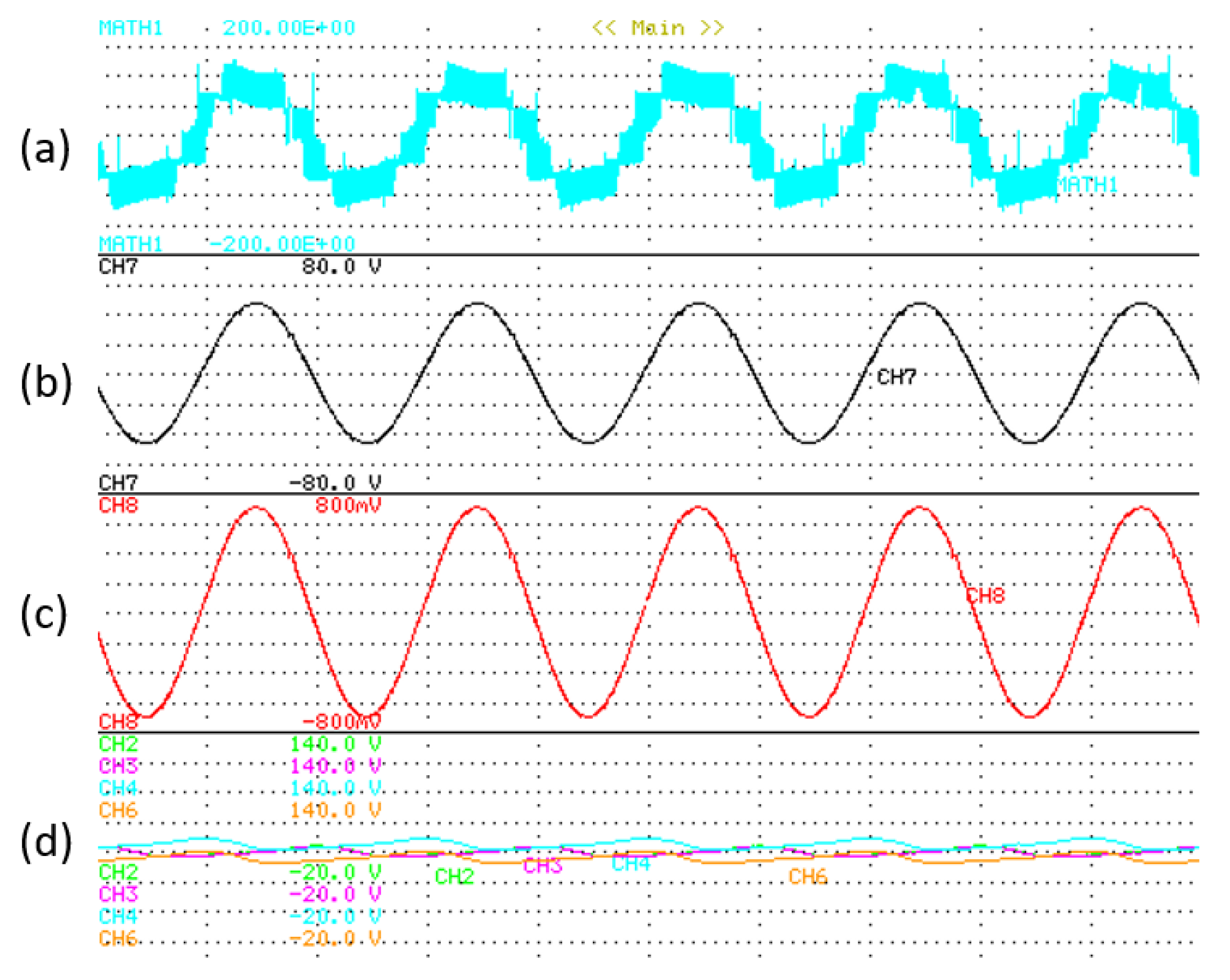
Figure 18 were obtained using a 6.5 Ω resistor as load, a voltage of 140 V in the split DC-link, and a reference signal of 5 A RMS, 50 Hz, as presented in
Table 4.
The experimental results of the MMC operation in the closed-loop current control with submodule voltage balancing are presented, including the voltage levels measured between the inductive filters in (a) the output voltage of the converter in (b) with a 20 V/div. the load current in (c) with a 2 A/div, and the voltage of the four submodules in (d) with a 20 V/div.
As the load is resistive, the output voltage of the MMC is the product of the current with the resistor value, resulting in a 32.5 V RMS voltage signal. The output current follows the reference stipulated and the voltage across all the submodules remains constant with a medium value of 60 V.
7.2. Transient-State Response
The results in the transient-state were obtained under similar circumstances as the previous ones, changing, however, the control to the voltage variable, to create a transient event in the current upon a load change, and access the power converter behavior. The reference given to the voltage was a 50 V peak to obtain similar results with the previous upon the occurrence of the transient event. The parameters are presented in
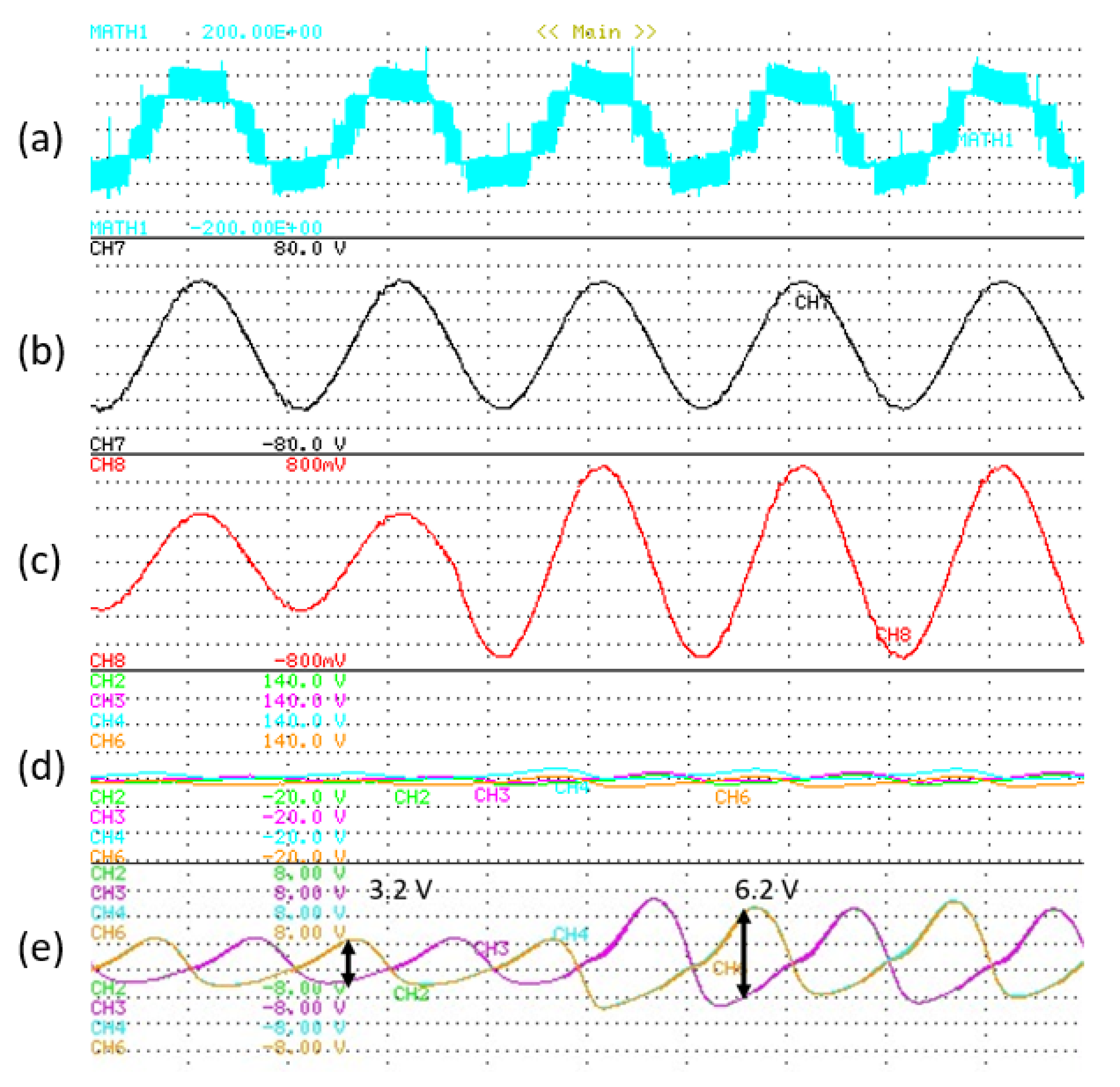
Table 5, and the experimental results are shown in
Figure 19.
From the output of the converter perspective, the output voltage follows the reference at all times, including in the current transitory for double the previous value in the load change, as intended. Regarding the balancing of the submodules, it is possible to observe that the medium value of the voltage across the four submodules is approximately 60 V.
The results in
Figure 19e were acquired by changing the submodule voltage scale on the oscilloscope to 2 V/div and the coupling to DC, thus disregarding the medium value, to take a closer look at the detail of the ripple voltage across the submodules. As foreseen, the ripple increases with the power at stake in the MMC. Using approximations in the following values, for a 90 W output, the ripple is about 3.2 V, while for 180 W, the ripple is roughly 6.2 V, disregarding the first transitory.
The results obtained allowed the validation of the submodule voltage balancing control, enabling the possibility to power the MMC using only power supplies in the DC-link of the converter.
7.3. Electrical Power Grid Interface
To interface with the electrical power grid, the MMC was through a 230 V//50 V transformer. The split DC-link of the power converter was powered with 240 V, i.e., 120 V in each power supply. As the voltage across the capacitors of the submodules possesses a significant capacitance, a pre-charge was effectuated using a 100 Ω resistor in series with both arms presented in the prototype. In the selected MMC topology, the pre-charge circuit can only charge the capacitors to half the voltage nominal voltage, 60 V in this case. Regarding the reference value for the output of the MMC, the results presented were acquired for a 300 W output reference, as presented in
Table 6. The output voltage of the converter is imposed by the grid, only varying the current output of the converter.
In
Figure 20, the results for a 300 W power reference in interface with the electrical power grid are presented. The results contain the output voltage levels of the MMC measured across the inductive filters in (a), the output voltage of the converter in (b) with a 20 V/div, the output current of the converter in (c) with a 2 A/div and the voltage across the submodules with a 20 V/div.
As can be observed, the output voltage of the converter is slightly above the 50 V RMS, which is necessary for the power converter to inject power into the electrical grid. As the power converter is indeed injecting power into the electrical grid, the current is in phase opposition with the output voltage, possessing however slight distortion in its waveshape. Regarding the voltage across the submodules, using 120 V in each power supply of the DC-link, the medium voltage of the arm voltage settled at 200 V, thus selecting 100 V for reference for each submodule, and it can be observed that the balancing is successfully obtained. Recurring to a digital wattmeter, the measured power output of the MMC was 302 W.
Regarding the operation of all power converters, the temperature of the semiconductors is of major concern since the heat degrades the conduction characteristics, which results in more power losses in the circuit. This leads to a cycle of loss in efficiency, and, as such, the temperature of the IGBTs and the corresponding heat sink was monitored at all stages, recurring to a thermal camera. After 20 min of operation with an output power of 302 W, with a room temperature of 26 °C, the temperature in the heatsinks of the IGBTs of all submodules was measured, having verified a 33 °C temperature in all measurements, meaning an equal raise of 7 °C in all submodules IGBTs. This test also allowed the verification that after 20 min of operation, the behavior of the power converter remained unshaken.
The efficiency of the converter was verified through measurements of the input and output power. The maximum output power measured was 302 W, operating with an efficiency of 93%.
8. Conclusions
This paper presents the development of a reduced-scale single-phase modular multilevel converter (MMC), as well as its experimental validation. The distinct voltage and current control algorithms, as well as the modulation technique for the MMC, are described in detail and the control equations are obtained aiming for a digital control implementation. The details of the developed laboratory prototype are presented, where all the distinct parts are described. The experimental validation, performed both in a transient-state and steady-state, was accomplished, presenting satisfactory results in different stages of operation, and with different types of control, both in voltage and in current. The experimental validation was performed for two different scenarios: considering a resistive load (with the MMC operation as a voltage-source converter with voltage feedback control), and considering the interface with the electrical power grid (with the MMC operation as a voltage-source converter with current feedback control). Regarding the voltage across all the submodules, it was verified that due to voltage drops across the MMC, the medium value of the voltage was slightly inferior to the theoretical value, which was considered in the control of the MMC, most specifically, in the submodule voltage control.
Finally, considering the operation interfacing with the electrical power grid, it was verified that the MMC injects power into the electrical power grid with a low distortion in the current signal, and accordingly to the power reference provided by the controller. Regarding the efficiency of the reduced-scale prototype, it was measured at a maximum operation power of 302 W, resulting in an efficiency of 93%. To further assess the dynamic behavior of the railway static inverter, as well as the THD in full-scale operation, a simulation model was developed which enabled the possibility to study the fast response of the power converter in both gradual and pulse current alterations, as well as the decrease of the THD with the increase of the rated power. As shown, it was analyzed the voltage and current dynamic response considering a gradual power variation from 100 kW to 50 kW, and vice-versa, as well as the dynamic response considering instantaneous transients from 100 kW to 25 kW, and 25 kW back to 100 kW, showing, in both cases, the good response of the proposed control for this type of application.


