Communication

Fast Wide-Band RCS Analysis of the Coated Target Based on PBR Using EFIE-PMCHWT and the Chebyshev Approximation Technique

National Key Laboratory of Science and Technology on Antennas and Microwaves, Xidian University, Xi’an 710071, China
*
Author to whom correspondence should be addressed.
Electronics 2023, 12(4), 923; https://doi.org/10.3390/electronics12040923
Submission received: 30 November 2022 / Revised: 20 January 2023 / Accepted: 10 February 2023 / Published: 12 February 2023
(This article belongs to the Special Issue Wideband and Multiband Antennas for Wireless Applications)

Abstract

:
The Chebyshev approximation technique (CAT) combined with the MoM based on the electric-field integral equation (EFIE) and the Poggio–Miller–Chang–Harrington–Wu–Tsai (PMCHWT) integral equation is proposed to efficiently calculate the wide-band radar cross-section (RCS) based on passive bistatic radars (PBR). The EFIE-PMCHWT equations can be used to analyze the electromagnetic scattering of coated targets. The combination with CAT only requires computing the electric and magnetic currents at a few Chebyshev frequency points, which can be employed to obtain the electric and magnetic currents over the entire frequency band. In this study, the RCS values of a coated target calculated by the hybrid EFIE-PMCHWT-CAT based on passive bistatic radar (PBR) were found to be consistent with that calculated by the MoM based on the EFIE-PMCHWT. The validity of the hybrid method is verified by several numerical examples. Compared with the conventional MoM method, the hybrid method can greatly improve the efficiency for electromagnetic scattering problems over a wide frequency band.

1. Introduction

In recent decades, passive bistatic radar (PBR) has been extensively studied for different applications with the non-cooperative illuminator because it has many advantages, such as good anti-comprehensive electronic interference, low cost, and so on. The research of PBR based on base station, FM radio [1], and satellite [2] has made remarkable achievements, and the prediction of the RCS of passive bistatic radars (PBR) [3,4] based on a non-cooperative illuminator has been proposed. One of the main issues based on the PBR is to predict the RCS of the coated target.
The coated target includes the dielectric/metallic composite structures, which have been widely used in many engineering applications [5,6]. Various coatings are usually mounted on stealth military equipment, microwave planar circuits, radomes, and wireless communication facilities [7]. The application of the method of moments (MoM) [8,9,10], which is a full-wave method, has reached maturity. The MoM has been widely adopted for calculating the RCS of perfect electric conductors. For the dielectric material problem, two methods based on the MoM have been proposed to solve the electromagnetic scattering problem, including the PMCHWT equation [11] and the volume integral equation (VIE) [12]. Meanwhile, many methods are proposed to analyze the EM scattering problems of coated target, such as the thin dielectric sheet (TDS) [13] method, shooting and bouncing ray (SBR) [14], impedance boundary condition (IBC) [15], and so on. In general, for the coated targets, the EFIE-PMCHWT integer equation [16,17,18] based on the MoM proposed by Sadasiva M. Rao et al. is more popular than others since the EFIE-PMCHWT integral equations can deal with the EM scattering problems of any arbitrary shaped conducting bodies coated with an arbitrary thickness. Compared with the VIE, the EFIE-PMCHWT integral equations only require meshing the surfaces of dielectric and metallic parts by using the triangles, which causes the number of unknowns of EFIE-PMCHWT to be much fewer than that of VIE. However, when obtaining the broadband radar cross-section, the traditional EFIE-PMCHWT integral equations need to calculate the currents for each frequency point, which makes it difficult to quickly calculate the electromagnetic scattering characteristics.
To overcome this problem, some theories are proposed. The first method is employing parallel computing [19,20], which means more requirements of memory and CPU. On the one hand, parallel computing extremely relieves the storage capacity of the hardware. On the other hand, the computing task is divided into multiple copies and executed on tens of thousands of CPUs at the same time, which can reduce the calculation time effectively. Other approaches involve employing a fast sweeping frequency algorithm, such as the asymptotic waveform evaluation (AWE) technique [21] and the Cauchy method [22]. In AWE, around the center frequency, the currents will be expanded in the Taylor series to improve the accuracy. However, AWE needs to calculate the higher derivative of the impedance matrix and incentive vector, which leads to the CPU time and memory requirements greatly increasing. Among these techniques, the CAT is more popular than others. Firstly, CAT [23,24] is easily combined with another traditional method, such as the finite element method (FEM) [25], finite element-boundary integral method (FE-BI) [26], fast multipole method (FMM) [27,28], FE-BI-multilevel fast multipole algorithm (FE-BI-MLFMA) [29], MoM-physical optics (MoM-PO) [30], and so on. Secondly, compared with AWE, for a desired frequency, by using the Chebyshev series to calculate the currents, there is no need to compute the high derivatives, which reduces the computational complexity.
In this paper, a novel hybrid EFIE-PMCHWT-CAT algorithm is proposed for fast wide-band RCS computation of arbitrarily shaped 3D-coated targets based on the PBR. In the proposed hybrid method, the currents at any frequency point of the whole broadband can be obtained by calculating the currents at the Chebyshev frequency sampling node since there is no need to calculate the RCS of every sweeping point, which avoids the problem of wasting time. The result is consistent with that of EFIE-PMCHWT based on the MoM.
The remainder of this paper is organized as follows. The EFIE-PMCHWT formulation of arbitrarily shaped 3D-coated targets based on the PBR is established in Section 2. The formulation of the CAT application to EFIE-PMCHWT is explicitly derived in Section 3. Finally, three examples are presented in Section 4 to verify the accuracy and efficiency of the hybrid EFIE-PMCHWT-CAT algorithm, and the conclusion of this work is drawn in Section 5.

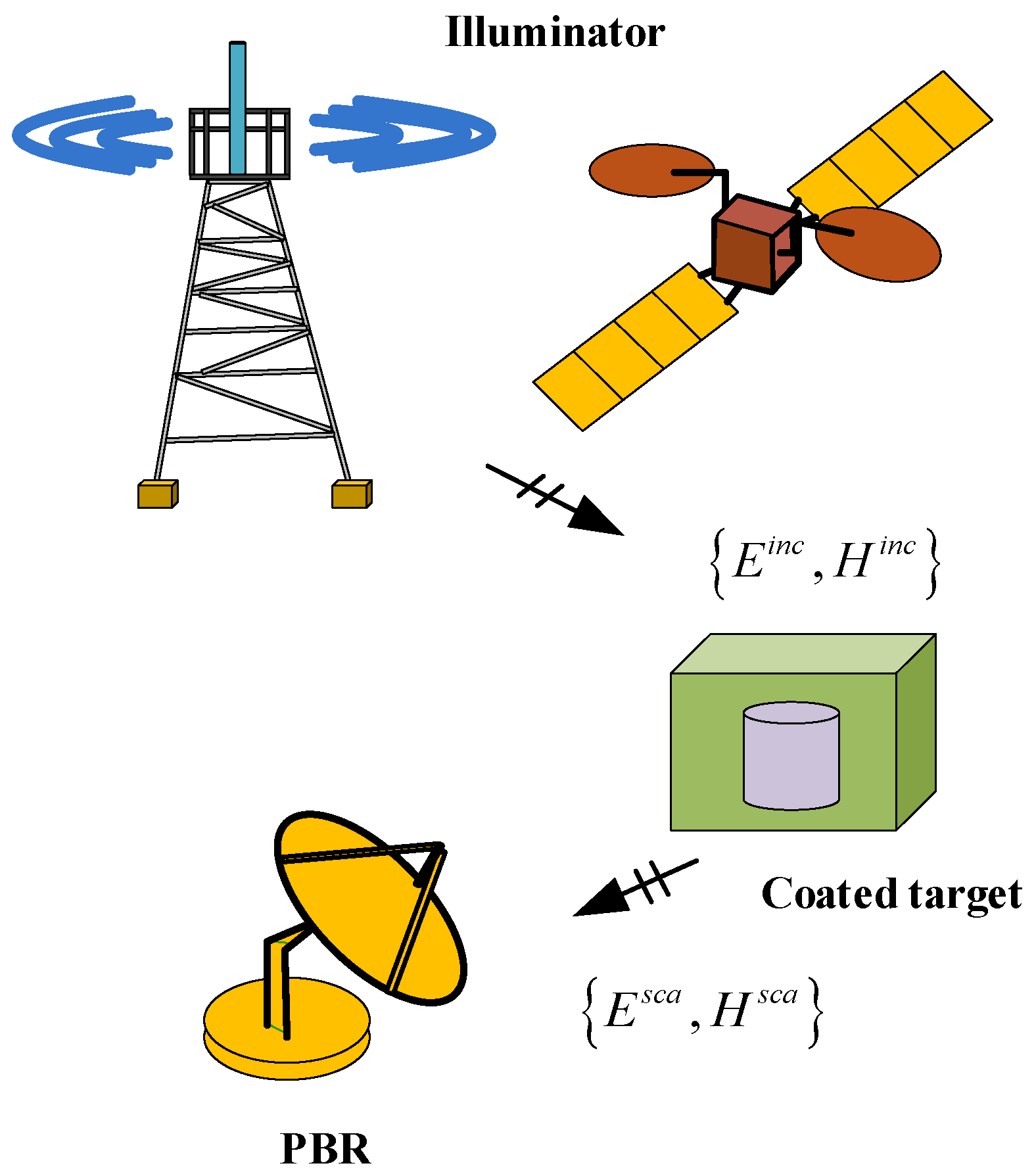
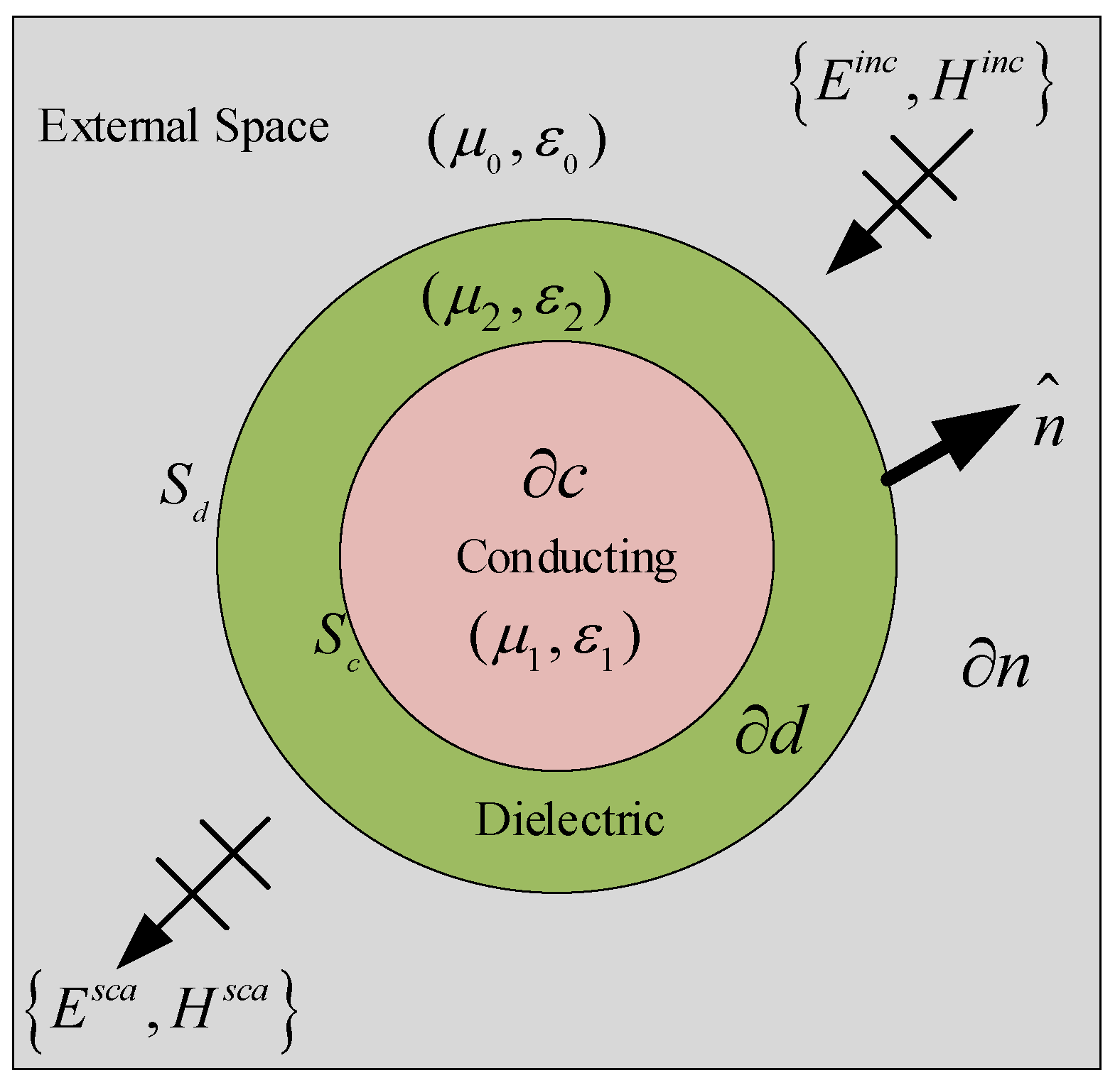
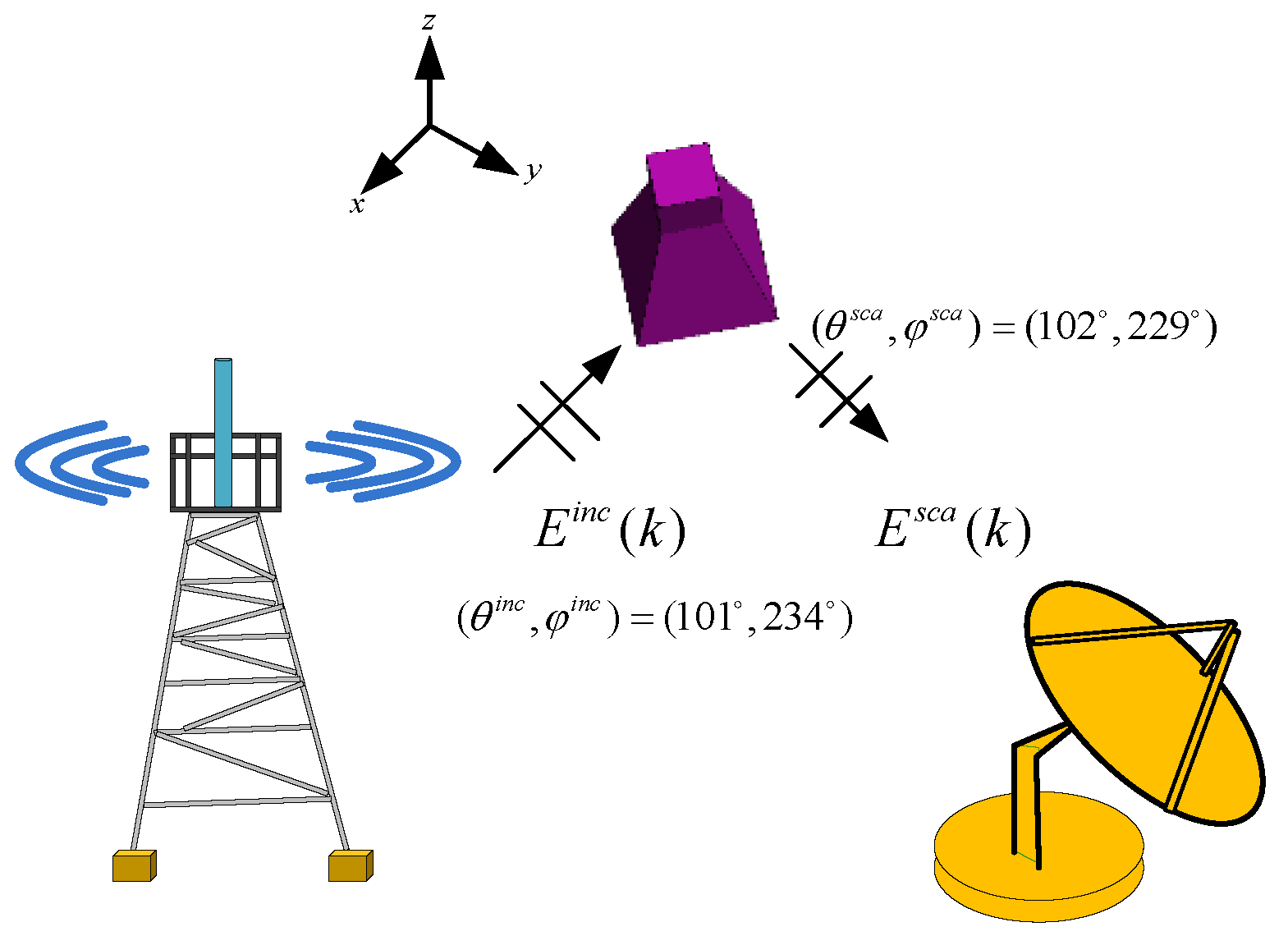
2. Wide-Band EM Scattering of Coated Target Based on Passive Bistatic Radar

Consider the wide-band EM scattering problem of coated target based on the passive bistatic radar for a desired frequency band [ f a , f b ] in Figure 1. The wavenumber will vary from k a to k b with frequency f . The target is illuminated by the non-cooperative illuminator and the satellite and base station are chosen as non-cooperative illuminators. { E i n c , H i n c } and { E s c a , H s c a } represent the incident wave and scattering wave, respectively.
Figure 2 shows an example of a dielectric-coated PEC embedded in a background medium with parameters ( μ 0 , ε 0 ) . The perfect electrical conductor is immersed in a dielectric coating with parameters ( μ 2 ,   ε 2 ) . Let c , d , and n represent the perfect electric conductor, dielectric region, and background medium region. The surface of dielectric and perfect electric conductor is denoted by S d and S c , and ( μ 1 , ε 1 ) represents the electromagnetic parameters of c . The target is excited by an incident wave that comes from a non-cooperative illuminator. n ^ is the outward normal unit vector. By introducing the equivalent surface principles, two equivalent problems are formulated.
The equivalent external problem is shown in Figure 3a. The electric field and magnetic field of the region d are assumed to be zero, and the permittivity and permeability of the region d are the same as that of the region n . Equivalent electric current J d and magnetic current M d are generated outside surface S d . Two currents are defined as Equation (1).
J d = n ^ × H s c a M d = E s c a × n ^
With the boundary conditions, the following equations can be obtained:
[ E d e ( J d ; k ) + E d e ( M d ; k ) + E i n c ] tan = 0
[ H d e ( J d ; k ) + H d e ( M d ; k ) + H i n c ] tan = 0
Figure 3b shows the equivalent interior situation. The electric field and magnetic field of n are assumed to be zero, and the permittivity and permeability of n are the same as that of the region d . Outside the surface S d , currents are noted as J d and M d . The outside surface of the conducting electric current J c is introduced. With the boundary conditions, the following equations can be obtained:
[ E c i ( J c ; k ) + E d i ( J d ; k ) + E d i ( M d ; k ) ] tan = 0
[ H c i ( J c ; k ) + H d i ( J d ; k ) + H d i ( M d ; k ) ] tan = 0
[ E c i ( J c ; k ) + E d i ( J d ; k ) + E d i ( M d ; k ) ] tan = 0
In (2)–(6), the superscript e and i represent the field in the equivalent external problem and interior external problem. The subscript d and c mean the field motivated by the currents of the dielectric and conductor. [ · ] tan represents the tangential component. k represents the wavenumber. Combining Equations (2)–(6), we can obtain a set of equations:
n ^ × [ L 1 ( J d ) + L k ( J d ) + K 1 ( M d ) + K k ( M d ) - L k ( J c ) ] = n ^ × E i n c
n ^ × [ K 1 ( J d ) K k ( J d ) + 1 η 1 2 L 1 ( M d ) + 1 η 2 2 L k ( M d ) + K k ( J c ) ] = n ^ × H i n c
n ^ × [ L k ( J d ) + K k ( M d ) - L k ( J c ) ] = 0
The operators L i ( X ) and K i ( X ) are written as:
L i ( X ) = j k i η i ( 1 + k i 2 ) G i ( r , r ; k i ) × X ( r ) d s
K i ( X ) = X ( r ) × G i ( r , r ; k i ) d s
where G i and k i are noted as
G ( r , r ; k i ) = e j k i | r r | 4 π | r r |
k 1 = 2 π f a / c k i = 2 π f ε 2 ε 0 μ 0
By using the triangle to mesh the surface of the perfect electrical conductor and dielectric, the electric currents J d , J c and the magnetic current M d may be approximated as:
J d = n = 1 N d α n f n
M d = n = 1 N d β n f n
J c = n = 1 N c γ n f n
f n represents the RWG basis functions. α n , β n , and γ n are unknown coefficients. The parameters N d and N c are the number of RWG basis functions on the dielectric surface and metallic surface, respectively. The RWG basis function is defined on a pair of triangles. Therefore, to determine the values of N d and N c , we need to search the number of common edges according to the coordinates of the three vertexes of each triangle.
To convert Equations (7)–(9) into a matrix equation, we test Equations (7)–(9) with RWG basis functions. The matrix is noted as:
[ Z J d J d ( k )     Z M d J d ( k )       Z J c J d ( k ) Z J d M d ( k ) Z M d M d ( k ) Z J c M d ( k ) Z J d J c ( k )     Z M d J c ( k )       Z J c J c ( k ) ] [ I J ( k ) I M ( k ) I C ( k ) ] = [ V J ( k ) V M ( k ) 0 ]
Z is a ( 2 N d + N c ) × ( 2 N d + N c ) matrix; V includes the information of incident wave; I denotes unknown current densities.

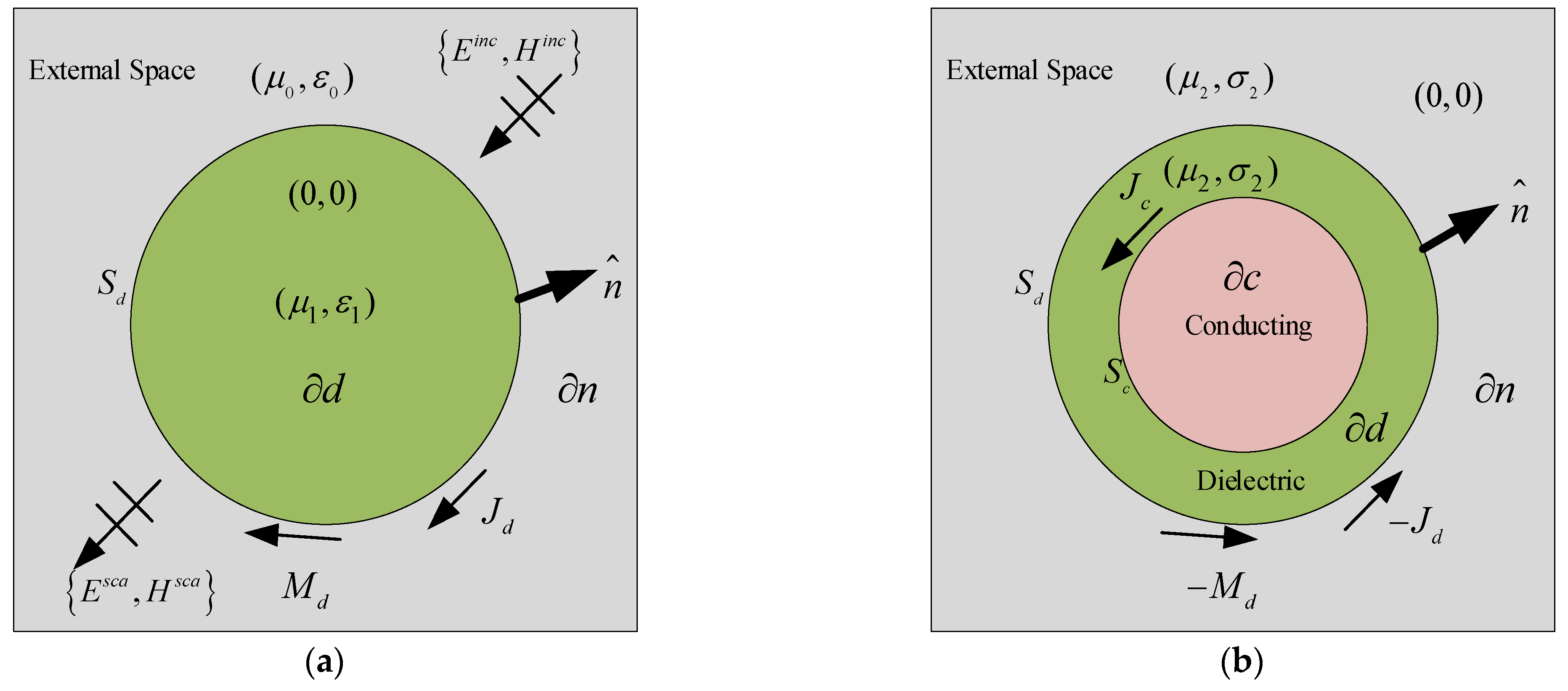
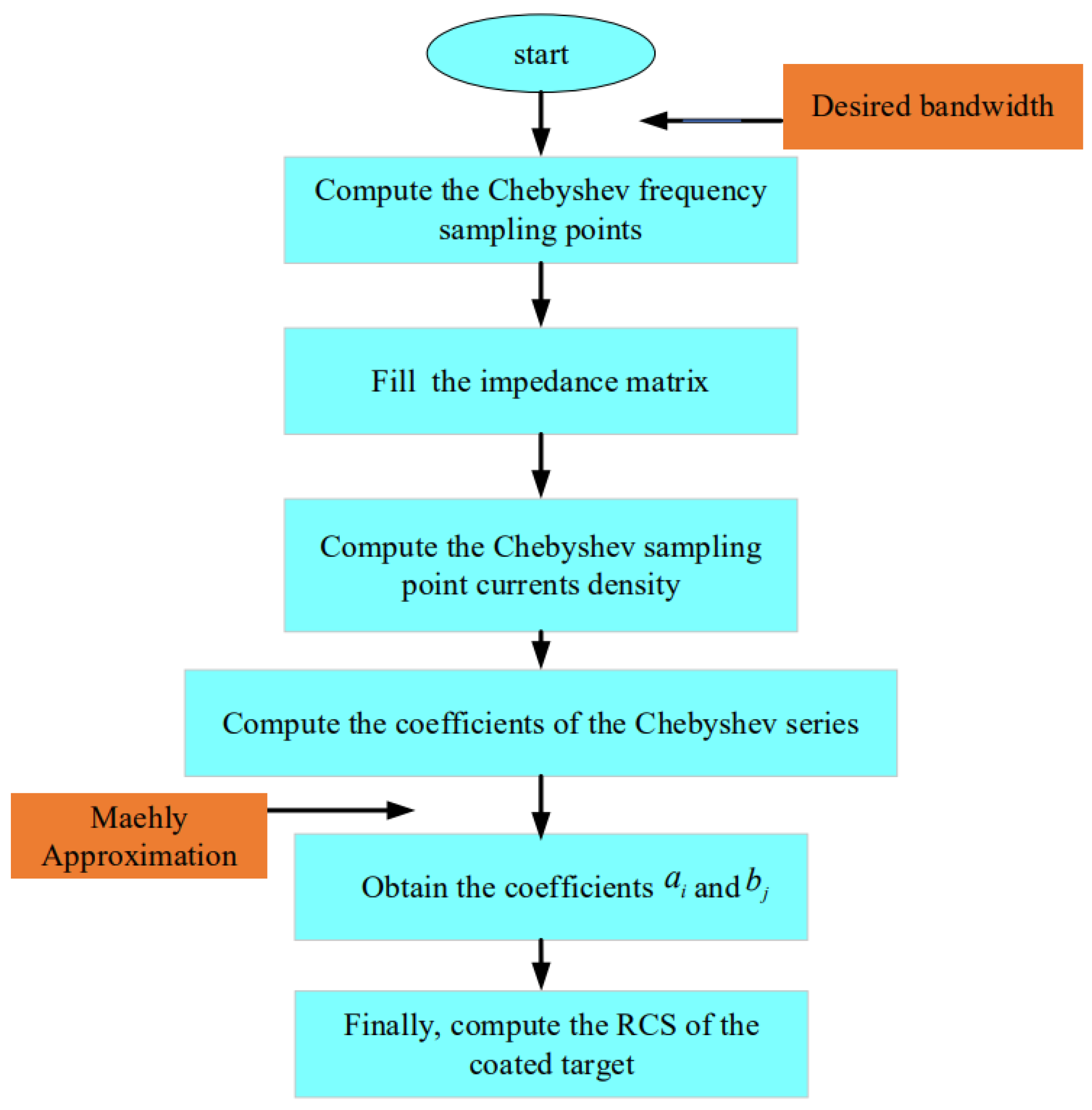
3. Hybrid EFIE-PMCHWT-CAT

When we predict the RCS for wide-band EM scattering, the traditional MoM based on the EFIE-PMCHWT integer equation needs to calculate the current value of every frequency point. The computation time is greatly increased. By introducing the Chebyshev approximation technique, the hybrid EFIE-PMCHWT-CAT is implemented to achieve fast sweeping as follows:
Firstly, for the certain band k [ k a , k b ] , we calculate the Chebyshev points k ˜ e , shown in Equation (18). E represents the truncated order of the Chebyshev series.
k ˜ e = cos [ ( 2 e 1 ) π 2 E ] e = 1 , 2 , , E
Secondly, we calculate the Chebyshev frequency sampling points by making the coordinated transformation of k ˜ e from the interval [ 1 , 1 ] to the desired band [ k a , k b ] .
k e = 1 2 [ k ˜ e ( k 1 k 0 ) + ( k 0 + k 1 ) ] , k ˜ e [ 1 , 1 ]
The matrix Equation (17) can be noted:
Z ( k e ) I ( k e ) = V ( k e )
We obtian the Chebyshev sampling point currents density by solving Equation (20). By Chebyshev approximation, the current densities I J ( k ) , I M ( k ) , and I C ( k ) can be written as:
I J ( k ) l = 0 E 1 c l T l ( k ˜ e ) c 0 2
I M ( k ) r = 0 E 1 c r T r ( k ˜ e ) c 0 2
I C ( k ) p = 0 E 1 c p T p ( k ˜ e ) c 0 2
Among Equations (21)–(23), T l ( k ˜ e ) , T r ( k ˜ e ) , and T p ( k ˜ e ) are Chebyshev polynomials. c l , c r , and c p denote the unknown coefficients. They are defined as:
c ( l , r , p ) = 2 E e = 0 E I ( l , r , p ) ( k e ) T ( l , r , p ) ( k ˜ e )
T 0 ( k ˜ e ) = 1 , T 1 ( k ˜ e ) = k ˜ e
T e + 1 ( k ˜ e ) = 2 k ˜ e T e ( k ˜ e ) T e 1 ( k ˜ e ) , 2 e E
To improve the accuracy of the numerical results, we usually use Maehly approximation to replace the Chebyshev polynomial expansion of the currents. The substitution process is as follows:
I ( J , M , C ) ( k ) R L M ( k ˜ e ) = P L ( k ˜ e ) Q M ( k ˜ e )
P L ( k ˜ e ) = i = 0 L a i T i ( k ˜ e ) = a 0 T 0 ( k ˜ e ) + a 1 T 1 ( k ˜ e ) + + a L T L ( k ˜ e )
Q M ( k ˜ e ) = j = 0 M b j T j ( k ˜ e ) = b 0 T 0 ( k ˜ e ) + b 1 T 1 ( k ˜ e ) + + b M T M ( k ˜ e )
L and M denote the Chebyshev polynomial expansion order of the P L ( k ˜ e ) and Q M ( k ˜ e ) . E = L + 2 M . The unknown coefficients a i and b j can be obtained by:
{ a 0 = 1 2 b 0 c 0 + 1 2 j = 1 M b j c j a i = c i + 1 4 b i c 0 + 1 2 j = 1 M b j ( c j + i + c | j i | ) , i = 1 , 2 , , L
[ c L + c L + 2 c L 1 + c L + 3 c L M + 1 + c L + M + 1 c L + 1 + c L + 3   c L + c L + 4 c L M + 2 + c L + M + 1 c L + M 1 + c L + M + 1 c L + M 2 + c L + M + 2 c L + c L + 2 M ] × [ b 1 b 2 b M ] = 2 [ c L + 1 c L + 2 c L + M ]
We can calculate a i and b j , substituting into Equations (27)–(29), and obtain the currents densities at each frequency point, and then the RCS can be efficiently calculated for the expected frequency band.
To help readers understand the hybrid algorithm more clearly, a flowchart was made to show the total process, as shown in Figure 4.

4. Numerical Results and Error Estimation

In this section, to validate the accuracy and applicability of the hybrid method, we investigated the RCS of three coated targets. The Sub6 base station was used as a non-cooperative illuminator for the first and second examples. For the final example, a satellite illuminator was used to verify the result. All computations were carried out on a PC with an Intel Core i7-7700K CPU and 48.0 GB RAM.
Error analysis was performed for the L. The error function and Euclidean norm are given by [31]:
{ e r r o r = R C S i + 1 R C S i R C S i R C S i = p = 1 k | R C S i | 2 , i = 1 , 2 , , 7
In Equation (32), R C S i is the RCS value calculated by EFIE-PMCHWT-CAT-L = i. k represents the number of frequency points.

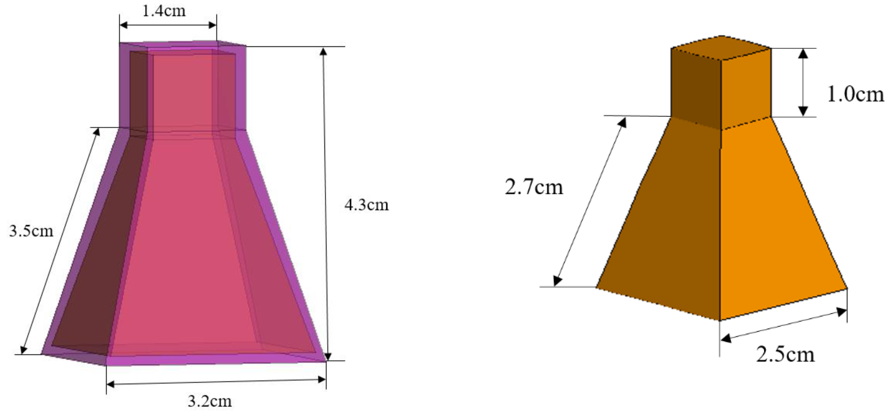
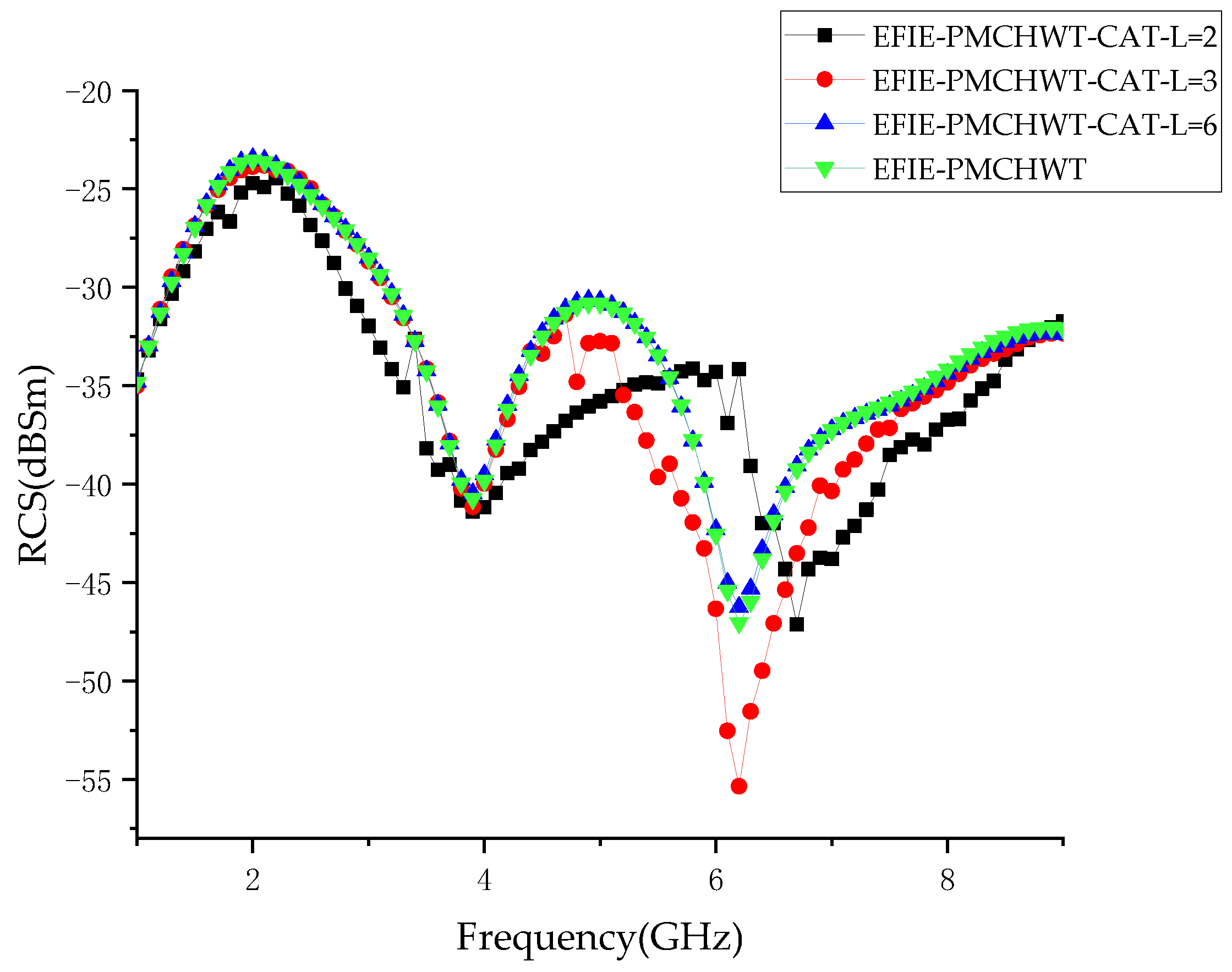
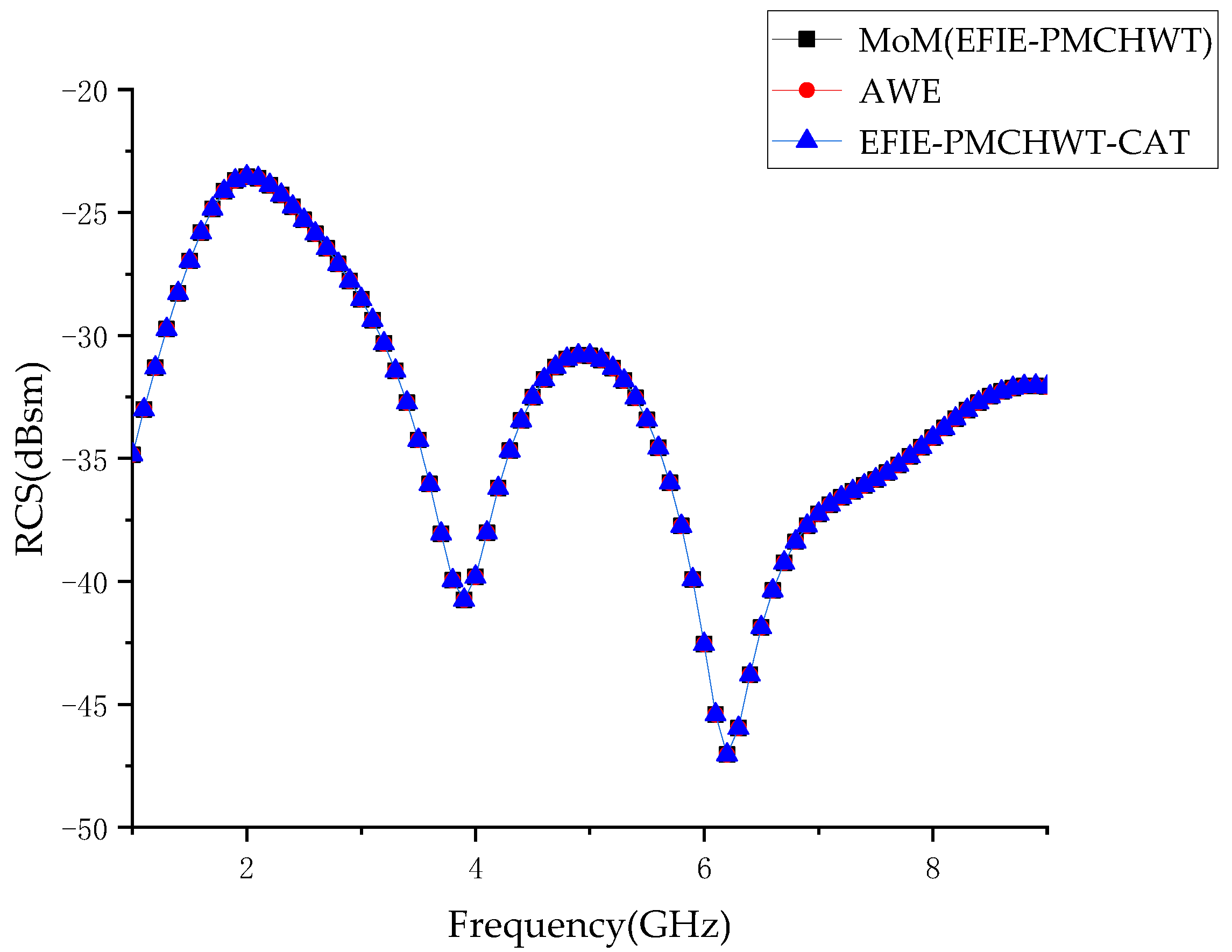
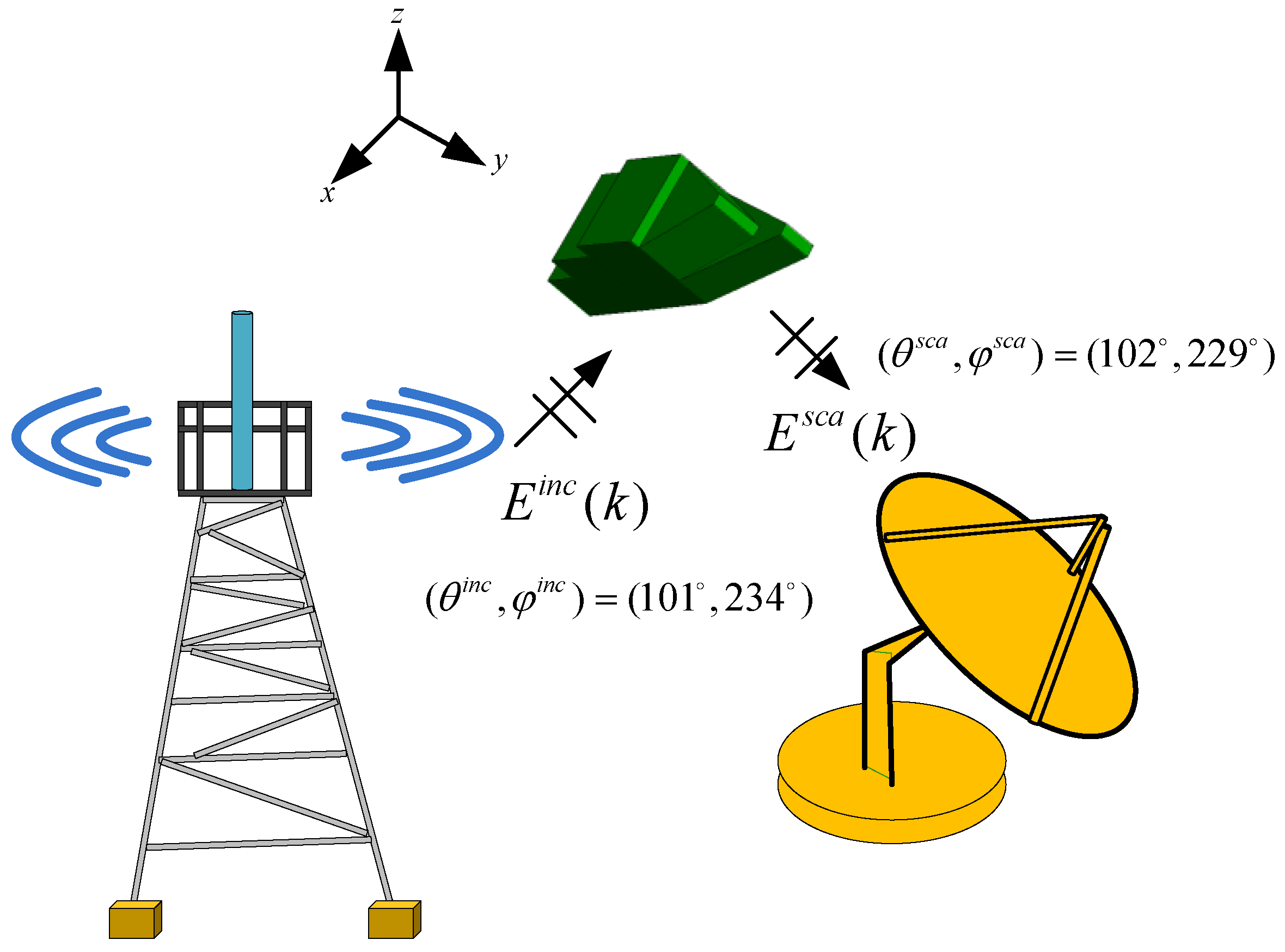
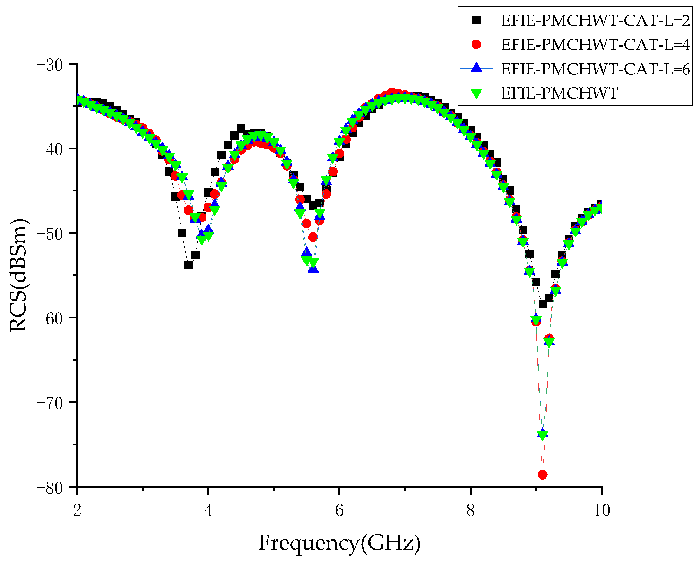
4.1. A Coated Composition
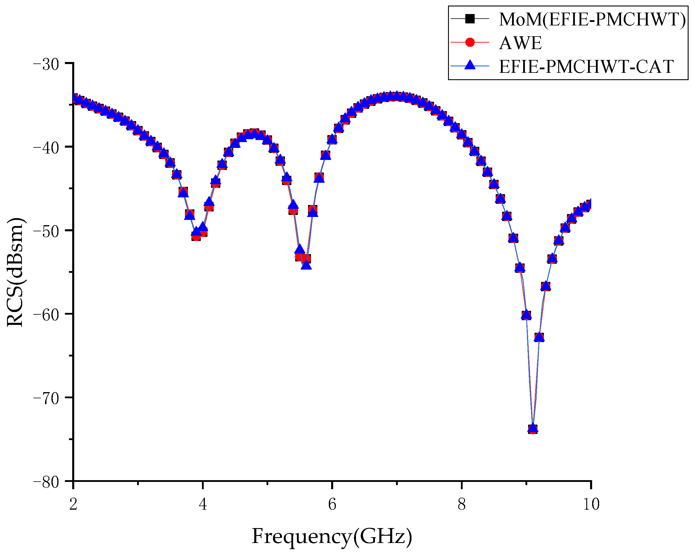
A coated target composed of a cuboid and a flare is shown in Figure 5. Through predicting the RCS of a simple target, the efficiency of the proposed EFIE-PMCHWT-CAT algorithm can be validated. The detailed size of the target is shown in Figure 6. The relative permittivity and dielectric loss tangent of the dielectric are 3.0 and 3.6, respectively. The perfect electric conductor and dielectric are modeled by 558 and 650 triangles, resulting in 2787 unknowns. It is illuminated by a θ θ polarized incident wave ( θ i n c , φ i n c ) = ( 101 , 234 ) . The scattering angle is ( θ s c a , φ s c a ) = ( 102 , 229 ) .
To compare the accuracy of the EFIE-PMCHWT and EFIE-PMCHWT-CAT, we computed the RCS frequency response from 1 GHz to 9 GHz with an interval of 0.1 GHz. Figure 7 shows the variation in the RCS with frequency. It is observed that the result is better with the increase in the order L. The MoM (EFIE-PMCHWT), AWE, and EFIE-PMCHWT-CAT numerical results are shown in Figure 8. The results of the EFIE-PMCHWT-CAT are in good agreement with those obtained by the MoM (EFIE-PMCHWT) and AWE.

4.2. A Coated Boat

Nowadays, fast prediction of the bistatic RCS of a complex target based on ocean scenarios is essential. In the second example, we consider a simplified boat (PEC) covered by the dielectric, and the posture and size of the model is illustrated in Figure 9 and Figure 10. The relative permittivity and dielectric loss tangent are 3.0 and 3.0. The surface of the perfect electrical conductor and dielectric is discretized with 568 and 698 triangles, which leads to 3027 unknowns. The working frequency is 2–10 GHz and the interval is 100 MHz. The incident angle is ( θ i n c , φ i n c ) = ( 101 , 234 ) , and the scattering angle is ( θ s c a , φ s c a ) = ( 102 , 229 ) .
Figure 11 shows the θ θ polarized wide-band RCS of frequency response from 2 GHz to 10 GHz obtained by the EFIE-PMCHWT and EFIE-PMCHWT-CAT with three different orders (L = 2,4,6). It is observed that the result is better with the increase in the order L. Figure 12 shows the calculated RCS of the model, where the results of the MoM (EFIE-PMCHWT), AWE, and EFIE-PMCHWT-CAT are compared. The results calculated with the three methods are basically consistent.

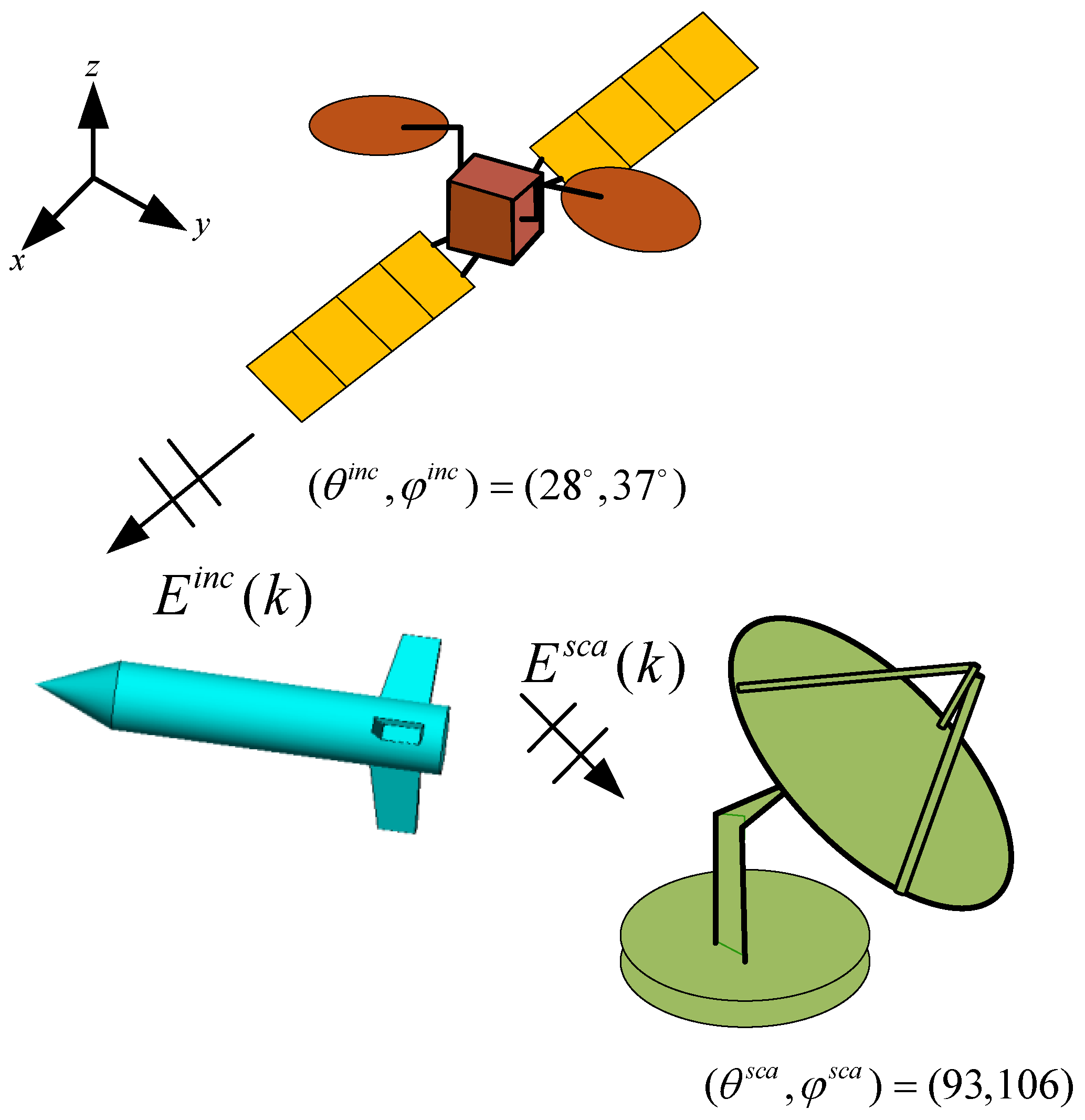
4.3. A Coated Missile Modet

In the third example, a missile is coated with the dielectric with a thickness of 3 mm. The posture and detailed size of the missile are shown in Figure 13 and Figure 14. The example further demonstrates that the hybrid algorithm is capable of providing clear and meaningful RCS for modern stealth equipment. The relative permittivity and dielectric loss tangent are 3.0 and 4.0. The surfaces of the perfect electrical conductor and dielectric are discretized with 618 and 964 triangles, resulting in 3819 unknowns. The incident angle is ( θ i n c , φ i n c ) = ( 28 , 37 ) and the scattering angle is ( θ s c a , φ s c a ) = ( 93 , 106 ) . The working frequency is 1 G–11 G, and the interval is 100 MHz.
Figure 15 shows the θ θ polarized RCS of the frequency response from 1 GHz to 11 GHz obtained by the EFIE-PMCHWT and EFIE-PMCHWT-CAT with three different orders (L = 1,3,7). It is observed that the result is better with the increase in the order. Figure 15 shows that the results of the EFIE-PMCHWT-CAT are in good agreement with those of the EFIE-PMCHWT. Validation of the proposed method is substantiated by comparing it with other approaches, such as the AWE and MoM (EFIE-PMCHWT). Figure 16 suggests that the result of the proposed method is in conformity with that of the AWE and MoM (EFIE-PMCHWT).
Using three examples, we found that the result is more accurate with a higher-order L. The reason is that the Chebyshev–Gauss sampling frequency points store more information on the currents. When the order L is low, Equations (28) and (29) show fewer expansion terms of the current density, leading to the difference between new currents and the original currents being large. According to Equation (33), an error analysis is shown in Figure 17 for the order L. The results suggest that the accuracy of the proposed algorithm can be guaranteed when the order L increases.
Table 1 shows the CPU time and memory requirement of the three examples. Table 1 shows that the CPU time gradually increases with the higher order L for EFIE-PMCHWT-CAT, but compared with the conventional MoM (EFIE-PMCHWT), the CPU time significantly decreases. When the results of EFIE-PMCHWT-CAT and the MoM (EFIE-PMCHWT) are in good agreement, the reduction in the CPU time of three examples is 71.8%, 68.4%, and 71.6%. The memory requirement is basically the same compared to EFIE-PMCHWT-CAT with MoM (EFIE-PMCHWT). By comparing the EFIE-PMCHWT-CAT and AWE, the memory requirement can achieve 75.9%, 77.8%, and 72.9% reductions for the three examples, and less CPU time is required.

5. Conclusions

An effective hybrid method is proposed to solve the wide-band EM scattering of the coated target based on the non-cooperative illuminator. By introducing the idea of the Chebyshev approximation technique, the CAT combined with the MoM based on EFIE-PMCHWT only calculates the electric and magnetic current coefficients at the Chebyshev–Gauss frequency sampling points. Compared with the traditional MoM, the proposed hybrid method can greatly reduce the CPU computation time, and the variation in the memory requirements may be negligible. Three examples are presented to show the efficiency and accuracy of the hybrid method. Since the wide-band electric and magnetic currents are obtained, the hybrid method can be used to compute the RCS at any angle and any frequency point. It should be noted that if the RCS curve contains a null value and sharp shape, the hybrid method with low order cannot obtain accurate results over the desired frequency band and a higher order is needed.

Author Contributions

Conceptualization, X.W.; data curation, F.Y.; formal analysis, C.L.; investigation, H.Z.; software, F.Y. and H.G.; supervision, X.W. and Y.L.; writing—original draft, F.Y.; writing—review and editing, F.Y. and X.W. All authors have read and agreed to the published version of the manuscript.

Funding

This work was supported in part by the National Natural Science Foundation of China under Grant No. 61871309, in part by the Fundamental Research Funds for the Central Universities under Grant ZDRC210, in part by the Natural Science Basic Research Program of Shaanxi (Program No. 2022-JM-398), in part by the 111 Project and in part by ZTE Industry-Academia-Research Cooperation Funds under Grant No. HC-CN-20211029015.

Data Availability Statement

This study did not report any data.

Conflicts of Interest

The authors declare no conflict of interest.

References

  1. Park, G.H.; Seo, Y.K.; Kim, H.N. Range-Doppler Domain-Based DOA Estimation Method for FM-Band Passive Bistatic Radar. IEEE Access 2020, 8, 56880–56891. [Google Scholar] [CrossRef]
  2. Li, M.Z.; Li, X.J. Detectability of maritime targets using passive radar based on satellite-borne illuminators. In Proceedings of the International Conference on Electronics Technology, Chengdu, China, 10–13 May 2019; pp. 273–276. [Google Scholar]
  3. Tsao, T.; Slamani, M.; Varshney, P.; Weiner, D.; Schwarzlander, H.; Borek, S. Ambiguity function for a bistatic radar. IEEE Trans. Aerosp. Electron. Syst. 1997, 33, 1041–1051. [Google Scholar] [CrossRef]
  4. Zhao, Z.; Wan, X.; Zhang, D. An Experimental Study of HF Passive Bistatic Radar Via Hybrid Sky-Surface Wave Mode. IEEE Trans. Antennas Propagat. 2013, 61, 415–424. [Google Scholar] [CrossRef]
  5. Guo, L.; Chen, Y.; Yang, S. Characteristic Mode Formulation for Dielectric Coated Conducting Bodies. IEEE Trans. Antennas Propagat. 2017, 65, 1248–1258. [Google Scholar] [CrossRef]
  6. Abutarboush, H.F.; Farooqui, M.F.; Shamim, A. Inkjet-Printed Wideband Antenna on Resin-Coated Paper Substrate for Curved Wireless Devices. IEEE Antennas Wirel. Propag. Lett. 2016, 15, 20–23. [Google Scholar] [CrossRef]
  7. Hou, X.; Xiang, L.I.; Wang, X. Some Observations and Thoughts about Reconfigurable Intelligent Surface Application for 5G Evolution and 6G. ZTE Commun. 2022, 20, 7. [Google Scholar]
  8. Rao, S.M.; Wilton, D.R.; Glisson, A.W. Electromagnetic scattering by surfaces of arbitrary shape. IEEE Trans. Antennas Propagat. 1982, 30, 409–418. [Google Scholar] [CrossRef]
  9. Liu, Z.J.; Chew, W.C.; Michielssen, E. Numerical modeling of dielectric- resonator antennas in a complex environment using the method of moments. IEEE Trans. Antennas Propagat. 2002, 50, 79–82. [Google Scholar]
  10. Ozturk, A.K.; Paknys, R.; Trueman, C.W. First-order singular basis functions for corner diffraction analysis using the method of moments. IEEE Trans. Antennas Propagat. 2009, 57, 3160–3168. [Google Scholar] [CrossRef]
  11. Umashankar, K.; Taflove, A.; Rao, S.M. Electromagnetic scattering by arbitrary shaped three-dimensional homogeneous lossy dielectric objects. IEEE Trans. Antennas Propagat. 1986, 34, 758–766. [Google Scholar] [CrossRef]
  12. Schaubert, D.H.; Wilton, D.R.; Glisson, A.W. A tetrahedral modeling method for electromagnetic scattering by arbitrarily shaped inhomogeneous dielectric bodies. IEEE Trans. Antennas Propagat. 1984, 32, 77–85. [Google Scholar] [CrossRef]
  13. Zhao, Y.; Tao, S.; Ding, D.; Chen, R. A Time-Domain Thin Dielectric Sheet (TD-TDS) Integral Equation Method for Scattering Characteristics of Tunable Graphene. IEEE Trans. Antennas Propagat. 2018, 66, 1366–1373. [Google Scholar] [CrossRef]
  14. Fan, T.Q.; Guo, L.X.; Lv, B.; Liu, W. An Improved Backward SBR-PO/PTD Hybrid Method for the Backward Scattering Prediction of an Electrically Large Target. IEEE Antennas Wirel. Propag. Lett. 2016, 15, 512–515. [Google Scholar] [CrossRef]
  15. Gao, H.W.; Yang, M.L.; Sheng, X.Q. A New SDIE Based on CFIE for Electromagnetic Scattering From IBC Objects. IEEE Trans. Antennas Propagat. 2020, 68, 388–399. [Google Scholar] [CrossRef]
  16. Zhao, R.; Hu, J.; Zhao, H.; Jiang, M.; Nie, Z. EFIE-PMCHWT-Based Domain Decomposition Method for Solving Electromagnetic Scattering From Complex Dielectric/Metallic Composite Objects. IEEE Antennas Wirel. Propag. Lett. 2017, 16, 1293–1296. [Google Scholar] [CrossRef]
  17. Zhao, W.J.; Li, L.W.; Xiao, K. Analysis of Electromagnetic Scattering and Radiation From Finite Microstrip Structures Using an EFIE-PMCHWT Formulation. IEEE Trans. Antennas Propagat. 2010, 58, 2468–2473. [Google Scholar] [CrossRef]
  18. Rao, S.M.; Cha, C.C.; Cravey, R.L.; Wilkes, D.L. Electromagnetic scattering from arbitrary shaped conducting bodies coated with lossy materials of arbitrary thickness. IEEE Trans. Antennas Propagat. 1991, 39, 627–631. [Google Scholar] [CrossRef]
  19. Zhang, Y.; Zhao, X.W.; Donoro, D.G.; Ting, S.W.; Sarkar, T.K. Parallelized Hybrid Method With Higher-Order MoM and PO for Analysis of Phased Array Antennas on Electrically Large Platforms. IEEE Trans. Antennas Propagat. 2010, 58, 4110–4115. [Google Scholar] [CrossRef]
  20. Manić, A.B.; Smull, A.P.; Rouet, F.H.; Li, X.S.; Notaroš, B.M. Efficient Scalable Parallel Higher Order Direct MoM-SIE Method With Hierarchically Semiseparable Structures for 3-D Scattering. IEEE Trans. Antennas Propagat. 2017, 65, 2467–2478. [Google Scholar] [CrossRef]
  21. Jeong, Y.R.; Hong, I.P.; Lee, K.W.; Lee, J.H.; Yook, J.G. Fast Frequency Sweep Using Asymptotic Waveform Evaluation Technique and Thin Dielectric Sheet Approximation. IEEE Trans. Antennas Propagat. 2016, 64, 1800–1806. [Google Scholar] [CrossRef]
  22. Yang, J.; Sarkar, T.K. Interpolation/Extrapolation of Radar Cross-Section (RCS) Data in the Frequency Domain Using the Cauchy Method. IEEE Trans. Antennas Propag. 2007, 55, 2844–2851. [Google Scholar] [CrossRef]
  23. Wang, X.; Zhang, S.; Xue, H.; Gong, S.X.; Liu, Z.L. A Chebyshev approximation technique based on AIM-PO for wide-band analysis. IEEE Antennas Wirel. Propag. Lett. 2016, 15, 93–97. [Google Scholar] [CrossRef]
  24. Wang, X.; Gong, H.X.; Zhang, S.; Liu, Y.; Yang, R.P.; Liu, C.H. Efficient RCS computation over a broad frequency band using subdomain MoM and Chebyshev approximation technique. IEEE Access 2020, 8, 33522–33531. [Google Scholar] [CrossRef]
  25. Bednarz, C.; Mantzke, A.; Leone, M. Efficient FEM-Based Modal Circuit Representation of Arbitrarily Shaped Plate Pairs. IEEE Trans. Electromagn. Compat. 2014, 56, 990–993. [Google Scholar] [CrossRef]
  26. Hu, F.G.; Wang, C.F. Preconditioned Formulation of FE-BI Equations With Domain Decomposition Method for Calculation of Electromagnetic Scattering From Cavities. IEEE Trans. Antennas Propag. 2009, 57, 2506–2511. [Google Scholar]
  27. Dang, V.; Nguyen, Q.M.; Kilic, O. GPU Cluster Implementation of FMM-FFT for Large-Scale Electromagnetic Problems. IEEE Antennas Wirel. Propag. Lett. 2014, 13, 1259–1262. [Google Scholar] [CrossRef]
  28. Yang, M.L.; Wu, B.Y.; Gao, H.W.; Sheng, X.Q. A Ternary Parallelization Approach of MLFMA for Solving Electromagnetic Scattering Problems With Over 10 Billion Unknowns. IEEE Trans. Antennas Propag. 2019, 67, 6965–6978. [Google Scholar] [CrossRef]
  29. Gao, H.W.; Hao, J.W.; Pan, X.M. Application of Interpolative Decomposition to FE-BI-MLFMA for Fast Computation of Monostatic Scattering from 3-D Complex Composite Objects. IEEE Antennas Wirel. Propag. Lett. 2014, 13, 1490–1493. [Google Scholar]
  30. Kai, H.; He, Z.L.; Liang, C.H. Efficient Analysis of Antenna Around Electrically Large NURBS Platform With Accelerating MOM-PO Method. IEEE Antennas Wirel. Propag. Lett. 2010, 9, 134–137. [Google Scholar]
  31. Barati, P.; Ghalamkari, B. Semi-analytical solution of electromagnetic wave scattering from PEC strip located at the interface of dielectric-TI media. Eng. Anal. Bound. Elem. 2021, 123, 62–69. [Google Scholar] [CrossRef]
Figure 1. Illustration of the passive bistatic radar system based on a non-cooperative illuminator.
Electronics 12 00923 g001
Figure 2. Configuration of perfect electrical conducting coated with dielectric.
Electronics 12 00923 g002
Figure 3. (a) Equivalent external problem (b); equivalent interior situation.
Electronics 12 00923 g003
Figure 4. The EFIE-PMCHWT-CAT flowchart.
Electronics 12 00923 g004
Figure 5. The posture of the coated target based on Sub6 base station illuminator.
Electronics 12 00923 g005
Figure 6. The geometry of the coated target.
Electronics 12 00923 g006
Figure 7. RCS frequency response of the coated target by using three different orders of EFIE-PMCHWT-CAT and EFIE-PMCHWT.
Electronics 12 00923 g007
Figure 8. RCS frequency response of the coated composition of the MoM (EFIE-PMCHWT), AWE, and EFIE-PMCHWT-CAT.
Electronics 12 00923 g008
Figure 9. The posture of the coated boat based on Sub6 base station illuminator.
Electronics 12 00923 g009
Figure 10. The geometry of the coated boat.
Electronics 12 00923 g010
Figure 11. RCS frequency response of the coated boat by using three different orders of EFIE-PMCHWT-CAT and EFIE-PMCHWT.
Electronics 12 00923 g011
Figure 12. RCS frequency response of the coated boat of the MoM (EFIE-PMCHWT), AWE, and EFIE-PMCHWT-CAT.
Electronics 12 00923 g012
Figure 13. The posture of the coated missile based on satellite-borne illuminator.
Electronics 12 00923 g013
Figure 14. The geometry of the coated missile.
Electronics 12 00923 g014
Figure 15. RCS frequency response of the coated missile by using three different orders of EFIE-PMCHWT-CAT and EFIE-PMCHWT.
Electronics 12 00923 g015
Figure 16. RCS frequency response of the coated missile of the MoM (EFIE-PMCHWT), AWE, and EFIE-PMCHWT-CAT.
Electronics 12 00923 g016
Figure 17. Convergence curves for order L.
Electronics 12 00923 g017
Table 1. The total CPU time and memory requirement of three examples.
ExamplesMethodMemory (MB)CPU Time (s)
Coated compositionEFIE-PMCHWT-CAT_L = 2
EFIE-PMCHWT-CAT_L = 3
338.0
338.3
1296.9
1621.6
EFIE-PMCHWT-CAT_L = 6
MoM (EFIE-PMCHWT)
338.4
327.4
3477.2
12,345.3
AWE1343.66439.2
Coated boatEFIE-PMCHWT-CAT_L = 2395.31471.5
EFIE-PMCHWT-CAT_L = 4395.62382.9
EFIE-PMCHWT-CAT_L = 6
MoM (EFIE-PMCHWT)
395.7
395.2
4680.8
14,819.3
AWE1768.97986.5
Coated missileEFIE-PMCHWT-CAT_L = 1 1186.94225.5
EFIE-PMCHWT-CAT_L = 3
EFIE-PMCHWT-CAT_L = 7
MoM (EFIE-PMCHWT)
1187.4
1188.2
1186.6
6430.7
7185.7
25,319.6
AWE4378.612,768.5
Disclaimer/Publisher’s Note: The statements, opinions and data contained in all publications are solely those of the individual author(s) and contributor(s) and not of MDPI and/or the editor(s). MDPI and/or the editor(s) disclaim responsibility for any injury to people or property resulting from any ideas, methods, instructions or products referred to in the content.

