1. Introduction
Unmanned Aerial Vehicles (UAVs) are employed for operations where pilots’ lives may be at risk [
1,
2]. Research on UAVs for numerous applications is currently carried out [
3,
4,
5]. UAVs embody various sensors for monitoring the environment and performing real-time decision-making [
6]. Due to the fact that UAVs are intended to operate in hazardous environments, the most important issue is planning the path of their mission [
7]. Accordingly, the need arises for on-board sensors to avoid collisions with any type of obstacle even with other UAVs [
8,
9]. Thus, sophisticated Collision Avoidance Systems (CASs) are of primary importance for the efficient performance of a UAV [
10].
The collision avoidance procedure incorporates two stages [
1]: the perception of the environment and, after that, the probable required action. Perception is carried out using various sensors, passive or active, while the required actions for collision avoidance are categorized as [
1]:
Geometric;
Force-field;
Optimized;
Sense and Avoid.
The capability of having many sensors on board increases the possibility of improving the performance of a CAS system, but, on the other hand, it makes the UAV heavier and the required data processing time-consuming [
11]. A high-performance CAS system should incorporate the monitoring of each of the sensors for optimal performance. Thus, a kind of Sensor Autonomous Integrity Monitoring (SAIM) is required in correspondence with the Receiver Autonomous Integrity Monitoring (RAIM) systems [
12].
During the last decades, a procedure has been developed to assess the integrity of the global positioning system (GPS) signals recorded with a GPS receiver system. The technique is called Receiver Autonomous Integrity Monitoring (RAIM) [
12,
13,
14,
15]. The integrity of the GPS receiver signals is of crucial importance in GPS applications, such as in aviation or marine navigation, which are characterized as safety critical. The GPS system does not incorporate any technical procedure to correct possible inaccurate information transmitted by its systems. Simultaneously, a receiver of the GPS signals cannot be aware of this inaccurate information and will not try to correct its navigational capabilities. For GPS receivers, RAIM availability usually is tested when fewer than 24 GPS satellites are available by employing mathematical prediction approaches implemented at ground stations.
Currently, Time-Receiver Autonomous Integrity Monitoring (T-RAIM) algorithms assess the reliability of the timing solution provided by a Global Navigation Satellite System (GNSS) timing receiver. A potential T-RAIM approach developed in a multi-constellation context is described in [
12]. In this work, measurements from several GNSS constellations provide increased redundancy at the cost of increased system complexity. Integrity requirements for the airborne use of GPS are reviewed in [
13]. This is followed by the description of a baseline fault detection algorithm which is shown to be capable of satisfying tentative integrity requirements. Preliminary performance results for the baseline fault detection algorithm are presented in [
14] along with the potential of RAIM techniques for achieving GPS integrity. The focus of the paper in [
15] is to implement a fault detection and exclusion algorithm in a software GPS receiver in order to provide timely warnings to the user when it is not advisable to use the GPS system for navigation. Several GPS-related systems also provide integrity signals separate from the GPS. Among these is the Wide Area Augmentation System (WAAS) [
16], which is an air navigation aid developed by the Federal Aviation Administration to augment the GPS with the goal of improving its accuracy, integrity, and availability.
A cooperative integrity monitoring (CIM) algorithm is proposed in [
17] which can be applied to many existing multi-sensor cooperative positioning algorithms. In [
18], an integrity monitoring framework is proposed that can assess the quality of multimodal data from exteroceptive sensors. The problem of fault detection, isolation, and adaptation (FDIA) is addressed in [
19] for navigation systems on board passenger vehicles.
In this paper, a method for monitoring the operational integrity of each one of the sensors on board the UAV is proposed. It is assumed that five sensors of the same type are employed on the UAV in order to combine their decisions regarding the physical quantities such as distance and angle required to assess the collision parameters. The method is based on comparing the decision of the sensor under inspection with the decision obtained after fusing the decisions of the other four sensors, the operation of which is assumed to be normal. The proposed Sensor Autonomous Integrity Monitoring (SAIM) approach in fact employs the property which emerges from decision fusion methods [
20,
21], which states that at least three sensors give a decision that is more reliable than the most reliable sensor of the three used in the fusion procedure. If the inspected sensor is assessed to convey poor or unreliable information, its decision is ignored or otherwise, the sensor is gated. A complementary experiment with a total of four sensors, one of which has low performance, was also conducted.
This manuscript is organized as follows. In
Section 2, the basics of UAV collision avoidance sensors are given. The RAIM essentials are presented in
Section 3. The proposed SAIM method for UAVs is analyzed in
Section 4. The experimental results are presented in
Section 5, while the conclusions are drawn in
Section 6.
2. Basics of UAV Collision Avoidance Sensors
In order for an unmanned vehicle to be able to navigate autonomously avoiding obstacles, a series of procedures are necessary such as the detection of the obstacle, its avoidance, planning continuously the path to be followed, localization, and control systems management [
22]. In general, the environment in which a UAV is operating is dynamic, and there are limitations for the on-board payload, which, however, is very crucial for the operation of the UAV. Furthermore, severe weather conditions can dramatically reduce the operational capabilities of the UAV. Obstacle detection and collision avoidance become more challenging tasks if multiple UAVs or multiple moving obstacles are considered [
11].
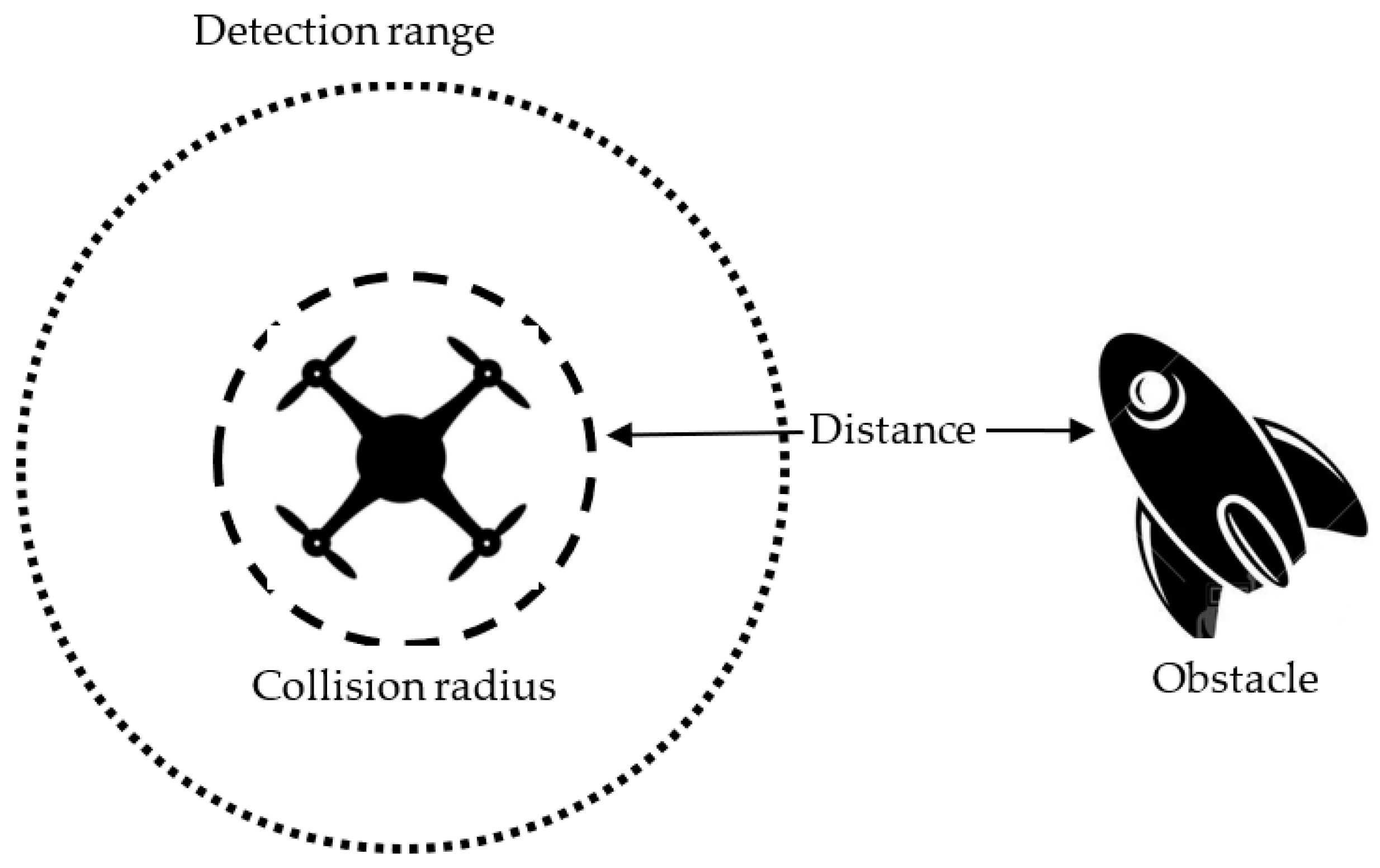
The collision radius R
c determines the minimum distance from a UAV which is adequate to avoid a collision (
Figure 1). The detection range is much larger (
Figure 1), and the larger its length is, the better the UAV can resolve, detect, and avoid a collision.
A collision avoidance system (CAS) for a UAV is responsible for ensuring that no collisions with any obstacle will happen whether moving or stationary. In this work, we take advantage of the available information given for each sensor to sense the obstacle, and then we improve the detection phase of the system trying to assess the risk. Based on this, the collision avoidance module performs the necessary calculations to compute the amount of deviation needed from the original path to avoid the potential collision. Collision avoidance algorithms are categorized in [
1] into the following major methods:
- (1)
Geometric methods, which work by computing the distance between the UAV and the obstacle.
- (2)
Force field methods, in which the main idea is inspired by attractive or repulsive electric forces that exist among charged objects. In a swarm of drones, each UAV node is considered a charged particle.
- (3)
Optimization-based methods, which aim at finding the optimal or near-optimal solutions for path planning.
- (4)
Sense-and-avoid methods, which mainly focus on reducing the computational cost with a short response time.
In this work, the geometric approach is followed. Geometric approaches rely on computing the time to collision by utilizing the distances between the UAVs and their velocities. In [
23], the authors studied geometry-based collision avoidance strategies for a swarm of UAVs. The proposed approach uses line-of-sight vectors in combination with relative velocity vectors while considering the dynamic constraints of a formation. By calculating a collision envelope, each UAV can determine the available direction for avoiding a collision and decide whether the formation can be kept while avoiding collisions. In [
24], the authors presented a new methodology of the Fast Geometric Avoidance Algorithm (FGA) based on kinematics, the probability of collisions, and navigational limitations by combining geometric avoidance and the selection of start time from critical avoidance. In a multiple obstacles scenario, instead of avoiding the obstacles simultaneously, FGA can assign different threat levels to obstacles based on the critical time for avoidance and avoid them sequentially and, hence, increase the avoidance success rate.
In the scenario of this work, the sensors are considered to be distributed in a very small space in the UAV. Usually, each sensor is of a different type from the others and monitors a different and complementary region. In our scenario, we assume that a specific region outside the UAV is monitored periodically by four or five active sensors simultaneously of different types (Radar, Lidar, Near-Infrared). Accordingly, all the sensors can be considered active, so that they will operate in any environmental and weather conditions. Furthermore, it is assumed that their quality characteristics are similar. The variation in the quality characteristics is mainly due to the different types of sensors (Radar, Lidar, Near-Infrared, etc.)
3. RAIM Essentials
Receiver Autonomous Integrity Monitoring (RAIM) approaches provide monitoring for the integrity of GPS signals which are employed in numerous aviation applications. In order to achieve integrity monitoring of the signals of a sensor, a minimum of five satellites visible to the sensor with satisfactory geometry must be utilized. The sensor or receiver sends a signal to the pilot regarding its integrity. It is very important for aviation receivers to possess RAIM capabilities to support safety issues. First of all, the receiver availability is a function of the geometry of the satellite constellation as well as the environmental conditions.
An enhanced version of RAIM employed in some receivers is known as fault detection and exclusion (FDE). It uses a minimum of six measurements which can be achieved with six satellites or five satellites with baro-aiding to not only detect a possible faulty satellite. The goal of fault detection is to detect the presence of a positioning failure. GNSS differs from traditional navigation systems because the satellites and areas of degraded coverage are in constant motion. Therefore, if a satellite fails or is taken out of service for maintenance, it is not immediately clear which areas of the airspace will be affected, if any. The location and duration of these deficiencies can be predicted with the aid of computer analysis and reported to pilots during the pre-flight planning process.
Because RAIM operates autonomously, that is without the assistance of external signals, it requires redundant pseudo-range measurements. To obtain a 3D position solution, at least four measurements are required. To detect a fault, at least five measurements are required, and to isolate and exclude a fault, at least six measurements are required. However, often more measurements are needed depending on the satellite geometry. Typically, there are seven to twelve satellites in view. The test statistic used is a function of the pseudo-range measurement residual (the difference between the expected measurement and the observed measurement) and the amount of redundancy. The test statistic is compared with a threshold value, which is determined based on the requirements for the probability of false alarm (Pfa) and the expected measurement noise. In aviation systems, the Pfa is fixed at 1/15,000.
Various attempts have been made in the past to support autonomous integrity monitoring of sensors employed for collision avoidance. The cooperative integrity monitoring (CIM) algorithm proposed in [
17] can fully exploit the global navigation satellite system (GNSS) data and inter-vehicle measurements data to improve the detection and isolation of faulty measurements due to multipath or non-line of sight (NLOS). An integrity monitoring framework that can assess the quality of multimodal data from exteroceptive sensors has been proposed in [
18]. The proposed multisource coherence-based integrity assessment framework is capable of handling highway as well as complex semi-urban and urban scenarios. The work in [
19] addresses the problem of fault detection, isolation, and adaptation (FDIA) in navigation systems on board passenger vehicles. It succeeds to prevent malfunctions in systems such as advanced driving assistance systems and autonomous driving functions that use data provided by the navigation system. The integrity of the estimation of the vehicle position provided by the navigation system is continuously monitored and assessed.
4. Proposed SAIM in UAVs
Sensor Autonomous Integrative Monitoring is crucial for the effective operation of the collision avoidance system of the UAV. In a similar manner as in RAIM, each sensor in the UAV must check itself for the reliability of the decisions taken. If the decisions taken by a sensor are not reliable, then the specific sensor is to be deactivated. The reliability of the sensor is accessed by comparing its characteristics Pd and Pf with the performance at the fusion center.
The Sensor Autonomous Integrity Monitoring (SAIM) method proposed in this work is explained in four distinctive stages. It is assumed that five different sensors are on board to assess the distance and the relative movement of the obstacle with respect to the UAV. A complementary simulation experiment with a total of four sensors, one of which has low performance, was also conducted.
4.1. Performance Characteristics of Each Separate Sensor
Each separate sensor is measuring the geometric attributes of speed and distance of the obstacle while it is operating under specific quality characteristics. These characteristics are uniquely selected in this work to be the probability of detection and the probability of false alarm for the measured quantities. Consequently, we consider that we have a two-hypothesis testing problem with corresponding to obstacle presence and to obstacle absence (free space). There is no knowledge of a priori probabilities, so they are not taken into consideration, or otherwise, they are assumed equal.
4.2. Fusion Performance in Parallel Configuration
A Fusion Center (FC) operates on board and is responsible for two different tasks:
Implement a Neyman–Pearson (N-P) test using all five decisions except one (the k-th, k = 1 to 5).
Decide for gating the k-th sensor if a specific condition reports the k-th sensor as being unreliable.
Let
be the decision of the
j-th sensor having considered all the observations regarding the obstacle distance and velocity. If the decision of the
j-th sensor favors hypothesis
, then
, otherwise,
. All five decisions are transmitted to the Fusion Center and are available for processing. Let (
) be the operating characteristics or otherwise the quality of the decision of the
j-th sensor. The Fusion Center implements the N-P test using all four of the five decisions based on the Likelihood Ratio (LR) test:
where
is a
row vector with entries being the decisions of the four individual sensors (one is excluded), and
t the threshold to be determined with the desirable probability of false alarm at the Fusion Center
, [
20], i.e.,
Since the decisions of each sensor are independent from those of the other sensors, the LR test from (1) gives
For the implementation of the N-P, the computation of ) is required. Taking into consideration the independence of the sensors, we obtain, for easier evaluation, the distribution ) which can be expressed as the convolution of the individual
Accordingly, the LR assumes two values. Either , when with probability under hypothesis and probability under hypothesis , or , when with probability under hypothesis and probability under hypothesis .
At the Fusion Center, the probability of false alarm is obtained as
where
is a threshold chosen to satisfy (4) for a given
. Similarly, the probability of detection at the Fusion Center is
We are interested to know if a configuration of four sensors can provide, by means of the N-P test, a
pair such that
In [
20], it is proved, in the form of a theorem, that the condition (6) can be satisfied if the number of sensors N is greater than two, and all the sensors are characterized by the same
pair.
Theorem 1 ([
20])
. In a configuration of similar sensors, all operating at the same
, the randomized N-P test at the Fusion Center can provide a satisfying (15) if
.
More precisely, for, the randomized N-P test can be fixed so that 4.3. Conditions for a Sensor Gating
According to the previous theorem, if the Fusion Center is employing four sensors, it can give a probability of false alarm at the Fusion Center smaller than that of the probability of false alarm at the fifth sensor under testing, and simultaneously a larger than that of the probability of detection at the fifth sensor under testing. In this case, this fifth sensor can be considered as unreliable and be gated (excluded) for evaluating the Fusion Center performance.
4.4. Total Configuration of the SAIM Method
The configuration approach for applying the proposed SAIM method for each of the available sensors is as follows:
Each of the five sensors is excluded, and the performance of the Fusion Center is evaluated by employing the other four sensors. It is required that:
Procedure a. is repeated for all five sensors.
In the case of dissimilar sensors, we have to record the performance of the Fusion Center when the k-th sensor is excluded.
The SAIM configuration leads the specific
k-th sensor among the five sensors to be autonomously disabled with a special signal for its participation in the decision of the Fusion Center when this sensor finds out that:
This means that the k-th sensor cannot contribute significant information to the Fusion Center if its characteristic probability of false alarm is larger or equal to that achieved by the Fusion Center with four sensors while its probability of detection is well below the achieved corresponding probability of detection at the Fusion Center of the UAV. If condition (8) is not valid for any one of the five sensors, then all available sensors are employed to contribute to the Fusion Center for its final decision.
5. Experimental Results
The SAIM procedure is demonstrated experimentally by means of the numerical evaluation of the performance at the Fusion Center. For this purpose, five sensors are considered on board the UAV having the quality characteristics (
and
) as depicted in
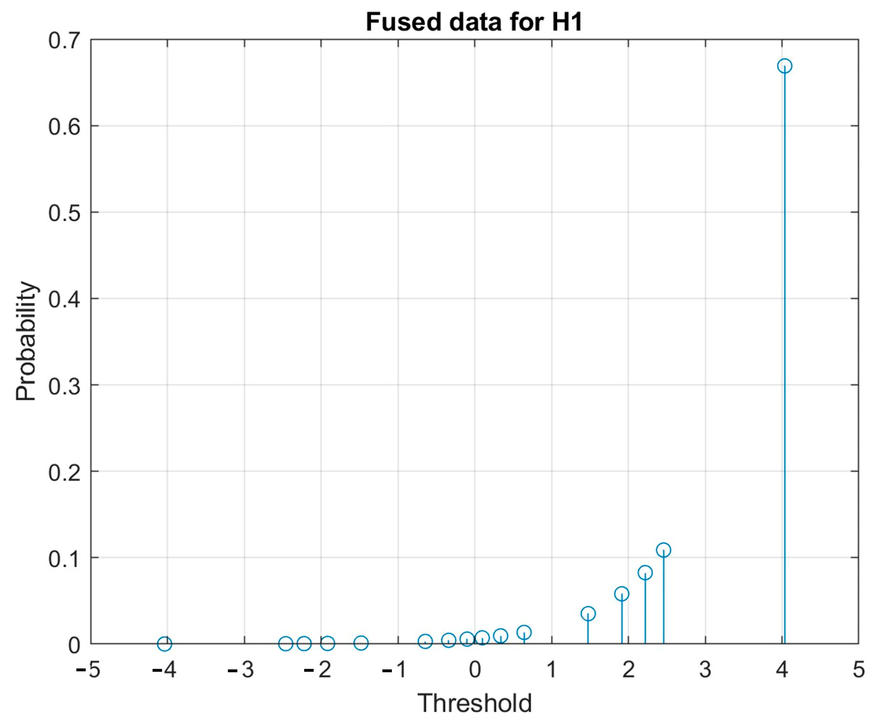
Table 1. As it was previously stated, the evaluation of the distribution
), given the independence of the sensors, can be expressed as the convolution of the individual
). Accordingly, the distribution
) is graphically depicted in
Figure 2. Only the first to fourth sensors have been considered for evaluating
). In a similar way, the distribution of
) can be expressed as the convolution of the individual
), and this is graphically depicted in
Figure 3. In this case as well, only the first to fourth sensors have been considered for evaluating
). In
Table 2 are given analytically all possible threshold positions at the Fusion Center and the achieved
and
.
The achieved
and
for each threshold are evaluated by summing all the terms from the threshold position to the right of the distributions in
Figure 2 and
Figure 3, respectively. According to the results in
Table 1 and
Table 2, the quality characteristics of the fifth sensor are far exceeded by the performance of the Fusion Center, which employs the other four sensors (first to fourth). The 13th threshold, which is equal to 0.012, gives a
, which is smaller than the
. Simultaneously, for the same threshold, the
, which is very high in contrast to the
, which equals 0.85. The results in
Table 2 were obtained considering the fifth sensor in
Table 1 as inactive.
Mathematic evaluations are carried out using simulation software built in MATLAB.
In an attempt to assess the information contribution of the fifth sensor to the final decision of the Fusion Center, this sensor was considered together with the other four to evaluate the
and the
. As depicted in
Table 3, the fifth sensor does not add any significant information to the Fusion Center since at the threshold No. 28, the
while the achieve
, which is 0.9997, was reached using only the first four sensors (
Table 2, threshold 13). Thus, the fifth sensor must be ignored since the information it conveys regarding the specific incident is poor or unreliable.
In order to further strengthen the reliability of the proposed SAIM method, another example is presented proving that a sensor with low performance has to be ignored in the decision fusion procedure in the Fusion Center. In this example, a total of four sensors are employed assuming that one of them has quite poor performance concerning its
Pf and
Pd. Accordingly, in
Table 4 are given the operating characteristics of the four sensors with the fourth one being poorly-operating. In
Table 5, the only threshold suitable for operating the Fusion Center with performance better than the best of the sensors is threshold No. 4. As it is shown in
Table 6, the fourth poorly-operating sensor cannot add any important threshold discrimination capabilities since the eighth threshold is the same as the fourth one in
Table 5, and it is equivalent to the ninth threshold.
6. Conclusions
In this paper, the SAIM method for monitoring the operation integrity of each one of the sensors on board the UAV was presented. The assumed navigation scenario included the involvement of five sensors for monitoring collision avoidance. The five sensors have similar quality characteristics, and their decisions regarding the physical quantities such as the distance and angle required to assess collision parameters are combined at the Fusion Center of the UAV. The quality characteristics of each sensor is monitored against the performance at the Fusion Center when it employs the decision of the other four sensors. Experimental results reveal a reliable approach for Sensor Autonomous Integrity Monitoring. The method can be easily extended to a larger number of sensors.
According to the analyzed results in
Table 1 and
Table 2, the quality characteristics of the fifth sensor are far exceeded by the performance of the Fusion Center, which employs the other four sensors (first to fourth). The information contribution of the fifth sensor, if it is taken into consideration in the final decision of the Fusion Center, is proved to be negligible due to the poor or unreliable performance of this specific sensor. This is evident from the comparison of the results in
Table 2 and
Table 3, where the fifth sensor does not add any significant information to the Fusion Center and thus it must be ignored. A complementary experiment with a total of four sensors, one of which has low performance, was also conducted and resulted in similar conclusions as demonstrated in
Table 4,
Table 5 and
Table 6.
The important requirement for applying the proposed SAIM method is that the Fusion Center on board the UAV must be continuously updated with the quality characteristics (probability of false alarm and probability of detection—()) of each separate sensor. Thus, each sensor must transmit this information frequently to the Fusion Center. The quality characteristics of a specific sensor can be estimated based on the results of the sensor’s monitoring with respect to the Fusion Center decisions.


