Review

Multi-Object Tracking with mmWave Radar: A Review

Global Big Data Technologies Centre (GBDTC), University of Technology Sydney (UTS), Sydney, NSW 2122, Australia
*
Author to whom correspondence should be addressed.
Electronics 2023, 12(2), 308; https://doi.org/10.3390/electronics12020308
Submission received: 26 November 2022 / Revised: 2 January 2023 / Accepted: 4 January 2023 / Published: 6 January 2023
(This article belongs to the Topic Radar Signal and Data Processing with Applications)

Abstract

:
The boundaries of tracking and sensing solutions are continuously being pushed. A stimulation in this field over recent years is exploiting the properties of millimeter wave (mmWave) radar to achieve simultaneous tracking and sensing of multiple objects. This paper aims to provide a critical analysis of the current literature surrounding multi-object tracking and sensing with short-range mmWave radar. There is significant literature available regarding single-object tracking using mmWave radar, demonstrating the maturity of single-object tracking systems. However, innovative research and advancements are also needed in the field of mmWave radar multi-object tracking, specifically with respect to uniquely identifying multiple target tracks across an interrupted field of view. In this article, we aim to provide an overview of the latest progress in multi-target tracking. In particular, an attempt to phrase the problem space is made by firstly defining a typical multi-object tracking architecture. We then highlight the areas for potential advancements. These areas include sensor fusion, micro-Doppler feature analysis, specialized and generalized activity recognition, gait, tagging and shape profile. Potential multi-object tracking advancements are reviewed and compared with respect to adaptability, performance, accuracy and specificity. Although the majority of the literature reviewed has a focus on human targets, most of the methodologies can be applied to targets consisting of different profiles and characteristics to that of humans. Lastly, future research directions are also discussed to shed light on research opportunities and potential approaches in the open research areas.

1. Introduction

Millimeter wave (mmWave) radars have been widely studied over recent years for multi-object tracking and sensing. The potential and motivation for mmWave radars in this field is primarily driven by the micro-Doppler information that can be extrapolated. Micro-Doppler generally refers to the Doppler information generated by movements of individual parts of a particular target [1]. The micro-Doppler features can be exploited to determine characteristics of multiple targets for tracking and sensing purposes. The identified characteristics can ultimately be translated into sub-millimeter individual movements of the targets. This is attributed to the high sensitivity of mmWave radars empowered by their extremely short wavelength.
The research and techniques available for achieving robust and reliable multi-object tracking and sensing, specifically with mmWave radar, are yet to be consolidated into a unified architecture. Complications, such as harsh signal propagation environments, make the task of multi-object tracking and sensing quite difficult [2]. However, it should be highlighted that tracking and sensing, unspecific to mmWave, is not a new concept in regards to radio in general. This concept has been proven successful in other types of radios, such as impulse radio ultra-wide band (IR-UWB) [3]. Therefore, the findings from multi-object tracking and sensing with alternate types of radios can be assessed for potential applications of similar techniques to mmWave radars.
MmWave radars can be found in continuous and discontinuous multi-object tracking literature. Continuous tracking refers to the ability to track multiple targets in an environment only whilst it is in the current field of view of the radar. Discontinuous tracking on the other hand is an extension on continuous tracking, whereby the targets can be tracked whilst in the current field of view and also correlated to a previous track if it re-appears in the future field of view of the radar. To clarify the difference between the two types of tracking, Figure 1 is provided; an individual, who is currently not in the field of view of the radar, performing the following sequence of events:
  • Moving into the radar’s field of view
  • Leaving the radar’s field of view
  • Moving back into the radar’s field of view
Figure 1. Discontinuous tracking scenario; An individual (1) moves into the radar’s field of view, (2) leaves the radar’s field of view and (3) moves back into the radar’s field of view.
Electronics 12 00308 g001
In the described scenario, a solution that is capable of continuous tracking is one that is capable of detecting and tracking multiple individuals in both event 1 and event 3. However, a continuous tracking solution would not be capable of correlating individuals that have been tracked in event 3 with their previous tracks in event 1. On the other hand, a solution that is capable of discontinuous tracking is one that is capable of detecting and tracking individuals in both event 1 and 3, as well as recognizing if the same individual is being tracked across the two events. Thus, a discontinuous tracking solution is one that can correlate and track multiple targets across a discontinuous sequence of events.
A sophisticated combination of tracking and sensing in multi-object scenarios are capable of reliably discontinuously tracking, and have found a number of applications. A new level of security and surveillance systems could potentially be achieved by a mmWave tracking and sensing system to expose and detect threats or concerns that cannot easily be identified in vision-based security systems. It is also achieved without compromising individual privacy. Furthermore, a mmWave multi-object tracking and sensing system could also be adapted to provide a means of mass patient monitoring in the health care industry. Passive and respectful monitoring of patients with a system of this nature could provide a means of continuous monitoring of metrics that would usually require a nurse to manually measure. This, in turn, could lead to earlier insight and awareness of patient complications. Lastly, a mmWave multi-object tracking and sensing solution can also provide a means of an affordable wide-scale generalized analytical and auditing platform that can monitor fine-grain people movement and activities within public spaces, such as shopping centers, parks, etc. This could lead to better optimization and utilization of space layout, particularly in a space where congestion occurs or where specific behaviors are exhibited by individuals when given environmental events occur.
The major contributions of this paper are to provide an overview of the literature surrounding multi-object tracking with mmWave radar systems, highlighting key advanced technologies and hinting future research opportunities. We first present a typical generalized mmWave multi-object tracking architecture. Then, we provide a detailed review and comparison of potential advancements that can contribute to further developing the multi-object tracking architecture. Future research opportunities are then discussed to enhance and evolve mmWave multi-object tracking. The context of mmWave radar in this paper specifically relates to short-range applications, both indoors and outdoors. Furthermore, the intended usage of mmWave radar in this paper is to focus on multi-object tracking of targets traveling at low speeds that are within natural human capability. The methodologies and models explored and presented in this paper are not specifically intended to be applied to targets traveling at speeds greater than general human motion, such as automotive targets.

2. Typical Tracking System Architecture

An overview of how multi-object tracking with mmWave can be modeled architecturally from data collection through to tracked target information is illustrated in Figure 2. The intention of the architecture model depicted in Figure 2 is to provide a foundation to compare and contrast mmWave tracking research, both continuous and discontinuous in fashion.
In order to help understand the events that take place to successfully perform discontinuous multi-object tracking with mmWave, the system can be illustrated as a series of five chained components. These five components and the sequence in which they are invoked is illustrated in Figure 2. The generalized aim of the system is to comprehend the influence multiple targets simultaneously have on radar chirps. This signal disturbance translates to information being exploited to initiate or resume a maintained track on an object whilst it is in the radars field of view. The system should ultimately produce a stream of uniquely identifiable objects along with their corresponding tracking context. The overall system architecture and sequence of components is a well established pattern in radar tracking literature. The uniqueness of a mmWave tracking system is ultimately held in the implementation of the system components and the mechanisms that are employed to characterize the tracked objects. The remainder of this section will explore and describe the purpose of each stage illustrated in the generalized architecture shown in Figure 2.

2.1. Radar Architecture

The radar architecture of a typical tracking system consists of the components required to ultimately collect the data describing the observed environment. This usually involves the hardware utilized, the antenna configuration, and the signal configuration employed. Over the last couple of years, single board general-purpose mmWave radars have become readily available as off-the-shelf products. However, prior to this hardware advancement mmWave radar hardware architectures were primarily designed for their specific industrial or research application. Such an architecture is demonstrated in the research performed by [4]. The authors of [4] implement a frequency-modulated continuous-wave (FMCW) module with a custom designed data acquisition and intermediate frequency (IF) digitizer and signal amplifier. The hardware implementation details of the acquisition board used in the research presented in [4] are lacking. As a result, it can be difficult to obtain consistent results across research due to hardware implementation differences.
The advancement and availability of single board multi-purpose mmWave radars has been promising in ensuring consistency across research in the regard of radar hardware implementation. This in turn ensures the primary focus of the research remains on the intended research challenge being addressed and not questioned by any discrepancies that might be present in the radar hardware implementation. The most commonly used off-the-shelf mmWave radars are Texas Instrument’s (TI) family of industrial and automotive mmWave radar sensors. The TI mmWave radar sensors have gained popularity in academia due to their reliability and extensive support.
There are a number of considerations to be made when determining the antenna configuration to employ for a mmWave radar multi-object tracking system. Specifically, an acknowledgment should be made regarding the components that contribute to the instability and non-ideal nature of the transmitted signal [5]. A multiple-input multiple-output (MIMO) antenna array is the most commonly utilized antenna configuration in radar systems. This is primarily due to its spatial diversity characteristics, ultimately resulting in a more superior detection performance, compared to traditional directional or phased-array antenna configurations [6,7]. A study conducted in [7] demonstrates statistically the performance advantages of MIMO systems in comparison to alternate antenna models. The study presented in [7] highlights the ability to exploit the spatial diversity of a MIMO system to ultimately overcome target fading in radar applications. One of the most important characteristics that dictates the dimensionality of the measured data is the antenna array’s vertical and/or horizontal placement. In order to simultaneously obtain three-dimensional real-world coordinate data points for detected objects, the antenna array must have both horizontally and vertically placed arrays. The literature discussed in this paper, unless otherwise noted, assumes an antenna configuration that only has either horizontal or vertical placement.
Lastly, the final component to consider when discussing the radar architecture for an mmWave multi-object tracking system is the transmit (TX) signal characteristics. Specifically, the linear change in frequency of a single tone over time, referred to as the signal chirp.
The signal components encapsulated and described by the chirp are illustrated in Figure 3. The signal chirp in an mmWave radar system indirectly impacts the measurability and resolution of range and velocity [8].
R m a x = I F m a x c 2 S
The equation illustrated in (1) demonstrates the relationship between the signal chirp slope and the maximum possible measurable range ( R m a x ). In Equation (1), I F m a x refers to the maximum IF supported by the mmWave radar hardware, c refers to the speed of light ( 3 × 10 8 m/s) and S corresponds to the frequency slope of the signal illustrated in Figure 3.
R r e s = c 2 B
The equation shown in (2) highlights the indirect correlation between the chirp sweep bandwidth and the maximum resolution of the measurable range ( R r e s ). In Equation (2), B corresponds to the sweep bandwidth, also illustrated in Figure 3.
V m a x = λ 4 C t
The maximum radial velocity that can be measured without ambiguity ( V m a x ) is calculated using Equation (3). In Equation (3), λ refers to the wavelength of the TX signal and C t corresponds to the total chirp time, which can also be seen in Figure 3.
V r e s = λ 2 C t C n
Lastly, the unambiguous velocity resolution can be calculated using Equation (4), where C n is the number of chirps in a single frame. A frame simply refers to a sequence of chirps, followed by a delay before beginning the next frame. The frame can be considered as the window of observation that is operated on.

2.2. Position and Velocity Estimation

Once the appropriate radar architecture has been decided, a strategy for calculating the estimated position and velocity of reflected points should be determined. It should be acknowledged that the position of a reflected point is comprised of the range and azimuth of the reflected point, with respect to the radar. Consider a typical FMCW radar system illustrated in Figure 4. In Figure 4, the synthesizer is responsible for generating the chirp TX signal, and the reflections of the transmitted chirp are captured by the receiver and mixed with the TX signal to ultimately produce the IF signal.
Assuming the transmitted chirp ( C T x ) is sinusoidal, the waveform that is transmitted and the corresponding received (RX) signal ( C R x ) can be described as Equations (5) and (6) respectively. Furthermore, the IF signal ( I F ) of the transmitted and received sinusoidal chirps is described as Equation (7).
C T x = sin ( ω Tx t + ϕ Tx )
C R x = sin ( ω Rx t + ϕ Rx )
I F = sin ( ( ω Tx ω Rx ) t + ( ϕ Tx ϕ Rx ) )
where ω Tx and ω Rx are the instantaneous frequencies of the TX and RX signals respectively, and ϕ Tx and ϕ Rx are the phase of the TX and RX signals respectively.
In an environment where multiple objects are presently causing an influence on the IF signal, a fast Fourier transformation (FFT) of the IF signal can be performed to express the signal so that the signal can then be expressed in the frequency domain. As a result, each frequency peak evident in this form can be assumed to be associated with a particular detected object. The distance of each detected object, denoted as R x , can then be calculated using the given frequency present in the IF signal, expressed in Equation (8).
R x = f I F c 2 S
where f I F is the frequency of the detected object in the IF signal.
The velocity of a detected object can ultimately be obtained by analyzing the phase difference between consecutive chirps corresponding to the same object. In the situation where multiple objects are present at the same distance from the radar, the phase difference of the FFT of the IF signal will have multiple objects encoded within it. As a result, a second FFT should be performed, labeled as the Doppler-FFT, which will ultimately reveal peaks of phase differences corresponding to the number of detected objects. The velocity of a given object ( V x ) revealed using a Doppler-FFT can then be evaluated with Equation (9).
V x = λ ω x 4 π C t
where ω x is the phase difference of the detected object in the IF signal.
The last component of interest that can be derived from the reflected signal is the horizontal angle, relative to radar, of the object that caused the signal reflection. This is termed as the Angle of Arrival (AoA). The AoA can fundamentally be derived from the phase change in a detected object’s peak in the Doppler-FFT or range-FFT. This phase change is ultimately caused by a change in the distance of the detected object. Using this observation, the AoA of an object can be determined by acknowledging that a single object’s distance from two RX antennas will differentiate and therefore distinctly have a phase difference. For two RX antennas, the AoA of a reflected signal ( θ x ) can be expressed as Equation (10). In an architecture where multiple RX antenna pairs are presented. The final AoA can be derived by determining the average AoA result from all RX antenna pairs.
θ x = sin 1 ( λ ω x 2 π d )
where d is the distance between the two RX antennas.
The ultimate outcome of this stage in an mmWave tracking system is to obtain the necessary information to construct a two-dimensional plot that illustrates the reflection points in the environment. Estimating the range, angle and velocity of each reflection point is sufficient enough to construct a plot of this nature. The most common way to illustrate this information is to plot it in a point cloud graph.

2.3. Association and Tracking

The association and tracking component of a mmWave tracking system should fundamentally consume the information that illustrates reflection points, deduced in Section 2.2 of this paper. Using this information, usually in point cloud format, the process illustrated in Figure 5 highlights the typical stages involved in achieving a set of continuously tracked objects from the obtained point cloud data.
The first processing stage illustrated in Figure 5, static noise removal, refers to a process whereby any points in the point cloud data that are present in both frame N x and N x 1 are deemed as static noise and removed from frame N x . This noise removal technique is typical in current mmWave multi-object tracking systems. One key assumption that is made in this noise removal attempt is that targets of interest must always be moving to be tracked. Therefore, any targets that are mostly stationary, such as a person sitting at an office desk, cannot reliably maintain a track under this assumption. This paper explores advanced strategies in Section 3 that attempt to overcome this assumption when tracking multiple-objects.
Proceeding to the second stage in Figure 5, although the static noise has been removed, the data points present may not be noise free. Due to the multi-path theory, there will likely be a number of data points present that are ghosts of the actual reflected objects, otherwise known as false positives. As a result, an appropriate correlation and clustering algorithm is usually employed to alleviate this challenge and gate relevant data objects. The most successful clustering algorithm that is used in point cloud data is the density-based spatial clustering of applications with noise (DBSCAN) algorithm, originally presented in [9]. MmWave radar tracking systems predominately either use the DBSCAN algorithm for clustering and association of data points or implement an alternate clustering algorithm that is typically a variation of the original DBSCAN algorithm. The variant DBSCAN algorithms presented usually outperform the original DBSCAN algorithm [10,11,12,13]. However, before blindly adopting a variation of the DBSCAN algorithm for a claim of superiority, an acknowledgment should be made of the differences between the dataset used to benchmark the variant DBSCAN algorithm and the intended dataset that the variant DBSCAN algorithm will be applied to. An assessment of the differences should be made to determine if the particular variations of the DBSCAN algorithm are impacted by the differences in the datasets. Once the point cloud data points have been correlated and clustered together to form a set of groups, a common strategy to decide the position of a holistic object is to logically take the centroid of the respective cluster.
After guaranteeing reliable point cloud associations and clustering has been made to collate the points associated with the various objects in scene, the next step is to persist a track for each of these objects across a continuous set of frames. In the vast majority of mmWave multi-object tracking systems, the tracking aspect in its simplest form is primarily achieved through the use of a Kalman filter. Kalman filtering is a widely adopted approach to efficiently provide tracking and estimations [14]. Many variations of Kalman filters have been presented in the literature to ultimately optimize the performance and outcome of tracking an object via mmWave radar. The research conducted by [15] demonstrates an example where Kalman filtering was applied to successfully track multiple objects with respect to a mmWave radar. For each object detected by the radar, an individual Kalman filter is applied for tracking and estimation of the specific object. Each Kalman filter is then run independently [15]. The authors of [15] highlight that the success of implementing a Kalman filter to track and estimate the position of an object is highly dependent on the clustering and data association techniques that have been employed for object detection.

2.4. Sensing and Identification

The final component of a mmWave tracking system is any sensing and identification strategies that might be employed in addition to the core tracking architecture. The desired outcome of this component of the system is to ultimately perform a particular sensing or identification task and associate the outcomes with the tracked objects. It should be noted that this stage is not required in a system where the sole objective is to simply perform multi-object tracking. Nevertheless, this stage has been included for discussion in this paper as it serves an important role in the idealized unified tracking and sensing framework, ultimately achieving more elaborate tracking profiles. Currently, there is no typical/generalized way this component of a mmWave tracking system is achieved.
Sensing and identification components of mmWave tracking can be loosely coupled with the ability to discontinuously track a particular object. Specific examples of this are explored in Section 3 of this paper.

3. Advanced Technologies and Methodologies

In the previous section of this paper, a typical mmWave radar multi-object tracking system and its components were explored and discussed. This section of the paper aims to describe the state-of-the-art advancements in mmWave multi-object tracking and how it contributes to the generalized multi-object mmWave tracking architecture explored in Section 2. Figure 6 highlights the areas that are being explored in this section of the paper in contrast to the typical system architecture presented in Figure 2. The system architecture stages; radar data collection, position and velocity estimation, and gating are all mature in the context of multi-object tracking. The areas which require most attention for developing advanced methodologies is object detection, sensing and identification. These areas specifically are receiving the most focus primarily due to the limitations that are faced in the current typical multi-object tracking architectures.
For each of the below sub-sections, the methodologies presented will be compared and contrasted with respect to the below criteria. The relevant advantages and disadvantages for the methodologies discussed will be outlined for each criterion (Crit.). The following details the criteria that will be used to assess the methodologies:
  • Adaptability (Adap.): The ability to apply the methodology in a generalized form so that it can contribute to advancing the system architecture presented in Figure 2.
  • Performance (Perf.): The overall performance of the methodology with respect to its suitability for real-time applications.
  • Accuracy (Accu.): A consideration regarding the accuracy metric of the techniques presented in the specific methodology.
  • Specificity (Spec.): The sensitivity of the methodology in regard to the particular event/action being measured or characterized. This criterion provides an opportunity to consider any event overlap that the methodology might have, such as false positives.

3.1. Object Detection Enhancements

One of the fundamental flaws in a typical mmWave tracking system is the reliance on static noise filtering. In the context of radar imaging, as opposed to tracking, there have been advancements towards adaptive background filtering. Recent adaptive background filtering research in the mmWave domain can be seen presented by [16]. The authors of [16] present a novel approach toward adaptive background noise suppression, that remains computationally cost effective. The approach presented by [16] ultimately relies on the ability to observe the operating background environment without any targets in the field of view. This allows for the construction of a background image which in turn is used to derive a background power map. The work presented by [16] demonstrates an adaptive background filtering approach that can be used when imaging a single target with mmWave. Although not practically tested, the principles that the authors of [16] rely on for adaptive background subtraction are also present in the context of multi-object tracking with mmWave. Therefore, this serves as an interesting approach towards reducing the reliance on static noise filtering in the mmWave tracking domain.
The reliance on static noise filtering ultimately spawns challenges related to the reliable tracking of a stationary object. As a result, a large focus on methodologies and strategies to alleviate these challenges can be seen in the literature. The two overarching themes that encompass the research direction for addressing these challenges are sensor fusion and micro-Doppler feature analysis.
Sensor fusion, in the context of this paper, refers to the combination of data from additional sensors in addition to a mmWave sensor. A common approach to this in the literature is to fuse camera data with the data obtained from the mmWave sensor to achieve a more coherent and comprehensive object detection algorithm, whilst alleviating challenges associated with illumination in the vision domain. One of the primary challenges with fusing camera and mmWave radar detections is that they are a heterogeneous pair of sensors [17]. The plane in which the radar detections are aligned with is different to that of the camera detection. Therefore, this can make associating the detections between the two sensors quite difficult [17]. Research presented by [17] demonstrate a novel approach to solving the association challenge. In the methodology presented in [17], the authors define the concept of error bounds to assist with the data association and gating within a fusion extended Kalman filter. The concept of error bounds provide a criteria to define the behavior of the individual sensors before and after the sensor fusion [17].
In the fusion-extended Kalman filter presented in [
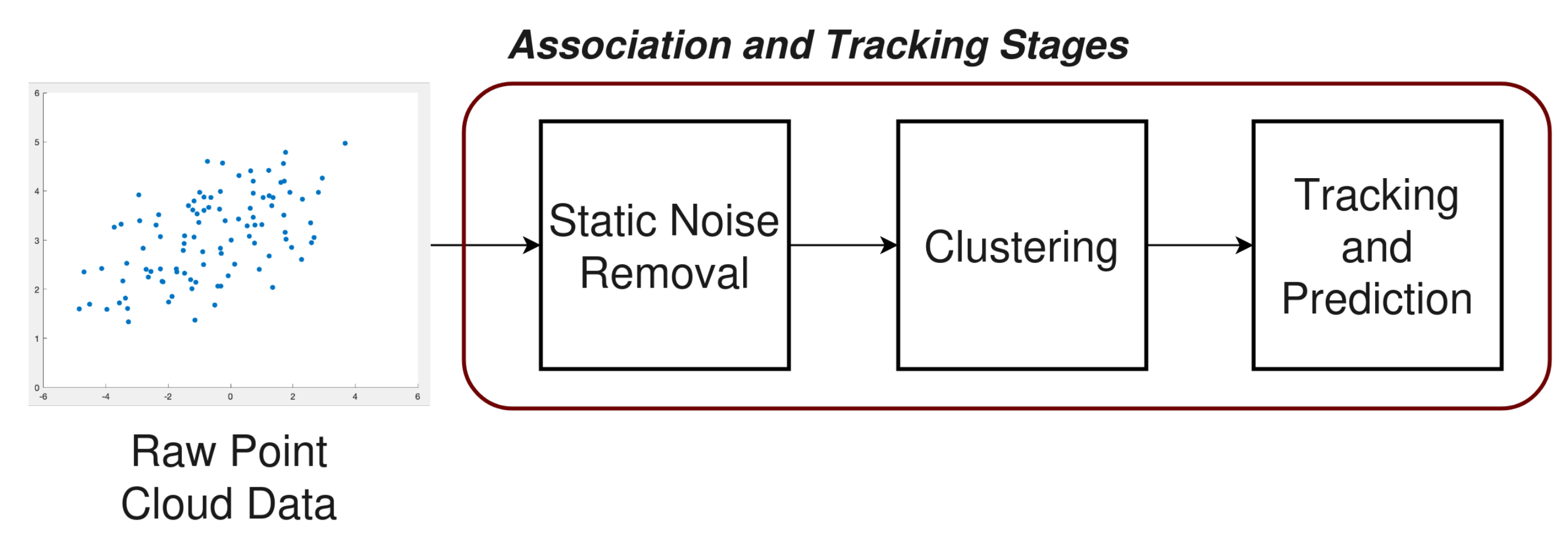
17], the radar point cloud clusters are formed using an approach similar to the typical architecture discussed in Section 2 of this paper, with DBSCAN. Similarly, the bounding boxes on the image plane are initially formed in isolation to the radar and then sent to the fusion-extended Kalman filter to be associated and tracked with the radar clusters. The plane of the camera data points is transformed from an image plane to a world plane using a homography estimation method [17]. A warped bird’s eye view of the camera data points can then be estimated using the world coordinates. The estimated warped bird’s eye view can then be compared and associated with the radar point cloud data points [17]. In the fusion-extended Kalman filter presented by [17], the error bounds are updated using data points from both of the sensors (as opposed to independently) and the warped bird’s eye view of the image plane is calculated for each sample point. As a result, the authors of [17] demonstrate that although this yields a higher association accuracy a time synchronization challenge is faced between the sensors. This challenge is resolved in the research by ensuring timeline alignment between the sensors and a synchronization strategy is employed by comparing certain regions of the fusion-extended Kalman filter output with the error bounds [17]. The experimental results presented by [17] appear to demonstrate a higher reliability in real-time target detection and persisted tracks, compared to a radar alone. Another approach seen in literature towards mmWave sensor fusion, is a track-to-track based association method. The authors of [18] demonstrate an implementation of track-to-track based association between a mmWave radar and a thermal camera. In the research presented by [18], it is assumed the independent sensors are co-located, whereby the two sensors are orientated and located is the same position. Under this operating condition, the targets in the field of view are tracked independently by the mmWave sensor and thermal camera. The independent tracks are then ultimately associated by solving a combinatorial cost minimization problem. In the research presented by [18], the components involved in this problem are identified as:
  • Estimated distance
  • Projected horizontal component
  • Track length
Exploiting micro-Doppler in mmWave radar systems is actively being sought as another angle to devise methodologies that resolve the challenge of static object detection and localization. Specifically in the context of human detection, bio-metric information, such as heartbeat and breathing are being explored as potential features that are measurable through micro-Doppler. A study performed by [19] demonstrates an algorithm designed to localize multiple static humans using their individual breathing pattern. The research performed by [19] highlight that the time of flight of a signal is minimally impacted by the small movements of a breathing chest cavity. As a result, the sub-millimeter movements are lost when performing static background removal between two consecutive frames, 12.5 ms apart in the case of the experiment performed by [19]. To counter this loss of information, the authors in [19] suggest subtracting the static background from a frame that is a few seconds apart, 2.5 s in the case of the research performed by [19]. In doing this, the sub-millimeter movements are ultimately exaggerated in comparison to a truly stationary object and therefore are left intact when preforming a removal of static data points.
The authors of [19] make note that removing static background points from a frame that is a few seconds apart does not work in for a non-stationary object, such as a person walking. This is due to the principle that the movements appear exaggerated when comparing to a frame a few seconds apart, so [19] notes that walking appears ‘smeared’ in this regard. Based on this differing outcome with static and dynamic objects, the algorithm presented in [19] employs independent different background removal strategies; one for static object using a long window and one for dynamic objects using a short window. The experimental results presented in [19] demonstrate a high accuracy of 95%. It should be noted that the experiments performed by [19] does not appear to quantify the success of both moving individuals and static individuals simultaneously within the scene. The radar architecture used in the research presented by [19] is slightly different to the mmWave tracking system that has been discussed in this paper. However, the research performed by [19] illustrates the potential to use vital signs as a means of detecting a static object. It would be of interest to assess the range potential of implementing a static localization algorithm of this nature using a mmWave tracking system architecture.
The literature explored in this paper regarding vision sensor fusion and bio-metric micro-Doppler feature analysis are viable approaches to enhance traditional object detection techniques to track objects interchanging from a dynamic and static movement state. Table 1 outlines the advantages and disadvantages of the two methodologies with respect to the comparison criteria. Although individually both methodologies prove viable, it would be interesting to consider a combination of both methodologies to compliment each other. Specifically, incorporating a micro-Doppler feature analysis component to the vision system could in turn remove the need of utilizing the universal background subtraction algorithm [20] for identifying moving objects in the image. This could potentially be considered as a three component sensor fusion approach, where camera data points, static radar data points and dynamic radar points are fused.

3.2. Sensing Methodologies

Sensing is not typically considered a usual aspect that is present in an object tracking system. However, it is a stream of research that has been investigated independently and has the potential when integrated with a tracking system to enhance the tracking systems sensitivity and reliability. An enhancement to the tracking system through sensing could ultimately spawn through the additional extracted features that the sensing solution provides, granting more data points that can be incorporated into the tracking estimation and prediction. The advanced sensing methodologies that are explored in this paper can be classified as either general activity recognition or specialized estimation methodologies.
General activity recognition can be considered as a class of sensing methodologies that have an underlying objective of classifying a broad set of movements or activities that a given object in the field of view might exhibit. One stream of research that dominates this class of sensing methodologies is human activity recognition (HAR). Traditionally, a radar based HAR system relied on machine learning techniques such as random forest classifiers [21], dynamic time warping [22] and support vector machines (SVM) [23]. In comparison to a deep learning based approach, these techniques are usually computationally less taxing due to their lower complexity. However, relying solely on conventional machine learning techniques for HAR contrastingly presents several limitations. A survey conducted by the authors of [24] provides a thorough critical analysis over the evolution of radar-based HAR. In [24], a conventional machine learning approach to HAR is considered to make optimization and generalization of the HAR solution difficult. The authors of [24] highlight three fundamental limitations of machine learning techniques with respect to a HAR system. The first acknowledges the approach in which feature extraction takes place, specifically a manual procedure based on heuristics and domain knowledge which is ultimately subject to the human’s experience [24]. The second limitation identified relates to the fact that manually selected features tend to also be accompanied by specific statistical algorithms that are dependent on the trained dataset. As a result, when applying the trained model to a new dataset the performance is typically not as good as the dataset that was used to train the model. Lastly, the authors of [24] highlighted that the conventional machine learning approaches used in a radar based HAR system primarily learn on discrete static data. This poses a difference between the data that are used to train a model and the data that the model is subject to during real-time testing. The real-time data are principally continuous and dynamic in nature. The survey conducted by [24] explores the potential for deep learning to assist in alleviating these limitations in machine learning radar-based HAR systems.
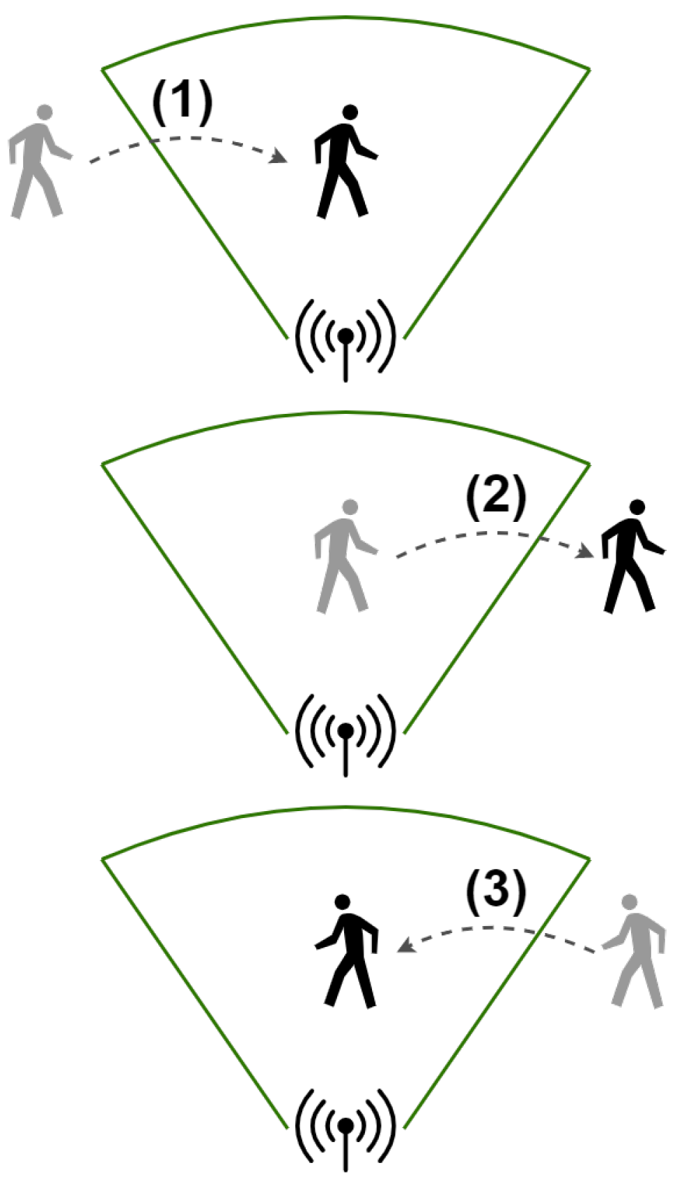
Although there are some limitations with using conventional machine learning approaches, it should also be acknowledged that there has been successful applications of radar-based HAR using these techniques. The research presented in [25] identifies recent work that attempts to classify three different walking/movement patterns:
  • Slow walk
  • Fast walk
  • Slow walk with hands in pockets
The authors of [
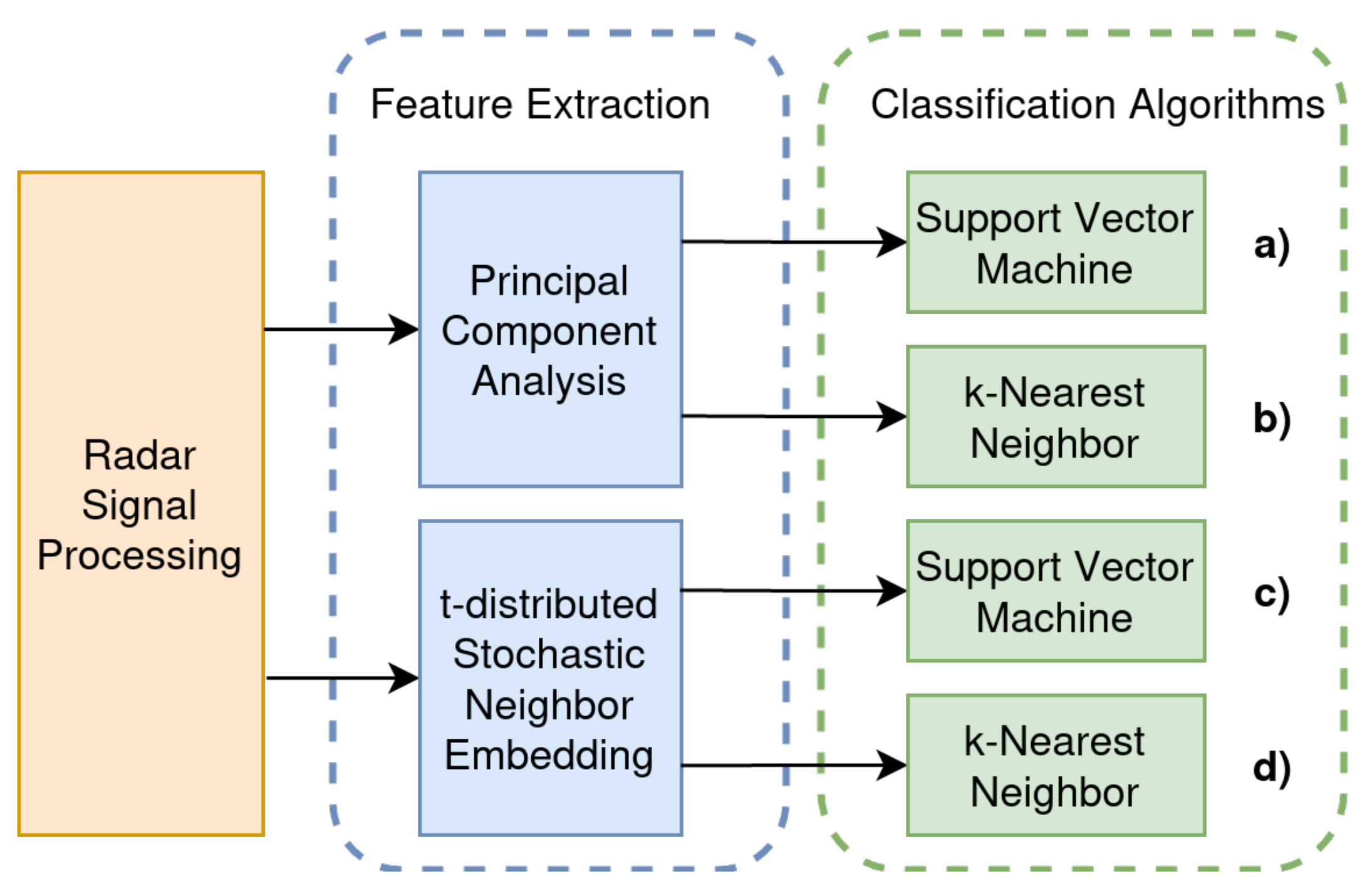
25] attempt to classify these walking patterns comparing the performance between an approach using k-Nearest Neighbor (k-NN) and SVMs. The four system designs explored in the work presented by [25] can be seen illustrated in Figure 7. In [25], both the range-Doppler and Doppler-time data are incorporated into feature extraction. In the research presented by [25], the impact each of the walking patterns has in the range-Doppler and Doppler-time maps is illustrated in the form of a heat-map. It can be seen in this illustration, that the change in walking speed (the difference between slow and fast walking) results in a dramatic change in the range-Doppler and Doppler-time maps. Whereas, maintaining a consistent walking speed and with hands in the pocket has less of a notable difference.
In regard to extracting the features, the authors of [25] explore and compare two potential approaches, using either Principle Component Analysis or t-distributed Stochastic Neighbor Embedding. Both of which are non-supervised transform algorithms. The two feature extraction methods are compared against each other whilst equally being applied with the two aforementioned classification methods. The permutations of feature extraction methods with classification algorithms explored are shown in Figure 7. The results obtained from [25] for each of the explored system designs in Figure 7 demonstrate the capability of classifying fast and slow walking with high accuracy. Using the feature extraction methods and classification algorithms explored in [25], the authors note a 72% accuracy in classifying slow walking with hand in the pocket.
Another piece of leading research in radar-base HAR is RadHAR presented in [26]. In [26], the authors explore a range of classification approaches, including both conventional machine learning algorithms and deep learning based algorithms. The primary objective of the RadHAR system is to classify five human movement activities; walking, jumping, jumping jacks, squats and boxing.
Unlike the research presented in [25], in [26] the data that are used for classification originates from point cloud. The point cloud data are first voxelized to to ensure a uniform frame size, despite the number of points, before feeding to the classification algorithm. Using the voxelized point cloud data, an SVM, multi-layered perceptron (MLP), Long Short-term Memory (LSTM) and convolution neural network (CNN) combined with LSTM were trained and compared against each other.
The results of the research conducted in [26] demonstrate that the classification algorithm with the highest accuracy, 90.47%, is that of a combined time-distributed CNN and bi-directional LSTM. The authors of [26] hypothesis that the high accuracy of this approach can be attributed towards the fact that the time-distributed CNN learns the spatial features of the point cloud data, whilst the bi-directional LSTM learns the time dependent component of the activities being performed.
Another more recent piece of research, presented in [27], demonstrates a mmWave sensing framework that is capable of recognizing gestures fundamentally using micro-Doppler and AoA (both elevation and azimuth) data to form a set of feature maps. Features are then ultimately extracted using an empirical feature extraction method and used to train a MLP to classify gestures [27]. An important aspect to consider regarding the research presented by the authors of [27], is that the approach presented is for a field of view where only a single human performing gestures is present (i.e., not multi-object). This same limitation can also be seen in a similar piece of research presented in [28]. The authors of [28] demonstrate a mmWave system capable of performing 3D finger joint tracking using the vibrations and distortions evident on the forearm as a consequence to finger movements. However, as previously mentioned, this specialized estimation is also subject to the challenge of operating in a multi-person environment. Despite this, the authors of [27] have made their approach so that underlying encoded assumptions about the number of people in the field of view has been abstracted from the core methodology to performing gesture recognition. Instead, the field of view constraint has been isolated to being a data formation challenge. The authors of [27] acknowledge that the range data have not been taken into account in their presented approach, but would yield beneficial in extending their design to handle multiple people simultaneously performing their own sequence of gestures. Putting the specific classification task aside, the abstracted methodology presented by the authors of [27] could serve as a framework to incorporating generalized activity recognition into a mmWave multi-object tracking system, ultimately uplifting the tracking profile maintained for an individual. As the authors of [27] did not have multi-object within scope, extending the methodology to operate on each range bin, for satisfying multi-object support, raises concerns around whether real-time processing is still feasible.
Specialized estimation, as opposed to general activity recognition, is a class of sensing that ultimately has a primary focus on a single objective that can be measured. Measurement of this nature of course should be considered as an estimation. This class of sensing has overlap with features that can be used as a criteria for identifying a specific object. More details on features with the potential to be used as an identification strategy are addressed in Section 3.3 of this paper. The primary driver behind research in radar-based specialized estimation methodologies originates from a human health perspective. The ability to determine human vital signs passively is an area in which mmWave radar is being explored as a viable solution. A study performed in [29] demonstrates a solution named ’mBeats’ which aims to implement a moving mmWave radar system that is capable of measuring the heartbeat of an individual. The proposed ’mBeats’ system implements a three module architecture. The first modules is a user tracking module, which the authors of [29] state that the system utilizes a standard point cloud based tracking system, as illustrated in Section 2 of this paper. The purpose of this module is to ultimately find the target in the room. It should be noted that in [29] an assumption is made that there will only be one target in the field of view. The second module is termed proposed in [29] is termed as the ‘mmWave Servoing’ module. The purpose of this module is to optimize the angle in which the target is situated from the mmWave radar to give the best heartbeat measurement. To achieve this, the authors of [29] specify the ultimate goal of this module as obtaining peak signal reflections for the targets lower limbs, since the mmWave radar is situated on a robot at ground level. Using the Peak To Average value as a determinant for the reflected signal strength, the authors define an observation variable which is incorporated by a feedback Proportional-Derivative controller to ultimately orientate the radar in the direction that yields the highest signal strength.
The last module is the heart rate estimation module, responsible for ultimately determining the targets heart rate from a set of different poses. The poses consist of various sitting and lying down positions. The authors of [29] acknowledge that heartbeats lie in the frequency band of 0.8∼4 Hz, and therefore implement a biquad cascade infinite impulse response (IIR) filter to eliminate unwanted frequencies and extract the heartbeat waveform. A CNN is selected in [29] as the predictor due to the heartbeat detection problem being considered as a regression problem. The authors state that a key challenge with using a CNN for this problem is estimating the uncertainty of the result. Uncertainty in this problem is ultimate caused by measurement inaccuracies, sensor biases and noise, environment changes, multipath and inadequate reflections [29]. To overcome this, the authors of [29] cast the problem into a Bayesian model, defining the likelihood between the prediction and ground truth ( y ) as a probability following a Gaussian distribution. This ultimately results in a loss function as illustrated in Equation (11).
l o s s ( x ) = y y ^ 2 2 σ 2 + 1 2 log σ 2
where the CNN predicts a mean y ^ and variance σ 2 . Using this approach the authors of [29] compare the outcome of their model with three other common signal processing approaches (FFT, Peak Count (PK) and Auto-correlation (XCORR)) with accuracy as the metric that is compared.
In the results presented in [29], it can be seen that the other approaches fail to maintain an accuracy above 90% in all poses, whereas the CNN presented in [29] does maintain a high accuracy for the selected poses. The authors acknowledge that in the current system the target must maintain static whilst performing the heartbeat measurement and that future work will be focused on measuring a moving object. It would also be interesting to assess the viability and challenges of this approach in a multi-person scene.
The underlying theme of the sensing methodologies explored in this paper is that independently they are successful in the goal they aim to achieve. However, there is a lack of acknowledgment in the literature regarding the suitability of these methodologies in a combined holistic tracking and sensing architecture. It would not only be interesting to assess their suitability in such a system, but also how they may contribute to enhance the sophistication and reliability of such a tracking system. Table 2 outlines the advantages and disadvantages of the explored sensing methodologies, with respect to the comparison criteria. It can be seen in this table that both methodologies explored fail to address the challenges of operating in a multi-object environment. In order to achieve a tracking system that completes a target profile with sensing characteristics, the challenge of sensing multiple objects and associating the acquired information to a detected target must be solved.

3.3. Identification Strategies

The development of identification methodologies is a natural direction of the evolution for mmWave tracking systems. It can be considered a more unique type of specialized estimation sensing but with the key focus on being able to reliably and uniquely correlate the sensed information to a tracked object. There are a number of challenges that need to be considered and overcome in identification approaches, such as the feasible range, separation of multiple objects/people and generalization of the approach. This sections aims to explore the leading identification methodologies of radar-based tracking systems.
Gait identification approaches rely on the different gait characteristics between individuals. Gait based identification strategies are the most common passive based approach to identifying people in a radar or WiFi based tracking system. They fundamentally leverage that each person typically has a unique pattern in the way they walk, this pattern is most often identified through a deep learning-based technique. Gait recognition can pose its own challenges, such as inconsistencies and unpredictable upper limb movements that influence the lower limb signal reflections. This interference can ultimately reduce the reliability of obtaining a consistent lower limb gait pattern for a given individual. A recent study performed in [30] attempts to overcome the challenges associated with upper limb movement interference by narrowing the vertical field of view and focusing attention on the finer grain movements of the lower limbs. The research presented in [30] proposes a system that comprises of three phases:
  • Signal processing and feature extraction
  • Multi-user identification
  • CNN-based gait model training
In the first phase the authors of [30] construct a range-Doppler map following the traditional methodology described in Section 2 of this paper. The stationary interference in the range-Doppler map is then removed following a technique similar to the described approach in Section 2.3 of this paper. The stationary reflections are subtracted from each frame of the range-Doppler frequency responses. The authors of [30] observe that a cumulative deviation of the range-Doppler data occurs due to the dynamic background noises, which are not eliminated when subtracting the static interference. To overcome this, a threshold-based high-pass filter is implemented with a threshold τ of 10 dBFS. This filter is described in Equation (12).
R ( i , j , k ) = R ( i , j , k ) , R ( i , j , k ) τ , 0 , R ( i , j , k ) < τ ,
where R ( i , j , k ) is the range-Doppler domain frequency response at the k t h frame with range i and velocity j.
The authors of [30] identify that the dominant velocity V ^ i can be used to describe the targets lower limb velocity in each frame. In [30], this is expressed as Equation (13).
V ^ i = j = 1 N D R ^ ( i , j , k ) V j N D , i 1 , N R , j 1 , N D .
where R ^ ( i , j , k ) is the normalized frequency response, V j is the velocity corresponding to the frequency response R ( i , j , k ) , N R and N D represent the number of range-FFT and Doppler-FFT points respectively.
The authors of [30] illustrate the composition of these gait characteristics as a heat-map corresponding to the actual gait captured with a camera. Using these extracted gait features, the author of [30] identifies that multiple targets can be differentiated firstly by range and secondly (if the range is the same) by leveraging distinct spatial positions. This is ultimately done by projecting the point R ( i , j , k ) in the k t h frame to a point R ^ ( i , j , k ) in the two-dimensional spatial Cartesian coordinate system. To differentiate the data points in the spatial Cartesian coordinate system, Ref. [30] implements a K-means clustering algorithm. Each individual gait feature can be generated as a range-Doppler map by negating the frequency responses that were not correlated in the K-means clustering [30]. After differentiating the gait features, the authors of [30] then identify a challenge regarding the segmentation of the actual step. In [30], this is ultimately overcome by using an unsupervised learning technique to detect the silhouette of the steps.
Finally, a CNN-based classifier in the image recognition domain is used to identify the patterns associated with the gait feature maps. The classifier is assessed with multiple users and varying steps to determine the overall accuracy of the system. Overall, the system demonstrates a high accuracy that marginally decreases in accuracy as the number of users increases but is ultimately corrected as the number of steps increases.
Another overarching class of identification strategies being explored are tagging based approaches. This is not a passive approach unlike the others mentioned in this paper and involves incorporating a tag on the object so that it can be uniquely identified. There are two directions in which the literature focuses on in regards to identification of this nature. The first is radio frequency identification (RFID). In a chipless based RFID system, data must be encoded in the signal either by altering the time-domain, frequency-domain, spatial-domain or a combination of two or more of the domains. An example of RFID implemented as an identification strategy in mmWave can be seen in the ‘FerroTag’ research presented in [31]. The ‘FerroTag’ system presented in [31] is a paper-based RFID system. Although the usage of the FerroTag research is intended for inventory management, it could potentially be adopted to as a tagging strategy for a tracking based system. FerroTag is ultimately based on ferrofluidic ink, which is colloidal liquids that fundamentally contain magnetic nanoparticles. The ferrofluidic ink can be printed onto surfaces which in turn will embed frequency characteristics in the response of a signal. The shape, arrangement and size of the printed ferrofluidic ink will ultimately influence the frequency tones that are applied to the response signal. In order to identify and differentiate the different signal characteristics caused by the chipless RFID surface, the solution presented by [31] utilizes a random forest as a classifier to identify the corresponding tags present in the field of view. The second approach to tagging as a means of identification is through re-configurable reflective surfaces (RIS). To the best of our knowledge no system has been presented in the literature that demonstrates a practical RIS solution for identification purposes in a mmWave tracking system. Research regarding RIS with respect to mmWave is predominantly in the communication domain. The challenges and opportunity to design an RIS based identification system for a mmWave tracking system are yet to be detailed.
Shape profiling has been seen implemented in previous mmWave research to identify an object by the properties of the objects shape. For example, if the object being tracked is a human, the height and curvature of the human body can influence the way in which the mmWave signal is reflected [32]. The authors of [32] demonstrate how a human being tracked and represented in point cloud form can be identified based on the shape profile of their body. Using a fixed-size tracking window, the related points to the particular human are voxelized to form an occupancy grid [32]. This is then ultimately sequenced through a Long-short Term Memory network to classify the particular human [32]. This particular identification method is abstracted from the tracking aspect of the process, therefore making it suitable regardless if there are multiple objects being tracked. suitable for identifying objects in an environment where multiple object tracking is taking place.
The research presented in [33] differs to that presented in [32] in the regard that the tracking data are not used during the identification stage. Instead, the authors in [33] propose a strategy where once the human has been tracked, the radar adjusts its transmit and receive beams towards the tracked human. By doing so the granularity of the feature set available from the human body is increased. In other words, more specific profiling can be performed on the individual. The research presented in [33] demonstrates the ability to characterize the human body by its outline, surface boundary and vital signs. Having this granular feature set, and tailored profiling, provides a stronger ground to positively identify an individual. However, this particular method does come at the cost of directing the beam just for identification purposes. Additionally, the existing research presented in [33] does not make any remarks regarding the suitability for this method in real-time applications.
The various identification strategies explored in this section of the paper each have their own complexities involved in fundamentally incorporating into a tracking system. Table 3 aims to assist in comparing the various identification methodologies, to ultimately understand their suitability and limitations around implementing them in a tracking system.

4. Future Research Directions

Despite many advancements underway in achieving a unified mmWave tracking and sensing architecture, there are still many challenges and limitations to be resolved. The following are suggestions for some of the key areas in which future research should be directed to assist in the development of the limitations associated with such a unified system:
  • Concurrent Tracking Enhancements: The number of people that can reliably be concurrently tracked continues to be a challenge for a tracking system. It would be of interest to explore potential areas that could provide a scalable approach to this problem. Integrating sensing outcomes into the tracking estimation and prediction filter could be an area that is worth exploring to assist with overcoming tracking concurrency challenges.
  • Coverage Area: The maximum range in which a solution is functional until can impact the practicality of the solution. This is specifically true for systems that are dependent of high signal resolution, therefore sacrificing range. The default approach to this problem is to simply increase the transmitter power. However, in situations where this might not be possible it would be beneficial to research novel approaches that overcome signal range without increasing the transmitter power and minimally impacting the resolution. It could prove beneficial to investigate the techniques being employed using RIS in the communications domain for signal propagation and beam steering as a potential to be smarter with obtaining a larger coverage area.
  • Integrating Tracking and Sensing Systems: There are currently not many integrated sensing and tracking mmWave systems present in the literature. The challenges and limitations that come with doing so deserve more focus. Integrating systems of this nature could prove fruitful in designing an enhanced tracking system capable of discontinuous tracking and more robust predictions.
  • Real-time Performance: As the techniques for advanced tracking systems evolve and become more complex, their feasibility for real-time applications requires assessment. This especially becomes true when incorporating sensing solutions reliant on deep learning-based algorithms.
  • Stationary Object Tracking: Lastly, in a pure tracking system a large fundamental floor is the method in which static noise is removed from the signal response. The traditional approach of subtracting signal responses that do not change between frames immediately scarifies stationary objects that should not be considered as noise, such as a person sitting. This challenge could be researched by either exploring more sophisticated static noise removal techniques or by attempting to recover stationary objects of interest after the removal of static signal responses.
  • RNN Suitability In the literature there is an underlying theme of CNN models being utilized and demonstrating the best performance. This is in contrary to the theoretical better suitability of recurrent neural network (RNN) models for temporal based data. A likely reason for their lack of use could be attributed toward the difficulty of training the shared parameters across the layers. It would be interesting to look at introducing an algorithm unfolding technique to address this potential issue by embedding domain knowledge into the network itself.

5. Conclusions

This paper aimed to provide an overview and analysis into traditional, state-of-the-art, and future methodologies for mmWave multi-object tracking. In the review of the advanced methodologies it should be noted that many of the approaches explored have only been implemented in an isolated setting. They demonstrate their potential and success in achieving the particular purpose they were intended for. However, the challenges and limitations involved in incorporating some of these advanced methodologies into a real-time tracking system are yet to be further explored.

Author Contributions

Methodology, A.P. and J.A.Z.; resources, R.X. and K.W.; writing—original draft preparation, A.P. and J.A.Z.; writing—review and editing, R.X. and K.W. All authors have read and agreed to the published version of the manuscript.

Funding

This research is partially funded by the Australian Research Council under the Discovery Project Grant DP210101411.

Institutional Review Board Statement

Not applicable.

Informed Consent Statement

Not applicable.

Conflicts of Interest

The authors declare no conflict of interest.

Abbreviations

The following abbreviations are used in this manuscript:
AoAAngle of Arrival
CNNConvolutional Neural Network
DBSCANDensity-based Spatial Clustering of Applications with Noise
FFTFast Fourier Transformation
FMCWFrequency-modulated Continuous-wave
HARHuman Activity Recognition
IFIntermediate Frequency
IIRInfinite Impulse Response
IR-UWBImpulse Radio Ultra-wide Band
k-NNK-Nearest Neighbor
LSTMLong Short Term Memory
MIMOMultiple-input Multiple-output
MLPMulti-layered Perceptron
mmwaveMillimeter Wave
PKPeak Count
RFIDRadio Frequency Identification
RISRe-configurable Reflective Surfaces
RNNRecurrent Neural Network
RXReceive
SVMSupport Vector Machines
TITexas Instruments
TXTransmit
XCORRAuto-correlation

References

  1. Björklund, S.; Johansson, T.; Petersson, H. Evaluation of a micro-Doppler classification method on mm-wave data. In Proceedings of the 2012 IEEE Radar Conference, Atlanta, GA, USA, 7–11 May 2012; pp. 934–939. [Google Scholar]
  2. Chiani, M.; Giorgetti, A.; Paolini, E. Sensor Radar for Object Tracking. Proc. IEEE 2018, 106, 1022–1041. [Google Scholar] [CrossRef] [Green Version]
  3. Choi, J.W.; Nam, S.S.; Cho, S.H. Multi-Human Detection Algorithm Based on an Impulse Radio Ultra-Wideband Radar System. IEEE Access 2016, 4, 10300–10309. [Google Scholar] [CrossRef]
  4. Hantscher, S.; Hägelen, M.; Lang, S.; Schlenther, B.; Essen, H.; Tessmann, A. Localisation of concealed worn items using a millimeter wave FMCW radar. In Proceedings of the Asia-Pacific Microwave Conference 2011, Melbourne, VIC, Australia, 5–8 December 2011; pp. 955–958. [Google Scholar]
  5. Zeng, J.; Dong, Z. Some MIMO radar advantages over phased array radar. In Proceedings of the 2nd International Conference on Industrial Mechatronics and Automation, Wuhan, China, 30–31 May 2010; Volume 2, pp. 211–213. [Google Scholar] [CrossRef]
  6. Fishler, E.; Haimovich, A.; Blum, R.S.; Cimini, L.J.; Chizhik, D.; Valenzuela, R.A. Spatial Diversity in Radars—Models and Detection Performance. IEEE Trans. Signal Process. 2006, 54, 823–838. [Google Scholar] [CrossRef]
  7. Bekkerman, I.; Tabrikian, J. Target Detection and Localization Using MIMO Radars and Sonars. IEEE Trans. Signal Process. 2006, 54, 3873–3883. [Google Scholar] [CrossRef]
  8. Rohling, H.; Kronauge, M. New radar waveform based on a chirp sequence. In Proceedings of the 2014 International Radar Conference, Lille, France, 13–17 October 2014; pp. 1–4. [Google Scholar] [CrossRef]
  9. Ester, M.; Kriegel, H.P.; Sander, J.; Xu, X. A Density-Based Algorithm for Discovering Clusters in Large Spatial Databases with Noise. In Proceedings of the Second International Conference on Knowledge Discovery and Data Mining, KDD’96, Portland, OR, USA, 2–4 August 1996; AAAI Press: Washington, DC, USA, 1996; pp. 226–231. [Google Scholar]
  10. Kellner, D.; Klappstein, J.; Dietmayer, K. Grid-based DBSCAN for clustering extended objects in radar data. In Proceedings of the 2012 IEEE Intelligent Vehicles Symposium, Madrid, Spain, 3–7 June 2012; pp. 365–370. [Google Scholar] [CrossRef]
  11. Wagner, T.; Feger, R.; Stelzer, A. Modification of DBSCAN and application to range/Doppler/DoA measurements for pedestrian recognition with an automotive radar system. In Proceedings of the 2015 European Radar Conference (EuRAD), Paris, France, 9–11 September 2015; pp. 269–272. [Google Scholar] [CrossRef]
  12. Schubert, E.; Meinl, F.; Kunert, M.; Menzel, W. Clustering of High Resolution Automotive Radar Detections and Subsequent Feature Extraction for Classification of Road Users. In Proceedings of the 2015 16th International Radar Symposium (IRS), Dresden, Germany, 24–26 June 2015. [Google Scholar] [CrossRef]
  13. Schlichenmaier, J.; Roos, F.; Kunert, M.; Waldschmidt, C. Adaptive clustering for contour estimation of vehicles for high-resolution radar. In Proceedings of the 2016 IEEE MTT-S International Conference on Microwaves for Intelligent Mobility (ICMIM), San Diego, CA, USA, 19–20 May 2016; pp. 1–4. [Google Scholar] [CrossRef]
  14. Julier, S.J.; Uhlmann, J.K. New extension of the Kalman filter to nonlinear systems. In Proceedings of the Signal Processing, Sensor Fusion, and Target Recognition VI, Orlando, FL, USA, 21–25 April 1997; Kadar, I., Ed.; International Society for Optics and Photonics, SPIE: Bellingham, WA, USA, 1997; Volume 3068, pp. 182–193. [Google Scholar] [CrossRef]
  15. Ikram, M.Z.; Ali, M. 3-D object tracking in millimeter-wave radar for advanced driver assistance systems. In Proceedings of the 2013 IEEE Global Conference on Signal and Information Processing, Austin, TX, USA, 3–5 December 2013; pp. 723–726. [Google Scholar]
  16. Tian, X.; Wang, Z.; Chang, T.; Cui, H.L. Adaptive Background Clutter Mitigation for Millimeter Wave MIMO Imaging. IEEE Trans. Geosci. Remote. Sens. 2022, 60, 4701216. [Google Scholar] [CrossRef]
  17. Zhang, R.; Cao, S. Extending Reliability of mmWave Radar Tracking and Detection via Fusion with Camera. IEEE Access 2019, 7, 137065–137079. [Google Scholar] [CrossRef]
  18. Canil, M.; Pegoraro, J.; Rossi, M. milliTRACE-IR: Contact Tracing and Temperature Screening via mmWave and Infrared Sensing. IEEE J. Sel. Top. Signal Process. 2022, 16, 208–223. [Google Scholar] [CrossRef]
  19. Adib, F.; Kabelac, Z.; Katabi, D. Multi-Person Localization via RF Body Reflections. In Proceedings of the 12th USENIX Symposium on Networked Systems Design and Implementation (NSDI 15), Oakland, CA, USA, 4–6 May 2015; USENIX Association: Oakland, CA, USA, 2015; pp. 279–292. [Google Scholar]
  20. Barnich, O.; Droogenbroeck, M. ViBe: A Universal Background Subtraction Algorithm for Video Sequences. Image Process. IEEE Trans. 2011, 20, 1709–1724. [Google Scholar] [CrossRef] [PubMed] [Green Version]
  21. Smith, K.A.; Csech, C.; Murdoch, D.; Shaker, G. Gesture Recognition Using mm-Wave Sensor for Human-Car Interface. IEEE Sens. Lett. 2018, 2, 3500904. [Google Scholar] [CrossRef]
  22. Zhou, Z.; Cao, Z.; Pi, Y. Dynamic Gesture Recognition with a Terahertz Radar Based on Range Profile Sequences and Doppler Signatures. Sensors 2017, 18, 10. [Google Scholar] [CrossRef] [PubMed] [Green Version]
  23. Kim, Y.; Ling, H. Human Activity Classification Based on Micro-Doppler Signatures Using a Support Vector Machine. IEEE Trans. Geosci. Remote. Sens. 2009, 47, 1328–1337. [Google Scholar] [CrossRef]
  24. Li, X.; He, Y.; Jing, X. A Survey of Deep Learning-Based Human Activity Recognition in Radar. Remote. Sens. 2019, 11, 1068. [Google Scholar] [CrossRef] [Green Version]
  25. Senigagliesi, L.; Ciattaglia, G.; De santis, A.; Gambi, E. People Walking Classification Using Automotive Radar. Electronics 2020, 9, 588. [Google Scholar] [CrossRef]
  26. Singh, A.; Sandha, S.; Garcia, L.; Srivastava, M. RadHAR: Human Activity Recognition from Point Clouds Generated through a Millimeter-wave Radar. In Proceedings of the MobiCom’19: The 25th Annual International Conference on Mobile Computing and Networking, Los Cabos, Mexico, 25 October 2019; pp. 51–56. [Google Scholar] [CrossRef]
  27. Ninos, A.; Hasch, J.; Zwick, T. Real-Time Macro Gesture Recognition Using Efficient Empirical Feature Extraction With Millimeter-Wave Technology. IEEE Sens. J. 2021, 21, 15161–15170. [Google Scholar] [CrossRef]
  28. Liu, Y.; Zhang, S.; Gowda, M.; Nelakuditi, S. Leveraging the Properties of MmWave Signals for 3D Finger Motion Tracking for Interactive IoT Applications. Proc. ACM Meas. Anal. Comput. Syst. 2022, 6, 1–28. [Google Scholar] [CrossRef]
  29. Zhao, P.; Lu, C.X.; Wang, B.; Chen, C.; Xie, L.; Wang, M.; Trigoni, N.; Markham, A. Heart Rate Sensing with a Robot Mounted mmWave Radar. In Proceedings of the 2020 IEEE International Conference on Robotics and Automation (ICRA), Paris, France, 31 May–31 August 2020; pp. 2812–2818. [Google Scholar] [CrossRef]
  30. Yang, X.; Liu, J.; Chen, Y.; Guo, X.; Xie, Y. MU-ID: Multi-user Identification Through Gaits Using Millimeter Wave Radios. In Proceedings of the IEEE INFOCOM 2020—IEEE Conference on Computer Communications, Toronto, ON, Canada, 6–9 July 2020; pp. 2589–2598. [Google Scholar] [CrossRef]
  31. Li, Z.; Chen, B.; Yang, Z.; Li, H.; Xu, C.; Chen, X.; Wang, K.; Xu, W. FerroTag: A Paper-Based MmWave-Scannable Tagging Infrastructure. In Proceedings of the 17th Conference on Embedded Networked Sensor Systems, SenSys ’19, New York, NY, USA, 10–13 November 2019; Association for Computing Machinery: New York, NY, USA, 2019; pp. 324–337. [Google Scholar] [CrossRef]
  32. Zhao, P.; Lu, C.X.; Wang, J.; Chen, C.; Wang, W.; Trigoni, N.; Markham, A. mID: Tracking and Identifying People with Millimeter Wave Radar. In Proceedings of the 2019 15th International Conference on Distributed Computing in Sensor Systems (DCOSS), Santorini, Greece, 29–31 May 2019; pp. 33–40. [Google Scholar]
  33. Gu, T.; Fang, Z.; Yang, Z.; Hu, P.; Mohapatra, P. MmSense: Multi-Person Detection and Identification via MmWave Sensing. In Proceedings of the 3rd ACM Workshop on Millimeter-Wave Networks and Sensing Systems, mmNets’19, Los Cabos, Mexico, 25 October 2019; Association for Computing Machinery: New York, NY, USA, 2019; pp. 45–50. [Google Scholar] [CrossRef]
Figure 2. mmWave tracking architecture block diagram.
Electronics 12 00308 g002
Figure 3. Signal chirp components. An example chirp, where the frequency is represented over time to ultimately demonstrate sweep bandwidth and frequency slope.
Electronics 12 00308 g003
Figure 4. Typical FMCW radar system.
Electronics 12 00308 g004
Figure 5. Generalized stages of association and tracking in a mmWave tracking architecture system.
Electronics 12 00308 g005
Figure 6. Areas explored and discussed in Section 3 in contrast to the typical multi-object mmWave tracking architecture block diagram presented in Figure 2.
Electronics 12 00308 g006
Figure 7. Walking classification system designs explored in [25]; (a) Principal component analysis combined with support vector machine classification; (b) Principal component analysis combined with k-nearest neighbor classification; (c) t-distributed stochastic neighbor embedding combined with support vector machine classification; (d) t-distributed stochastic neighbor embedding combined with k-nearest neighbor classification.
Electronics 12 00308 g007
Table 1. A comparison of methodologies explored for the enhancement of object detection in a mmWave tracking architecture.
Crit.mmWave and Vision Sensor FusionMicro-Doppler Feature Analysis
Adap.
Low architecture assumptions.
Unified sensor point cloud data.
×
Unified plane projection overhead.
Decoupled from architecture dependencies.
×
Specialized noise treatment.
Perf.
Suitability demonstrated in the literature.
×
Potential time synchronization drift.
No impact to typical multi-object detection.
×
Immature understanding on technique overhead.
Accu.
Azimuth angle accuracy improved.
Multi-object track persistence improved.
×
Immature system understanding regarding the compromise of a single sensor (i.e., dark room).
High for multiple dynamic objects.
Uncompromised fixed multi-object tracking.
×
Immature understanding regarding accuracy and range relationship.
Spec.
All moving objects have a presence in radar and vision that can be correlated.
×
Fixed objects of interest are not typically distinguishable.
Technique not constrained to breathing.
×
Immature understanding of simultaneous static and fixed multi-object tracking.
Table 2. A comparison of sensing methodologies explored for the enhancement of tracking reliability in a mmWave tracking architecture.
Crit.Generalized Activity RecognitionSpecialized Estimation
Adap.
Decoupled architecture impact.
×
Uncertain tracking enhancement reliability.
Trusted point cloud processing techniques.
×
Uncertain feedback enhancement reliability.
Perf.
Algorithm real-time performance proven.
×
Uncertain system suitability.
Real-time suitability has been proven viable.
×
Optimization overhead to accommodate.
Accu.
High pre-defined activity accuracy.
×
Dependent on training environment.
High due to the narrow focus.
×
Highly coupled to the training data.
Spec.
Pre-defined actions reliably classified.
×
Uncertainty of multi-object suitability.
×
Simultaneous classification challenging.
Optimized for estimating a single action.
×
One target is considered for estimation.
×
Immature literature in mmWave field.
Table 3. A comparison of identification methodologies explored for the enhancement of tracking objects discontinuously in a mmWave tracking architecture.
Crit.GaitTaggingShape Profile
Adap.
Low architecture impact.
×
Ability to correlate to multiple tracks unknown.
×
Specific hardware positioning.
Loosley coupled to tracking architecture.
×
Different data domain.
×
Additional hardware.
×
Multi-object correlation challenge.
Potential to extend on point cloud.
×
Sampling concerns with simultaneous beam directing and tracking.
Perf.
Proven real-time viability.
×
Compute overhead.
Very minimal impact.
Pre-encoded data absorbs impact.
×
Untested multi-object setting.
Minimal overhead.
×
Suitability unproven.
Accu.
High multi-object accuracy.
×
Scalability challenges.
Very accurate.
×
Immature understanding on range.
No impact due to multi-object.
×
External dependencies.
Spec.
Focused movement considerations.
×
Challenges with wider field of view.
Low risk of false positives.
×
Undefined challenges with multi-object.
Multi-objects independently profiled.
×
Immature understanding on environmental impacts.
Disclaimer/Publisher’s Note: The statements, opinions and data contained in all publications are solely those of the individual author(s) and contributor(s) and not of MDPI and/or the editor(s). MDPI and/or the editor(s) disclaim responsibility for any injury to people or property resulting from any ideas, methods, instructions or products referred to in the content.

