
Review of Crucial Problems of Underwater Wireless Power Transmission

Abstract
:1. Introduction
- (1)
- What is the effect of highly conductive water dielectrics on the electrical parameters of WPT systems? What is the effect on the coil radiation resistance?
- (2)
- Underwater WPT systems are susceptible to current disturbances, extreme temperature and pressure conditions. What is the electromagnetic coupling structure required for underwater applications?
- (3)
- The fluctuation of the coupler gap distance caused by the actual underwater environment has an impact on the stability of the transmission efficiency, so how to achieve maximum power and efficiency tracking?
2. Underwater Wireless Power Transmission Technology and Principle
2.1. Classification Definition
- Magnetic field technology. Based on the principle of electromagnetic induction coupling, it is a wireless power transmission technology that realizes the wireless transmission of electric energy through the non-contact mode between power acquisition equipment and power supply by integrating modern power electronic energy conversion technology, magnetic field coupling technology and modern control theory [29]. High-frequency alternating current is passed through the transmitting coil, the transmitting coil generates a high-frequency magnetic field, the receiving coil close to the magnetic field induces the electromotive force, and the non-contact transmission of electric energy is realized by inductive coupling. Power transmission from milliwatts to several hundred kilowatts can be realized through resonant capacitor compensation, and the transmission efficiency can reach more than 90%. Today, WPT has been commercially used to charge electric vehicles [30], electronic products [31] and biomedical systems [32,33,34]. The advantages of wireless charging are safety, convenience and reliability, and the charging process is fully automated.
- Electric field technology. Capacitive coupling to tube lighting by Tesla in 1891 was the first public testing of WPT to power a load [35,36]. Capacitive wireless power transfer (CWPT) has been well studied [37] since then. The biggest advantage over the magnetic field technology is that the medium between the metal plates can also be metal. Therefore, it has certain advantages in some cases where electricity is transmitted through metal. The electric field is used for energy transmission, and the transmission distance is short. The transmission medium between plates and a small change of transmission distance will greatly affect the stability of power transmission [38]. Compared with magnetic field technology, the plate voltage is higher, and there is a strong electric field around the plate. Its environmental safety is also a problem to be solved.
- Microwave technology. Wireless power transfer using microwaves has been investigated since the 1950s [39]. Microwave technology [40,41] can transmit hundreds of kilowatts of power within the scale distance of hundreds or even thousands of kilometers. The key problems limiting its application at present are low transmission efficiency and only linear transmission with no other obstacles within the linear range. In recent years, people are increasingly interested in RF energy collection technology, and microwave wireless energy transmission [42] is being actively studied. However, due to the low efficiency of long-distance energy transmission, the feasibility of microwave wireless energy transmission in applications such as AUV charging is still under discussion.
- Ultrasonic technology. This technology has been recently proposed in [43,44,45,46]. Ultrasonic technology uses efficient electro-acoustic energy conversion, transducer and circuit matching, acoustic matching, and acoustic energy convergence to carry out long-distance wireless power transmission [47]. Due to the high frequency and short wavelength of ultrasonic wave, the transmission direction is good. This method does not produce electromagnetic interference, and also is not affected by electromagnetic interference, but the transmission power is small, and needs a certain transmission medium such as air, water.
- Laser technology. Optical power transfer based on laser sources was first introduced for the application of solar power satellites [48]. The laser technology [49] consists of a laser transmitter and a laser-electric energy conversion component. This method has good direction and high energy density. However, the technology is still not mature enough because it requires high precision and low efficiency.
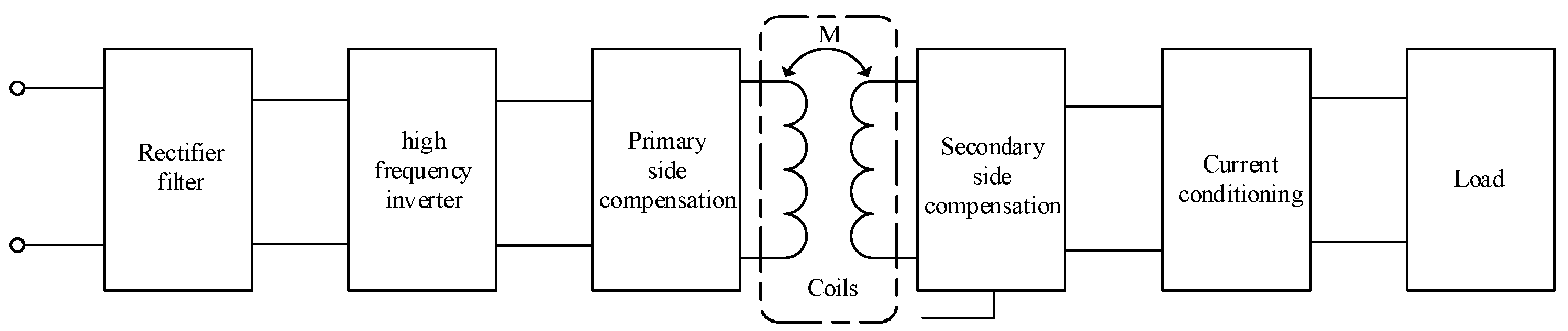
2.2. Magnetic Field Coupled Wireless Power Transmission
2.2.1. Basic Structure
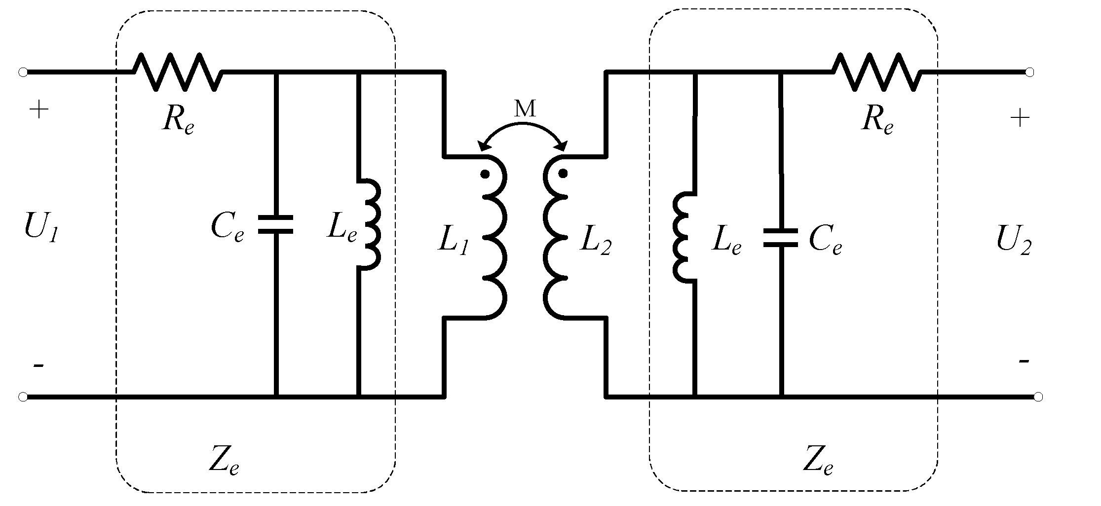
2.2.2. Working Principle
3. Research on Key Technologies
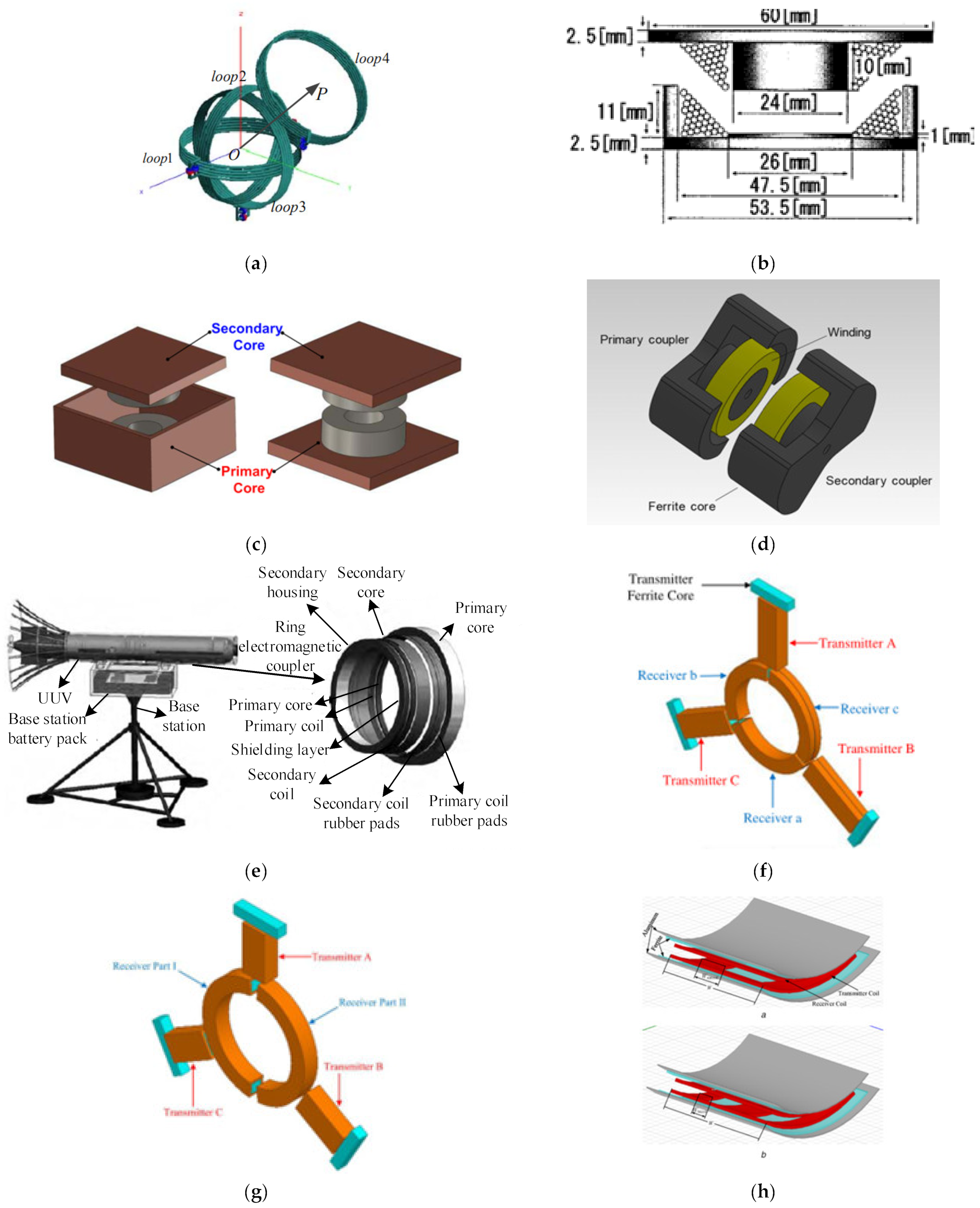
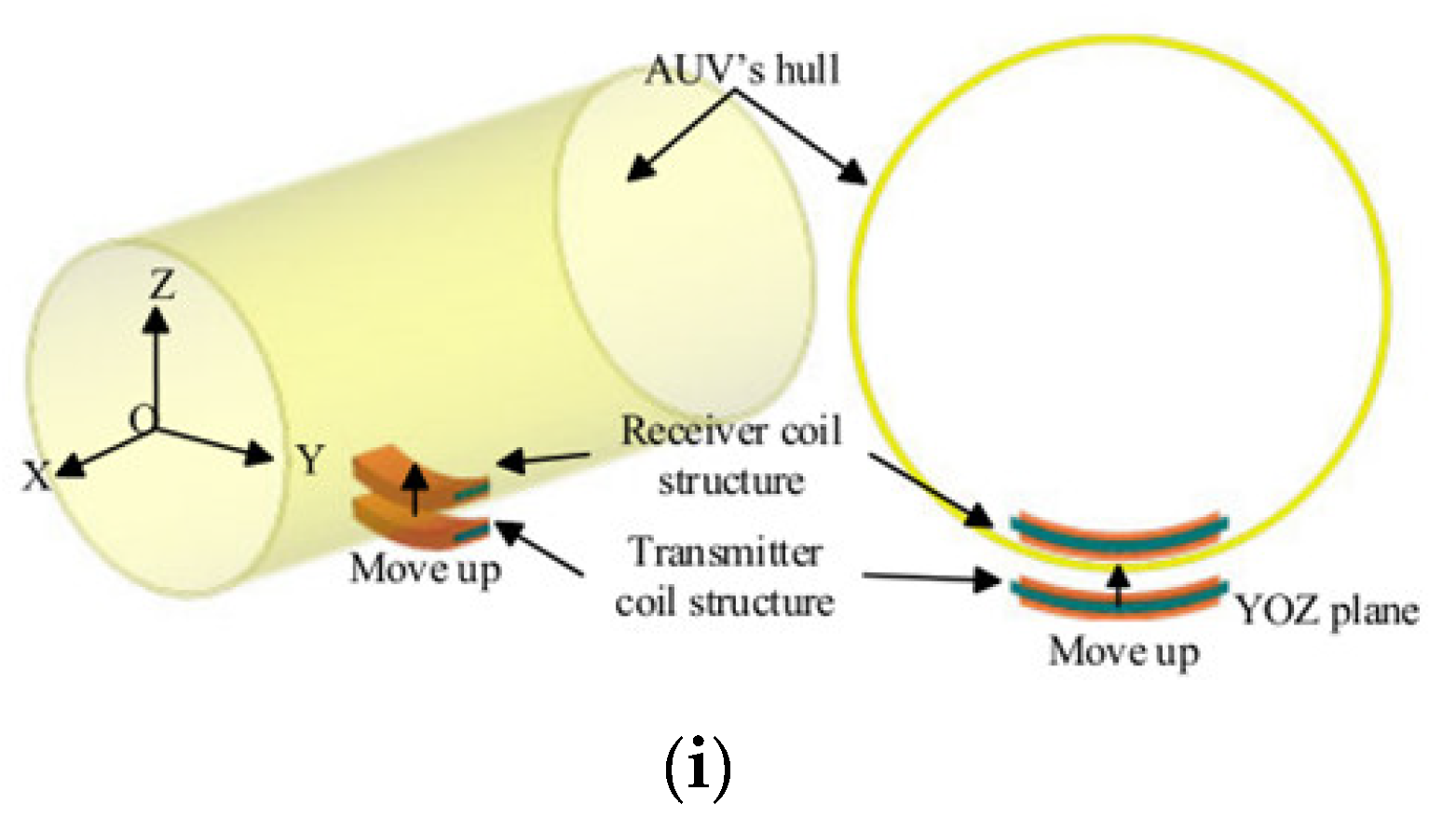
3.1. Magnetic Couplers Based on Loosely Coupled Transformer Principle
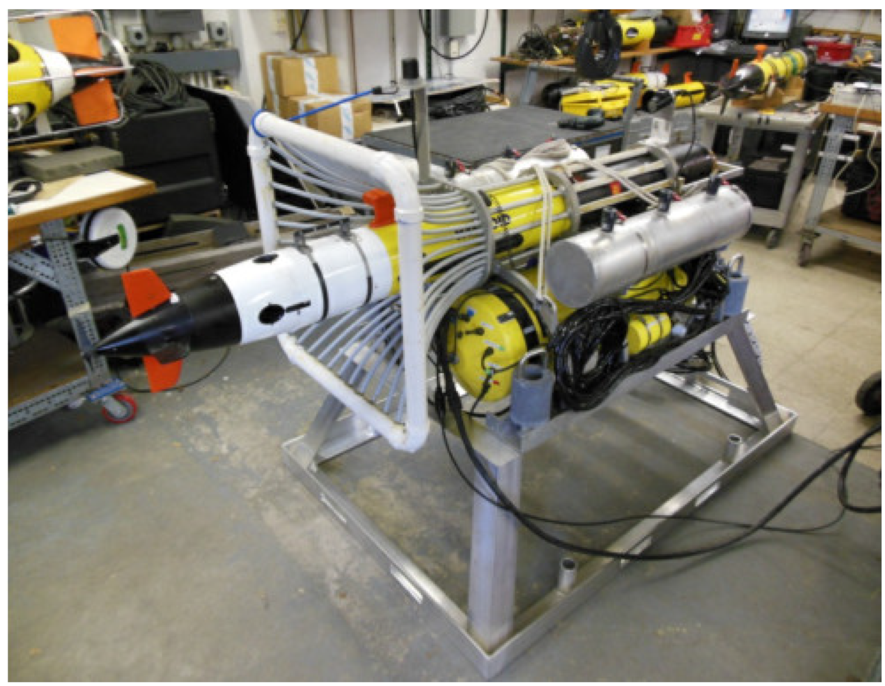
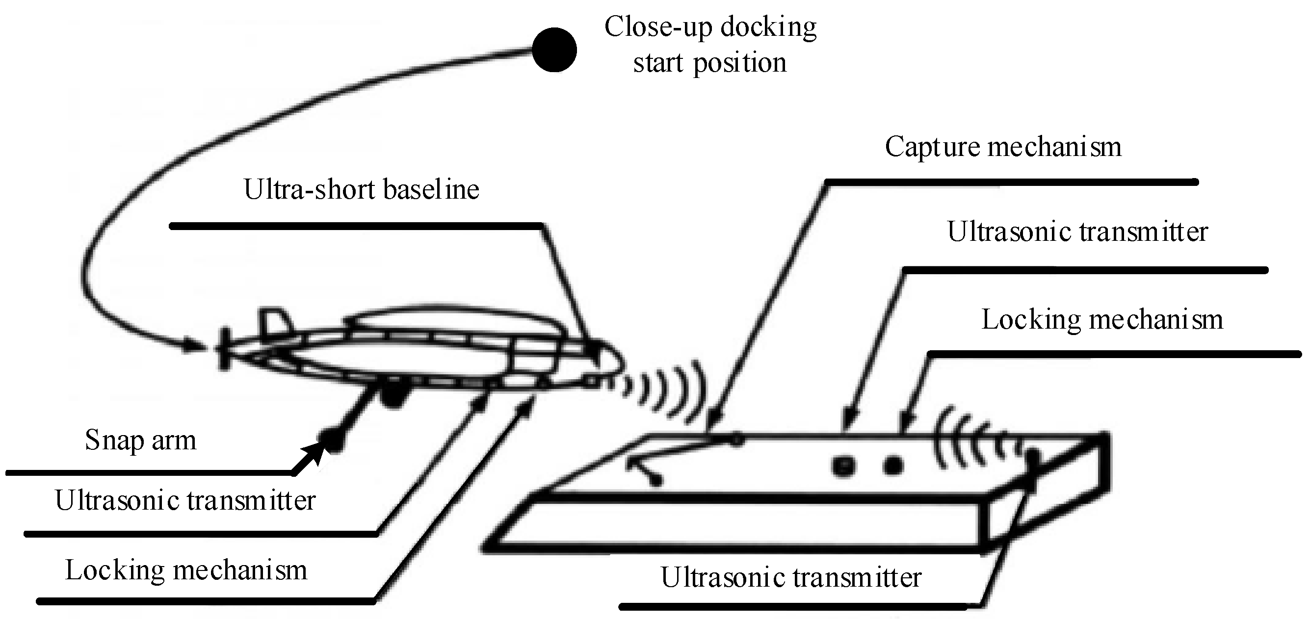
3.2. AUV Underwater Docking Method
- Snap docking;
- 2.
- Inclusive docking;
- 3.
- Platform docking.
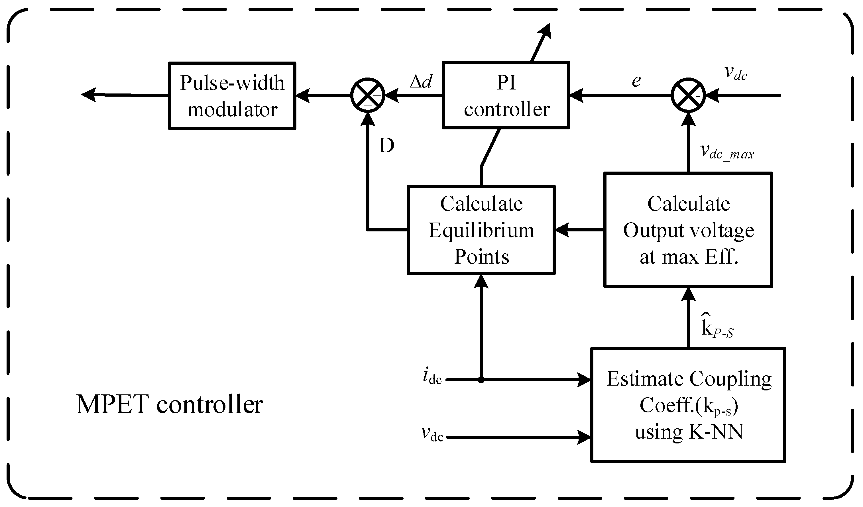
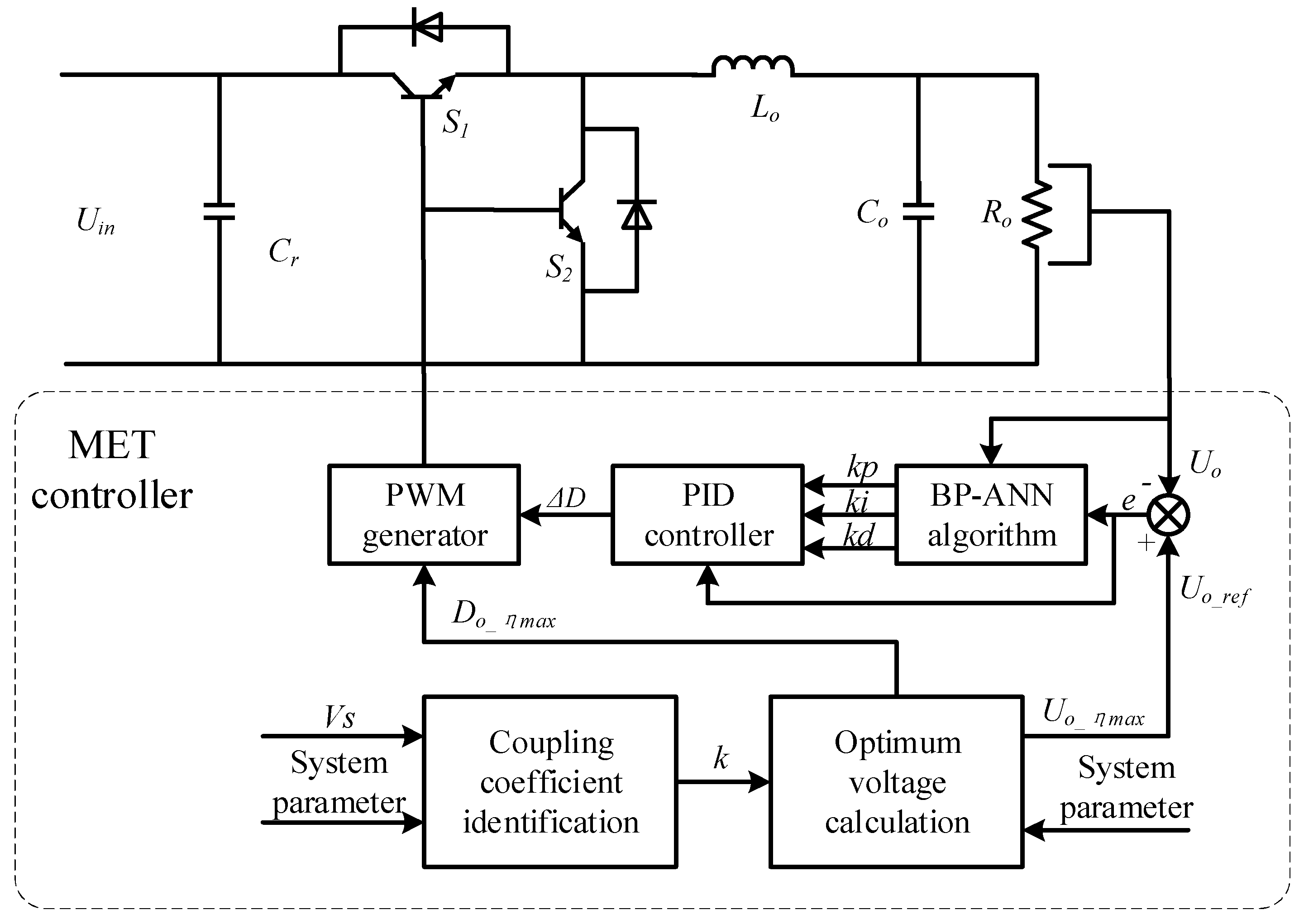
3.3. Control Mode
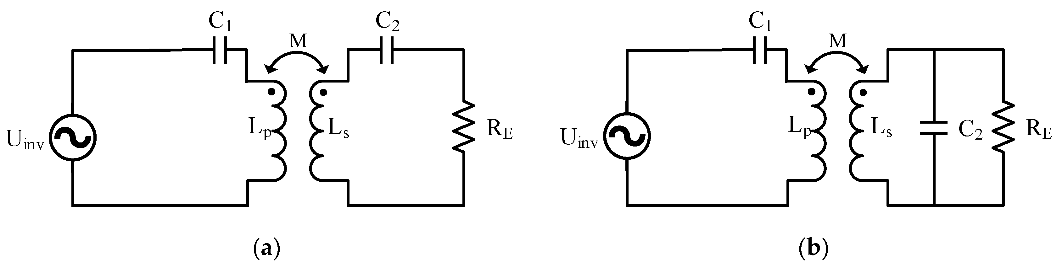
3.4. Compensation Topology
3.4.1. Low-Order Compensation Topology in WPT

| Topologies | Characteristics |
|---|---|
|
|
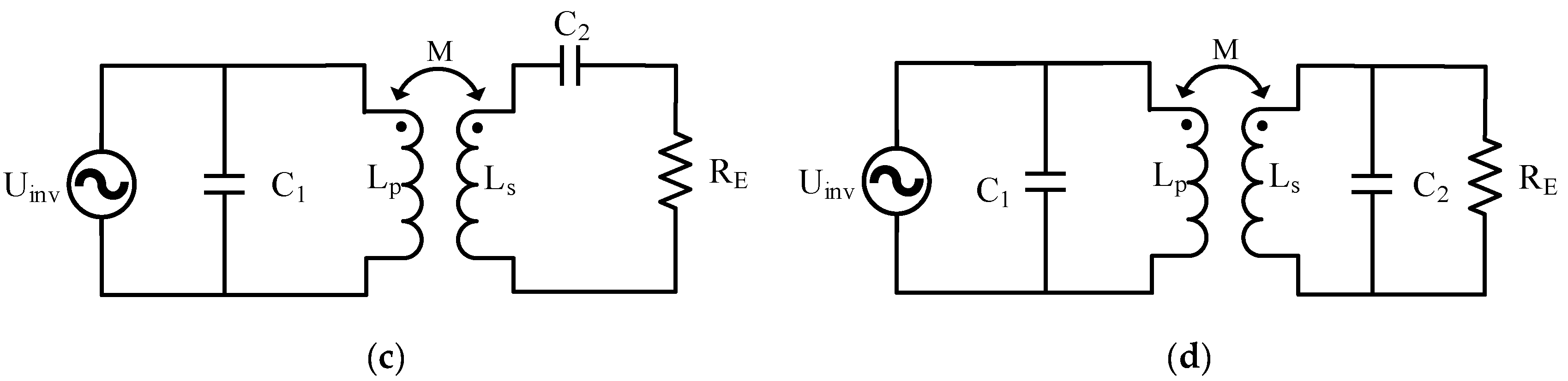
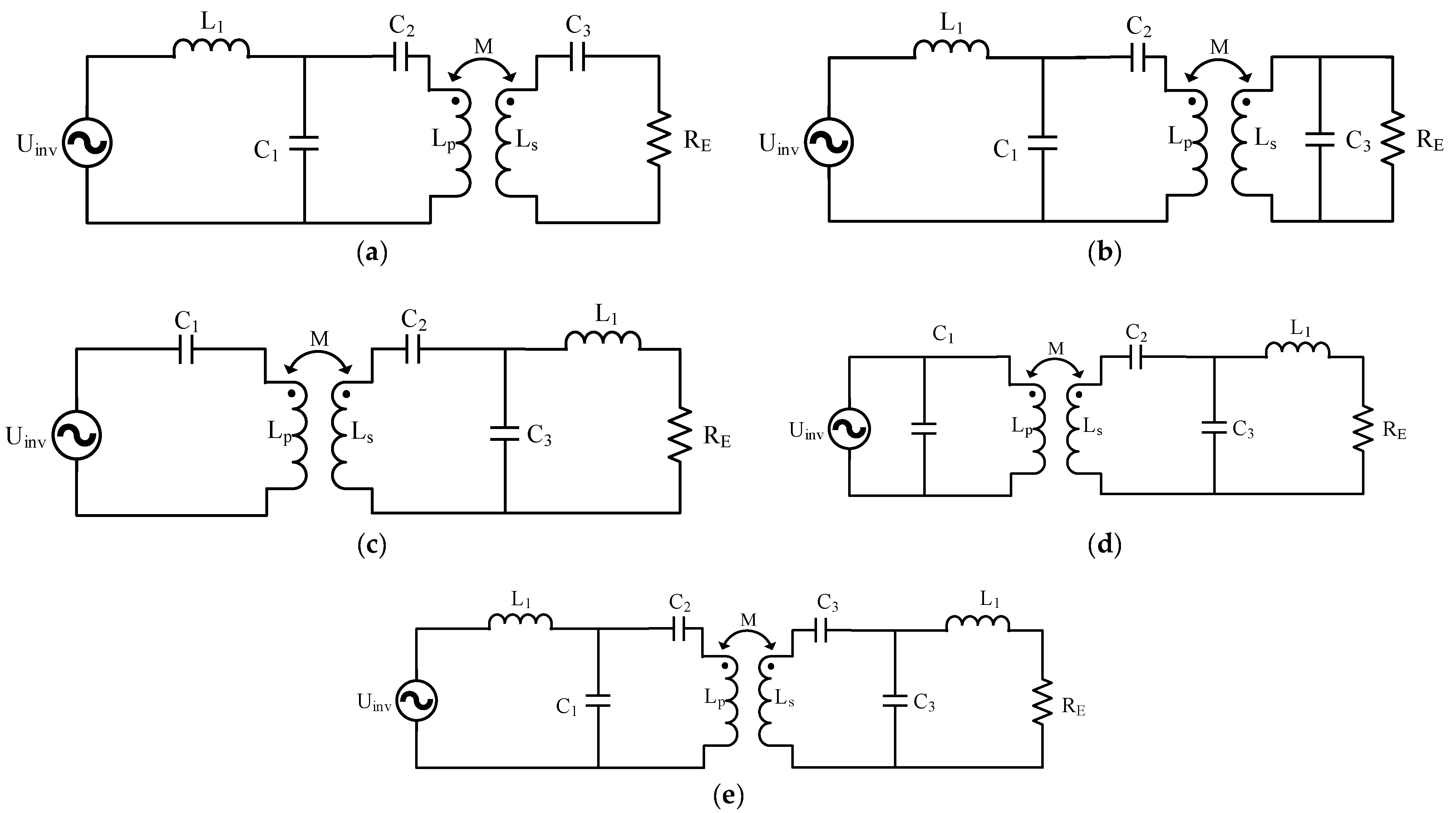
3.4.2. Higher-Order Topology in WPT
3.5. Calculation of Eddy Current Loss in Seawater under Magnetically Coupled Resonance
4. Key Issues to Be Solved and Development Trend
4.1. Technical Principle of WPT in Seawater
4.2. IWPT System Implementation on an AUV
4.3. Communication and Data Transfer
4.4. Adaptability to the Marine Environment
4.5. Electromagnetic Compatibility
4.6. Application of New Materials
5. Conclusions
Funding
Data Availability Statement
Conflicts of Interest
References
- Wen, H.; Song, B.; Zhang, K. Underwater Magnetically coupled resonant radio energy transmission technology and its application. J. Underw. Unmanned Syst. 2019, 27, 361–368. [Google Scholar]
- Bradley, A.M.; Feezor, M.D.; Singh, H. Power systems for autonomous underwater vehicles. IEEE J. Ocean. Eng. 2001, 26, 526–538. [Google Scholar] [CrossRef]
- Jurdak, R.; Lopes, C.V.; Baldi, P. Battery lifetime estimation and optimization for underwater sensor networks. IEEE Sens. Netw. Oper. 2004, 2006, 397–420. [Google Scholar]
- Wu, X.; Sun, P.; Yang, S. A review of underwater radio energy transmission technology and its application. Trans. China Electrotech. Soc. 2019, 34, 1559–1568. [Google Scholar]
- Villa, J.L.; Sallan, J.; Osorio, J.F.S. High-misalignment tolerant compensation topology for ICPT systems. IEEE Trans. Ind. Electron. 2011, 59, 945–951. [Google Scholar] [CrossRef]
- Hou, J.; Chen, G.; Ren, X. Analysis of Time Domain Characteristics of S/SP Non-contact Resonant Converter. Proc. CSEE 2015, 35, 1983–1992. [Google Scholar]
- Kim, S.; Covic, G.A.; Boys, J.T. Comparison of tripolar and circular pads for IPT charging systems. IEEE Trans. Power Electron. 2017, 33, 6093–6103. [Google Scholar] [CrossRef]
- Waters, B.H.; Mahoney, B.J.; Lee, G.; Smith, J.R. Optimal coil size ratios for wireless power transfer applications. In Proceedings of the 2014 IEEE International Symposium on Circuits and Systems (ISCAS), Melbourne, VIC, Australia, 1–5 June 2014; pp. 2045–2048. [Google Scholar]
- Wen, F.; Chu, X.; Li, Q.; Li, R.; Liu, L.; Jing, F. Optimization on Three-Coil Long-Range and Dimension-Asymmetric Wireless Power Transfer System. IEEE Trans. Electromagn. Compat. 2020, 62, 1859–1868. [Google Scholar] [CrossRef]
- Adepoju, W.O.; Bhattacharya, I.; Bima, M.E.; Banik, T. Novel Metamaterial and AI-based Multi-Objective Optimization of Coil Parameters for Efficient Wireless Power Transfer. In Proceedings of the 2021 IEEE Vehicle Power and Propulsion Conference (VPPC), Gijon, Spain, 25–28 October 2021. [Google Scholar]
- Yan, Y.; Shi, W.; Zhang, X. Design of UAV wireless power transmission system based on coupling coil structure optimization. EURASIP J. Wirel. Commun. Netw. 2020, 1, 1–13. [Google Scholar] [CrossRef]
- Jeong, S.Y.; Kwak, H.G.; Jang, G.C. Dual-purpose nonoverlapping coil sets as metal object and vehicle position detections for wireless stationary EV chargers. IEEE Trans. Power Electron. 2017, 33, 7387–7397. [Google Scholar] [CrossRef]
- Xiang, L.; Zhu, Z.; Tian, J.; Tian, Y. Foreign Object Detection in a Wireless Power Transfer System Using Symmetrical Coil Sets. IEEE Access 2019, 7, 44622–44631. [Google Scholar] [CrossRef]
- Zhang, Y.; Yan, Z.; Zhu, J. A review of foreign object detection (FOD) for inductive power transfer systems. eTransportation 2019, 1, 100002. [Google Scholar] [CrossRef]
- Oiler, J.; Anderson, G.; Bana, V.; Phipps, A.; Kerber, M. Thermal and biofouling effects on underwater wireless power transfer. In Proceedings of the 2015 IEEE Wireless Power Transfer Conference (WPTC), Boulder, CO, USA, 13–15 May 2015. [Google Scholar]
- Zhang, K.; Du, L.; Zhu, Z. A normalization method of delimiting the electromagnetic hazard region of a wireless power transfer system. IEEE Trans. Electromagn. Compat. 2017, 60, 829–839. [Google Scholar] [CrossRef]
- Mohsan, S.A.H.; Islam, A.; Khan, M.A. A review on research challenges limitations and practical solutions for underwater wireless power transfer. Int. J. Adv. Comput. Sci. Appl. (IJACSA) 2020, 11, 554–562. [Google Scholar] [CrossRef]
- Zhou, J.; Guo, K.; Chen, Z. Design considerations for contact-less underwater power delivery: A systematic review and critical analysis. Wirel. Power Transf. 2020, 7, 76–85. [Google Scholar] [CrossRef]
- Duan, L. Research on Two-Way Radio Energy Transmission Technology of Autonomous Underwater Vehicle; Shandong University: Jinan, China, 2020. [Google Scholar]
- Fu, Y. Research on Radio Energy Transmission Technology of Underwater Measuring Device; China Ship Research Institute: Beijing, China, 2015. [Google Scholar]
- Yeo, T.D.; Kwon, D.S.; Khang, S.T. Design of maximum efficiency tracking control scheme for closed-loop wireless power charging system employing series resonant tank. IEEE Trans. Power Electron. 2016, 32, 471–478. [Google Scholar] [CrossRef]
- Sample, A.P.; Meyer, D.T.; Smith, J.R. Analysis, experimental results, and range adaptation of magnetically coupled resonators for wireless power transfer. IEEE Trans. Ind. Electron. 2010, 58, 544–554. [Google Scholar] [CrossRef]
- Budhia, M.; Covic, G.A.; Boys, J.T. Design and optimization of circular magnetic structures for lumped inductive power transfer systems. IEEE Trans. Power Electron. 2011, 26, 3096–3108. [Google Scholar] [CrossRef]
- Niu, W.; Gu, W.; Chu, J. Analysis and experimental results of frequency splitting of underwater wireless power transfer. J. Eng. 2017, 2017, 385–390. [Google Scholar] [CrossRef]
- Niu, W.; Gu, W.; Chu, J. Frequency splitting of underwater wireless power transfer. In Proceedings of the IEEE International Workshop on Electromagnetics: Applications and Student Innovation Competition (iWEM), Nanjing, China, 16–18 May 2016; pp. 1–3. [Google Scholar]
- Huang, R.; Zhang, B.; Qiu, D. Frequency splitting phenomena of magnetic resonant coupling wireless power transfer. IEEE Trans. Magn. 2014, 50, 1–4. [Google Scholar] [CrossRef]
- Lyu, Y.L.; Meng, F.Y.; Yang, G.H. A method of using nonidentical resonant coils for frequency splitting elimination in wireless power transfer. IEEE Trans. Power Electron. 2015, 30, 6097–6107. [Google Scholar] [CrossRef]
- Chen, G. Research on Key Technologies of Wireless Charging for Underwater Cable Inspection Robot; Chongqing University: Chongqing, China, 2019. [Google Scholar]
- Green, A.W.; Boys, J.T. Inductively coupled power transmission-concept, design, and application. Trans. Inst. Prof. Eng. N. Z. Electr./Mech./Chem. Eng. Sect. 1995, 22, 1–9. [Google Scholar]
- Ko, Y.D.; Jang, Y.J. The optimal system design of the online electric vehicle utilizing wireless power transmission technology. IEEE Trans. Intell. Transp. Syst. 2013, 14, 1255–1265. [Google Scholar] [CrossRef]
- Hui, S.Y.R.; Ho, W.W.C. A new generation of universal contactless battery charging platform for portable consumer electronic equipment. IEEE Trans. Power Electron. 2005, 20, 620–627. [Google Scholar] [CrossRef]
- Xue, R.F.; Cheng, K.W.; Je, M. High-efficiency wireless power transfer for biomedical implants by optimal resonant load transformation. IEEE Trans. Circuits Syst. I Regul. Pap. 2012, 60, 867–874. [Google Scholar] [CrossRef]
- De Santis, M.; Cacciotti, I. Wireless implantable and biodegradable sensors for postsurgery monitoring: Current status and future perspectives. Nanotechnology 2020, 31, 252001. [Google Scholar] [CrossRef]
- Kim, H.J.; Hirayama, H.; Kim, S.; Han, K.J.; Zhang, R. Review of near-field wireless power and communication for biomedical applications. IEEE Access 2017, 5, 21264–21285. [Google Scholar] [CrossRef]
- Tesla, N. Experiments with alternate currents of very high frequency and their application to methods of artificial illumination. Trans. Am. Inst. Electr. Eng. 1891, 8, 266–319. [Google Scholar] [CrossRef]
- Tesla, N. The Inventions Researches and Writings of Nikola Tesla; Barnes & Noble: New York, NY, USA, 2014. [Google Scholar]
- Dai, J.; Ludois, D.C. A survey of wireless power transfer and a critical comparison of inductive and capacitive coupling for small gap applications. IEEE Trans. Power Electron. 2015, 30, 6017–6029. [Google Scholar] [CrossRef]
- Urano, M.; Takahashi, A. Study on underwater wireless power transfer via electric coupling. In Proceedings of the 2016 IEEE International Meeting for Future of Electron Devices, Kansai (IMFEDK), Kyoto, Japan, 23–24 June 2016; pp. 1–2. [Google Scholar]
- Brown, W.C. The history of power transmission by radio waves. IEEE Trans. Microw. Theory Tech. 1984, 32, 1230–1242. [Google Scholar] [CrossRef] [Green Version]
- Shizuno, K.; Yoshida, S.; Tanomura, M. Long distance high efficient underwater wireless charging system using dielectric-assist antenna. In Proceedings of the 2014 Oceans—St. John’s, St. John’s, NL, Canada, 14–19 September 2014; pp. 1–3. [Google Scholar]
- Yoshida, S.; Tanomura, M.; Hama, Y. Underwater wireless power transfer for non-fixed unmanned underwater vehicle in the ocean. In Proceedings of the IEEE/OES Autonomous Underwater Vehicles (AUV), Tokyo, Japan, 6–9 November 2016; pp. 177–180. [Google Scholar]
- Sasaki, S.; Tanaka, K.; Maki, K. Microwave power transmission technologies for solar power satellites. Proc. IEEE 2013, 101, 1438–1447. [Google Scholar] [CrossRef]
- Ishiyama, T.; Kanai, Y.; Ohwaki, J. Impact of a wireless power transmission system using an ultrasonic air transducer for low-power mobile applications. In Proceedings of the IEEE Symposium on Ultrasonics 2003, Honolulu, HI, USA, 5–8 October 2003; Volume 2, pp. 1368–1371. [Google Scholar]
- Roes, M.G.L.; Hendrix, M.A.M.; Duarte, J.L. Contactless energy transfer through air by means of ultrasound. In Proceedings of the IECON 2011-37th Annual Conference of the IEEE Industrial Electronics Society, Melbourne, VIC, Australia, 7–10 November 2011; pp. 1238–1243. [Google Scholar]
- Roes, M.G.L.; Duarte, J.L.; Hendrix, M.A.M.; Lomonova, E.A. Acoustic energy transfer: A review. IEEE Trans. Ind. Electron. 2013, 60, 242–248. [Google Scholar] [CrossRef]
- Chang, T.; Weber, M.J.; Wang, M. Design of tunable ultrasonic receivers for efficient powering of implantable medical devices with reconfigurable power loads. IEEE Trans. Ultrason. Ferroelectr. Freq. Control 2016, 63, 1554–1562. [Google Scholar] [CrossRef]
- Zou, Y.; Huang, X.; Bai, Y. Research on ultrasonic contactless energy transmission system based on PZT. Trans. China Electrotech. Soc. 2011, 26, 144–150. [Google Scholar]
- Glaser, P.E. Power from the sun: Its future. Science 1968, 162, 857–861. [Google Scholar] [CrossRef]
- Wu, T.C.; Chi, Y.C.; Wang, H.Y. Blue laser diode enables underwater communication at 12.4 Gbps. Sci. Rep. 2017, 7, 1–10. [Google Scholar] [CrossRef]
- Kurs, A.; Karalis, A.; Moffatt, R. Wireless power transfer via strongly coupled magnetic resonances. Science 2007, 317, 83–86. [Google Scholar] [CrossRef] [Green Version]
- Zhou, J. Optimization of Non-Contact Power Transmission Efficiency in Seawater Environment; Zhejiang University: Hangzhou, China, 2014. [Google Scholar]
- Teeneti, C.R.; Truscott, T.T.; Beal, D.N. Review of wireless charging systems for autonomous underwater vehicles. IEEE J. Ocean. Eng. 2019, 46, 68–87. [Google Scholar] [CrossRef]
- Yang, M. Research on Non-Contact Inductive Coupling Power Transmission and Control Technology and Its Application; Hunan University: Changsha, China, 2012. [Google Scholar]
- Li, K. Research on Key Technologies of Autonomous Underwater Vehicles Underwater Docking and Docking Collision Problem; Harbin Engineering University: Harbin, China, 2017; pp. 17–27. [Google Scholar]
- He, Z.; Wang, Y.; Ding, L. Research on three-dimensional omnidirectional wireless power transfer system for subsea operation. In Proceedings of the OCEANS 2017-Aberdeen, Aberdeen, UK, 19–22 June 2017; pp. 1–5. [Google Scholar]
- Kojiya, T.; Sato, F.; Matsuki, H. Automatic power supply system to underwater vehicles utilizing non-contacting technology. In Proceedings of the Oceans’ 04 MTS/IEEE Techno-Ocean’04 (IEEE Cat. No. 04CH37600), Kobe, Japan, 9–12 November 2004; Volume 4, pp. 2341–2345. [Google Scholar]
- Cheng, Z.; Lei, Y.; Song, K. Design and loss analysis of loosely coupled transformer for an underwater high-power inductive power transfer system. IEEE Trans. Magn. 2014, 51, 1–10. [Google Scholar]
- Zhou, J.; Li, D.; Chen, Y. Frequency selection of an inductive contactless power transmission system for ocean observing. Ocean Eng. 2013, 60, 175–185. [Google Scholar] [CrossRef]
- Wang, J.; Song, B.; Duan, G. Research on Non-contact Electric Energy Transmission Technology for Underwater Vehicles. Electr. Mach. Control 2014, 18, 36–41. [Google Scholar]
- Kan, T.; Zhang, Y.; Yan, Z. A rotation-resilient wireless charging system for lightweight autonomous underwater vehicles. IEEE Trans. Veh. Technol. 2018, 67, 6935–6942. [Google Scholar] [CrossRef]
- Kan, T.; Mai, R.; Mercier, P.P. Design and analysis of a three-phase wireless charging system for lightweight autonomous underwater vehicles. IEEE Trans. Power Electron. 2017, 33, 6622–6632. [Google Scholar] [CrossRef]
- Yan, Z.; Zhang, Y.; Zhang, K. Underwater wireless power transfer system with a curly coil structure for AUVs. IET Power Electron. 2019, 12, 2559–2565. [Google Scholar] [CrossRef] [Green Version]
- Cai, C.; Zhang, Y.; Wu, S. A circumferential coupled dipole-coil magnetic coupler for autonomous underwater vehicles wireless charging applications. IEEE Access 2020, 8, 65432–65442. [Google Scholar] [CrossRef]
- Askari, A.; Stark, R.; Curran, J. Underwater wireless power transfer. In Proceedings of the 2015 IEEE Wireless Power Transfer Conference (WPTC), Boulder, CO, USA, 13–15 May 2015. [Google Scholar]
- Shi, J.; Li, D.; Yang, C. Design and analysis of an underwater inductive coupling power transfer system for autonomous underwater vehicle docking applications. J. Zhejiang Univ. Sci. C 2014, 15, 51–62. [Google Scholar] [CrossRef]
- Bana, V.; Kerber, M.; Anderson, G. Underwater wireless power transfer for maritime applications. In Proceedings of the 2015 IEEE Wireless Power Transfer Conference (WPTC), Boulder, CO, USA, 13–15 May 2015. [Google Scholar]
- McGinnis, T.; Henze, C.P.; Conroy, K. Inductive power system for autonomous underwater vehicles. In Proceedings of the OCEANS 2007, Vancouver, BC, Canada, 29 September–4 October 2007; pp. 1–5. [Google Scholar]
- Li, Z.; Li, D.; Lin, L. Design considerations for electromagnetic couplers in contactless power transmission systems for deep-sea applications. J. Zhejiang Univ. Sci. C 2010, 11, 824–834. [Google Scholar] [CrossRef]
- Wang, S.; Song, B.; Duan, G. Automatic wireless power supply system to autonomous underwater vehicles by means of electromagnetic coupler. J. Shanghai Jiaotong Univ. (Sci.) 2014, 19, 110–114. [Google Scholar] [CrossRef]
- Yan, Z.; Zhang, K.; Wen, H. Research on characteristics of contactless power transmission device for autonomous underwater vehicle. In Proceedings of the OCEANS 2016-Shanghai, Shanghai, China, 10–13 April 2016; pp. 1–5. [Google Scholar]
- Yan, K.; Wu, L. Research on Key Technologies of AUV Underwater Docking. Robot 2007, 29, 77–83. [Google Scholar]
- Singh, H.; Bellingham, J.G.; Hover, F. Docking for an autonomous ocean sampling network. IEEE J. Ocean. Eng. 2001, 26, 498–514. [Google Scholar] [CrossRef]
- Purcell, M. The REMUS AUV docking system: Overview and test results. MTS/OCC 98 1998, 2, 886–890. [Google Scholar]
- Allen, B.; Austin, T.; Forrester, N. Autonomous docking demonstrations with enhanced REMUS technology. In Proceedings of the OCEANS 2006, Boston, MA, USA, 18–21 September 2006; pp. 1–6. [Google Scholar]
- Page, B.R. Design of a Mobile Underwater Charging System. Master’s Thesis, Michigan Technological University, Houghton, MI, USA, 2016. [Google Scholar]
- Cena, J.M. Power Transfer Efficiency of Mutually Coupled Coils in an Aluminum AUV Hull; Naval Postgraduate School: Monterey, CA, USA, 2013. [Google Scholar]
- Kawasaki, T.; Fukasawa, T.; Noguchi, T. Development of AUV “Marine Bird” with underwater docking and recharging system. In Proceedings of the 2003 International Conference Physics and Control. Proceedings (Cat. No. 03EX708), Tokyo, Japan, 25–27 June 2003; pp. 166–170. [Google Scholar]
- Kawasaki, T.; Noguchi, T.; Fukasawa, T. “Marine Bird”, a new experimental AUV-results of docking and electric power supply tests in sea trials. In Proceedings of the Oceans’ 04 MTS/IEEE Techno-Ocean’04 (IEEE Cat. No. 04CH37600), Kobe, Japan, 9–12 November 2004; Volume 3, pp. 1738–1744. [Google Scholar]
- Patil, D.; Mcdonough, M.K.; Miller, J.M. Wireless power transfer for vehicular applications: Overview and challenges. IEEE Trans. Transp. Electrif. 2017, 4, 3–37. [Google Scholar] [CrossRef]
- Sanborn, G.; Phipps, A. Standards and methods of power control for variable power bidirectional wireless power transfer. In Proceedings of the 2017 IEEE Wireless Power Transfer Conference (WPTC), Taipei, Taiwan, 10–12 May 2017; pp. 1–4. [Google Scholar]
- Feng, L.; Zhu, C.; Zhang, J. Research on Key Technology of Underwater Wireless Charging for AUV. Ship Sci. Technol. 2020, 42, 159–162. [Google Scholar]
- Li, H.; Li, J.; Wang, K. A maximum efficiency point tracking control scheme for wireless power transfer systems using magnetic resonant coupling. IEEE Trans. Power Electron. 2014, 30, 3998–4008. [Google Scholar] [CrossRef]
- Orekan, T.; Zhang, P.; Shih, C. Analysis, design, and maximum power-efficiency tracking for undersea wireless power transfer. IEEE J. Emerg. Sel. Top. Power Electron. 2017, 6, 843–854. [Google Scholar] [CrossRef]
- Zheng, Z.; Wang, N.; Ahmed, S. Maximum efficiency tracking control of underwater wireless power transfer system using artificial neural networks. Proc. Inst. Mech. Eng. Part I J. Syst. Control Eng. 2021, 235, 1819–1829. [Google Scholar] [CrossRef]
- Zhang, W.; Mi, C.C. Compensation topologies of high-power wireless power transfer systems. IEEE Trans. Veh. Technol. 2015, 65, 4768–4778. [Google Scholar] [CrossRef]
- Sohn, Y.H.; Choi, B.H.; Lee, E.S. General unified analyses of two-capacitor inductive power transfer systems: Equivalence of current-source SS and SP compensations. IEEE Trans. Power Electron. 2015, 30, 6030–6045. [Google Scholar] [CrossRef]
- Zhang, W.; Wong, S.C.; Tse, C.K.; Chen, Q. An Optimized Track Length in Roadway Inductive Power Transfer Systems. IEEE J. Emerg. Sel. Top. Power Electron. 2014, 2, 598–608. [Google Scholar] [CrossRef]
- Khaligh, A.; Dusmez, S. Comprehensive Topological Analysis of Conductive and Inductive Charging Solutions for Plug-In Electric Vehicles. IEEE Trans. Veh. Technol. 2012, 61, 3475–3489. [Google Scholar] [CrossRef]
- McDonough, M.K. A Multi-Port Power Electronics Interface for Battery Powered Electric Vehicles: Application of Inductively Coupled Wireless Power Transfer and Hybrid Energy Storage System; The University of Texas at Dallas: Richardson, TX, USA, 2014. [Google Scholar]
- Aditya, K.; Williamson, S.S. Design considerations for loosely coupled inductive power transfer (IPT) system for electric vehicle battery charging—A comprehensive review. In Proceedings of the 2014 IEEE Transportation Electrification Conference and Expo (ITEC), Dearborn, MI, USA, 15–18 June 2014. [Google Scholar]
- Kim, S.; Park, H.H.; Kim, J.; Kim, J.; Ahn, S. Design and Analysis of a Resonant Reactive Shield for a Wireless Power Electric Vehicle. IEEE Trans. Microw. Theory Tech. 2014, 62, 1057–1066. [Google Scholar] [CrossRef]
- Choi, S.Y.; Gu, B.W.; Lee, S.W.; Lee, W.Y.; Huh, J.; Rim, C.T. Generalized Active EMF Cancel Methods for Wireless Electric Vehicles. IEEE Trans. Power Electron. 2014, 29, 5770–5783. [Google Scholar] [CrossRef]
- Park, C.; Lee, S.; Jeong, S.Y. Uniform power I-type inductive power transfer system with DQ-power supply rails for on-line electric vehicles. IEEE Trans. Power Electron. 2015, 30, 6446–6455. [Google Scholar] [CrossRef]
- Zhang, W.; Wong, S.C.; Chi, K.T. Design for Efficiency Optimization and Voltage Controllability of Series-Series Compensated Inductive Power Transfer Systems. IEEE Trans. Power Electron. 2013, 29, 191–200. [Google Scholar] [CrossRef]
- Kim, J.; Kim, K.; Kim, H. An efficient modeling for underwater wireless power transfer using Z-parameters. IEEE Trans. Electromagn. Compat. 2019, 61, 2006–2014. [Google Scholar] [CrossRef]
- Miller, J.M.; Onar, O.C.; Chinthavali, M. Primary-side power flow control of wireless power transfer for electric vehicle charging. IEEE J. Emerg. Sel. Top. Power Electron. 2014, 3, 147–162. [Google Scholar] [CrossRef]
- Li, J.; Zhao, H.; Lei, M. Research on SP compensation topology of electromagnetic resonant Wireless Charging. Comput. Digit. Eng. 2017, 45, 670–674. [Google Scholar]
- Xin, P.; Zhou, J.; Feng, J. T-parameter Model and Its Application in S/P Compensation WPT System. New Technol. Electr. Energy 2018, 37, 42–48. [Google Scholar]
- Nagendra, G.R.; Covic, G.A.; Boys, J.T. Sizing of inductive power pads for dynamic charging of EVs on IPT highways. IEEE Trans. Transp. Electrif. 2017, 3, 405–417. [Google Scholar] [CrossRef]
- Tang, F.; Zhang, K.; Yan, W. Frequency control of non-contact charging system for underwater autonomous vehicle. Electr. Autom. 2012, 34, 76–78. [Google Scholar]
- Yan, Z.; Zhang, Y.; Zhang, K.; Song, B.; Li, S.; Kan, T.; Mi, C.C. Fault-Tolerant Wireless Power Transfer System with a Dual-Coupled LCC-S Topology. IEEE Trans. Veh. Technol. 2019, 68, 11838–11846. [Google Scholar] [CrossRef]
- Liu, P.; Gao, T.; Zhao, R.; Mao, Z. A Novel Conformal Coil Structure Design of Wireless Power Transfer System for Autonomous Underwater Vehicles. J. Mar. Sci. Eng. 2022, 10, 875. [Google Scholar] [CrossRef]
- Zhang, P.; Gong, L.; Yao, F. Analysis of compensation network of S-LCC radio energy transmission system. Sci. Technol. Eng. 2022, 22, 9669–9678. [Google Scholar]
- Yang, Y.; Zhang, Y. A dual load wireless power transmission system based on S-LCC topology. Power Electron. 2021, 55, 37–40. [Google Scholar]
- Yan, Z.; Zhang, Y.; Song, B. An LCC-P compensated wireless power transfer system with a constant current output and reduced receiver size. Energies 2019, 12, 172. [Google Scholar] [CrossRef] [Green Version]
- Zhao, L. Research on Key Technologies of Underwater Radio Energy Transmission System; Southwest University of Science and Technology: Mianyang, China, 2021. [Google Scholar]
- Peng, L.; Li, X.; Zhu, G.R. Characteristics research on double LCC compensation converter in the inductive energy transfer system. In Proceedings of the 2015 International Conference on Industrial Informatics-Computing Technology, Intelligent Technology, Industrial Information Integration, Wuhan, China, 3–4 December 2015; pp. 243–246. [Google Scholar]
- Xu, W.; Qian, X. Parameter Optimization for Anti-Migration Performance of Double-Sided LCC Topology. Low Volt. Appar. 2021, 5, 17–24. [Google Scholar]
- Huang, C.Y.; Boys, J.T.; Covic, G.A. LCL pickup circulating current controller for inductive power transfer systems. IEEE Trans. Power Electron. 2012, 28, 2081–2093. [Google Scholar] [CrossRef]
- Li, S.; Li, W.; Deng, J.; Nguyen, T.D.; Mi, C.C. A Double-Sided LCC Compensation Network and Its Tuning Method for Wireless Power Transfer. IEEE Trans. Veh. Technol. 2015, 64, 2261–2273. [Google Scholar] [CrossRef]
- Li, W.; Zhao, H.; Li, S.; Deng, J.; Kan, T.; Mi, C.C. Integrated LCC Compensation Topology for Wireless Charger in Electric and Plug-in Electric Vehicles. IEEE Trans. Ind. Electron. 2015, 62, 4215–4225. [Google Scholar] [CrossRef]
- Si, P.; Hu, A.P. Analyses of DC Inductance Used in ICPT Power Pick-Ups for Maximum Power Transfer. In Proceedings of the 2005 IEEE/PES Transmission & Distribution Conference & Exposition: Asia and Pacific, Dalian, China, 18 August 2005; pp. 1–6. [Google Scholar]
- Zhao, L.; Thrimawithana, D.J.; Madawala, U.K. Hybrid bidirectional wireless EV charging system tolerant to pad misalignment. IEEE Trans. Ind. Electron. 2017, 64, 7079–7086. [Google Scholar] [CrossRef]
- Zhao, L.; Thrimawithana, D.J.; Madawala, U.K. A misalignment-tolerant series-hybrid wireless EV charging system with integrated magnetics. IEEE Trans. Power Electron. 2018, 34, 1276–1285. [Google Scholar] [CrossRef]
- Zhu, Q.; Wang, L.; Guo, Y. Applying LCC compensation network to dynamic wireless EV charging system. IEEE Trans. Ind. Electron. 2016, 63, 6557–6567. [Google Scholar] [CrossRef]
- Feng, H.; Cai, T.; Duan, S. An LCC-compensated resonant converter optimized for robust reaction to large coupling variation in dynamic wireless power transfer. IEEE Trans. Ind. Electron. 2016, 63, 6591–6601. [Google Scholar] [CrossRef]
- Zhang, K.; Zhu, Z.; Song, B. A power distribution model of magnetic resonance WPT system in seawater. In Proceedings of the 2016 IEEE 2nd Annual Southern Power Electronics Conference (SPEC), Auckland, New Zealand, 5–8 December 2016; pp. 1–4. [Google Scholar]
- Sullivan, C.R. Optimal choice for number of strands in a litz-wire transformer winding. IEEE Trans. Power Electron. 1999, 14, 283–291. [Google Scholar] [CrossRef] [Green Version]
- Tanzania, R.; Choo, F.H.; Siek, L. Design of WPT coils to minimize AC resistance and capacitor stress applied to SS-topology. In Proceedings of the IECON 2015-41st Annual Conference of the IEEE Industrial Electronics Society, Yokohama, Japan, 9–12 November 2015; pp. 000118–000122. [Google Scholar]
- Bagchi, A.C.; Kamineni, A.; Zane, R. Analytical optimization of a Litz wire spiral coil based underwater IPT system. In Proceedings of the 2018 IEEE Energy Conversion Congress and Exposition (ECCE), Portland, OR, USA, 23–27 September 2018; pp. 2456–2463. [Google Scholar]
- Yan, Z.; Song, B.; Zhang, K. Eddy current loss analysis of underwater wireless power transfer systems with misalignments. AIP Adv. 2018, 8, 101421. [Google Scholar] [CrossRef] [Green Version]
- Yan, Z.; Zhang, Y.; Kan, T. Frequency optimization of a loosely coupled underwater wireless power transfer system considering eddy current loss. IEEE Trans. Ind. Electron. 2018, 66, 3468–3476. [Google Scholar] [CrossRef]
- Zhang, K.; Zhang, X.; Zhu, Z. A new coil structure to reduce eddy current loss of WPT systems for underwater vehicles. IEEE Trans. Veh. Technol. 2018, 68, 245–253. [Google Scholar] [CrossRef]
- Zhang, K.H.; Zhu, Z.B.; Du, L.N. Eddy loss analysis and parameter optimization of the WPT system in seawater. J. Power Electron. 2018, 18, 778–788. [Google Scholar]
- Zhang, K.; Ma, Y.; Yan, Z. Eddy current loss and detuning effect of seawater on wireless power transfer. IEEE J. Emerg. Sel. Top. Power Electron. 2018, 8, 909–917. [Google Scholar] [CrossRef]
- Li, Z. Research on Underwater Non-Contact Power Transmission Technology Based on Electromagnetic Induction Principle; Zhejiang University: Hangzhou, China, 2010. [Google Scholar]
- Yan, L. Design of Underwater Non-Contact Power Transmission System Based on MAGNETIC Resonance; Northwestern Polytechnical University: Xi’an, China, 2016. [Google Scholar]
- Feezor, M.D.; Sorrell, F.Y.; Blankinship, P.R. An interface system for autonomous undersea vehicles. IEEE J. Ocean. Eng. 2001, 26, 522–525. [Google Scholar] [CrossRef]
- Manikandan, J.; Vishwanath, A.; Agrawal, V.K.; Korulla, M. Indigenous design and development of underwater wireless power transfer system. In Proceedings of the 2016 Twenty Second National Conference on Communication (NCC), Guwahati, India, 4–6 March 2016. [Google Scholar]
- Ogihara, M.; Ebihara, T.; Mizutani, K. Wireless power and data transfer system for station-based autonomous underwater vehicles. In Proceedings of the OCEANS 2015-MTS/IEEE Washington, Washington, DC, USA, 19–22 October 2015; pp. 1–5. [Google Scholar]
- Orekan, T.; Zhang, P. Underwater Wireless Power Transfer: Smart Ocean Energy Converters; Springer International Publishing: Berlin/Heidelberg, Germany, 2019. [Google Scholar]
- Duarte, C.; Gonçalves, F.; Ressurreição, T. A study on load modulation for underwater wireless power transfer. In Proceedings of the OCEANS 2017-Aberdeen, Aberdeen, UK, 19–22 June 2017; pp. 1–4. [Google Scholar]
- Gonçalves, F.; Pereira, A.; Morais, A. An adaptive system for underwater wireless power transfer. In Proceedings of the 2016 8th International Congress on Ultra Modern Telecommunications and Control Systems and Workshops (ICUMT), Lisbon, Portugal, 18–20 October 2016; pp. 101–105. [Google Scholar]
- Gao, Q.; Wu, X.; Liu, J. Modeling and simulation of contact-less power transformers for underwater application. In Proceedings of the 2009 International Conference on Mechatronics and Automation, Changchun, China, 9–12 August 2009; pp. 1213–1217. [Google Scholar]
- Anderson, G.; Bana, V.; Kerber, M. Marine Fouling and Thermal Dissipation of Undersea Wireless Power Transfer; Space and Naval Warfare Systems Center Pacific: San Diego, CA, USA, 2014. [Google Scholar]
- Ma, Y. Analysis and Research on Characteristics of Magnetically Coupled Resonant Radio Energy Transmission; Lanzhou Jiaotong University: Lanzhou, China, 2017. [Google Scholar]
- Kan, T.; Mai, R.; Mercier, P.P. A three-phase wireless charging system for lightweight autonomous underwater vehicles. In Proceedings of the 2017 IEEE Applied Power Electronics Conference and Exposition (APEC), Tampa, FL, USA, 26–30 March 2017; pp. 1407–1411. [Google Scholar]
- Lu, M.; Ngo, K.D.T. A fast method to optimize efficiency and stray magnetic field for inductive-power-transfer coils using lumped-loops model. IEEE Trans. Power Electron. 2017, 33, 3065–3075. [Google Scholar] [CrossRef]
- Syahroni, N.; Suparno, H.W.; Budiman, H. Characteristics of RAMS coatings using non-ferrous materials for AUVs. In Proceedings of the 2016 International Electronics Symposium (IES), Denpasar, Indonesia, 29–30 September 2016; pp. 209–214. [Google Scholar]
- Zhou, H.; Jiang, Y.; Hu, W. Research and Review on electromagnetic Environment Safety of MAGNETIC resonance Radio Energy Transmission System. Trans. China Electrotech. Soc. 2016, 31, 1–12. [Google Scholar]
- Karalis, A.; Joannopoulos, J.D.; Soljačić, M. Efficient wireless non-radiative mid-range energy transfer. Ann. Phys. 2008, 323, 34–48. [Google Scholar] [CrossRef] [Green Version]
- Do Chung, Y.; Lee, C.Y.; Kim, D.W. Operating characteristics of contactless power transfer from HTS antenna to copper receiver with inserted resonator through large air gap. IEEE Trans. Appl. Supercond. 2013, 24, 1–5. [Google Scholar] [CrossRef]
- Wang, B.; Teo, K.H.; Nishino, T. Experiments on wireless power transfer with metamaterials. Appl. Phys. Lett. 2011, 98, 254101. [Google Scholar] [CrossRef] [Green Version]
- Hu, Y.; Kang, L.; Zheng, W. Impedance matching control method for an underwater magnetic resonance-based wireless power transfer system with metamaterials. J. ElEctromagnEtic WavEs Appl. 2016, 30, 2003–2019. [Google Scholar] [CrossRef]


| Literature | Type of Magnetic Coupler | With or Without Iron Core | Power (w) | Efficiency (%) | Frequency (kHz) | Coupling Coefficient (k) | Distance (mm) |
|---|---|---|---|---|---|---|---|
| Kojiya et al. [56] | Tapered coil | Yes | 500 | 93.1 | 100 | N/A | 2 |
| Cheng et al. [57] | LCT type | Yes | 10,000 | 91 | 21 | 0.68 | 25 |
| Zhou et al. [58] | PM type | Yes | 300 | 85 | 147 | 0.64 | 5 |
| Wang et al. [59] | Three-phase coil | Yes | 745 | 86.19 | 471.8 | N/A | N/A |
| Kan et al. [61] | Three-phase coil | Yes | 1000 | 92.41 | 465 | 0.43 | 5 |
| Cai et al. [63] | Dipole coil | Yes | 630 | 89.7 | 50 | N/A | N/A |
| Askari et al. [64] | coil | No | N/A | 80 | 20 | N/A | 75 |
| Shi et al. [65] | EM type | No | 45 | 84 | 167 | 0.74 | N/A |
| Bana et al. [66] | coil | Yes | 75 | 85 | 118 | N/A | N/A |
| McGinnis et al. [67] | Coaxial coupler | Yes | 240 | 70 | 50 | N/A | 2 |
| Li et al. [68] | EM type | Yes | 400 | 87 | 94 | N/A | 2 |
| Wang et al. [69] | EC type | Yes | 500 | 88 | 98.6 | N/A | 6 |
| Yan et al. [70] | EE type | Yes | N/A | 82 | 100 | 0.43 | 5 |
| Topologies | Characteristics |
|---|---|
|
|
| Compensation Topology | Load Characteristic | Compensation Independent on k | Operation at k = 0 |
|---|---|---|---|
| S [63,83,84,93,94,95] | Load-independent output voltage/current | Yes | Not allowed |
| P-S | Load-independent output voltage | No | Allowed |
| S-P [96,97,98] | Load-independent output voltage/current | No | Not allowed |
| P [99] | Load-independent output current | No | Allowed |
| LCC-S [100,101,102] | Load-independent output voltage | No | Allowed |
| S-LCC [103,104] | Load-independent output voltage/current | No | Not allowed |
| LCC-P [105] | Load-independent output current | No | Allowed |
| P-LCC | Load-independent output current | No | Allowed |
| LCC-LCC [62,106,107,108] | Load-independent output voltage/current | No | Allowed |
| Medium | Relative Dielectric Constant | Electrical Conductivity |
|---|---|---|
| Air | 1.0006 | 0 s/m |
| Purified Water | 81 | 0.0002 s/m |
| Tap Water | 81 | 0.01 s/m |
| Seawater | 81 | 4 s/m |
Disclaimer/Publisher’s Note: The statements, opinions and data contained in all publications are solely those of the individual author(s) and contributor(s) and not of MDPI and/or the editor(s). MDPI and/or the editor(s) disclaim responsibility for any injury to people or property resulting from any ideas, methods, instructions or products referred to in the content. |
© 2022 by the authors. Licensee MDPI, Basel, Switzerland. This article is an open access article distributed under the terms and conditions of the Creative Commons Attribution (CC BY) license (https://creativecommons.org/licenses/by/4.0/).
Share and Cite
Yu, L.; Sun, H.; Su, S.; Tang, H.; Sun, H.; Zhang, X. Review of Crucial Problems of Underwater Wireless Power Transmission. Electronics 2023, 12, 163. https://doi.org/10.3390/electronics12010163
Yu L, Sun H, Su S, Tang H, Sun H, Zhang X. Review of Crucial Problems of Underwater Wireless Power Transmission. Electronics. 2023; 12(1):163. https://doi.org/10.3390/electronics12010163
Chicago/Turabian StyleYu, Le, Han Sun, Shangwei Su, Huixuan Tang, Hao Sun, and Xiaoyu Zhang. 2023. "Review of Crucial Problems of Underwater Wireless Power Transmission" Electronics 12, no. 1: 163. https://doi.org/10.3390/electronics12010163