
Low-Computational-Cost Algorithm for Inclination Correction of Independent Handwritten Digits on Microcontrollers


Abstract
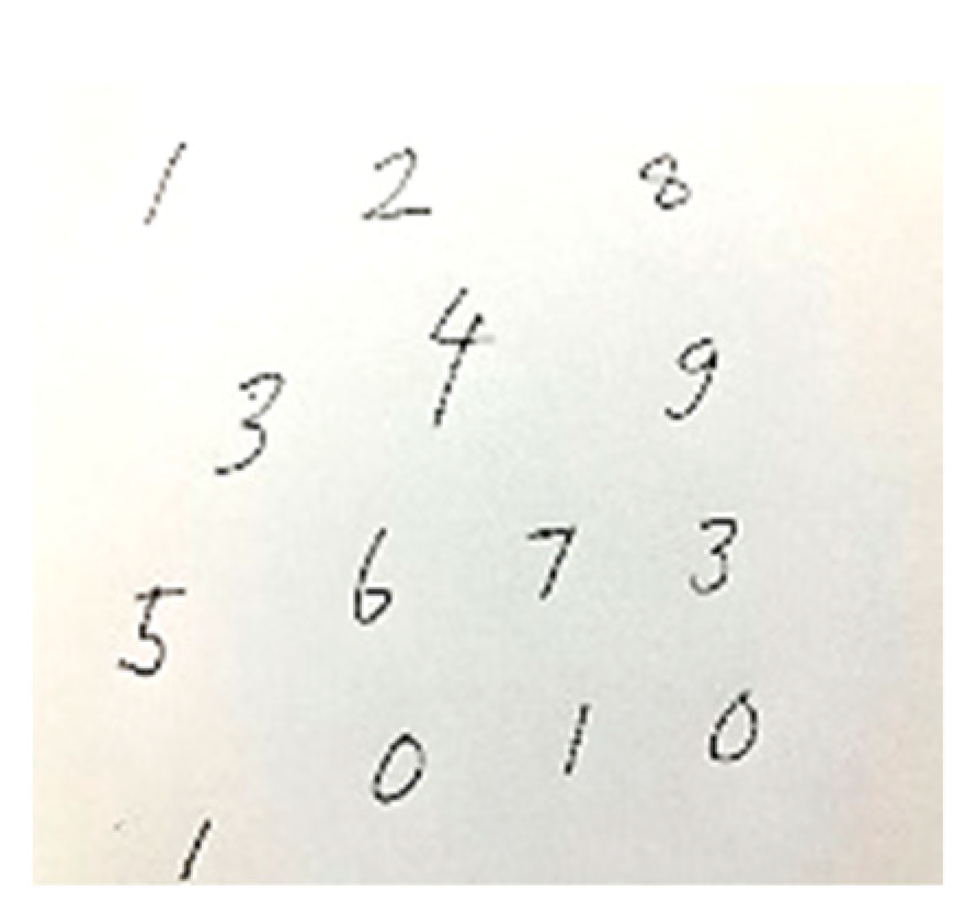
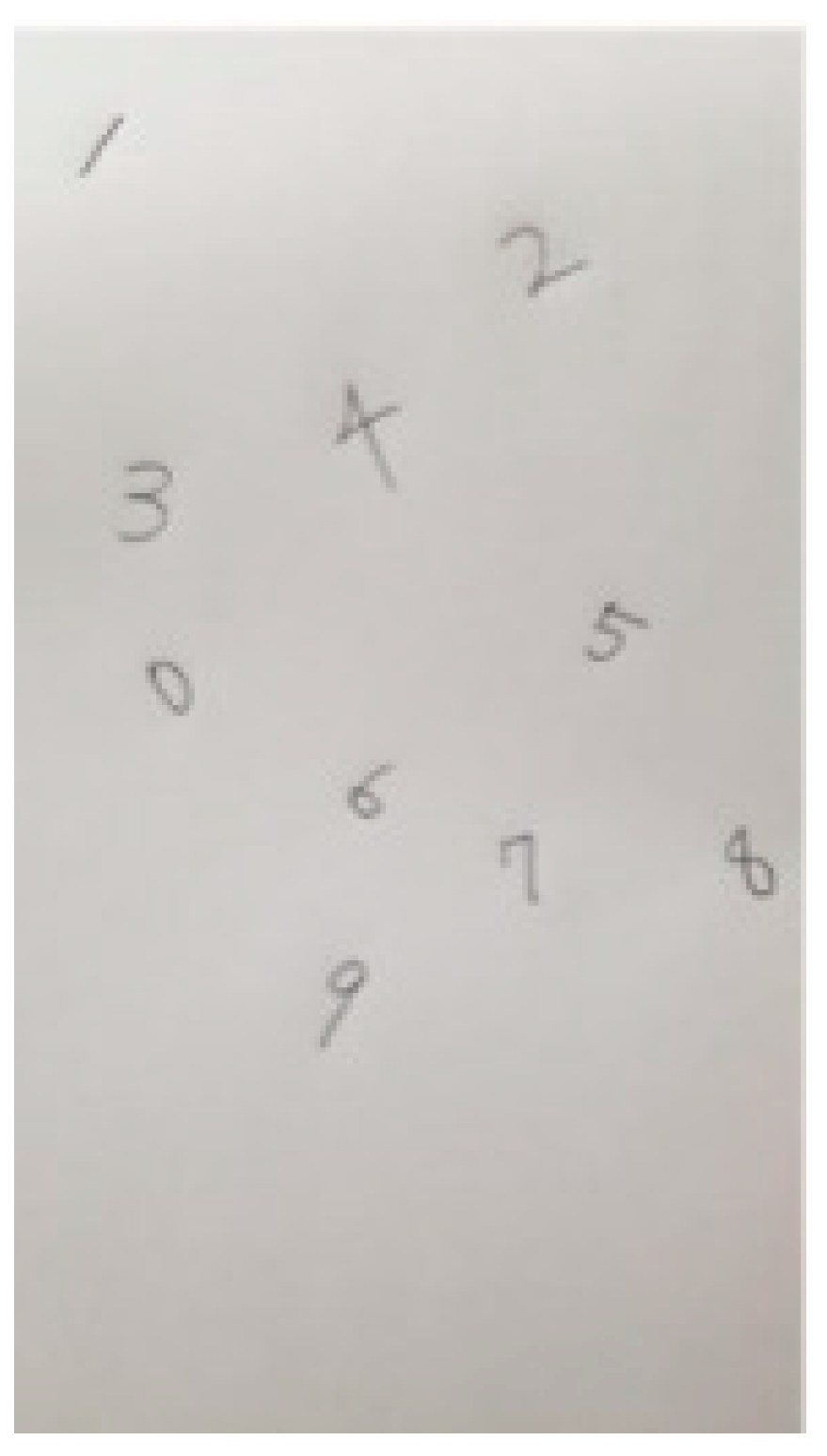
:1. Introduction
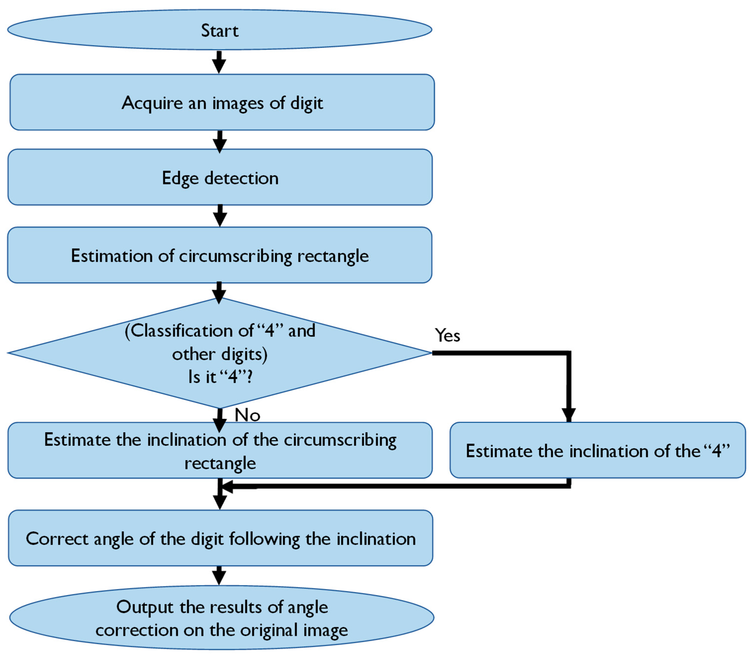
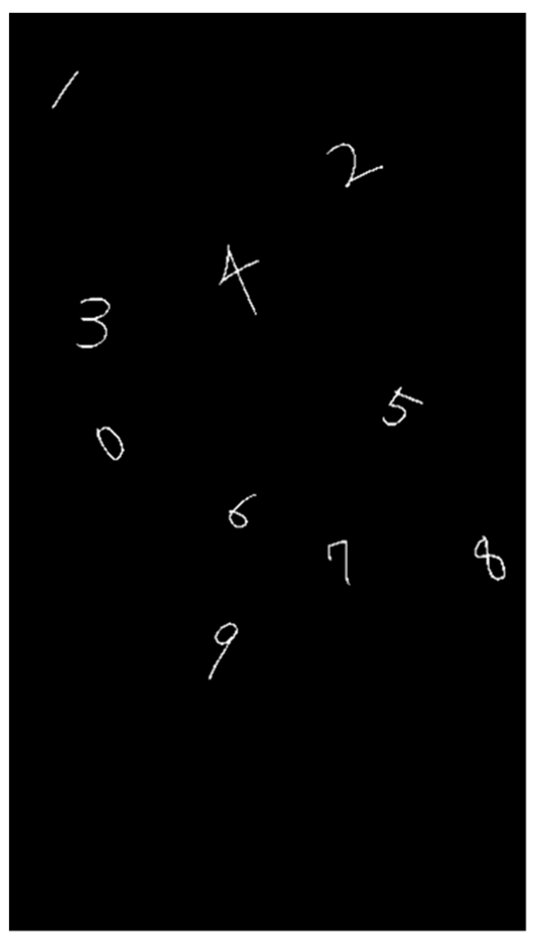
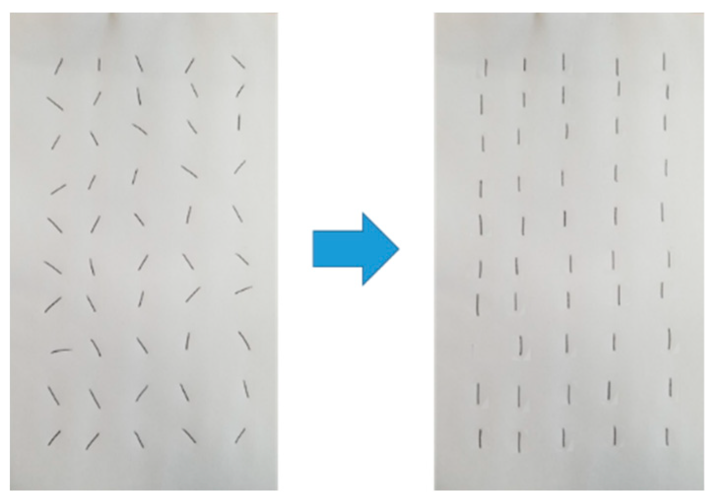
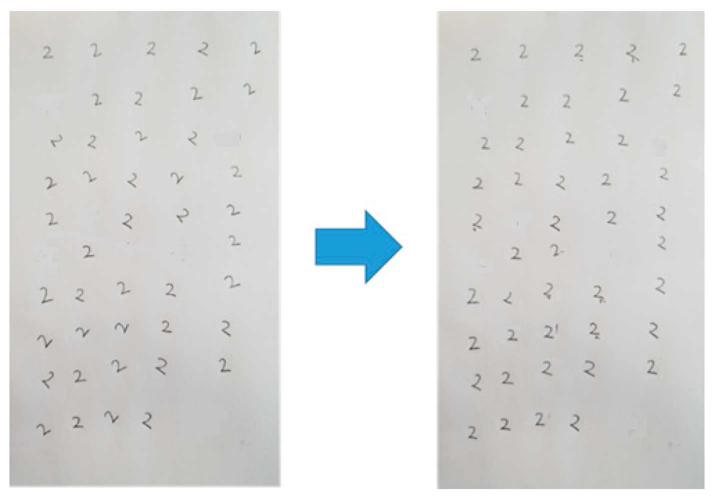
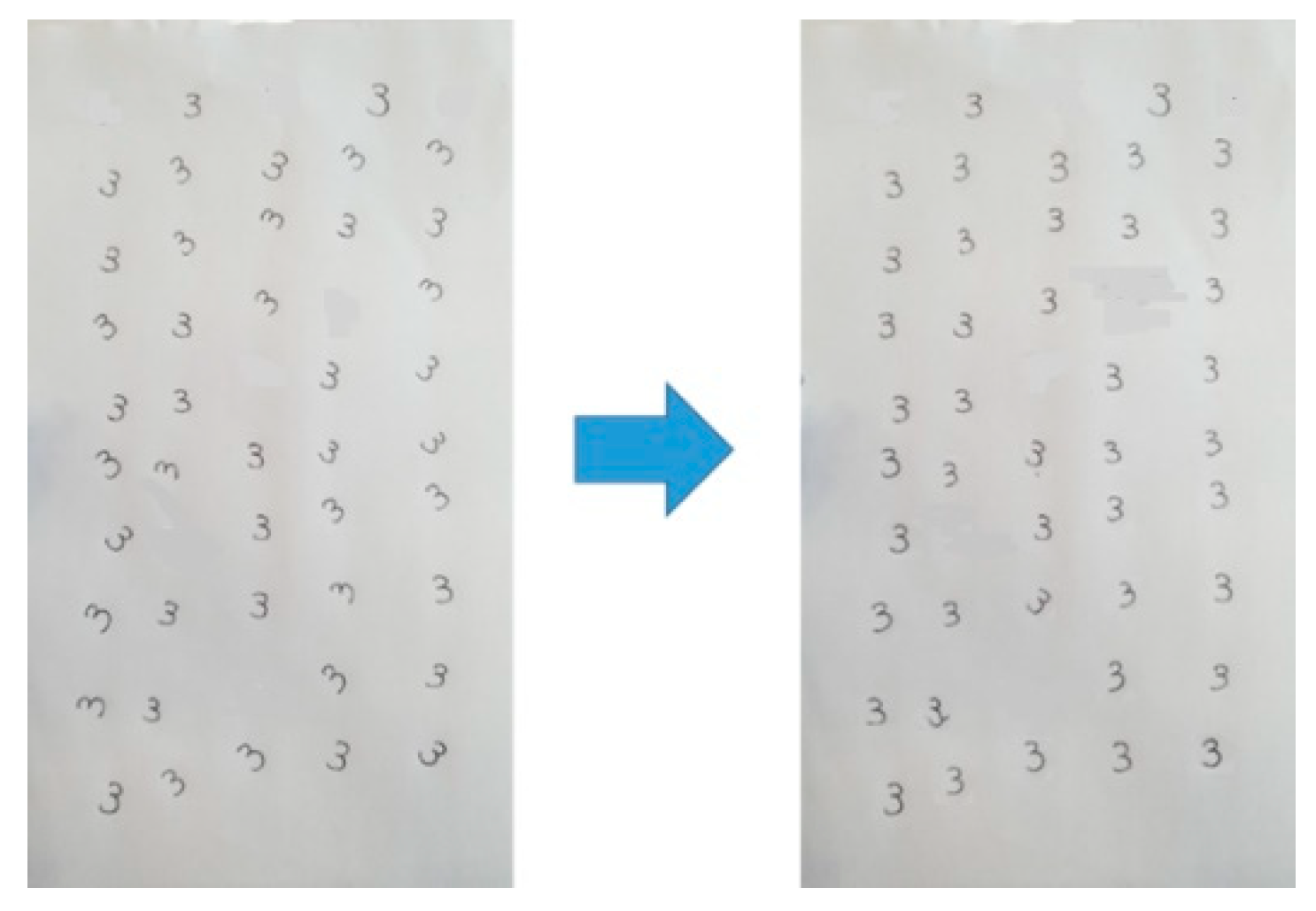
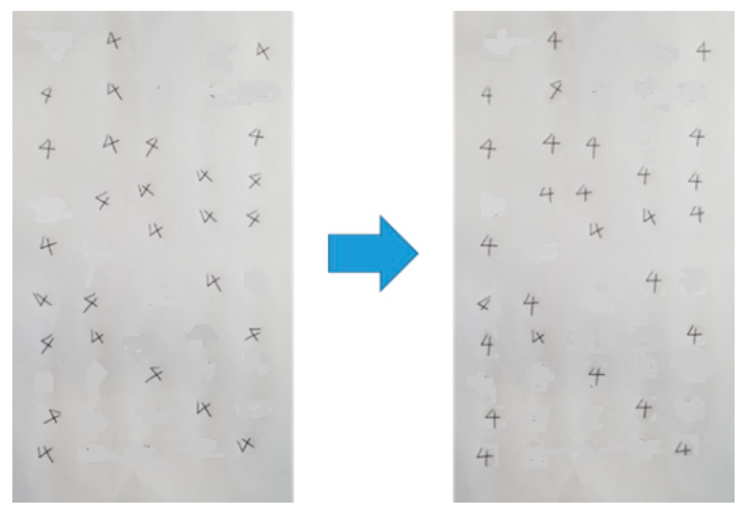
2. Tilt Estimation and Correction
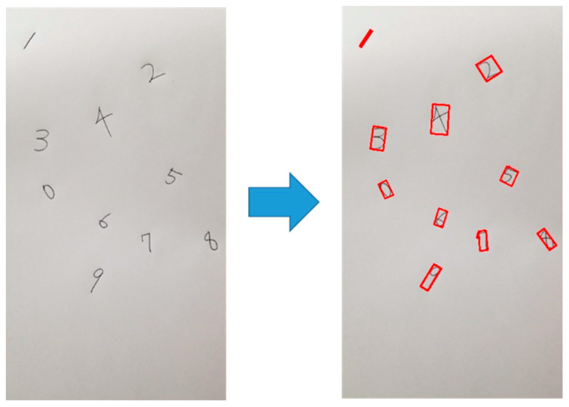
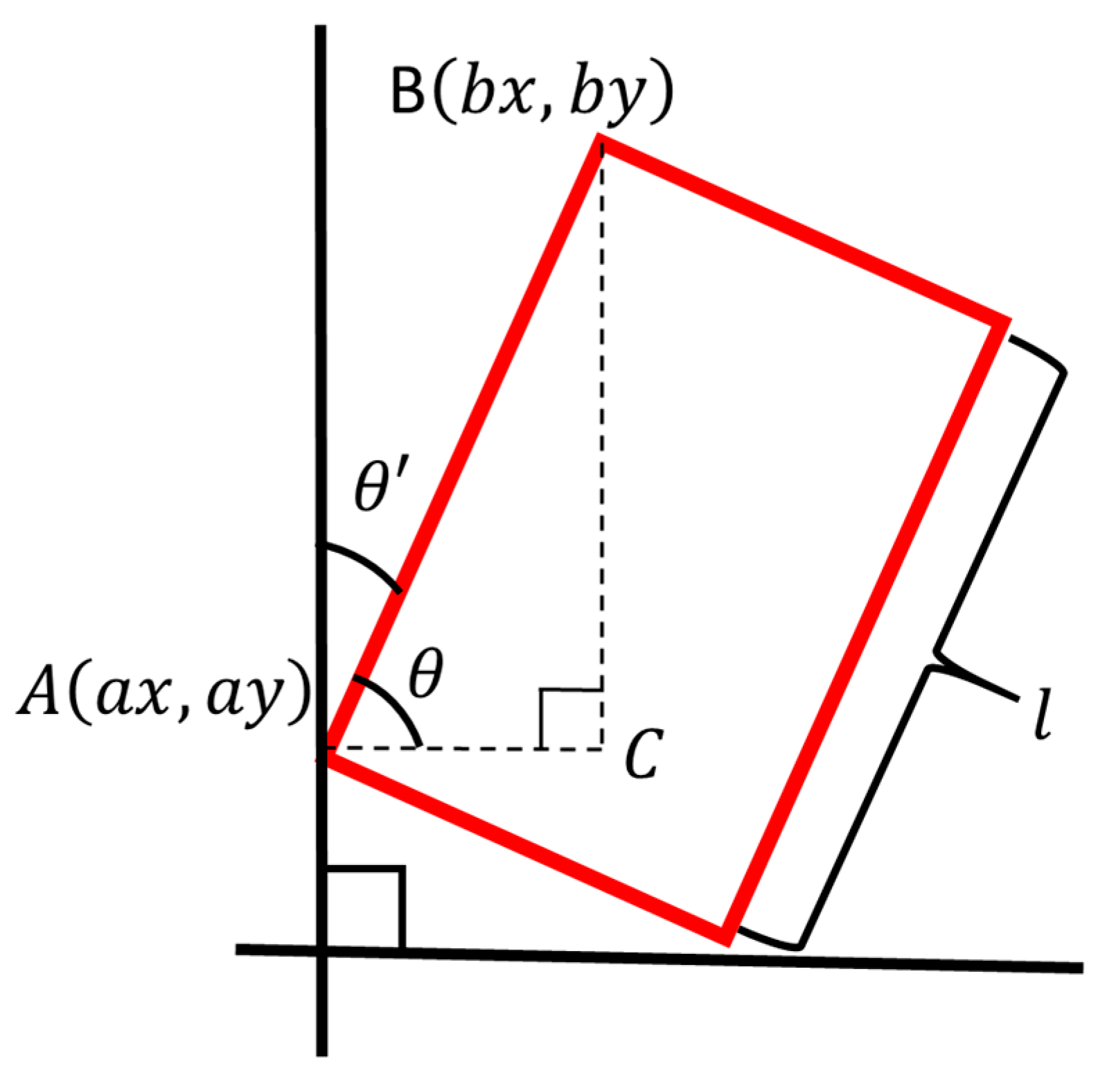
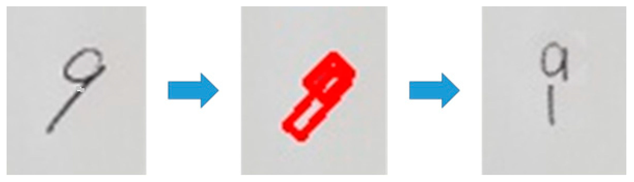
2.1. Tilt Estimation with the Circumscribed Rectangle
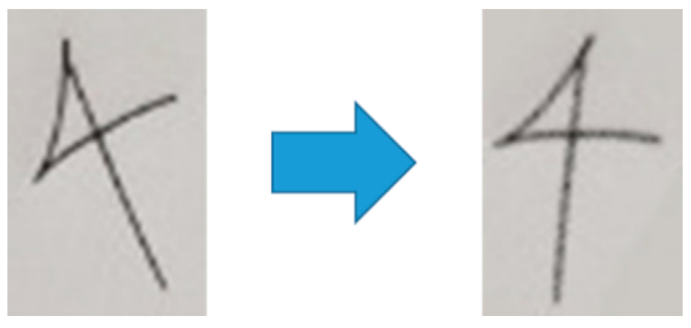
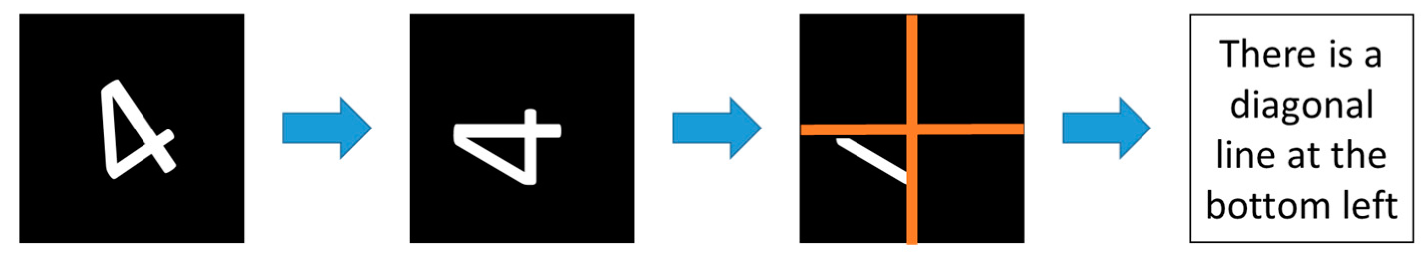
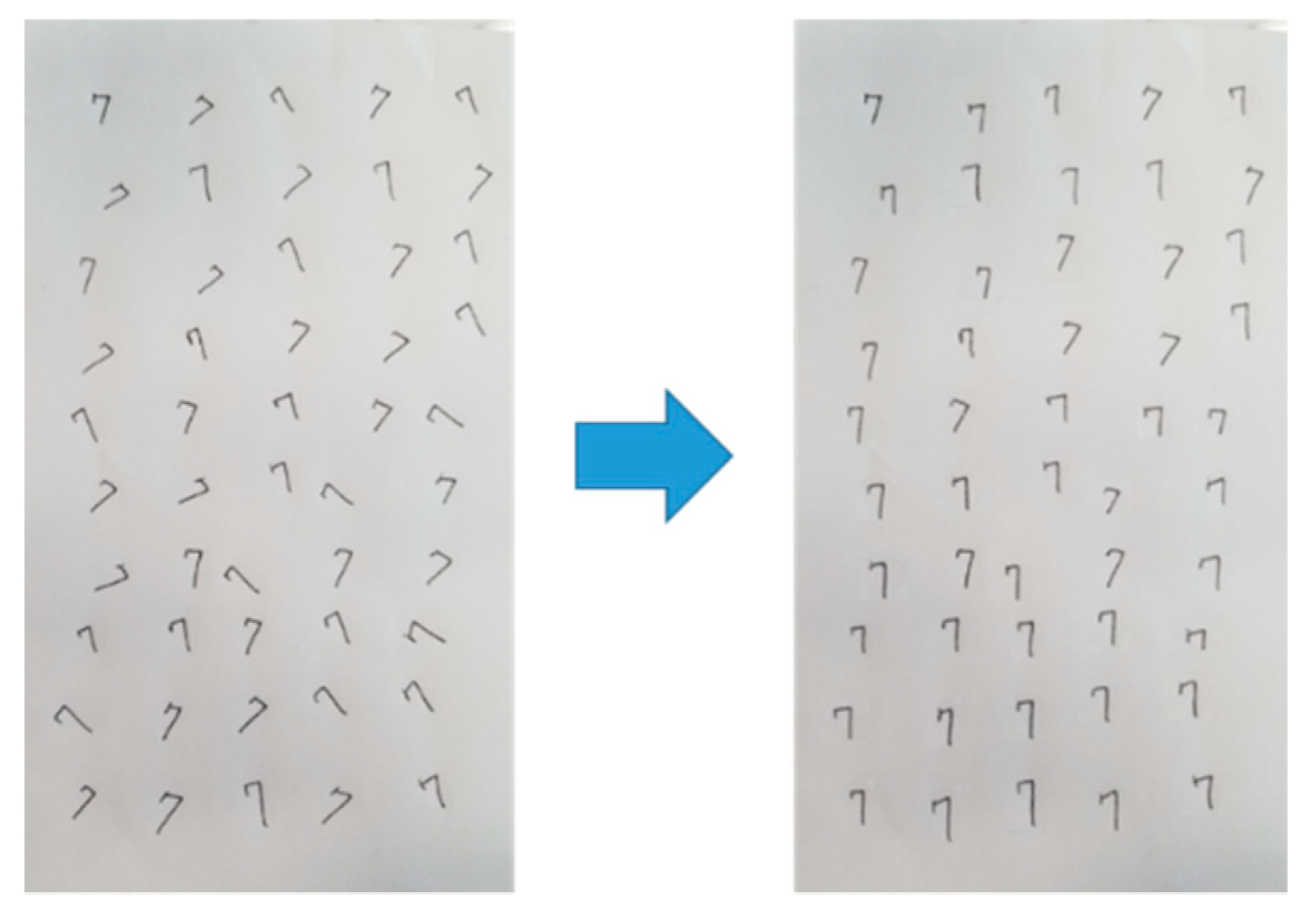
2.2. Separation of “4” and other Digits
2.3. Tilt Estimation of “4”
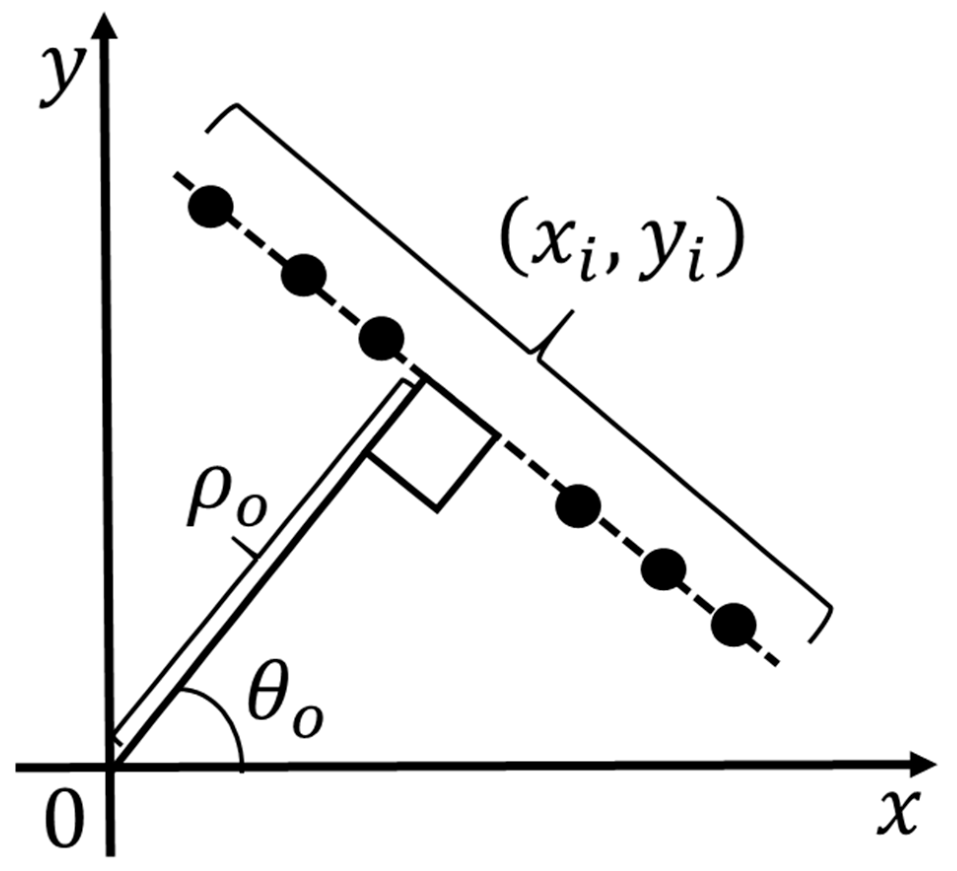
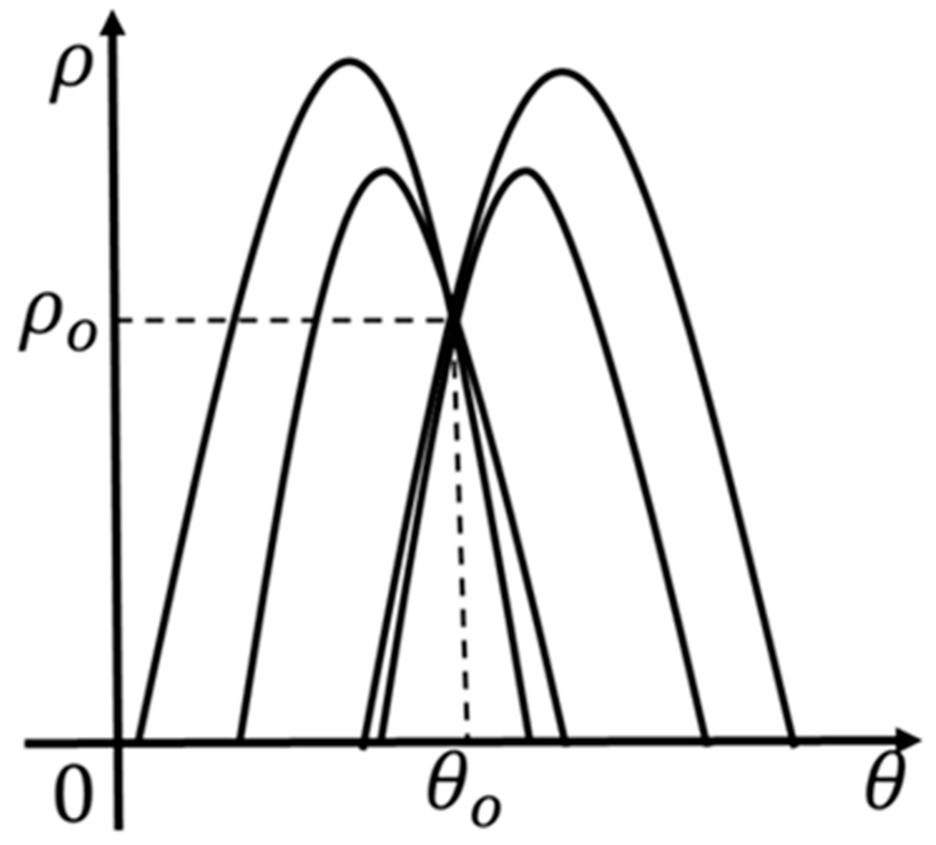
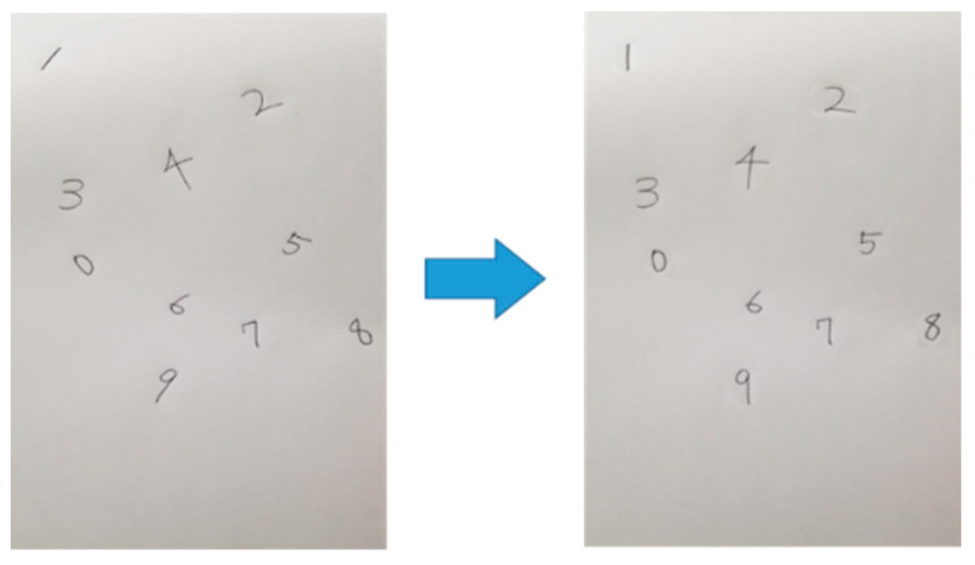
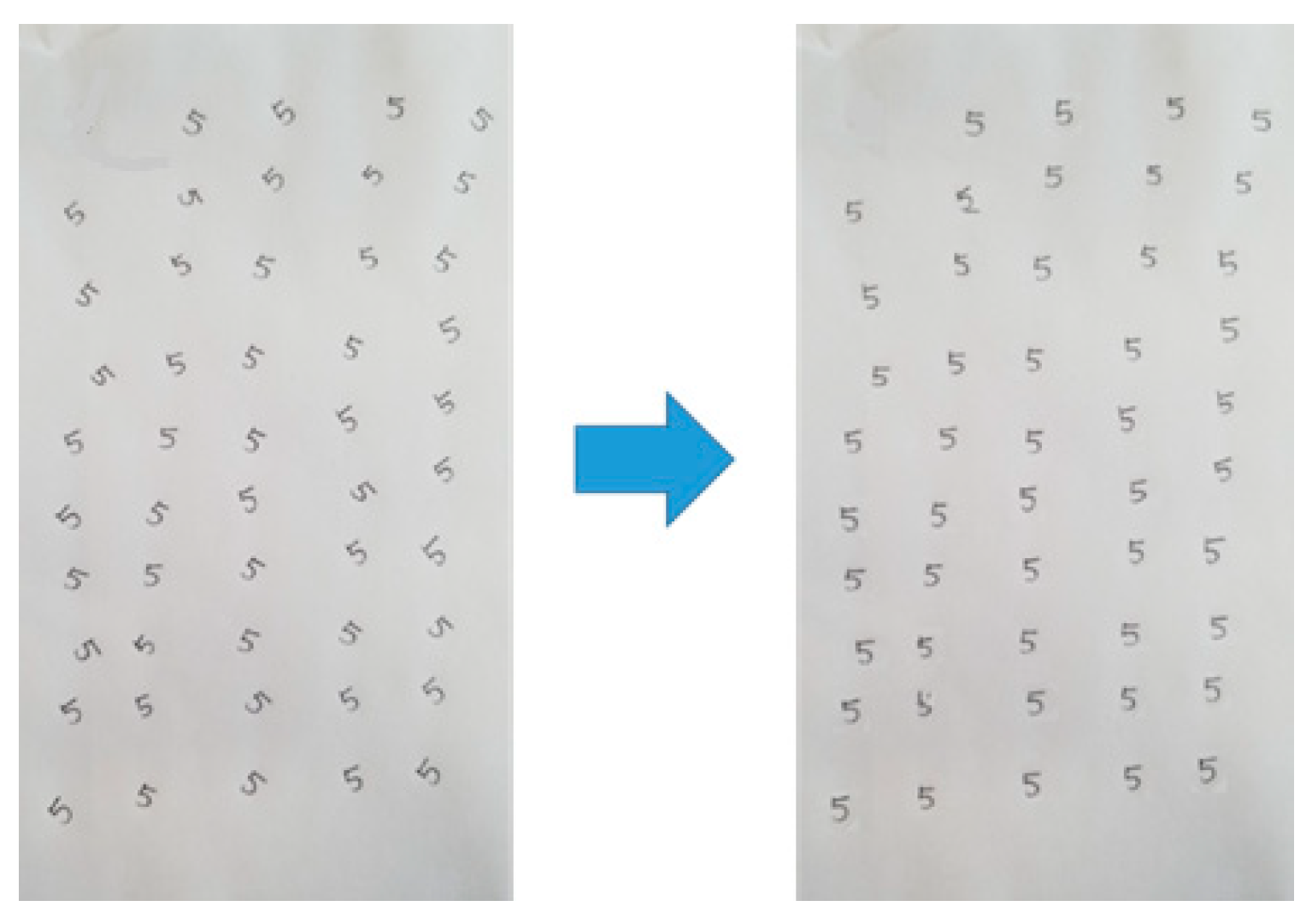
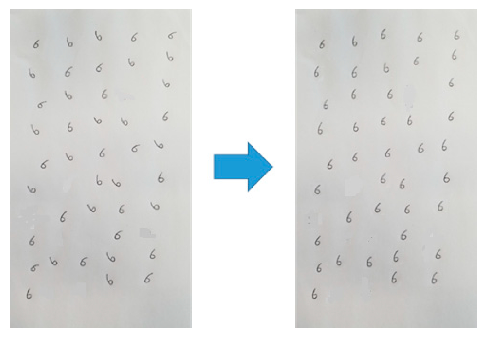
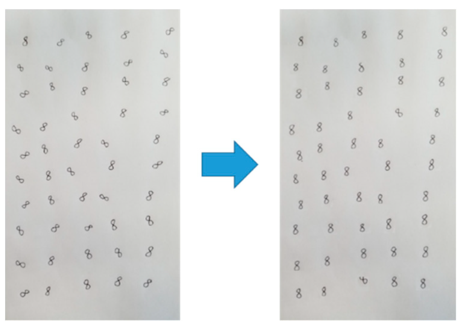
3. Tilt Correction
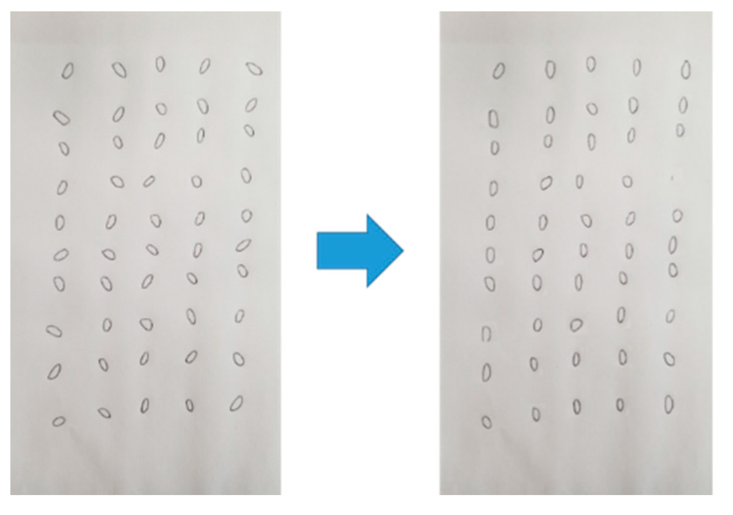
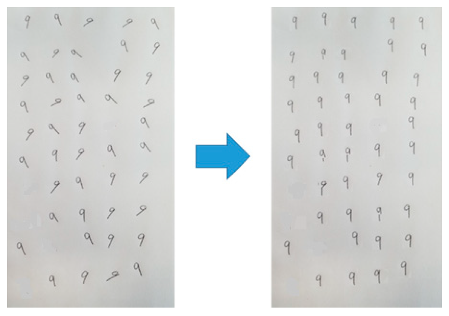
4. Experimental Evaluations
4.1. Experimental Environment
4.2. Experimental Results
5. Conclusions
Author Contributions
Funding
Conflicts of Interest
References
- Wang, J.-R.; Chuang, Y.-Y. Shadow Removal of Text Document Images by Estimating Local and Global Background Colors. In Proceedings of the 2020 IEEE International Conference on Acoustics, Speech and Signal Processing (ICASSP), Barcelona, Spain, 4–8 May 2020; pp. 1534–1538. [Google Scholar]
- Brown, M.S.; Tsoi, Y.-C. Geometric and shading correction for images of printed materials using boundary. IEEE Trans. Image Process. 2006, 15, 1544–1554. [Google Scholar] [CrossRef] [PubMed]
- Mtimet, J.; Amiri, H. Document class recognition using a support vector machine approach. In Proceedings of the 2016 2nd International Conference on Advanced Technologies for Signal and Image Processing (ATSIP), Monastir, Tunisia, 21–23 March 2016; pp. 161–166. [Google Scholar]
- Sreelakshmi, U.K.; Akash, V.G.; Rani, N.S. Detection of variable regions in complex document images. In Proceedings of the 2017 International Conference on Communication and Signal Processing, Melmaruvathur, India, 6–8 April 2017. [Google Scholar]
- Garg, R.; Chaudhury, S. Automatic Selection of Parameters for Document Image Enhancement Using Image Quality Assessment. In Proceedings of the 2016 12th IAPR Workshop on Document Analysis Systems, Santorini, Greece, 11–14 April 2016; pp. 422–427. [Google Scholar]
- Kieu, V.; Visani, M.; Journet, N.; Mullot, R.; Domenger, J. An efficient parametrization of character degradation model for semi-syntheticimage generation. In Proceedings of the Workshop on Historical Document Imaging and Processing, Washington, DC, USA, 24 August 2013. [Google Scholar]
- El-Etriby, S.S.; Amin, K.M. Detection and correction of deformed historical arabic manuscripts. In Proceedings of the International Conference on Computer and Communication Engineering (ICCCE’10), Kuala Lumpur, Malaysia, 22–23 June 2021. [Google Scholar]
- Wang, J.; Du, J.; Zhang, J.; Wang, Z.-R. Multi-modal Attention Network for Handwritten Mathematical Expression Recognition. In Proceedings of the 2019 International Conference on Document Analysis and Recognition (ICDAR), Sydney, Australia, 20–25 September 2019; pp. 1181–1186. [Google Scholar]
- Papandreou, A.; Gatos, B. A Coarse to Fine Skew Estimation Technique for Handwritten Words. In Proceedings of the 2013 12th International Conference on Document Analysis and Recognition, Washington, DC, USA, 25–28 August 2013; pp. 225–229. [Google Scholar]
- Vinciarelli, A.; Luettin, J. A new normalization technique for cursive handwritten words. Pattern Recognit. Lett. 2001, 22, 1043–1050. [Google Scholar] [CrossRef] [Green Version]
- Premachandra, C.; Goto, K.; Tsuruoka, S.; Kawanaka, H.; Takase, H. Speedy Character Line Detection Algorithm using Image Block-Based Histogram Analysis. In Proceedings of the Lecture Notes in Computer Science, Aachen, Germany, 4 July 2015; Volume 9164, pp. 481–488. [Google Scholar] [CrossRef]
- Goto, K.; Premachandra, C.; Tsuruoka, S.; Takase, H.; Kawanaka, H. Fast algorithm for character line extraction from handwritten examination papers. In Proceedings of the 2014 Joint 7th International Conference on Soft Computing and Intelligent Systems (SCIS) and 15th International Symposium on Advanced Intelligent Systems (ISIS), Kitakyushu, Japan, 3–6 December 2014; pp. 1454–1458. [Google Scholar]
- de Neto, S.A.F.; Bezerra, B.L.D.; Toselli, A.H.; Lima, E.B. A Handwritten Text Recognition System Based on a Pipeline of Optical and Language Models. In Proceedings of the ACM Symposium on Document Engineering 2020, Virtual, 29 September–1 October 2020; pp. 1–4. [Google Scholar]
- Neto, A.; Bezerra, B.; Toselli, A. Towards the Natural Language Processing as Spelling Correction for Offline Handwritten Text Recognition Systems. Appl. Sci. 2020, 10, 7711. [Google Scholar] [CrossRef]
- Neto, A.F.D.S.; Bezerra, B.L.D.; Lima, E.B.; Toselli, A.H. HDSR-Flor: A Robust End-to-End System to Solve the Handwritten Digit String Recognition Problem in Real Complex Scenarios. IEEE Access 2020, 8, 208543–208553. [Google Scholar] [CrossRef]
- Nagai, A. On the Improvement of Recognizing Single-Line Strings of Japanese Historical Cursive. In Proceedings of the 2019 International Conference on Document Analysis and Recognition (ICDAR), Sydney, Australia, 20–25 September 2019; pp. 621–628. [Google Scholar]
- Kieu, V.-C.; Stutzmann, D.; Vincent, N. Vacuity Measure for Handwritten Character Analysis. In Proceedings of the 2017 14th IAPR International Conference on Document Analysis and Recognition (ICDAR), Boston, MA, USA, 9–11 June 2010; pp. 561–566. [Google Scholar]
- Hao, Y.; Zhu, B.; Nakagawa, M. Large Improvement in Line-Direction-Free and Character-Orientation-Free On-Line Handwritten Japanese Text Recognition. In Proceedings of the 2014 14th International Conference on Frontiers in Handwriting Recognition, Crete Island, Greece, 1–4 September 2014; pp. 329–334. [Google Scholar]
- Campos, V.B.; Gómez, V.R.; Rossi, A.H.T.; Ruiz, E.V. Text Line Extraction Based on Distance Map Features and Dynamic Programming. In Proceedings of the 2018 16th International Conference on Frontiers in Handwriting Recognition (ICFHR), Niagara Falls, NY, USA, 5–8 August 2018; pp. 357–362. [Google Scholar]
- Dutta, A.; Garai, A.; Biswas, S.; Das, A.K. Segmentation of text lines using multi-scale CNN from warped printed and handwritten document images. Int. J. Doc. Anal. Recognit. (IJDAR) 2021, 24, 299–313. [Google Scholar] [CrossRef]
- Bonyani, M.; Jahangard, S.; Daneshmand, M. Persian handwritten digit, character and word recognition using deep learning. Int. J. Doc. Anal. Recognit. (IJDAR) 2021, 24, 133–143. [Google Scholar] [CrossRef]
- Otsu, N. A threshold selection method from gray-level histograms. IEEE Trans. Syst. Man Cybern. 1979, 9, 62–66. [Google Scholar] [CrossRef] [Green Version]
- Canny, J. A computational approach to edge detection. IEEE Trans. Pattern Anal. Mach. Intell. 1986, 8, 679–698. [Google Scholar] [CrossRef] [PubMed]
- Zhou, P.; Ye, W.; Wang, Q. An Improved Canny Algorithm for Edge Detection. J. Comput. Inf. Syst. 2011, 7, 1516–1523. [Google Scholar]
- Mallat, S.; Zhong, S. Characterization of Signals from Multi scale Edges. IEEE Trans. Pattern Anal. Mach. Intell. 1992, 14, 710–732. [Google Scholar] [CrossRef] [Green Version]
- Deng, G.; Wu, Y. Double Lane Line Edge Detection Method Based on Constraint Conditions Hough Transform. In Proceedings of the 2018 17th International Symposium on Distributed Computing and Applications for Business Engineering and Science (DCABES), Wuxi, China, 19–23 October 2018; pp. 107–110. [Google Scholar]
- Nasseri, M.H.; Moradi, H.; Nasiri, S.; Hosseini, R. Power Line Detection and Tracking Using Hough Transform and Particle Filter. In Proceedings of the 2018 6th RSI International Conference on Robotics and Mechatronics (IcRoM), Tehran, Iran, 23–25 October 2018; pp. 130–134. [Google Scholar]
- Premachandra, H.W.H.; Premachandra, C.; Parape, C.D.; Kawanaka, H. Speed-up ellipse enclosing character detection approach for large-size document images by parallel scanning and Hough transform. Int. J. Mach. Learn. Cybern. 2017, 8, 371–378. [Google Scholar] [CrossRef]
- Ishida, Y.; Izuoka, H.; Chinthaka, H.; Premachandra, N.; Kato, K. A study on plane extraction from distance images using 3D Hough transform. In Proceedings of the 6th International Conference on Soft Computing and Intelligent Systems, and the 13th International Symposium on Advanced Intelligence Systems, Kobe, Japan, 20–24 November 2012; pp. 812–816. [Google Scholar]
- Premachandra, C.; Gohara, R.; Kato, K. Fast lane boundary recognition by a parallel image processor. In Proceedings of the 2016 IEEE International Conference on Systems, Man, and Cybernetics (SMC), Budapest, Hungary, 9–12 October 2016. [Google Scholar]
- Vladimir, T.; Dongwoon, J.; Kim, D.H. Hough Transform with Kalman Filter on GPU for Real-Time Line Tracking. In Proceedings of the Seventh International Conference on Innovative Mobile and Internet Services in Ubiquitous Computing, Taichung, Taiwan, 3–5 July 2013; pp. 212–216. [Google Scholar]
- Fernandes, L.A.F.; Oliveira, M.M. Real-time line detection through an improved Hough transformvoting scheme. Pattern Recognit. 2008, 41, 299–314. [Google Scholar] [CrossRef]
- Belokurov, V. Implementation of affine transform for image rotation using a HLS language. In Proceedings of the 2018 7th Mediterranean Conference on Embedded Computing (MECO), Budva, Montenegro, 10–14 June 2018; pp. 1–4. [Google Scholar]
- Sazaki, Y.; Putra, S. Implementation of Affine Transform Method and Advanced Hill Cipher for securing digital images. In Proceedings of the 10th International Conference on Telecommunication Systems Services and Applications (TSSA), Bali, Indonesia, 6–7 October 2016. [Google Scholar]
- Ono, S.; Premachandra, C. Generation of Panoramic Images by Two Hemispherical Cameras Independent of Installation Location. IEEE Consum. Electron. Mag. 2020, 11, 17–25. [Google Scholar] [CrossRef]
- Kusetogullari, H.; Yavariabdi, A.; Cheddad, A.; Grahn, H.; Hall, J. ARDIS: A Swedish historical handwritten digit dataset. Neural Comput. Appl. 2020, 32, 16505–16518. [Google Scholar] [CrossRef] [Green Version]
- Kusetogullari, H.; Yavariabdi, A.; Hall, J.; Lavesson, N. DIGITNET: A Deep Handwritten Digit Detection and Recognition Method Using a New Historical Handwritten Digit Dataset. Big Data Res. 2021, 23, 100182. [Google Scholar] [CrossRef]
- Cheddad, A.; Kusetogullari, H.; Hilmkil, A.; Sundin, L.; Yavariabdi, A.; Aouache, M.; Hall, J. SHIBR—The Swedish Historical Birth Records: A semi-annotated dataset. Neural Comput. Appl. 2021, 33, 15863–15875. [Google Scholar] [CrossRef]
- Lins, R.D.; Bernardino, R.B.; Smith, E.B.; Kavallieratou, E. ICDAR 2021 Competition on Time-Quality Document Image Binarization. In Document Analysis and Recognition—ICDAR 2021. ICDAR 2021. Lecture Notes in Computer Science; Lladós, J., Lopresti, D., Uchida, S., Eds.; Springer: Cham, Switzerland, 2021. [Google Scholar] [CrossRef]


| Number | Success Rate of Inclination Correction (%) |
|---|---|
| 0 | 96 |
| 1 | 100 |
| 2 | 92 |
| 3 | 91 |
| 4 | 86 |
| 5 | 93 |
| 6 | 91 |
| 7 | 92 |
| 8 | 95 |
| 9 | 90 |
| Number | Success Rate of Inclination Correction (%) |
|---|---|
| 0 | 97 |
| 1 | 99 |
| 2 | 94 |
| 3 | 93 |
| 4 | 90 |
| 5 | 93 |
| 6 | 92 |
| 7 | 93 |
| 8 | 97 |
| 9 | 94 |
| Number | Success Rate of Classification (%) |
|---|---|
| 0 | 98 |
| 1 | 100 |
| 2 | 95 |
| 3 | 94 |
| 5 | 97 |
| 6 | 93 |
| 7 | 93 |
| 8 | 90 |
| 9 | 91 |
| Number | Success Rate of Inclination Correction (%) |
|---|---|
| 0 | 99 |
| 1 | 100 |
| 2 | 97 |
| 3 | 96 |
| 4 | 92 |
| 5 | 95 |
| 6 | 96 |
| 7 | 96 |
| 8 | 98 |
| 9 | 95 |
Publisher’s Note: MDPI stays neutral with regard to jurisdictional claims in published maps and institutional affiliations. |
© 2022 by the authors. Licensee MDPI, Basel, Switzerland. This article is an open access article distributed under the terms and conditions of the Creative Commons Attribution (CC BY) license (https://creativecommons.org/licenses/by/4.0/).
Share and Cite
Premachandra, H.W.H.; Yamada, M.; Premachandra, C.; Kawanaka, H. Low-Computational-Cost Algorithm for Inclination Correction of Independent Handwritten Digits on Microcontrollers. Electronics 2022, 11, 1073. https://doi.org/10.3390/electronics11071073
Premachandra HWH, Yamada M, Premachandra C, Kawanaka H. Low-Computational-Cost Algorithm for Inclination Correction of Independent Handwritten Digits on Microcontrollers. Electronics. 2022; 11(7):1073. https://doi.org/10.3390/electronics11071073
Chicago/Turabian StylePremachandra, H. Waruna H., Maika Yamada, Chinthaka Premachandra, and Hiroharu Kawanaka. 2022. "Low-Computational-Cost Algorithm for Inclination Correction of Independent Handwritten Digits on Microcontrollers" Electronics 11, no. 7: 1073. https://doi.org/10.3390/electronics11071073