Article

The Characteristics of the Second and Third Virtual Cathodes in an Axial Vircator for the Generation of High-Power Microwaves

1
Electrical and Biological Physics, Kwangwoon University, Seoul 01897, Republic of Korea
2
Plasma Bioscience Research Center (PBRC), Kwangwoon University, Seoul 01897, Republic of Korea
*
Author to whom correspondence should be addressed.
Electronics 2022, 11(23), 3973; https://doi.org/10.3390/electronics11233973
Submission received: 29 October 2022 / Revised: 16 November 2022 / Accepted: 28 November 2022 / Published: 30 November 2022
(This article belongs to the Special Issue Advanced RF, Microwave Engineering, and High-Power Microwave Sources)

Abstract

:
A virtual cathode oscillator or vircator is a vacuum tube for producing high-power microwaves (HPM). The efficiency of the vircator has been a difficult task for decades. The main reasons for low efficiency are intense relativistic electron beam (IREB) loss and few or no interactions between IREB and HPM. In this case, forming multiple virtual cathodes may be beneficial in overcoming these constraints. By reusing the axially propagating leaked electrons (LE), we could confine them and form multiple virtual cathodes (VCs). This article discussed the characteristics of newly formed VCs based on simulation results. The formation time of new VCs was discovered to be highly dependent on the reflector position and the density of LE approaching their surfaces. Furthermore, multiple VC formation in the waveguide region does not affect conventional VCs’ position or forming time. The emission mode of the generated HPM was TM01 with single and multiple VCs and remained unaffected. The formation of multiple VCs positively influenced the axial and radial electric fields. When compared to a single VC, the axial and radial electric field increased 25.5 and 18 times with multiple VCs. The findings suggested that forming multiple VCs could be a future hope for achieving high vircator efficiency.

1. Introduction

Microwaves have become an essential component of modern life [1]. When a microwave’s peak power approaches 100 MW or beyond, it is referred to as high-power microwave (HPM) [2]. HPMs are used in various existing tasks in science and technology. Many HPM devices are associated with contemporary scientific fields, such as ion acceleration, plasma heating, and thermonuclear fusion. In addition to pure fundamental science, HPM sources are of great commercial interest for radars, communications, power beaming, and other space applications [3,4,5,6]. In recent years, HPM has given rise as a new technology that enables new applications and breakthroughs in existing ones [6]. Armed services, communication, satellite tracking, linear colliders, accelerators, friction heating, astronomy, and medicine are a few key sectors where microwave radiation has a significant impact [7,8,9]. Microwaves have numerous medical applications [9,10,11,12,13]. Due to the increasing applications of HPM, humans are exposed to these radiations regularly. As a result, the biological effects of these radiations have become an important topic of active research [14,15,16,17,18]. Nearly every day, the popularity of HPM grows, and organizations are looking for more efficient HPM sources. As a result, improving the efficiency of HPM sources is an important and active area of research.
Multiple HPM sources are available to fulfill the demand, with the virtual cathode oscillator (vircator or VCO) emerging as the preferred class of oscillator for producing HPM [19]. Vircators are a relatively simple method for extracting electromagnetic energy from intense relativistic electron beams (IREBs) and generating microwaves capable of providing high-power radiation up to a peak power reaching gigawatt levels, or for amplification of powerful microwave signals. Furthermore, VCO can function without an external magnetic field. It is also simple to construct and fully comprehend because it only has three primary components: cathode, anode, and virtual cathode (VC) [20].
Despite the fact that a VCO has many advantages, it is less efficient. In experiments, the conversion of IREB energy to electromagnetic radiation energy remained lower than 20% [20,21,22]. As a result, the improvement of VCO efficiency has remained an ongoing and open research area.
Many scientists are constantly working on this topic; various changes to standard VCO models have been aimed at increasing their microwave power and efficiency by employing effective methods [23,24,25,26,27,28,29,30,31,32]. It is critical to improve the production of HPMs in VCO by using different reflectors, resonators, and other electrodes, which positively affect microwave power, efficiency, mode conversion, and frequencies. To improve efficiency, Molchanov et al. simulated an axial vircator with three-cavity resonators [33]. A multistage axial VCO with multiple reflectors inside the waveguide was studied numerically and achieved 21% efficiency [34]. To increase the carrier modulation frequency and power, we should try to increase the IREB density in the VC region. In this regard, Alexander et al. proposed a coaxial conical electrode in the VCO to focus the IREB at the conventional VC (here: VC-1) region, and the kinetics of these electrons were numerically studied [35]. The results show that the frequency transitioned to a greater value, and the output power increased as well [35]. Implementing a longitudinal magnetic field is the most common technique for facilitating IREB movement in a straight direction in the downstream region of a waveguide [24,36]. Although this technique was found to be effective in this regard, the power and efficiency results show that the presence of an additional outer axial magnetic field in the waveguide region reduces VCO efficiency [24]. This occurs because the electrons’ holding time in VC-1 increased, lowering the peak power.
We assume the following key points of low efficiency here: the formation of a single VC that fails to confine all the transmitted IREB and causes electron loss in the form of leaking electrons (LE), and low or no interactions between electromagnetic radiations and IREB inside the device, as shown in Figure 1a. In this context, the formation of multiple VCs is the best alternative, as shown in Figure 1b. The emergence of multiple VCs in the downstream region provides substantial advantages over traditional VCO, which are as follows: The LE was reused and the IREB loss was significantly reduced, the interaction between the electromagnetic wave and the IREB was increased, as well as the power and frequency [30,37,38,39]. Previously, we successfully formed the second and third virtual cathodes (VC-2 and VC-3), also known as multiple VCs [40,41]. Previous research has not looked into the specific characteristics of multiple VCs. Additionally, the kinetic energy, formation time of each VC, radial and axial electric fields at each position, and microwave emission mode were not studied in our earlier experiments.
In this work, we extended our previous model [41], and investigated the characteristics of VC-2 and VC-3 and their influence on the VCO by using a three-dimensional (3D) particle-in-cell simulation code (PICSC). We investigated the IREB particle kinetic energy (KE) and formation time of VC-2 and VC-3. Furthermore, we examined the effects of changing multiple VCs’ positions on the axial electric field (AEF) and radial electric field (REF). The profiles of vector electric and vector magnetic fields from the simulation were used to investigate the emission mode of an axial VCO with single VC-1, two VCs, and three or multiple VCs. Finally, we presented the experimental results obtained by adjusting the multiple VCs to their best positions. The positions of several VCs were found to be related to the amplitude of AEF and REF. Additionally, both single and multiple VCs were found to have no effect on the emission mode.

2. Methodology

A 3D PICSC was used in the MAGIC software to simulate the positions of effects of multiple VCs. The IREB and device parameters were used similarly to our previous study [40]. The cathode diameter was 90 mm, and the anode was semitransparent foil with a diameter of 200 mm. The waveguide was 250 mm long with an inner diameter similar to anode foil. The LE was reused at two insulator reflectors’ surfaces as a wall charge. The first reflector (R-1) had a hole with a diameter of 40 mm, while the second reflector (R-2) was completely blocked. The reflectors were kept at a 10 mm thickness. First, the position of R-1 was moved from 60 mm to 180 mm with a step size of 20 mm using anode foil as a reference. After securing the R-1 in its optimal position of 100 mm, the R-2 was installed and moved away from the R-1 by 20 mm to 80 mm in 10 mm steps. The characteristics of multiple VCs were investigated at each reflector position. In a simulation, the IREB was released from the cathode using the explosive command. The Chundoong, whose parameters were previously explained [14,29,40,42], was used for experiments illustrated in Figure 2.

3. Results

3.1. Phase Space of IREB and Formation of Multiple VCs

Figure 3 shows the device structure in simulation and IREB profiles in the real VCO space with a single VC and with multiple VCs. At 0 ns (before beam emission), 2 ns (after beam emission), and 35 ns, the IREB behavior in real schematic space was recorded as shown in Figure 3a–c, respectively. In 3D PICSC, it is observed that the single VC does not cut off the IREB and that most of the electrons propagate along the waveguide and are lost at the conducting wall, resulting in electron loss in the form of LE. The LE was confined inside the interaction region when two reflectors R-1 and R-2 were located in the downstream region of the waveguide, as shown in Figure 3c,d before and after beam emission, respectively.
When the flowing IREB current exceeds the limiting current of the VCO device, the VC-1 is formed [2,38,43,44]. When the VC is formed, the KE of the electrons after passing through the anode foil drops to zero, which helps to identify the position of VC in simulation. In one of our earlier experiments, we used an experiment to determine the position of conventional VC [29]. The results of the experiment and the simulation were in good agreement. The simulation’s results can be trusted to support the validity of VCs. Simulated data are also used in other studies to locate the VC [35,39,44,45]. Figure 4 shows the results of the formation time and position of single and multiple VCs from the simulation. Figure 4a shows the KE of the IREB when only a single VC is formed. The position of VC-1 is almost 10 mm similar to the spacing kept between the anode and cathode. The findings show good agreement with the previous ones [29,42,44]. The formation time of the VCs was recorded when the KE of the electrons decreased to zero in the waveguide region. Figure 4c shows the formation time of VC-2 by changing the position of the first reflector R-1. When the position of R-1 was changed to 60 mm, 80 mm, 100 mm, 120 mm, and 140 mm, the formation time of the VC-2 was found to be 7 ns, 10.2 ns, 12.5 ns, 14 ns, and 15 ns, respectively. However, the VC-2 was not formed at distances 160 mm and 180 mm due to the lower LE density at the reflector surface. Figure 4d shows the formation time of VC-3 by changing the position of the second reflector R-2. It is observed that when the position of R-2 changed as 20 mm, 30 mm, 40 mm, 50 mm, and 60 mm, the VC-3 was formed at 12 ns, 13 ns, 15 ns, 15.1 ns, and 15.5 ns, respectively. Similarly, the VC-3 was not formed at 70 mm and 80 mm due to the low density of LE.

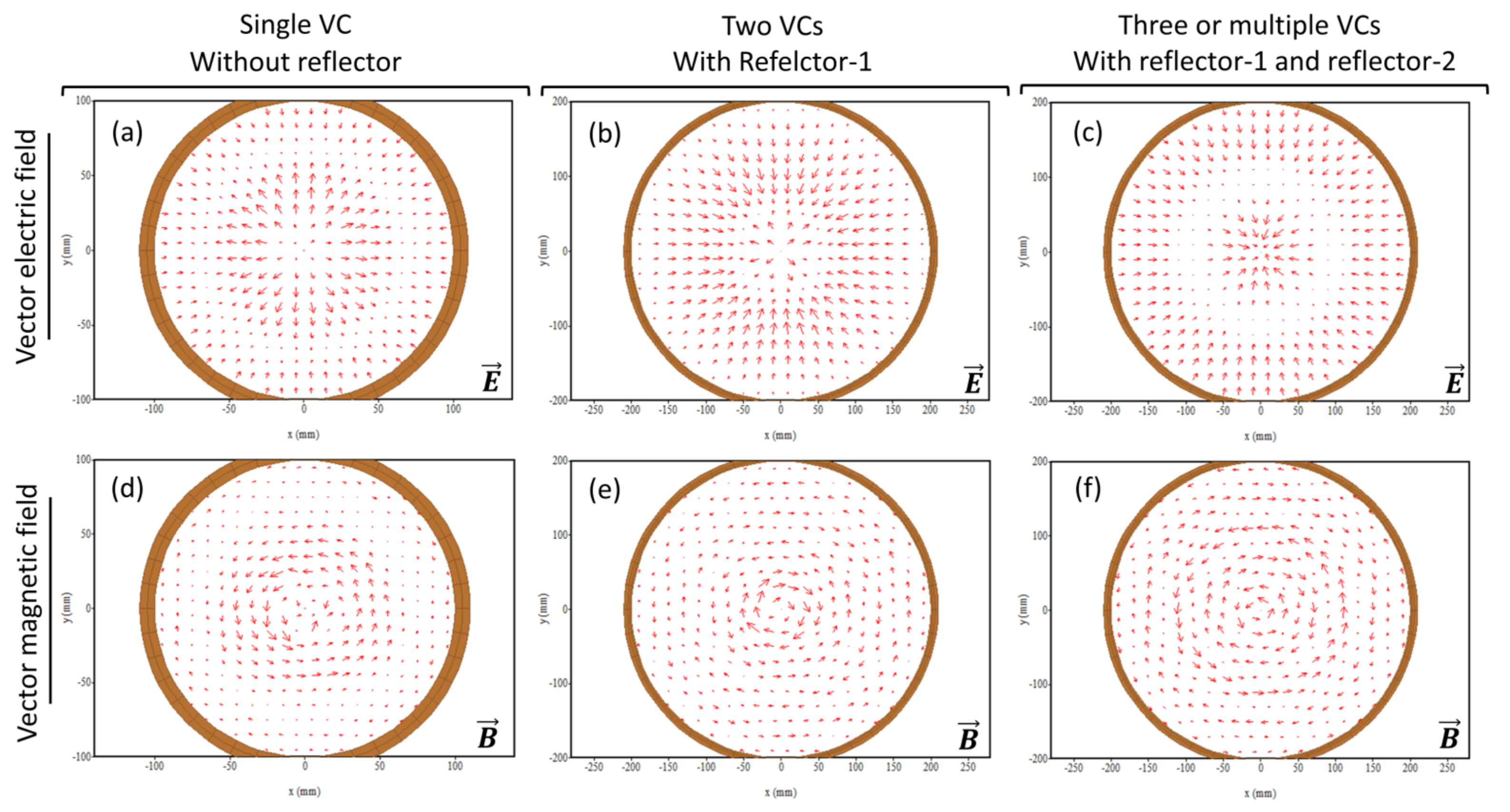
3.2. Influence of the Multiple VCs on the Axial and Radial Electric Fields

Figure 5 depicts the results of an investigation into the effect of multiple VCs on the AEF and REF in the 3D PICSC. The AEF and REF distribution of conventional VCO was shown in Figure S3. As it is seen in Figure 5a, the maximum AEF with a single VC-1 was 0.41 MW/V in a traditional axial VCO. When VC-2 was formed, the amplitude grew massively. The AEF amplitude was 3.2 MV/m, 3.7 MV/m, 4 MV/m, 3.73 MV/m, 2.1 MV/m, 0.5 MV/m, and 0.45 MV/m when the R-1 position was changed to 60 mm, 80 mm, 100 mm, 120 mm, and 140 mm, 160 mm, and 180 mm, respectively. At the best position of R-1, 100 mm, the AEF reaches its maximum value of 4 MV/m. Similarly, the REF also increased as 0.4 MV/m, 0.42 MV/m, 0.5 MV/m, 0.39 MV/m, 0.29 MV/m, 0.103 MV/m, and 0.101 MV/m, according to the respective positions of R-1. The REF reaches its maximum value of 0.5 MW/m at the prime location of R-1, which is also 100 mm, as shown in Figure 5b.
For further research into the effect of three or multiple VCs of AEF and REF, R-1 was fixed to its optimal conditions (R-1 fixed at 100 mm); only R-2 was moveable, and results are shown in Figure 5c,d. It is noted that the multiple VCs increased the amplitude of the AEF and REF even more. Figure 5c shows the AEF by changing the R-2 position. When the R-2 position was changed to 20 mm, 30 mm, 40 mm, 50 mm, 60 mm, 70 mm, and 80 mm, the AEF amplitude was 8.2 MV/m, 8.4 MV/m, 10.2 MV/m, 7.8 MV/m, 4.9 MV/m, 4.103 MV/m, and 4.101 MV/m, respectively. The AEF reaches its maximum value of 10.2 MV/m at the ideal position of R-2, which was 40 mm. Figure 5d depicts the REF as the R-2 position changes. The AEF amplitude was 1.45 MV/m, 1.5 MV/m, 1.8 MV/m, 1.2 MV/m, 1.17 MV/m, 0.5 MV/m, and 0.49 MV/m when the R-2 position was changed to 20 mm, 30 mm, 40 mm, 50 mm, 60 mm, 70 mm, and 80 mm, respectively. At the ideal position of R-2, which was 40 mm, the REF reaches its maximum value of 1.8 MV/m. Compared to a single VC, the AEF increased fourfold, and the REF increased fivefold with multiple VCs. The qualitative analysis of the microwave power, and quantitative analysis for frequency were also estimated in the simulation, and findings are given in the Supplementary Materials Figures S1 and S2.

3.3. Estimation of the Emission Mode with Single and Multiple-VCs

The electric vector field (VEF) and magnetic vector field (VMF) profiles were used to determine the HPM emission mode with a single VC and multiple VCs. The intensity and direction of the vector fields observed in the simulation are depicted in Figure 6. Three-dimensional PICSC was used to obtain vector field profiles at the waveguide end. Figure 6a–c depicts the VEF profiles, while (d–f) depicts the VMF profiles. The arrow length indicates the intensity, while the arrowhead indicates the direction of the VEF and VMF. Figure 6a depicts the VEF obtained when a single VC is formed without reflectors. Figure 6b shows the VEF with two VCs when the first reflector (R-1) was installed at the optimal position of 100 mm from the anode. Figure 6c shows the VEF when three or multiple VCs are formed, and both reflectors R-1 (100 mm away from anode) and R-2 (40 mm away from R-1) were optimally positioned inside the waveguide region. Respectively, Figure 6d–f shows the VMF with a single VC, two VCs, and three or multiple VCs. Due to the axial vibration of VCs in the axial VCO, the dominant mode was found to be TM, from which particularly TM01 dominant. The proposed work’s results were found to be in agreement with earlier findings obtained through experiments and 3D PICS [38,40,42,44]. Furthermore, the emission mode of the HPM remained almost unchanged with the formation of multiple VCs with reflectors.

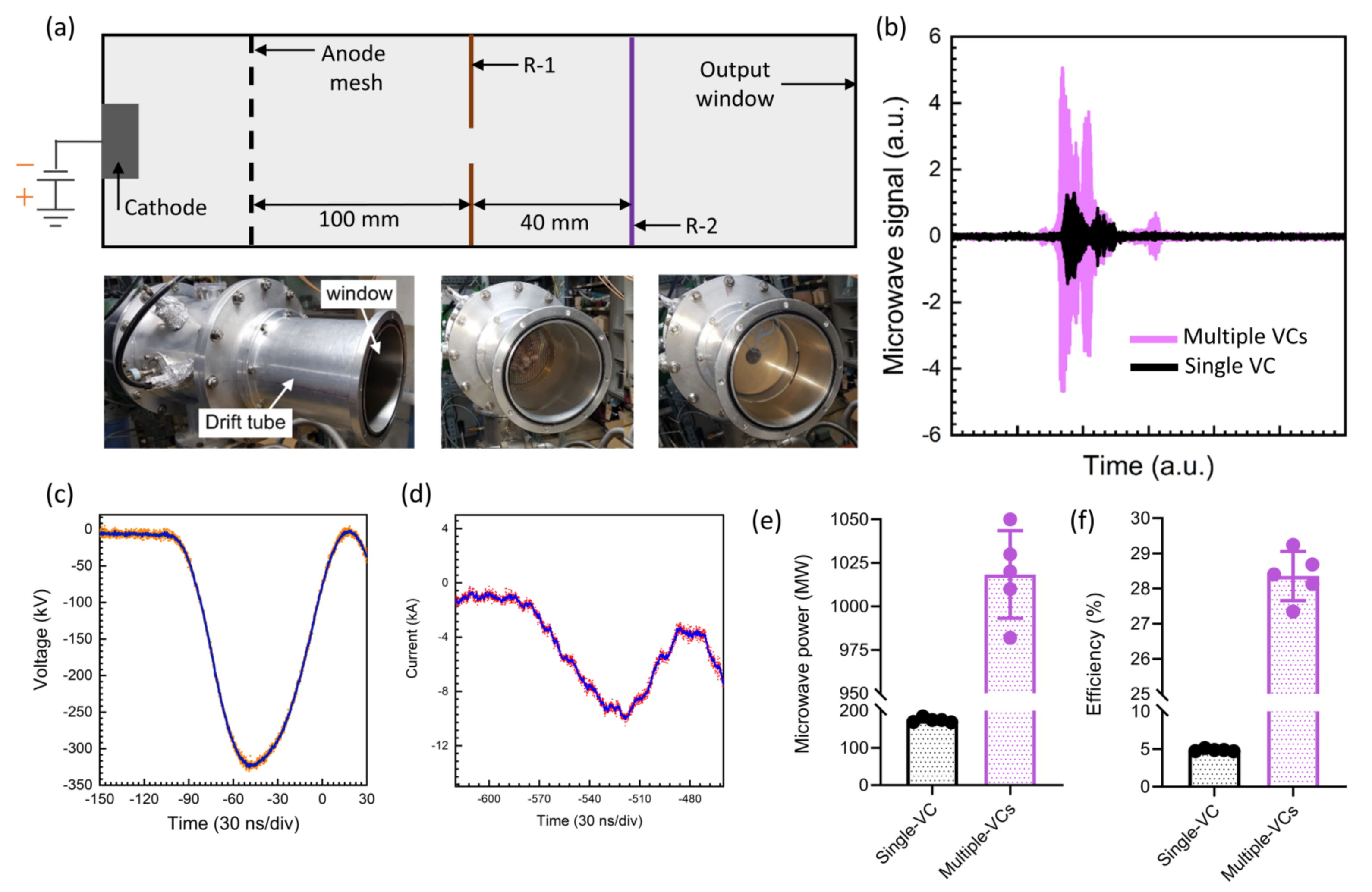
3.4. Output Power and Efficiency Comparison of Axial VCO with Single-VC and Multiple-VCs

Figure 7 depicts the results of the experiment. Figure 7a shows a schematic of a modified waveguide with two reflectors installed, and Figure 7b shows photographs of the waveguide before and after introducing additional insulating reflectors (R-1 and R-2) inside the waveguide downstream area. Figure 7c shows the measured average microwave real signal obtained in the experiment. It is observed that the amplitude of the HPM was significantly increased with multiple VCs when compared with a single VC. Figure 7d shows the diode voltage waveform reaching a maximum of 343 kV. Figure 7e is the diode current waveform obtained during the experiment with a maximum value of 10.52 kA. Figure 7f compares microwave power with a single VC to microwave power with multiple VCs, which is the average of five HPM pulses when both reflectors are installed in their ideal positions (R-1 at 100 mm from the anode, and R-2 is 40 mm from the first reflector). The microwave power obtained with a conventional single VC was 175 MW, which was significantly increased to a maximum of 1020 MW with multiple VCs. Figure 7g depicts the device efficiency, nearly 5%, with a single VC; however, it improved to almost 28% with multiple VCs.

4. Discussion

The VCO or vircator is a vacuum tube used to generate HPM. The formation of multiple VCs in axial VCO might be a future hope to obtain high efficiency from this device. In the simulation, up to 10 VCs were successfully formed in a recent study [39]. Even though the simulation shows progress, the devices’ complex structures remained challenging to implement in real experiments. This work gives the advantage of forming multiple VCs by a simple structure, adding two insulator reflectors downstream of the region of the waveguide. The reusing of the LE significantly decreased the loss of IREB, and also played a vital role to strengthen the interaction region [45,46].
The output power and frequency are dependent on the geometrical vircator components [2,42,47,48,49]. The amount of IREB particles (electrons) that can make it through to the waveguide region largely depends on the anode’s transparency. A higher HPM output and less electron loss at the anode are caused by higher anode transmission ratios, according to studies [50]. When the density of IREB in the interaction region increased, the output power of HPM increased and the frequency shifted [38,41].
A multistage axial VCO with multiple reflectors inside the waveguide was numerically studied recently and found to be 21% efficient [34]. Increasing the IREB density in the VC region is critical to increasing the carrier modulation frequency and power. A longitudinal magnetic field is the most traditional procedure for facilitating IREB movement in a straight direction to avoid electron loss. However, subsequent research discovered that supplying an outer external magnetic field reduces the peak power of the HPM, resulting in a decrease in device efficiency [24,51]. The simulation shows that the electrons’ phase space momentum and KE were reduced to zero in the downstream region (Figure 3), which corresponds to the positions of newly formed VCs. When the LE was reflected in the interaction region by forming multiple VCs, it increased the amplitude of the AEF and REF, as shown in Figure 4. The increased amplitude of AEF and REF leads to the enhancement of the output power of HPM, which is observed in the experiment and compared with conventional VCO (Figure 7). Reducing the LE loss without applying a magnetic field in this study might be useful and there is future hope to design high-efficiency VCOs.

5. Conclusions

The VCO is an excellent device for generating HPM. For decades, improving the vircator’s efficiency has been a difficult task. The primary causes of low efficiency are IREB loss and a lack of interrelationships between IREB and microwaves. In this case, forming multiple virtual cathodes could help overcome these constraints. By forming multiple VCs, we could confine the LE in the interaction region [41]. In this work, we examined the characteristics and boundaries of multiple VCs, the KE particle of IREB, the formation time of each VC, and their influence on the electric field and emission mode of HPM. The results indicate that multiple VCs do not influence traditional VCs’ position and formation time. The formation time and position depending on the position of the reflectors. The multiple VCs greatly influenced the amplitude of AEF and REF. Multiple VCs increased the AEF by 25.5 times and REF by 18 times compared to a single VC. Furthermore, the HPM emission mode with single and multiple VCs was noticed as TM01 and remained unchanged. The experiments also demonstrate that multiple VCs massively increase the microwave output power and improves the device efficiency from 5% to 28%. The findings suggested that forming multiple VCs could be a future hope for achieving high VCO efficiency.

Supplementary Materials

The following supporting information can be downloaded at: https://www.mdpi.com/article/10.3390/electronics11233973/s1.

Author Contributions

Conceptualization, S.M.; methodology, S.M.; software, S.M.; validation, S.M. and E.-H.C.; formal analysis, S.M.; investigation, S.M.; resources, S.M.; data curation, S.M.; writing—original draft preparation, S.M.; writing—review and editing, S.M. and E.-H.C.; visualization, S.M. and E.-H.C.; supervision, E.-H.C.; project administration, S.M. and E.-H.C.; funding acquisition, E.-H.C. All authors have read and agreed to the published version of the manuscript.

Funding

This work was supported in part by the National Research Foundation of Korea (NRF) Grant through the Korean Government under Grant NRF-2022R1A2C1004257 and Grant NRF-2021R1A6A1A03038785, and by ITRC (Information Technology Research Center) support program (IITP-2020-0-01846), also by the Excellent researcher support project of Kwangwoon University in 2022.

Data Availability Statement

The data presented in this study are available from the corresponding author upon request.

Conflicts of Interest

The authors declare no conflict of interest.

References

  1. Vendik, I.B.; Vendik, O.G. Metamaterials and their application in microwaves: A review. Tech. Phys. 2013, 58, 1–24. [Google Scholar] [CrossRef]
  2. Benford, J.; Swegle, J.A.; Schamiloglu, E. High Power Microwaves, 3rd ed.; Taylor & Francis: New York, NY, USA, 2016. [Google Scholar]
  3. Gold, S.H.; Nusinovich, G.S. Review of high-power microwave source research. Rev. Sci. Instrum. 1997, 68, 3945–3974. [Google Scholar] [CrossRef]
  4. Kumar, N.; Singh, U.; Singh, T.P.; Sinha, A.K. A Review on the Applications of High Power, High Frequency Microwave Source: Gyrotron. J. Fusion Energy 2011, 30, 257–276. [Google Scholar] [CrossRef]
  5. Dubinov, A.E.; Kornilova, I.Y.; Selemir, V.D. Collective ion acceleration in systems with a virtual cathode. Physics-Uspekhi 2002, 45, 1109–1129. [Google Scholar] [CrossRef]
  6. Benford, J. Space Applications of High-Power Microwaves. IEEE Trans. Plasma Sci. 2008, 36, 569–581. [Google Scholar] [CrossRef]
  7. Ramos, L.B.; Sánchez, R.J.; De Figueiredo, A.K.; Nolasco, S.M.; Fernández, M.B. Optimization of Microwave Pretreatment Variables for Canola Oil Extraction. J. Food Process Eng. 2017, 40, e12431. [Google Scholar] [CrossRef]
  8. Bakhshabadi, H.; Mirzaei, H.; Ghodsvali, A.; Jafari, S.M.; Ziaiifar, A.M.; Farzaneh, V. The effect of microwave pretreatment on some physico-chemical properties and bioactivity of Black cumin seeds’ oil. Ind. Crops Prod. 2017, 97, 1–9. [Google Scholar] [CrossRef]
  9. Grenier, K.; Dubuc, D.; Chen, T.; Artis, F.; Chretiennot, T.; Poupot, M.; Fournié, J. Recent Advances in Microwave-Based Dielectric Spectroscopy at the Cellular Level for Cancer Investigations. IEEE Trans. Microw. Theory Tech. 2013, 61, 2023–2030. [Google Scholar] [CrossRef] [Green Version]
  10. Tabuse, K. Basic knowledge of a microwave tissue coagulator and its clinical applications. J. Hepatobiliary Pancreat. Surg. 1998, 5, 165–172. [Google Scholar] [CrossRef]
  11. Vrba, J. Medical Applications of Microwaves. Electromagn. Biol. Med. 2005, 24, 441–448. [Google Scholar] [CrossRef]
  12. Han, I.; Mumtaz, S.; Ashokkumar, S.; Yadav, D.K.; Choi, E.H. Review of Developments in Combating COVID-19 by Vaccines, Inhibitors, Radiations, and Nonthermal Plasma. Curr. Issues Mol. Biol. 2022, 44, 384. [Google Scholar] [CrossRef] [PubMed]
  13. Jang, J.H.; Mumtaz, S.; Lee, S.W.; Kim, D.-Y.; Lim, J.S.; Kaushik, N.K.; Choi, E.H. Focus of high-power microwaves with positive and negative zone plate to increase the receiving power in axial virtual cathode oscillator. Curr. Appl. Phys. 2021, 29, 89–96. [Google Scholar] [CrossRef]
  14. Mumtaz, S.; Rana, J.N.; Choi, E.H.; Han, I. Microwave Radiation and the Brain: Mechanisms, Current Status, and Future Prospects. Int. J. Mol. Sci. 2022, 23, 9288. [Google Scholar] [CrossRef] [PubMed]
  15. Mumtaz, S.; Bhartiya, P.; Kaushik, N.; Adhikari, M.; Lamichhane, P.; Lee, S.-J.; Kaushik, N.K.; Choi, E.H. Pulsed high-power microwaves do not impair the functions of skin normal and cancer cells in vitro: A short-term biological evaluation. J. Adv. Res. 2020, 22, 47–55. [Google Scholar] [CrossRef]
  16. Bhartiya, P.; Mumtaz, S.; Lim, J.S.; Kaushik, N.; Lamichhane, P.; Nguyen, L.N.; Jang, J.H.; Yoon, S.H.; Choi, J.J.; Kaushik, N.K.; et al. Pulsed 3.5 GHz high power microwaves irradiation on physiological solution and their biological evaluation on human cell lines. Sci. Rep. 2021, 11, 8475. [Google Scholar] [CrossRef]
  17. Shaw, P.; Kumar, N.; Mumtaz, S.; Lim, J.S.; Jang, J.H.; Kim, D.; Sahu, B.D.; Bogaerts, A.; Choi, E.H. Evaluation of non-thermal effect of microwave radiation and its mode of action in bacterial cell inactivation. Sci. Rep. 2021, 11, 14003. [Google Scholar] [CrossRef]
  18. Yoon, S.; Jeong, K.; Mumtaz, S.; Choi, E.H. Electromagnetic pulse shielding effectiveness of circular multi-waveguides for fluids. Results Phys. 2020, 16, 102946. [Google Scholar] [CrossRef]
  19. Jiang, W.; Masugata, K.; Yatsui, K. Mechanism of microwave generation by virtual cathode oscillation. Phys. Plasmas 1995, 2, 982–986. [Google Scholar] [CrossRef]
  20. Jiang, W.; Dickens, J.; Kristiansen, M. Efficiency enhancement of a coaxial virtual cathode oscillator. IEEE Trans. Plasma Sci. 1999, 27, 1543–1544. [Google Scholar] [CrossRef]
  21. Biswas, D.; Kumar, R. Efficiency Enhancement of the Axial VIRCATOR. IEEE Trans. Plasma Sci. 2007, 35, 369–378. [Google Scholar] [CrossRef]
  22. Sullivan, D.J. High Power Microwave Generation from a Virtual Cathode Oscillator (Vircator). IEEE Trans. Nucl. Sci. 1983, 30, 3426–3428. [Google Scholar] [CrossRef]
  23. Badarin, A.A.; Kurkin, S.A.; Andreev, A.V.; Koronovskii, A.A.; Frolov, N.S.; Hramov, A.E. Virtual cathode oscillator with elliptical resonator. In Proceedings of the 2017 Eighteenth International Vacuum Electronics Conference (IVEC), London, UK, 24–26 April 2017; pp. 1–2. [Google Scholar]
  24. Jiang, W.; Kitano, H.; Huang, L.; Masugata, K.; Yatsui, K. Effect of longitudinal magnetic field on microwave efficiency of virtual cathode oscillator. IEEE Trans. Plasma Sci. 1996, 24, 187–192. [Google Scholar] [CrossRef]
  25. Dang, F. A new compact self-coherent high power microwave source based on dual beams. Phys. Plasmas 2015, 22, 053301. [Google Scholar] [CrossRef]
  26. Gurnevich, E.; Molchanov, P. The Effect of the Electron-Beam Parameter Spread on Microwave Generation in a Three-Cavity Axial Vircator. IEEE Trans. Plasma Sci. 2015, 43, 1014–1017. [Google Scholar] [CrossRef] [Green Version]
  27. Singh, G.; Chaturvedi, S. Particle-in-cell simulations for virtual cathode oscillator including foil ablation effects. Phys. Plasmas 2011, 18, 063104. [Google Scholar] [CrossRef]
  28. Chen, Y.; Mankowski, J.; Walter, J.; Kristiansen, M.; Gale, R. Cathode and Anode Optimization in a Virtual Cathode Oscillator. IEEE Trans. Dielectr. Electr. Insul. 2007, 14, 1037–1044. [Google Scholar] [CrossRef]
  29. Mumtaz, S.; Lim, J.S.; Ghimire, B.; Lee, S.W.; Choi, J.J.; Choi, E.H. Enhancing the power of high power microwaves by using zone plate and investigations for the position of virtual cathode inside the drift tube. Phys. Plasmas 2018, 25, 103113. [Google Scholar] [CrossRef]
  30. Mumtaz, S.; Munnaf, S.A.; Choi, E.H. Numerical study on the formation of second virtual cathode by using different material floating zone plate inside drift tube region. In Proceedings of the 2021 22nd International Vacuum Electronics Conference (IVEC), Virtual Conference, 27–30 April 2021; pp. 1–2. [Google Scholar]
  31. Kim, S.-H.; Lee, C.-J.; Kim, W.-I.; Ko, K.-C. Experimental Investigation into the Optimum Position of a Ring Reflector for an Axial Virtual Cathode Oscillator. Electronics 2021, 10, 1878. [Google Scholar] [CrossRef]
  32. Mohammadi Shirkolaei, M. A New Design Approach of Low-Noise Stable Broadband Microwave Amplifier Using Hybrid Optimization Method. IETE J. Res. 2020. [Google Scholar] [CrossRef]
  33. Molchanov, P.V.; Gurnevich, E.A.; Tikhomirov, V.V.; Siahlo, S.E. Simulation of an axial vircator with a three-cavity resonator. arXiv 2014, arXiv:1408.1824. [Google Scholar]
  34. Champeaux, S.; Gouard, P.; Cousin, R.; Larour, J. Improved design of a multistage axial vircator with reflectors for enhanced performances. IEEE Trans. Plasma Sci. 2016, 44, 31–38. [Google Scholar] [CrossRef]
  35. Dubinov, A.E.; Tarakanov, V.P. PIC Simulation of the Dynamics of Electrons in a Conical Vircator. IEEE Trans. Plasma Sci. 2016, 44, 1391–1395. [Google Scholar] [CrossRef]
  36. Kurkin, S.A.; Hramov, A.E.; Koronovskii, A.A. Microwave radiation power of relativistic electron beam with virtual cathode in the external magnetic field. Appl. Phys. Lett. 2013, 103, 43507. [Google Scholar] [CrossRef] [Green Version]
  37. Mumtaz, S.; Chandra Adhikari, B.; Minin, I.V.; Minin, O.V.; Lamichhane, P.; Paneru, R.; Ha Choi, E. Particle in cell simulation for the power enhancement by forming the second virtual cathode in an axial vircator. Results Phys. 2021, 24, 104126. [Google Scholar] [CrossRef]
  38. Mumtaz, S.; Nguyen, L.N.; Uhm, H.; Lamichhane, P.; Lee, S.W.; Choi, E.H. A novel approach to form second virtual cathode by installing a floating zone plate inside the drift tube. Results Phys. 2020, 17, 103052. [Google Scholar] [CrossRef]
  39. Dubinov, A.E.; Saikov, S.K.; Tarakanov, V.P. Multivircator as a New Highly Effective Microwave Generator With Multiple Virtual Cathodes: Concept and PIC-Simulation. IEEE Trans. Plasma Sci. 2020, 48, 141–145. [Google Scholar] [CrossRef]
  40. Mumtaz, S.; Uhm, H.; Lim, J.S.; Choi, E.H. Output-power enhancement of vircator based on second virtual cathode formed by wall charge on a dielectric reflector. IEEE Trans. Electron Devices 2022, 69, 2043–2050. [Google Scholar] [CrossRef]
  41. Mumtaz, S.; Choi, E.H. An Efficient Vircator with High Output Power and Less Drifting Electron Loss by Forming Multivirtual Cathodes. IEEE Electron Device Lett. 2022, 43, 1756–1759. [Google Scholar] [CrossRef]
  42. Mumtaz, S.; Lamichhane, P.; Sup Lim, J.; Ho Yoon, S.; Hyun Jang, J.; Doyoung, K.; Woo Lee, S.; Joo Choi, J.; Ha Choi, E. Enhancement in the power of microwaves by the interference with a cone-shaped reflector in an axial vircator. Results Phys. 2019, 15, 102611. [Google Scholar] [CrossRef]
  43. Shukla, R.; Sharma, S.K.; Banerjee, P.; Deb, P.; Prabaharan, T.; Das, R.; Kdas, B.; Adhikary, B.; Verma, R.; Shyam, A. Microwave emission from an AXIAL-Virtual Cathode Oscillator driven by a compact pulsed power source. J. Phys. Conf. Ser. 2012, 390, 012033. [Google Scholar] [CrossRef] [Green Version]
  44. Choi, E.-H.; Choi, M.-C.; Jung, Y.; Choug, M.-W.; Ko, J.-J.; Seo, Y.; Cho, G.; Uhm, H.S.; Suk, H. High-power microwave generation from an axially extracted virtual cathode oscillator. IEEE Trans. Plasma Sci. 2000, 28, 2128–2134. [Google Scholar] [CrossRef]
  45. Dubinov, A.E.; Tarakanov, V.P. Simulated Formation of a Virtual Cathode Chain in a Conical Drift Tube. Tech. Phys. Lett. 2019, 45, 754–756. [Google Scholar] [CrossRef]
  46. Champeaux, S.; Gouard, P.; Cousin, R.; Larour, J. 3-D PIC Numerical Investigations of a Novel Concept of Multistage Axial Vircator for Enhanced Microwave Generation. IEEE Trans. Plasma Sci. 2015, 43, 3841–3855. [Google Scholar] [CrossRef]
  47. Tanaka, R.; Fukada, Y.; Ito, H. Electrode shape dependence of output microwave characteristics in reflex triode virtual cathode oscillator. Phys. Plasmas 2021, 28, 33103. [Google Scholar] [CrossRef]
  48. Kalinin, Y.A.; Starodubov, A.V.; Fokin, A.S. Hybrid Vircator Microwave Oscillator with a Nonlaminar Electron Beam and an Electrodynamic Section. Plasma Phys. Rep. 2019, 45, 770–776. [Google Scholar] [CrossRef]
  49. Badarin, A.A.; Andreev, A.V.; Kurkin, S.A. Photonic Crystal as a Section of Modulation and Interaction With a Virtual Cathode in Two-Section Vircator. IEEE Trans. Electron Devices 2020. [Google Scholar] [CrossRef]
  50. Tuan, S.; Chung, S.S.M. The Eeffects of Anode Foil Transmission Ratio on the Performance of Vircator. In Proceedings of the 2018 12th International Symposium on Antennas, Propagation and EM Theory (ISAPE), Hangzhou, China, 3–6 December 2018; pp. 1–4. [Google Scholar]
  51. Davis, H.A.; Fulton, R.D.; Sherwood, E.G.; Kwan, T.J.T. Enhanced-efficiency, narrow-band gigawatt microwave output of the reditron oscillator. IEEE Trans. Plasma Sci. 1990, 18, 611–617. [Google Scholar] [CrossRef]
Figure 1. The axial vircator is depicted schematically with single and multiple VCs. (a) The conventional axial vircator, when a single VC fails to confine all the beam electrons and electrons propagate to the downstream region indicated by LE. There were few or no beam-wave interactions in the downstream region, and the microwave remained unchanged. (b) On the other hand, multiple VCs in the downstream region positively influenced the microwave when it interacted with the charge of multiple VCs in the downstream region, and an amplified power of the microwave was extracted. Furthermore, no axial LE was discovered following the formation of multiple VCs.
Electronics 11 03973 g001
Figure 2. (a) Photographs of the “Chundoong” pulsed high-power microwave generator. This device is divided into three major components, which are depicted separately as (b) the Marx bank for generating high voltage pulses, (c) the pulse forming line, and (d) the vacuum diode region.
Electronics 11 03973 g002
Figure 3. The behavior of IREB particles in real schematic space. (a) A traditional axial VCO structure devoid of reflectors, (b,c) shows the device after IREB emission at 2 and 35 ns simulation times, respectively. (d) The device structure with two reflectors, and (e,f) show the IREB behavior in the modified VCO structure at 2 ns and 35 ns simulation times.
Electronics 11 03973 g003
Figure 4. The simulation results, where (a,b) show the IREB particle KE with a single VC and multiple VCs, respectively. The position of VC is where the KE of electrons drops to zero. Multiple VCs exhibit no axial loss of electrons in the form of LE. The (c,d) show the formation time of the traditional (VC-1), which is 1.41 ns, and the second VC-2 by adding and changing the position of the first reflector R-1, and the formation time of VC-3 by adding and changing the position of the second reflector R-2, respectively. The results show that the position of multiple VCs highly depends on the position of reflectors.
Electronics 11 03973 g004
Figure 5. The effect of multiple VCs on the electric field, where (a,b) indicates the amplitude of the AEF and REF by changing the position of R-1 and forming VC-2. Similarly, (c,d) shows the maximum amplitude of AEF and REF with three or multiple VCs by changing the position of R-2.
Electronics 11 03973 g005
Figure 6. The vector field profiles were obtained at the waveguide end by using 3D PICSC. The (ac) shows the VEF and (df) shows the VMF profiles with a single VC, two VCs, and three or multiple VCs, without reflectors, with one reflector, and with two reflectors, respectively. The dominant mode was found to be TM01 and remained almost unchanged with multiple VCs’ formations.
Electronics 11 03973 g006
Figure 7. The experimental results and comparison of single and multiple VCs. (a) The experimental arrangement with two reflectors. (b) Photographs of the waveguide without and with reflectors inside. (b) The real microwave signal with single VC and with multiple VCs, (c) diode voltage with maximum of 343 kV, (d) diode current 10.52 kA, (e) microwave power, and (f) efficiency of the VCO with a single VC and with multiple VCs.
Electronics 11 03973 g007
Publisher’s Note: MDPI stays neutral with regard to jurisdictional claims in published maps and institutional affiliations.

