Review

Evolution of Bioamplifiers: From Vacuum Tubes to Highly Integrated Analog Front-Ends

by
Aleksei A. Anisimov
1,2,
Alexander V. Belov
2,
Timofei V. Sergeev
1,2,
Elizaveta E. Sannikova
1 and
Oleg A. Markelov
3,*
1
Department of Biomedical Engineering, Saint Petersburg Electrotechnical University “LETI”, 5 Prof. Popov Str., 197376 Saint Petersburg, Russia
2
Department of Ecological Physiology, Federal State Budgetary Scientific Institution “Institute of Experimental Medicine”, 12 Acad. Pavlov Str., 197376 Saint Petersburg, Russia
3
Centre for Digital Telecommunication Technologies, Saint Petersburg Electrotechnical University “LETI”, 5 Prof. Popov Str., 197376 Saint Petersburg, Russia
*
Author to whom correspondence should be addressed.
Electronics 2022, 11(15), 2402; https://doi.org/10.3390/electronics11152402
Submission received: 30 June 2022 / Revised: 21 July 2022 / Accepted: 23 July 2022 / Published: 1 August 2022
(This article belongs to the Special Issue Feature Papers in the Optoelectronics Section)

Abstract

:
The past century has seen the ongoing development of amplifiers for different electrophysiological signals to study the work of the heart. Since the vacuum tube era, engineers and designers of bioamplifiers for recording electrophysiological signals have been trying to achieve similar objectives: increasing the input impedance and common-mode rejection ratio, as well as reducing power consumption and the size of the bioamplifier. This review traces the evolution of bioamplifiers, starting from circuits on vacuum tubes and discrete transistors through circuits on operational and instrumental amplifiers, and to combined analog-digital solutions on analog front-end integrated circuits. Examples of circuits and their technical features are provided for each stage of the bioamplifier development. Special emphasis is placed on the review of modern analog front-end solutions for biopotential registration, including their generalized structural diagram and table of comparative characteristics. A detailed review of analog front-end circuit integration in various practical applications is provided, with examples of the latest achievements in the field of electrocardiogram, electroencephalogram, and electromyogram registration. The review concludes with key points and insights for the future development of the analog front-end concept applied to bioelectric signal registration.

1. Introduction

Electrophysiological studies play an important role in the diagnosis of various human body systems and have a long history of use. Electrophysiological measurements have been performed on humans and animals since Luigi Galvani first reported his frog experiments in 1786 [1]. The Dutch physician William Einthoven first performed electrocardiographic (ECG) measurements in the 20th century [2]. Electrocardiography refers to a commonly used noninvasive electrophysiological measurement procedure for measuring, recording, and subsequently interpreting electrical potentials that traverse the heart. Among other electrophysiological signals of great value for diagnostic purposes are electroencephalogram (EEG), which allows the evaluation of the electrical activity of the cerebral cortex, and electromyogram (EMG), which allows the evaluation of muscular activity [3].
Throughout the evolution of bioamplifiers for electrophysiological signal registration from the beginning of the 20th century, their technical requirements have been defined from three perspectives.
(1)
Demands of diagnostics in clinical practice;
(2)
Technical capabilities for recording, processing, and analyzing signals in analog and digital forms;
(3)
Possibilities of using computer technologies.
The interrelation of the above aspects is rather complicated and relates to the correlation of analog and digital solutions of electrophysiological signal processing and analysis. These issues have been widely considered by scientists and engineers at different times, both when the IBM 1800 computing system was designed to process electrocardiograms and monitor patients occupying an entire room [4], in the works after 1971, when Intel microprocessors began to be used for various purposes, including the creation of microcomputer medical systems [5], and in the works of modern authors, when to perform the same tasks, a single personal computer is sufficient (similar systems are described in detail below). Over time, with the development of computer technologies, electrophysiological signal processing and analysis tasks have shifted towards digital computer solutions. At the same time, the technical requirements for bioamplifiers, including their analog parts, have been found in national [6] and international [7] standards and recommendations [8] for manufacturers of electrocardiographic equipment.
In the example of an ECG signal, which is the most common electrophysiological signal, we can see the main difficulties associated with the development of bioamplifiers. Figure 1 shows the widely accepted details of the ECG signal, which appears at the input of the bioamplifier. It consists of three components: the actual (differential) ECG signal, the differential electrode offset, and the common-mode signal (noise) [3]. The actual differential ECG signal that appears between the electrodes in any lead configuration is limited to an extremely low magnitude (typically less than ±5 mV). The magnitude of this actual ECG signal and its frequency range (0.05 Hz to 150 Hz) determine the dynamic range and bandwidth requirements of the bioamplifier. The skin–electrode interface provides an additional voltage offset (direct current offset (DC)) of up to 300 mV. In addition to these two interferences, the human body can pick up large interference signals from power lines, lights, etc. This interference can manifest as a common-mode signal. As a result, bioamplifiers for the registration of ECG signals (as well as other biological potentials) must be able to deal with extremely weak signals ranging from 10 μV (for the EEG signal) to 5.0 mV (for the ECG signal) in a rather wide frequency range, combined with a large DC component and common-mode noise resulting from the potential between the electrodes and the ground.
Accordingly, generations of electrophysiological signal bioamplifiers were formed together with the development of the electronic element base, increasing the opportunities of the technology, and there was a growing interest in recording other biological signals, such as electromyograms and electroencephalograms, which reflect muscle and brain activity, respectively.
These generations can be divided by the type of active elements that serve as a basis for amplifying circuits:
  • Vacuum (electron) tubes [9]: The first bioamplifier was proposed in 1939 by the US patent no. 2147940 [10].
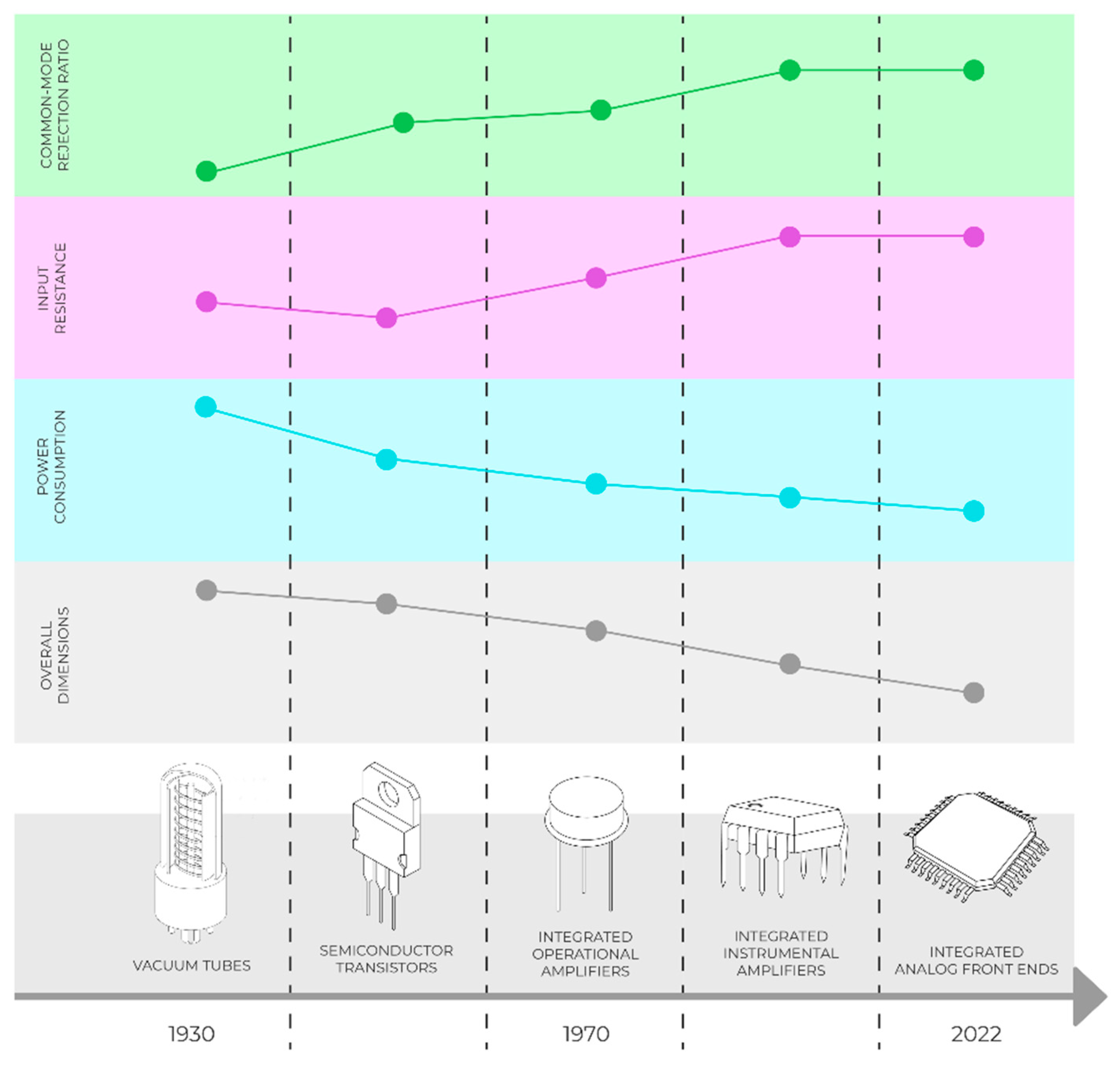
  • Transistors (bipolar and field effects): Ross patented a metal oxide semiconductor (MOS) transistor in 1955.
  • Integrated operational amplifiers: Planar integrated circuit technology appeared in a patent from Fairchild Semiconductor in 1959 (R. Noyce) [11], as well as MOS integrated circuit in 1962 (S. R. Hoffstein), and the first commercial integrated monolithic operational amplifier uA702 based on planar technology was sold in 1964.
  • Integrated instrumental amplifiers;
  • Integral analog and analog-to-digital front-end chip (analog front-end (AFE)).
The purpose of this article is a detailed review of bioamplifier circuits, starting from solutions for vacuum tubes and discrete semiconductor transistors to modern circuits on analog front-ends, taking into account the trends of development of the element base, circuitry, and integration in microelectronics. These trends (over the last century) are shown in the most general form in Figure 2, and are aimed at solving the following technical problems:
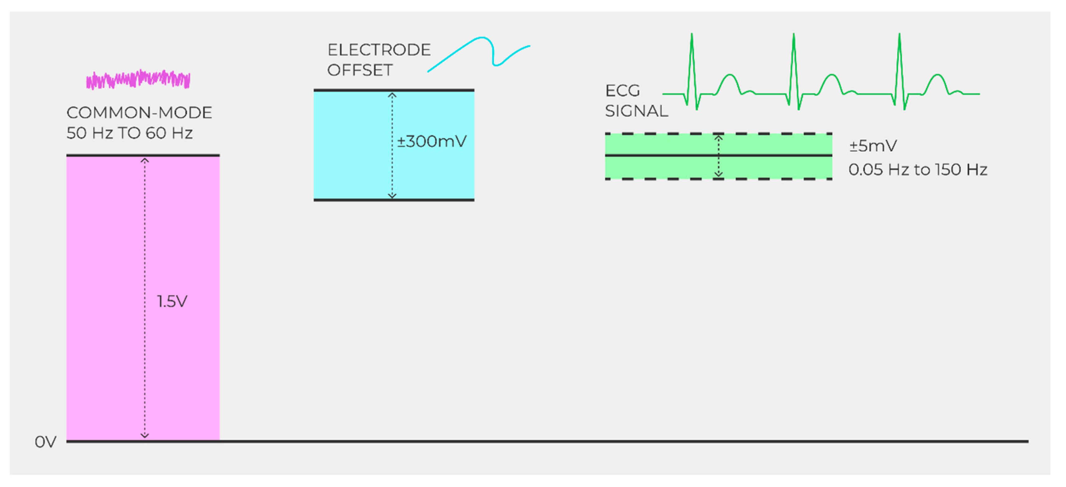
  • Increasing the common mode rejection ratio (CMRR) (50 or 60 Hz of noise, namely high-frequency noise)
  • Increasing the bioamplifier input resistance (due to the rather high resistance of the electrode–skin system);
  • Reduction of power consumption (which is especially important for portable devices);
  • Reducing the mass size of bioamplifiers;
  • Expansion of functional capabilities;
  • Improvement of operational properties.
The approach used in this review not only considers the technical possibilities of using modern front-end circuits, but also traces the circumstances that determine these technical solutions and consequently presents further development in the field of integrated analog solutions for biological signal processing. Because circuits on electronic vacuum tubes and semiconductor transistors are not used in modern medical practice, they are presented as a brief historical reference that is important for understanding the general directions of bioamplifier development. Circuits on individual operational amplifiers, and even more so on integrated instrumental amplifiers, have been widely used until present times (as will be shown in the example of the AD620 chip), so they are presented in more detail. The main emphasis of this review is on the application of modern combined AFE chips for biopotential registration. This section includes a generalized description of the AFE structure and a comparison of the distinctive features of the most widespread models, showing the basic spheres of their application with concrete examples of novel approaches over the last several years.

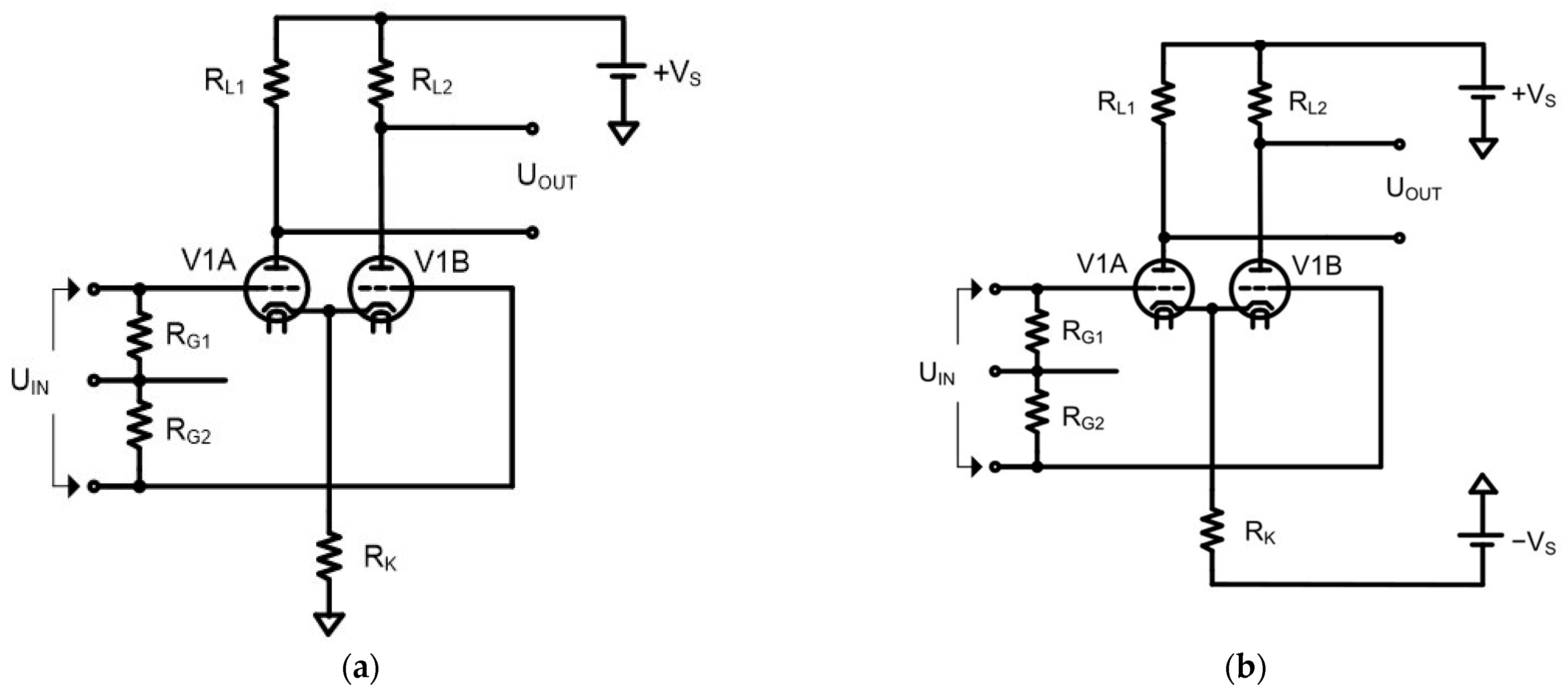
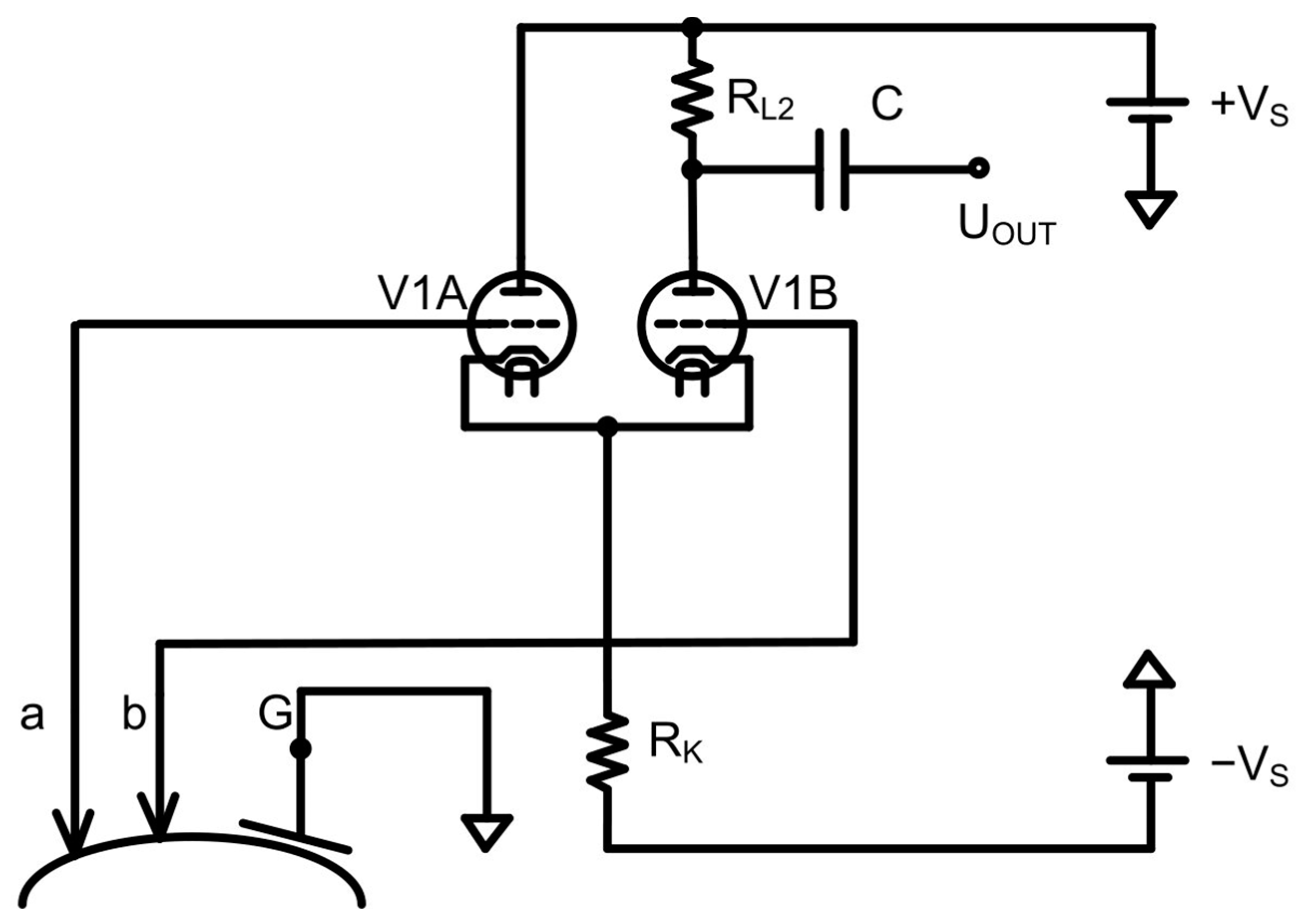
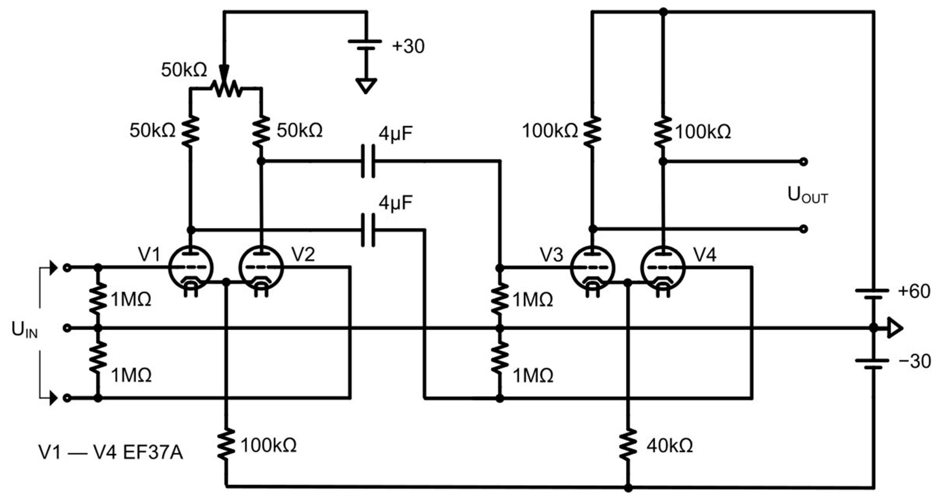
2. Bioamplifiers in Vacuum Tubes

In 1934, W. H. C. Matthews [12], a professional biologist, described the circuit of the first differential amplifier. The amplifier had differential inputs; however, because the common cathodes were tied directly to the common wire of the power supply, it required an offset of the input voltage to half the supply.
In 1936, Alan Blumlein [13] developed Matthews’ ideas by biasing the common cathodes of a differential pair through common resistance to the ground. Alan Blumlein received a patent for his amplifier, but the patent was for broadband signals and not for biological signals. Nevertheless, it was a definite step up from the Matthews amplifier, as it provided better detection of the in-phase signal error owing to the stability of the operating point voltage formed by the current generator based on the power supply (−VS) and the resistor (RK). This important circuit improvement ensures that the signal is bound to half of the total supply voltage, which makes it easier to set the operating point of the differential stage equal to half of the +VS voltage. Schematics of the Matthews and Blumlein amplifiers are shown in Figure 3.
One of the first patented bioamplifiers based on an input differential stage was presented in US patent no. 2147940 by author J. F. Toennies [10], issued on 21 February 1939, with priority in Germany from 1 October 1936 (Figure 4). The difference from the Matthews schemes was the inclusion of an additional negative-polarity power supply (−VS) connected to a common current-retaining resistor (RK) in the cathode circuit. However, the Toennies circuit uses an asymmetrical output of the balance stage (only from the anode of the V1B lamp), which somewhat reduces the common-mode noise suppression.
An example of the differential between the input and output bioamplifiers on electronic vacuum tubes is shown in Figure 5 [14]. This bioamplifier contains two differential amplification cascades, which increase the common-mode rejection ratio of the first stage and total voltage amplification coefficient. The symmetry of the input stage and voltage at the anodes of tubes V1 and V2 is set by a 50-kOhm potentiometer slider, and because of this adjustment, the CMRR increases.
Electronic vacuum tubes have high resistance values in the order of units and tens of MOhms. This fact is used in the toennies circuit (Figure 4). However, when the electrodes are disconnected from the body surface, the operating mode of the amplifier is broken (i.e., is in a saturated state), which is undesirable. For normal operation of the bioamplifier when the electrodes are disconnected, an additional resistance (often 1 MOhm) must be placed at its inputs. This was implemented in the Matthews and Blumlein schemes (Figure 3) and the circuit in Figure 5.
The main features (and disadvantages) of bioamplifiers based on electron vacuum tubes are related to their operational characteristics.
  • They require a high anode supply voltage and high external power supply from the line voltage;
  • Insufficient noise immunity is caused by the fact that the passive electrodes are remote from the amplifier unit.
  • Insufficient suppression of common-mode noise owing to variation in the parameters of the tubes of the input stages;
  • The input impedance of the preamplifier is rather small (about MOhms).
These circumstances require well-shielded lead cables that are fully shielded from external influences with special chambers or rooms for biopotential registration. In addition, a long lead time was required to ensure a stable thermal regime of at least one hour, including a delay in switching on owing to the heating of the lamp cathodes. The limited lifetime of tubes and their low reliability require periodic replacement. The next stage in the development of the element base of bioamplifiers is the use of semiconductor transistors as amplifying elements.

3. Discrete Semiconductor Transistor-Based Bioamplifiers (Bipolar and Field)

There are many circuits of bioamplifiers on transistors, where the input stage in many such devices is still performed in the form of a differential stage [15,16]. In the circuits, electronic vacuum tubes were replaced for transistors, while the circuitry remained essentially the same. Simultaneously, private problems of increasing temperature stability [17], input resistance of bioamplifiers [18], and biosignal display [19] were solved.
Miniature transistor bioamplifiers for telemetry transmission of a biosignal based on series cascades with an input circuit with a common collector are known [20,21], but they do not have such large input resistance values as circuits based on differential cascades [22]. The main features of the operation of the input stages of bioamplifiers on discrete transistors are related to the following features of their functioning.
In comparison with bioamplifiers on electronic vacuum tubes, in circuits on transistors, the supply voltage is 10–15 V, and the power consumption is considerably reduced. This allows the circuit to operate using an autonomous power supply. In addition, pre-preparation for the operation was not required.
Insufficient suppression of the common-mode voltage due to variations in the input-stage transistor parameters determined the insufficient noise immunity. Passive electrodes are remote from the amplifier unit; accordingly, well-shielded withdrawal cables and fully shielded special chambers are required.
The presence of temperature drift owing to the variation in the parameters of the input transistors led to a dependence of the amplifier parameters on changes in the ambient temperature and greatly reduced the stability of the amplifiers. The input resistance of the bipolar transistor-based preamplifiers was a few MOhms, and that of the PN junction and MOS transistor-based preamplifiers was hundreds of megohms. In comparison with the tubes, the amplifiers on the transistors had high reliability.
The next step in the development of bioamplifiers is the use of operational amplifiers (op-amps).

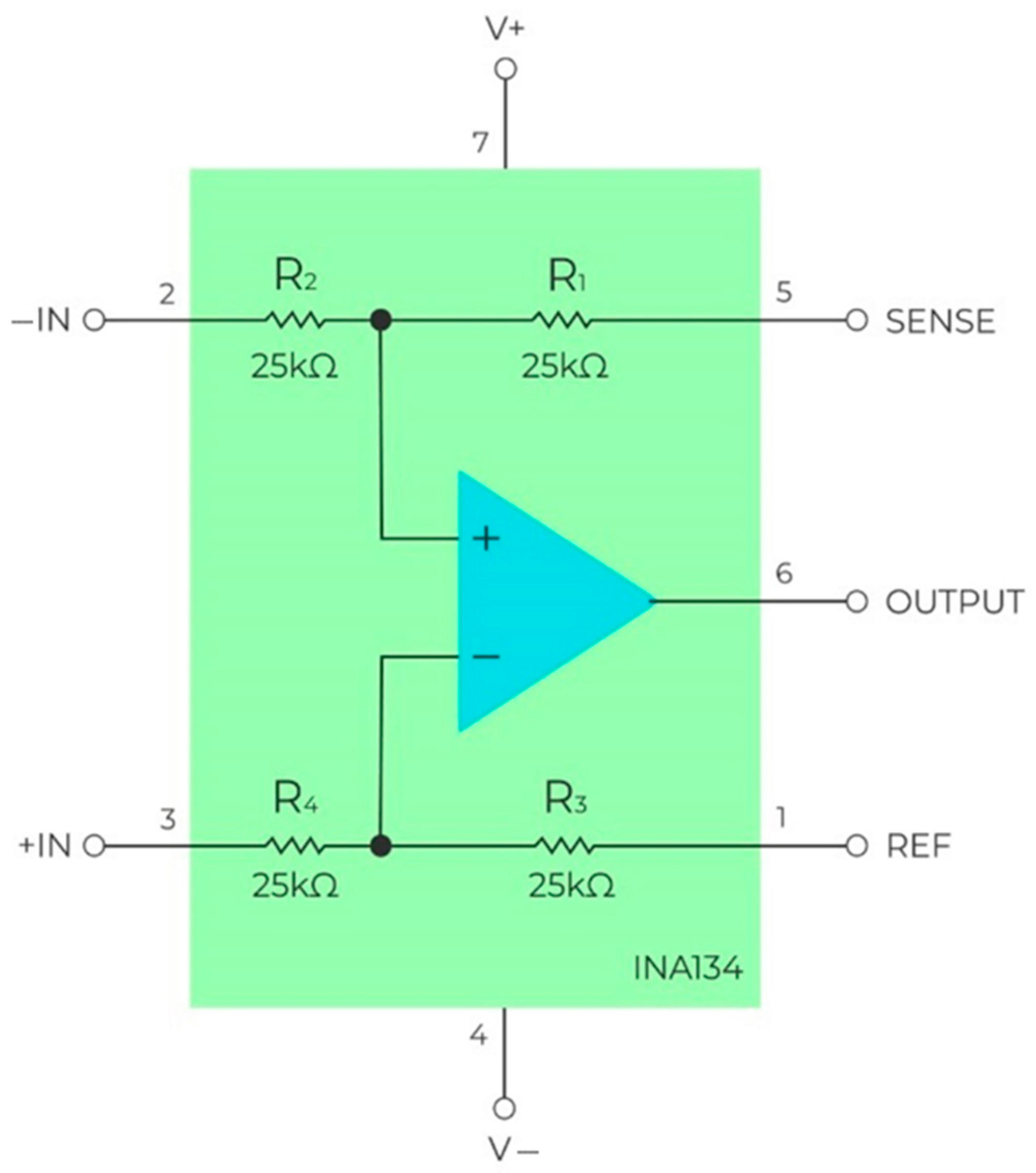
4. Bioamplifiers on Monolithic Integrated Operational Amplifiers

The first devices to use operational amplifiers were circuits, which combined the use of cascades on transistors and Op-Amps. An example of such a device is the N-G circuit of Holmer and Lindstrom (1972), where the input stage is realized on field and bipolar transistors, and the following one is realized on Op-Amps [23].
In 1979, a bioamplifier was established, where the input cascade was built according to the instrumental amplifier circuit on separate Op-Amps [24]. At the same time, there was a problem in providing equality of the resistance values in the shoulders of the differential amplifier for maximum suppression of common-mode noise. Designed to amplify differential voltages, a simple standalone operational amplifier itself has a good CMRR, but everything is spoiled by the circuitry surrounding it (i.e., passive components). Any mismatch in the resistance of the external resistors, including the mismatch of any dividers connected to the reference output, limits the ability of the differential amplifier to suppress in-phase signals, thus decreasing the CMRR. Discrete resistors cannot provide the expected CMRR levels from the differential amplifier.
To solve this problem, the developers of operational amplifiers offered integrated circuits of differential amplifiers with resistors integrated on a single silicon crystal, which allowed the accurate adjustment of their values. An example of such a solution from the manufacturers of the element base is a differential high-performance operational amplifier INA134, with precision resistors on a crystal adjusted by a laser to obtain accurate gain and optimal suppression of common-mode interference (Figure 6) [25].
The gain of the differential amplifier shown in Figure 6 can be calculated using Equation (1) (assuming that resistors R1 = R3 and R2 = R4) [26]:
V o u t = R 1 R 2 ( V I N + V I N ) + V R E F
Using Equation (2), we can estimate the effect of resistor tolerance (TR) on the CMRR of a differential amplifier with a single gain coefficient G = 1 V/V:
C M R R D I F F 20 log ( 1 + R 1 R 2 K )
In this formula, K is the scatter of the resistance ratios of resistors R1 and R2 as well as R3 and R4, which in the worst case can be 4·TR:
  • If TR = 1%, the worst-case CMRR value is 34 dB.
  • If TR = 0.1%, the worst-case CMRR value is 54 dB.
The circuit shown in Figure 6 also has other disadvantages. Normally, the input impedance of an operational amplifier is very high, ranging from MOhms to GOhms. However, connecting the feedback and reference voltage circuits (which are usually simple voltage dividers) will decrease and unbalance the impedance, resulting in an increased load on the input sensor and decreased accuracy. If we need to amplify a weak sensor signal (such as in the case of biological potentials), the low gain accuracy in the presence of large-amplitude noise would make it unsuitable for measurement purposes.
The application of the instrumental amplifier circuit allowed the use of a number of solutions to reduce the influence of common mode noise, particularly the so called “Right Leg Driver (RLD)” [27], although the problems of measuring a small differential signal in the presence of a large common mode voltage concerned the developers and many for years afterward [28].
However, the main features of the input stages of bioamplifiers in integrated operational amplifiers are related to the properties of the operational amplifiers themselves.
  • High common mode rejection ratio;
  • High thermal stability of input cascades;
  • Small nonlinear distortions of the input signal;
  • A wide range of supply voltage variation;
  • Low power consumption from the power supply.
The latter circumstance made it possible to provide autonomous work of the bioamplifier from the built-in power supply (accumulator) [29]. Further logical development was made on the basis of integrated instrumental amplifiers [30].

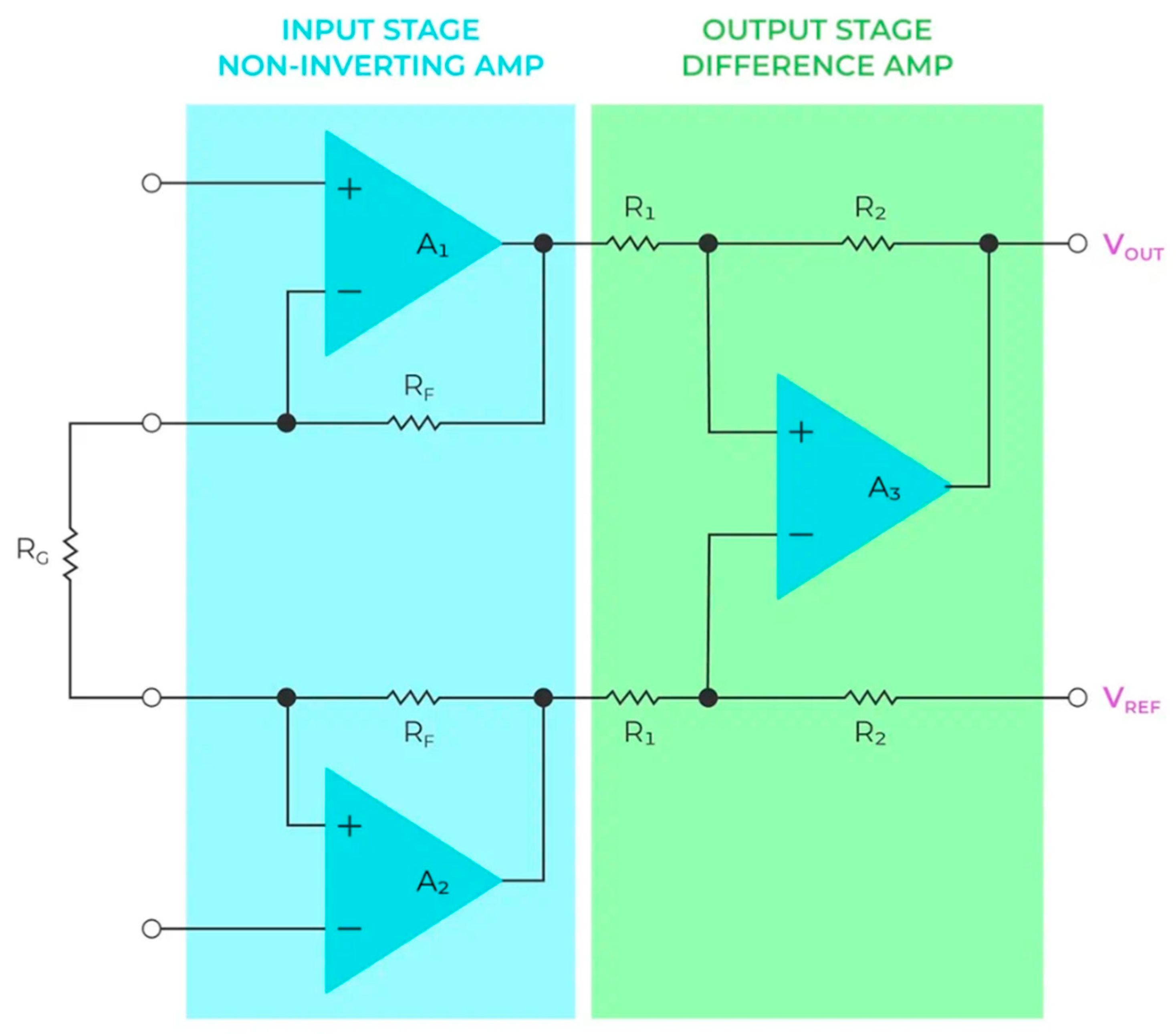
5. Bioamplifiers on Monolithic Instrumentation Amplifiers

Monolithic instrumentation amplifier integral circuits (ICs) were developed to meet the demand for instrumentation amplifiers that would be easier to use than separate operational amplifier circuits. The first representatives of monolithic chips became common in the early 1970s [31]. These circuits incorporate variations of 2-Op-Amp or 3-Op-Amp circuits (the most common schematic is shown in Figure 7) while providing laser-tuned resistors and other advantages of the monolithic IC technology [32].
Because the active (transistors) and passive (resistors and capacitors) components are combined on the same silicon substrate, they can be carefully matched, allowing for a high CMRR from the device (the main feature of bioamplifiers). The input-stage amplifiers also provide high impedance, which minimizes the load on the input electrodes [33]. A single gain control resistor (RG) allows the designer to select any gain within the operating voltage range of the device. The output stage is a traditional difference amplifier, as shown in Figure 6; therefore, for all calculations of the output gain and CMRR, the aforementioned formulas of Equations (1) and (2) can be used. The ratio of the internal resistors R2 and R1 sets the gain of the internal difference amplifier, which is usually G = 1 V/V for most instrumentation amplifiers (as the overall gain is determined by the amplifier in the first stage). Such a design is simple to implement, with a small footprint and fewer components, resulting in a lower system cost. The design is also compatible with single-source power using a voltage reference (VREF) output.
IC technologies, such as laser wafer trimming, allow monolithic integrated circuits to be tuned with very high accuracy and provide low cost for high-volume production. An additional advantage of monolithic instrumentation amplifiers is their availability in miniature mini small outlines (MSOP) or leadframe chip scale (LFCSP) packages, which are designed for use in high-volume production [34]. This significantly reduces the size of different medical devices for biopotential registration, such as electrocardiographs and Holter monitors.
Analog Devices introduced their first high-performance monolithic instrumentation amplifier, the now not-so-famous AD520, in 1971 [35,36]. In the past, such amplifiers were too expensive, so up to the end of the 1980s, bioamplifier circuits were preferentially assembled on separate transistors [37] or operational amplifiers [38,39], although there were novel designs for monolithic instrumentation amplifiers (it was rather difficult to find any articles about real implementation of the AD520) [40].
In 1992, AD620 was introduced and became the industry standard for high-performance, low-cost instrumentation amplifiers, which have been widely used since the 1990s to design biopotential amplifiers [41]. AD620 is a second-generation version of the classic AD52X series amplifier that embodies a modification of the circuit on three operational amplifiers. Laser trimming of the thin-film resistors directly on the chip allowed the gain to be accurately set to 100, within a 0.3% maximum error, using only one external resistor. AD620 has been an industry standard for a long time and has been used in many developments since the middle 1990s. Here, we can find systems for recording EEG signals [42,43], including long-term monitoring [44], electrocardiogram signals [45], and muscle activity [46,47]. Although more advanced integrated instrumentation amplifiers appeared later, AD620 is still popular in the development of “homebrew” bioamplifiers for original scientific research worldwide, as well as for teaching purposes (especially for graduate qualification works), owing to its reliability and low price [48,49]. Rather detailed review of current AD620 applications is presented in [50,51].
The main reason for the popularity of homebrew bioamplifiers based on integrated instrumentation amplifiers, such as the AD620, was the simplified circuitry of the whole device (in comparison with solutions on discrete operational amplifiers and, moreover, transistors), and detailed application notes from chip manufacturers were no longer required from the user deep knowledge in analog circuitry. It was also facilitated by the market’s appearance in the late 1990s and the early 2000s of affordable and inexpensive 8-bit microcontrollers (such as the AVR family by ATMEL and PIC from Microchip), which had built-in analog-to-digital converters, allowing them to be designed and built in the presence of minimal equipment prototypes of working devices for recording biopotentials. Interface chips, such as MAX232, which appeared nearly at the same time, allowed connecting the device to a personal computer via a standard COM port to transmit data in digital form for further processing by software tools. Similar developments are still found today, as shown in [50,51], with individual microcontrollers replaced by debugging boards such as Arduino and a more advanced USB interface in the case of wired data transfer.
One of the most successful (and therefore widespread) configurations of a biopotential recorder based on AD620 is still the circuit proposed by specialists of Analog Devices in 2003 [52]. Its circuitry was simplified using a microconverter of the ADuC family, which combines an analog-to-digital converter (ADC), filters, and a microprocessor in one integrated circuit (Figure 8).
The analog part uses a typical approach, with an instrumentation amplifier as the input and an operational amplifier with current feedback on the right leg (RLD). One of the features of the proposed solution is the bipolar power supply, which currently does not appear comfortable for designers. Based on this concept, many devices for electrocardiogram recording have been developed, including wearable devices [53].
In the early 2000s, more advanced instrumentation amplifiers appeared, gradually replacing AD620 and its analogs. Thus, in 2003, AD8221 was introduced [54]. This instrumentational amplifier in the MSOP package provided an increased CMRR with a higher bandwidth and improved DC characteristics compared with the standard industrial AD620 series amplifiers [55,56,57].
The AD8422 instrumentation amplifier was a third-generation development of the industry standard AD620, and was released in the late noughties. AD8422 uses new processes and design techniques to achieve a higher dynamic range and lower errors than previous devices while consuming less than a third of the power of the original AD620 design [58,59]. Simultaneously, Texas Instruments released a new INA333 instrument amplifier. The INA series of instrument amplifiers was originally designed and manufactured by Burr-Brown but was later bought outright by Texas Instruments. The INA333 became a good choice for building biopotential amplifiers [60,61], including wearable device application [62], mainly due to the unusual combination of such characteristics as a low spectral noise level at the input (0.05 μV/√Hz in the band of 10…1000 Hz) and the ultra-low own current consumption (up to 80 μA maximum over the entire operating temperature range) [63]. The achievement of such parameters as a low input leakage current (200 pA) and virtually no input voltage drift (0.1 μV/°C) made it possible to use the INA333 for recording even smaller-amplitude EEG signals starting from 2011 [64] and up to the present days [65,66,67,68].
In fact, despite significant improvements in various parameters of instrumentation amplifiers and different monolithic technologies, none of these improvements have caused any fundamental changes in the scheme of biopotential amplifiers. Simultaneous with the development of instrumentation amplifiers, a new type of analog-to-digital converter—the so-called sigma-delta ADC—having a high (up to 24 bits) resolution, was in active development [69,70], and therefore projects suggesting that the minimization of the number of analog signal preprocessing blocks, passing directly to work with digital signals as quickly as possible, began to appear. In 1996, the authors of [71] abandoned even instrumentation amplifiers replaced them with simple buffers on the operational amplifiers. Although the idea seemed potentially successful [72], its practical implementation was hindered by insufficient characteristics of the first sigma-delta ADCs. Such a concept returned to the market only in the late 2000s in the form of integrated single-chip solutions or analog front-ends for biopotential registration, opening a new shining era for small and smart devices.

6. Bioamplifiers on Integrated Analog Front-Ends

6.1. Basic Information about Integrated Analog Front-Ends

The requirements of an even higher degree of integration, a reduction in the space that chips occupy on the printed circuit board, low parasitic characteristics, and low power consumption are fundamental to modern developments, regardless of the final application. Analog front-ends were originally developed to solve these problems as combined solutions on a single silicon chip [73], including the following blocks:
-
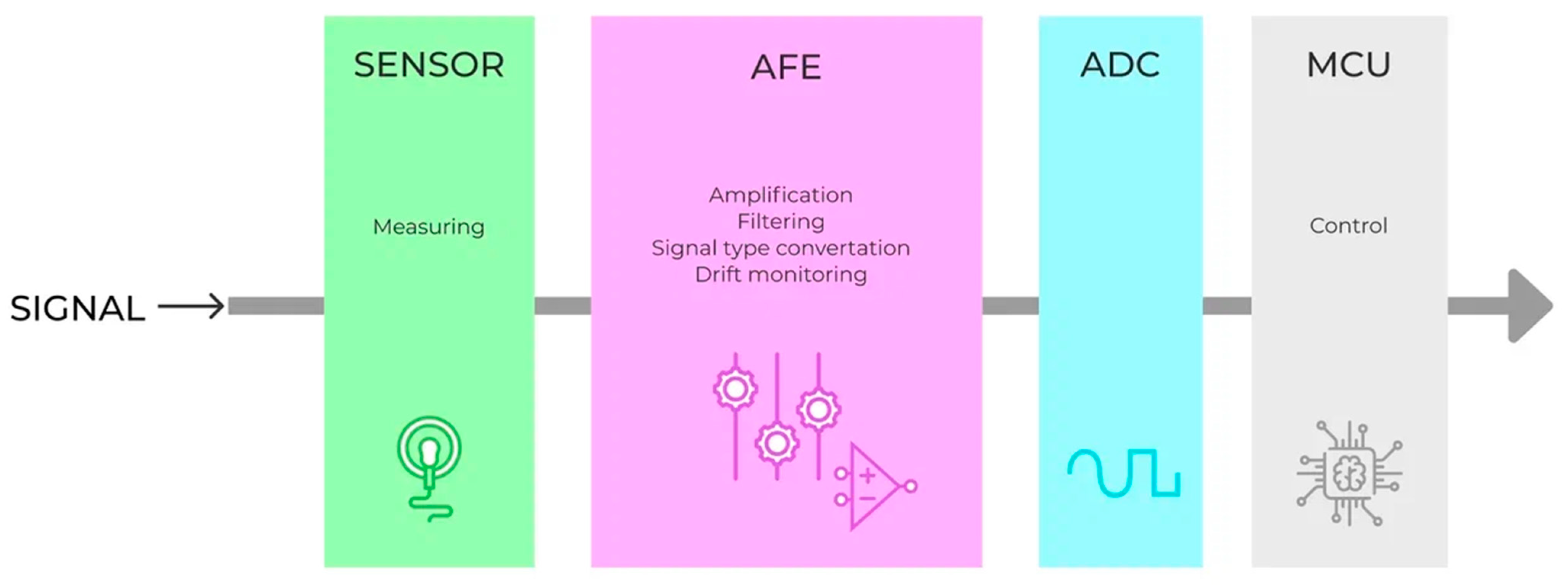
Analog units (operational amplifiers, comparators, filters, etc.) are required to convert and preprocess the input analog signal.
-
Analog-to-digital and digital-to-analog converters;
-
A digital interface to transmit data and control the entire system;
-
Power subsystem (linear voltage converter, reference voltage source, battery charging circuit, and power supply supervisor).
All these blocks are composed in a certain way, depending on the application area of the final device, and serve to ensure high performance of the input signal processing with minimum power consumption. However, unlike programmable logic chips, these blocks are hardwired in the AFE design and cannot be changed in the future, making the final device less flexible.
Most AFEs connect directly to the microcontroller via the serial peripheral interface (SPI) or interintegrated circuit (I2C) serial interfaces for data transfer and peripheral configuration, with minimal external components (mostly passive) required. AFEs can be precise or high-speed, such as high-frequency signals in transceiver circuits [74] or radio-frequency identification (RFID) tag handling [75]. There are also specific AFEs for medical applications (registration of biopotentials [76], pulse wave signals, processing of ultrasonic signals [77], etc.), power monitoring, metering, and many others.
Most acquisition systems consist of three main parts: an analog sensor that converts physical signals into an electrical form (current or voltage), an analog signal preprocessing unit, and a microcontroller (MCU) with an external or built-in ADC to digitize the analog signal and its further processing in digital form, storage, and transmission (Figure 9).
The AFE itself performs several functions, depending on the application. The first of the AFE functions amplifies signals whose amplitudes are too small to be directly digitized. The AFE circuitry uses amplifiers to produce an output voltage hundreds or thousands of times greater than the voltage produced by the sensor. Operational, differential, or instrumentation amplifiers are typically used for this purpose, which can vary greatly in cost and power depending on the performance required. The AFE amplifier structure varied depending on the characteristics of the sensor. For example, if the sensor output is differential and has low impedance, a simple differential input can be used. However, if the sensor output is differential and has high impedance, a more complex programmable instrumentation amplifier with appropriate high-impedance inputs may be required.
Another function of the AFE is to filter unwanted noise and isolate useful frequency ranges, such as to satisfy the Nyquist frequency criteria or remove DC bias. All this noise must be removed from the analog signal before it can be converted into a digital form. As a standard, AFE chips contain blocks of analog low-pass (including anti-aliasing) and high-pass filters and, much less frequently, rejection filters (assuming that filtering from a line of 50–60 Hz of noise will be performed in digital form).
The third function of AFEs is to convert signals from one type to another. For example, the most common analog signal transducers produce voltage as an output (e.g., standard instrumentation bioamplifiers, pressure sensors, analog accelerometers, etc.), but some produce current as an output. Because standard analog-to-digital converters embedded in AFEs (sigma-delta or successive approximation ADCs) do not accept current inputs, one must first convert the current to voltage before feeding it to the ADC input. This current-to-voltage conversion is performed by an additional AFE unit called a transimpedance converter (current-to-voltage), which also amplifies the resulting voltage to the desired level. Such transducers are mandatory elements for AFEs designed to record photoplethysmographic signals (for pulse oximeter development).

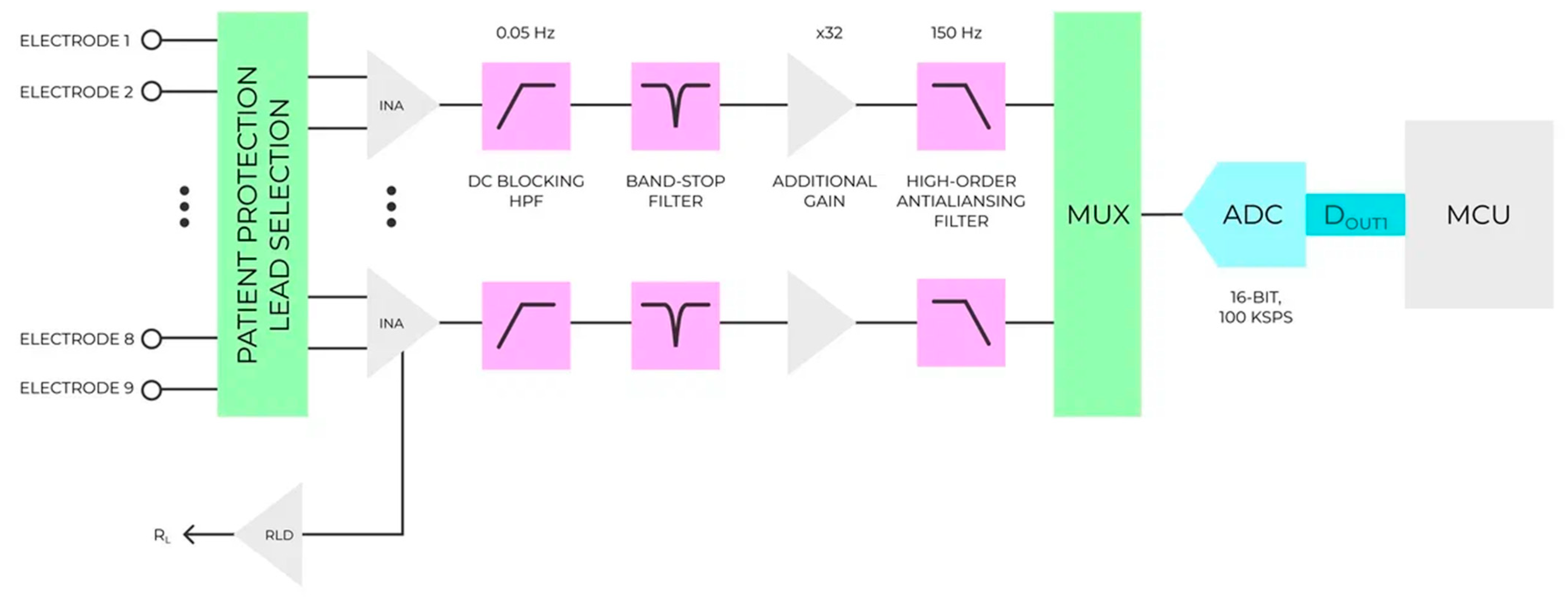
6.2. Analog Front-End Solutions for Biopotencia: Registration

AFEs for biopotential registration have become a logical development of standard circuits on instrumentation amplifiers, combining on one crystal several standardized registration channels with programmable instrumentation amplifiers (or a programmable gain array (PGA)), a high-resolution ADC [78], and a number of specific blocks (RLD, test signal generator, lead connection tester, and many others). The placement of all typical blocks of a bioamplifier on a single crystal reduces the size of the entire device, improves the quality of the recorded signals, and reduces the power consumption of the entire system, providing flexible adjustment of the recording parameters in real time, which is especially important for the development of continuous monitoring devices, such as Holter monitors.
The basics of this concept are well described in the Texas Instruments technical report [79]. For comparison, the schematic of a typical bioamplifier based on an instrumentation amplifier is shown in Figure 10. The standard ADC reference voltage is approximately 2.5 V, which means a gain of 500 (assuming that the ECG input signal amplitude is no greater than 5 mV). The total gain is shared between the instrument amplifier (INA) and an additional gain block (one or more operational amplifiers). The gain must be added to the INA such that the DC offset does not place the INA into the saturation mode. The DC component was removed before further amplification. Therefore, a high-pass filter (HPF) with a stop frequency of 0.05 Hz is added. After removing the constant component, the line disturbance (50 or 60 Hz), the amplitude of which may be too high (up to several hundred mV) against the background of the small amplitude of the signal itself, was removed from the signal. It should be noted that the amplifiers used for these gain-filtering stages should be low noise so that they do not dominate the system noise. For portable devices, these amplifiers should also have low power consumption. This combination increases the cost of precision amplifiers required for the system. The gain stage was followed by a smoothing filter. Typically, a fourth-order or higher active low-pass filter is used. Finally, the multiplexer unit (MUX) feeds the signals to the ADC with only quasi-synchronous digitization of all channels achieved, which requires the ADC to have a higher operating frequency (at least 100 kHz for eight channels); therefore, such circuits usually use successive approximation ADCs. Obviously, all signal processing, including filtration and amplification, is analog. This significantly limits the flexibility of the entire system [80].
Because digital signal processing is relatively cheaper and provides more flexibility, with the advent of inexpensive and reliable sigma-delta ADCs with high resolution (up to 24 bits), developers have begun to move away from analog signal processing to the digital domain as soon as possible, reducing the number of analog blocks to a minimum [78].
Figure 11 shows an analog front-end in combination with a sigma-delta ADC. Originally, the speed of the delta-sigma ADC was limited to a sampling rate of a few kHz, but advances in technology allowed it to be increased to hundreds of kHz while maintaining excellent DC and AC performance.
When comparing Figure 10 and Figure 11, it can be seen that there is a significant reduction in hardware blocks, resulting in both a lower cost and lower power consumption. Most of the blocks (including the high-pass and low-pass filters, 50-Hz rejection filter, and gain cascade) were eliminated from the circuit. In addition to the advantage of higher resolution, the sigma-delta ADC has much lower requirements for low-pass filters. Complex active anti-aliasing filters, which require several amplifiers for implementation, can be replaced by a simple single-pole RC filter. The DC blocking filter is also eliminated because the inherent noise of the ADC is much lower than that of the previous solution and the total value of the gain can be much lower. Thus, no DC information was lost. Digital filter implementation also allows the use of adaptive DC removal filters for an overall faster response and better rejection characteristics.
A generalized structural diagram of the AFE for recording biopotentials is shown in Figure 12. The signal from the electrodes connected to the patient goes directly to the input of the chip (multiplexer unit), without additional amplification or analog filtering of the input signal. The schematic does not include input circuit protection against overvoltage or static electricity, nor does it include patient leakage current protection blocks, which are usually not part of the AFE structure and are added as external elements. The connection configuration was set using a switching unit, which is a digitally controlled analog multiplexer (MUX). In addition to the signal from the electrodes, additional signals can be input: a test signal from the built-in generator (GEN), a signal from the built-in analog temperature sensor (TEMP), circuit supply voltage, or other combinations of signals.
This block is extremely important for presetting the device, as it allows one to perform an express diagnosis of the operation of all the internal circuit components. The analog signal is pre-amplified by a PGA, which provides a high input impedance to the circuit and suppresses the common-mode interference. The analog signal then passes through an electromagnetic interference filtering unit (EMI filter) with a cut-off frequency of approximately 3 MHz. In contrast to standard circuits for recording biopotentials, additional analog filtering of the input signal is most often not applied. High-pass filters to remove the drift of the constant component and 50- or 60-Hz filters to remove line interference in the general structure of an AFE are absent. After the anti-aliasing filter, the signal goes to a high-resolution analog-to-digital converter (ADC), with the most common option being a 16- or 24-bit sigma-delta ADC. The signal is digitally stored in the corresponding registers and is ready for further transfer via a serial SPI or I2C interface built into the control unit (CU). In addition, the standard scheme contains a built-in tact clock generator (CLK), which sets the operation of the entire system, the maximum sampling rate, the data transfer rate. Power supply, including a linear voltage converter, which sets the power for the digital and analog blocks of the device with a reduced supply voltage (up to 1.8 V), which is extremely important for building systems running on batteries, and a reference voltage source (with the possibility of using a bipolar supply to expand the dynamic range). Specialized units for recording biopotentials include the right leg drive, electrode connection reliability checks, and some more specific nodes (e.g., an R-wave extractor from the electrocardiogram signal).
The most important advantage of such integrated solutions is their ability to flexibly customize operating modes for maximum energy efficiency. Among the configurable parameters, the most important are as follows:
The ability to disable signal registration channels (each of which is a separate device with input cascades, ADCs, and registers for storing the conversion results) is important. Disconnected channels consume a minimum amount of power (roughly units of microamperes) and can be activated at any time.
  • Changing the sampling rate for each of the signal registration channels;
  • Changing the amplification factor of the input signal;
  • Changing the cutoff frequency of built-in high-frequency filters
  • Changing the analog-to-digital conversion bit rate.
Despite the obvious advantages, these schemes do not solve the disadvantages, the main one being the absence of preliminary analog filtering of the input signal. Because they do not use high-pass filters, the constant component of the signal arrives at the ADC without any changes and can significantly complicate further signal processing, whereas the drift of the constant component of the signal, especially during motor activity, can vary over a wide range of amplitudes. Similarly, 50- or 60-Hz line interference arrives at the input, which, along with the baseline drift, limits the maximum gain of the input instrumentation amplifier (a maximum gain value of 10–12 times) and reduces the signal-to-noise ratio.

6.3. AFEs on the Market

For bioamplifiers, a breakthrough in this area was the appearance of the first combined analog–digital AFE chips from Texas Instruments. In 2010, this company introduced the first device in a family of fully integrated analog front-ends for portable and high-end electrocardiogram and electroencephalogram equipment. Texas Instruments currently offers a family of AFEs (ADS129x) for recording biopotentials with varying numbers of channels (from one on ADS1291 to eight on ADS1298). All chips have a similar structure, which does not differ from that shown in Ref. [81]. Market analysis shows that today, all major semiconductor chip manufacturers have their own interface chips for recording biological potentials, which have a similar basic structure and differ (depending on the manufacturer) in individual functional blocks.
The AFE MAX30003 chip from Maxim Integrated has the lowest declared power consumption and provides many functions for additional power saving as well as some specialized blocks that are missing in other devices [82]. The first and foremost is the built-in ECG R-wave detection hardware block for R-R interval detection using the adapted Pan-Tompkins QRS extraction algorithm. The temporal resolution of the R-R interval was approximately 8 ms, which allowed heart rate measurement without additional computational resources on the microcontroller side. In addition, unlike Texas Instruments’ solutions, Maxim’s AFEs include various programmable low-pass and high-pass filter options and a decimation filter consisting of a cascade integrator, followed by a programmable finite impulse response (FIR) filter to implement high-pass and low-pass choices. High-pass filter options include a first-order Butterworth infinite impulse response (IIR) filter with an angular frequency of 0.4 Hz, as well as end-to-end tuning for DC coupling.
Analog Devices uses a 14-bit ADC with a sampling rate of 2.048 MHz in its ADAS1000 AFE circuitry, unlike other manufacturers [83]. After processing an oversampled ×1024 signal, the effective resolution was comparable to that of other competitors.
Of particular interest is a purely analog solution from Analog Devices: the AD8232 chip [84]. As the input stage, this microcircuit uses an instrumentation amplifier with two coordinated current amplifiers controlled by the voltage, namely, transconductance operational amplifiers, in contrast to circuits using standard operational amplifiers, which allows a significant increase in the in-phase suppression factor [85]. A simplified circuit is shown in Figure 13.
The input stage also includes a high-pass filter (whose cutoff frequency is set by external passive components), which allows filtering frequencies close to the signal constant component, providing an initial gain of 40 dB with a drift of the signal constant component of up to ±300 mV. For this purpose, an additional operational amplifier was used, which acts as a filter of high frequencies of the first order (with a steepness of response of 20 dB per decade), allowing one to eliminate the drift of a constant component at poor contact with the electrodes. For the power supply of the input circuit stage, a power step-up converter is used, which increases the limit level of the input in-phase signal without transitioning the amplifiers into saturation mode at a high level of in-phase noise at the input. In addition, the circuit includes an active ground-forming block (Right Leg Drive loop) designed to form an inverted version of common-mode interference on the third electrode for the purpose of additional suppression of common-mode interference.
A separate general-purpose operational amplifier allows the addition of a second-order low-pass filter to the overall circuit and increases the gain to the desired value. The combination of low-pass and high-pass filters makes it possible to create a bandpass filter with a sufficiently narrow amplitude–frequency response suitable for extraction from the entire ECG signal frequency range of only the part that belongs to the QRS complex, which is suitable for the extraction of R-waves. Simultaneously, by using the input circuit on transconductive amplifiers and active earth, we eliminate the influence of line noise, which minimizes the need for additional digital filtering of the output signal.
The most important electrical characteristics of the selected for comparison are listed in Table 1. The sources of information were the manufacturers’ official technical documentation from publicly available sources and the references to which they were given earlier. The best values for these categories are shown in bold font.

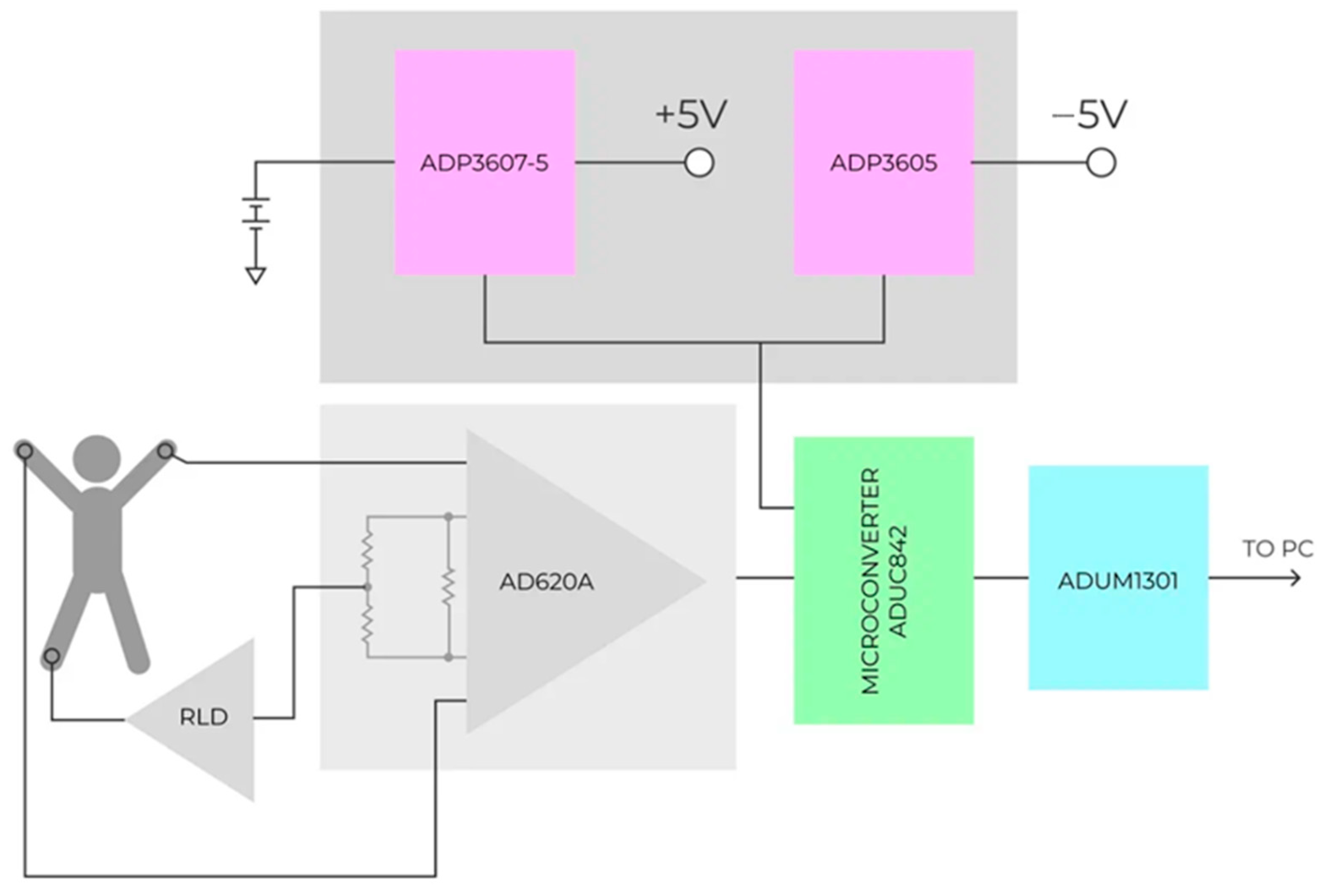
7. Implementation of AFEs in Real Applications

7.1. Articles Overview and Statistics

In the last part of our investigation, we reviewed 100 articles to analyze the use of AFE for medical signal processing. During familiarization with the materials, six groups of articles were identified according to the electrical signals, namely the AFEs used in the processing of ECG, EEG, EMG, electrooculography (EOG), and electrogastrography (EGG), and the last group of articles included information about the use of AFEs for non-trivial tasks.
When reviewing the articles, the quantitative superiority of the material associated with the registration and processing of the ECG signals was clearly revealed. The presence of such a large number of articles related to electrocardiograms can be explained by the increased interest in the development of wearable electronics that allow monitoring the activity of a patient’s heart and, as a consequence, the state of cardiovascular health without performing a long examination. The next most frequently analyzed signal was the electroencephalogram. There are significantly fewer articles devoted to the development of AFE-based devices that allow EEG recording than ECG recording. Nevertheless, the problem of recording and processing the signals received from a portable device is relevant.
Figure 14 shows the distribution of articles by the medical signals processed in them. Simultaneously, the superiority of articles in which a cardiac signal was used as a biological signal was confirmed.
In addition to analyzing the quantitative distribution of articles by the signals used, the distribution of articles by publication year was considered. As shown in Figure 15, interest in using AFEs for various applications has not diminished over the past five years.

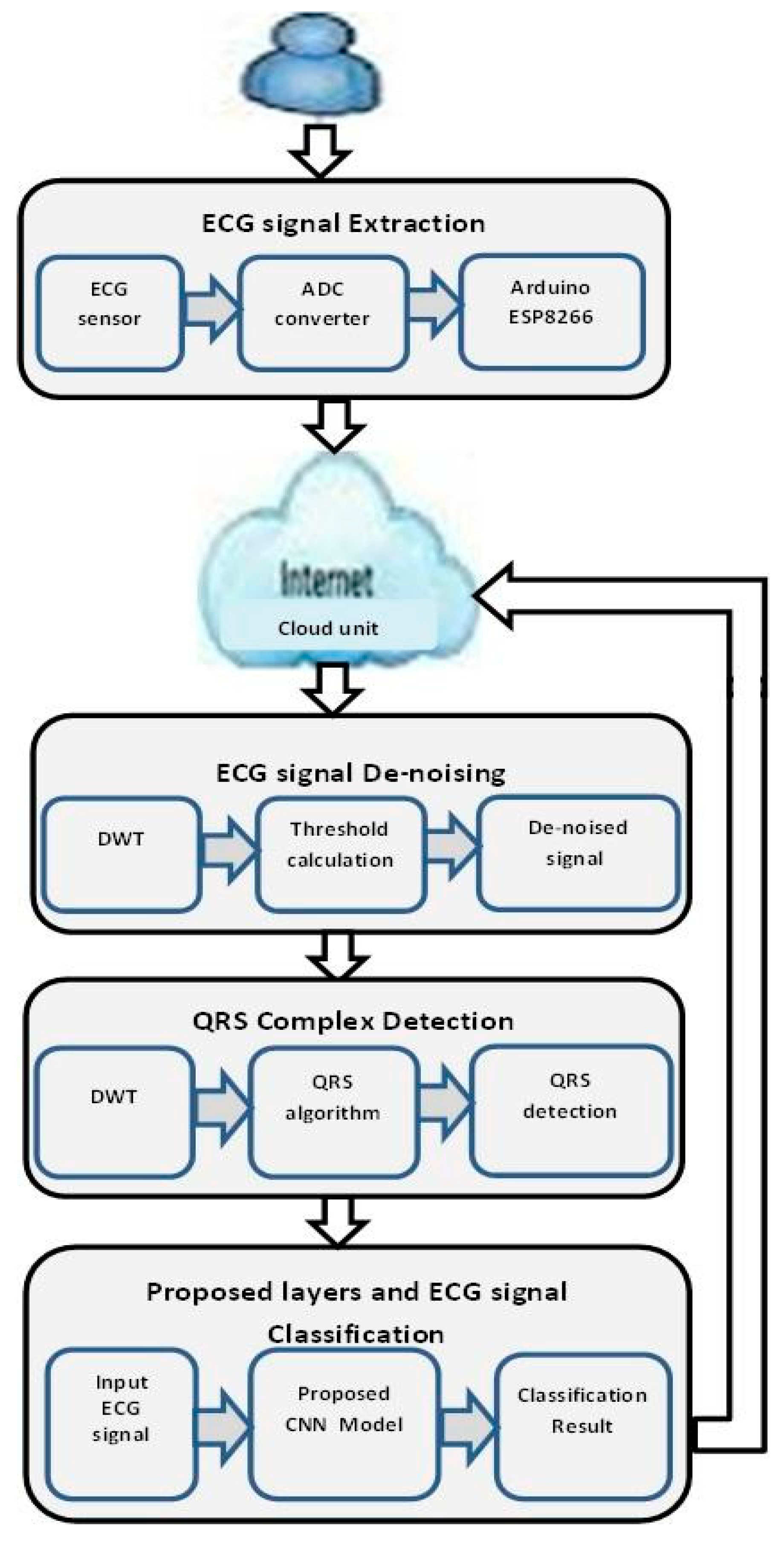
7.2. Application of AFEs for ECG Registration

As expected, the number of articles and interest in the problem of using AFEs in the processing of medical signals has increased proportionally. Therefore, in the early 2010s, with the invention of AFEs for medical purposes, special attention was paid to the development of portable devices that allow the recording of ECG signals. The absolute champion here is AD8232 from Analog Devices, which is primarily used to develop low-cost portable devices for ECG signal registration [86,87,88,89]. The development of portable systems containing AFEs is usually determined by the presence of a large number of countries with insufficient fast and good medical care. For example, fast and qualified medical care cannot always be provided in remote localities. Therefore, the presence of a portable system that registers a cardiac signal makes it possible to increase the effectiveness of treatment and diagnosis [90,91,92].
A good example of a modern method of ECG acquisition was presented in [88]. The aim of this study was to create a low-cost portable device that allows the registration of an ECG signal. The main board used for the development of the project was the Texas Instruments TM4C123G LaunchPad evaluation kit. It is a low-cost evaluation platform for ARM Cortex-M4F based microcontrollers with an 80-MHz oscillator and a 32-bit processor. The AD8232 heart rate monitor board was used as an ECG sensor to acquire the ECG signal. This board can extract, amplify, and filter small biopotential signals in noisy environments. The device was attached to the chest with three disposable electrodes and connected to a LaunchPad analog pin. The results indicated that the AD8232 board, Texas Instruments TM4C123G LaunchPad, and Nextion touch screen are compatible boards that can be used for long-term ECG monitoring.
Many developers are trying to implement an inexpensive device for long-term electrocardiogram signal registration based on AD8232 in conjunction with Arduino platforms [93,94,95,96,97] or the more powerful and expensive solutions such as Raspberry Pi [98] or LaunchPad from Texas Instruments. In recent years, there have been many articles devoted to the open-source development of mobile devices for ECG registration [99,100,101]. The prototype of such solution on ArduinoNano is shown in Figure 16 [100]. The AD8232 chip is also found in projects devoted to the indirect estimation of blood pressure by pulse wave propagation time, where it acts as a reference channel for ECG signal registration [102,103].
To confirm this approach, consider the latest work of Hamad and Jasim [97], in which the following ECG registration system was proposed: This work can serve as a good illustration of modern AFE chip implementation for recording ECG signals. They proposed the ECG monitoring and classification system shown in Figure 17. First, the ECG signal was extracted based on AD8232 with the Arduino platform, and then denoising processing was used to remove the noise from the signal and detect the peak of the signal. Finally, a convolutional neural network (CNN) model was designed for ECG classification. The sensed data are further transmitted to the web server, where anyone can remotely monitor the status of a patient.
After 2015, interest in systems providing continuous heart rate estimation significantly increased [104,105,106] because the AD8232 chip in one of the standard connections is ideal only for reliable registration of an R-wave in one lead. Many of the proposed solutions use a smartphone or tablet as a data processing module [107,108], whereas others are complete microcontroller-based devices [109,110].
Another common device concept using AD8232 is related to the Internet of Things (IoT). IoT allows entities to be observed or supervised remotely from one existing network infrastructure to another, generating moments for more direct unification of the visible world into computer build systems, resulting in improved effectiveness, perfection, and economic benefit in inclusion to reduce human intervention, enabling an entity to accumulate and interchange the data. Most studies in this field using AD8232 are dedicated to IoT-based health monitoring systems [111,112] based on the Arduino platform [113], more complicated solutions [114], real-time heart rate variability monitoring [115], and diagnosis of cardiovascular disease [116,117,118].
Some studies have focused more on digital signal processing obtained with AD8232 and on the detection of various arrhythmias [119,120,121,122], methods of detecting atrial fibrillation [123], sudden cardiac death prediction [124], or devotion to solving more original tasks such as biometry [125,126,127]. The possibility of using the AFE AD8232 in clinical practice has not been ignored, as some authors have tried to make comparative studies between a single-lead AD8232 heart rate monitor and a standard electrocardiograph [128,129,130,131].
Similar to AD8232, the ADS1298 AFE from Texas Instruments is widely used for the realization of both portable [132,133,134] and full-fledged electrocardiographic systems [135,136,137,138]. Other studies have focused on more complex algorithms for processing electrocardiogram signals, as the ADS1298 allows obtaining a signal quality that is no worse than that of standard cardiographs. These are primarily algorithms for removing baseline wander and electromyography interference [139], 50- or 60-Hz interference cancellation algorithms for ECGs [140], and R-wave detection in real-time [141]. The development of portable AFE-based cardiographs on chips from Texas Instruments with fewer channels, such as ADS1292R (two-channel system) and ADS1294R (four-channel system), was particularly unsuccessful [142,143].
The ADAS1000 microcircuit from analog devices has not shown special popularity, which is most likely owing to the excessive complexity of its structure and high cost (in comparison with the microcircuits of the ADSx series and single-channel AD8232). Its main advantage is the possibility of implementing a respiration registration channel owing to the built-in impedance channel [144,145,146], although attempts have been made to create portable cardiographs based on this AFE [147].

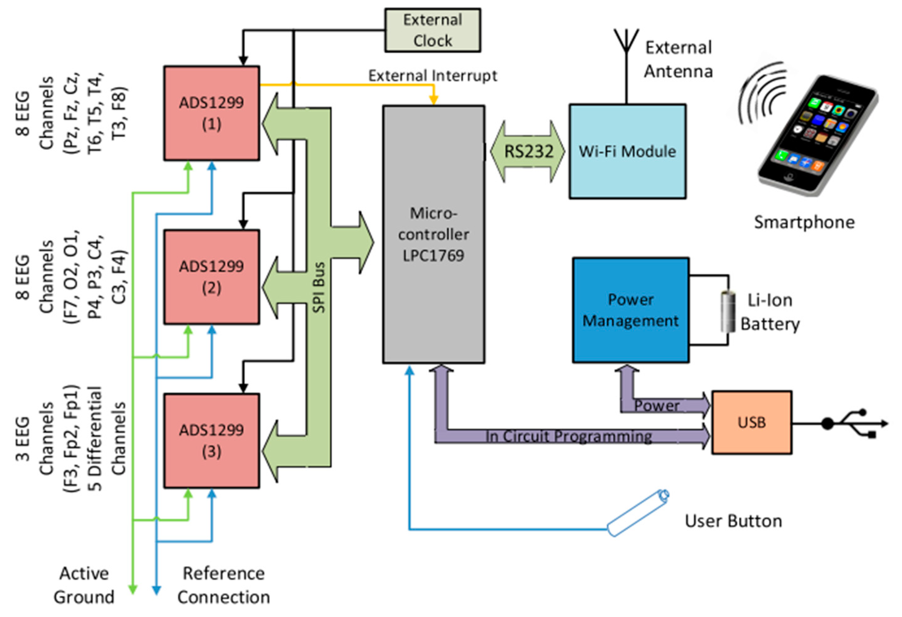
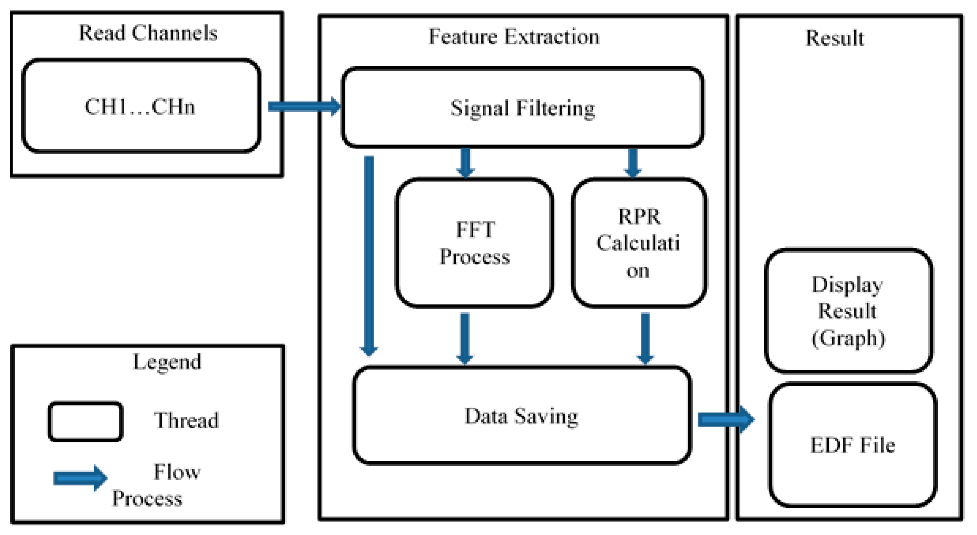
7.3. Application of AFEs for EEG Registration

AFEs have become widespread in the development of methods to remove and process an electroencephalographic signals. In the early 2010s, the main problem was the lack of a portable device that allowed accurate and reliable recording of the electrical activity of the brain accurately and reliably [148]. Computer-based multi-channel DAQ systems that existed at that time were cumbersome, expensive, or required design redundancy to achieve high reliability and high-speed acquisition [149,150]. Since 2014, the first portable and low-cost systems containing various types of AFEs at their core have appeared. For example, Acharya et al. suggested using a model that is a system for collecting data on biopotential based on ADS1299 AFE, which was specially created for the registration of brain activity signals [151]. The aim of some studies was to design, develop, and evaluate a general-purpose EEG acquisition system that can be easily integrated with different open-source programs [152,153,154,155], portable systems for continuous real-time recording of EEG signals [156,157,158,159], or even smartphone-based solutions.
This was the main task set by Bateson and Asghar in their study [160]. Their aim was to design a general-purpose EEG platform (smartphone-based EEG system) based on the ADS1299 AFE, with the capabilities of a smartphone that has the capacity to adapt to a range of specific research uses. Their target system was based on technical specifications and the 10–20 system configuration for clinical EEG devices, which involved developing a system using three combined ADS1299 ICs to form a 24-channel system with a resolution of 24 bits and sampling frequency of 250 Hz. The EEG system communicates with a smartphone (Android operating system) via Wi-Fi, with an application developed to have the core features of impedance checking, live data plotting, and data acquisition storage, as shown in Figure 18.
One of the most significant novel issues in the registration and processing of EEGs is the use of multi-channel techniques, which was covered in the article by W. Apriadi et al. [161]. This study was concerned with the development of an EEG acquisition and signal processing system by adding active electrodes and implementing multithread techniques. Active electrodes were used to reduce noise when transferring the signals from the electrode to the acquisition system. Verification was performed by comparing the active and passive electrodes using a NETECH MiniSIM EEG Simulator 330. The acquisition system was based on a Raspberry Pi and three ADS1299, with multithread signal treatment and signal filtering performed in different threads, and it placed all EEG features into the database. The EEG signal processing stage included fast Fourier transform (FFT), signal feature extraction, and signal analysis. These calculations are divided into several functionally independent computations, where each channel is calculated using different threads. The results of this study showed the effectiveness of the multithreaded method for processing large amounts of data (32 channels of 24-bit EEG signals) with low noise levels on the active electrodes. The multithread process is illustrated in Figure 19. The read channel thread is used for monitoring the ready data and acquisition of EEG signals from devices. The thread checks the validity of the EEG signals (status and channels) to filter the thread further and save the filtered signals. The results of this acquisition system can be exported to a European data format (EDF) file and displayed as graphics.

7.4. Application of AFEs for EMG Registration

Another biomedical signal recorded almost as often as electroencephalographic signals, judging by the material under review, is the electromyogram. However, interest in recording an electromyographic signal arose somewhat later than in recording an ECG or EEG. The most common designs focus on low-cost tools for EMG acquisition for diagnostic purposes in the neuromuscular system state [162,163,164,165], usually based on the ADS1298 AFE, especially for patients with amputated limbs. We can find examples of hybrid control circuits where the analog part concerns the amplification, filtering, and acquisition of EMGs, whereas the digital part focuses mainly on checking the signal levels and driving motor units [165,166,167,168]. Subsequently, a new approach emerged, representing digital controllers programmed with their own decision intelligence that could predict the motion intent of the amputee [167].
Pancholi and Joshi proposed one of these solutions in their research paper [165], and proposed a more accurate and high-speed architecture based on a CNN for EMG pattern recognition. To verify the performance in real time, a configurable EMG circuit based on ADS1298 with a digital signal processor (DSP) was used. This involved signal preprocessing and a machine-learning algorithm using Keras, which is a high-level TensorFlow for the development of deep-learning models.
In the proposed architecture, the electromyographic signal primarily undergoes a preprocessing stage, which includes two functions: multiplication of peaks and power (MPP), and multiplication of zero crossings and power (MZP). This preprocessing step makes the EMG signal stationary and reduces the size of the training dataset, with less neural information loss. The peaks of these parameters contain frequency information, and the zero-order moment comprises information regarding time without a frequency transformation. The network comprises six layers: three convolution layers, two fully connected layers, and one softmax layer. The output of the third convolution layer was 5 × 64 after global average pooling was applied between the third and fourth fully connected (FC) layers with a size of 512. Subsequently, an FC layer of size 128 was incorporated, followed by a softmax layer. As a result, the training accuracy reached ~ 98%, and the testing accuracy reached ~ 95%.
With the active development of bionic prostheses, there is a need to develop a portable device that allows doctors to judge the state of the neuromuscular system of a person with an amputated limb [169,170]. The latest papers have presented the design and implementation of algorithms for gesture recognition [171,172] and rehabilitation purposes [173].
The last paper by Alejandro Toro Ossaba et al. [173] presented the design and implementation of an open-source multichannel EMG armband for hand gesture recognition. The proposed system is based on an open-source, four-channel EMG armband with the capacity to communicate with external devices via a serial communication interface. In particular, the EMG armband was connected to a personal computer to plot the acquired signal in real time for the user. To enable communication between the armband and computer, a serial USB interface was used.
The EMG armband has two main stages: a conditioning stage designed to filter, amplify, and place the raw EMG signal at the optimal level values so that it can be acquired by the second stage and an acquisition stage in which the conditioned EMG signal is acquired by a microcontroller via an ADC. This microcontroller also allows the armband to communicate with external devices such as personal computers to retrieve the acquired signal. Finally, the bracelet was demonstrated to be a powerful tool when prompted to simultaneously acquire EMG signals at the same time from multiple channels. The bracelet was able to acquire the four signals and send them correctly to a PC to plot them. Furthermore, it is an open-source tool for EMG acquisition that can improve many people’s life conditions.

7.5. Application of AFEs for EOG Registration and Special Purposes

The least number of studies were related to the use of AFEs for the registration and processing of oculography signals [174,175]. One of them [174] was concerned with the development and testing of an algorithm that allowed recording the movements of the human eye when working with a virtual keyboard, allowing a paralyzed person to type text using only eye movements. The EOG is acquired by an indigenously developed acquisition system from particular positions on the face. The differential voltages between the two dots above and below the eye correspond to the vertical channel, which yields information about the blinking and vertical movement of the eyeball. Similarly, the differential voltage between the two dots to the left and right of the eye corresponds to the horizontal channel, which provides information regarding the horizontal movement of the eyeball. A wearable mask with thin copper plates (dry electrodes) attached at specific positions was designed to acquire the EOG. Both the horizontal and vertical channels were sampled and digitized at a rate of 250 Hz using ADS1299 as the analog front-end and an Arduino to communicate with the PC. The digitized data were streamed continuously to a PC via a serial USB interface for processing. On the receiver side, a processing (language)-based applet is designed to acquire, filter (passband:0.1–30 Hz), classify the data into commands, and send them to a virtual keyboard applet.
As for the original application, this is mainly material related to the development of devices that perform joint recording of biomedical signals, such as simultaneous recording of the ECG, EEG, and EMG [176,177,178] or rarer signals such as electrogastrography (EGG) [179,180], as well as comparisons of different approaches to recording and processing weak signals [181] and shielding from interference [182].
Komorowski et al. [179] presented an up-to-date biomedical device for the purpose of EGG acquisition. The authors have also developed a variety of tools for signal analysis. The use of radio communication simplifies the implementation of the device and improves the patient comfort during testing. This is due to the ADS1298 AFE device achieving the possibility of acquiring signals with a DC component (unfiltered), which is rather important for diagnostic purposes. The 24-bit resolution of the ADC ensures the high quality of the output signal and allows the extraction of a wide set of artifacts from the signal, which raises the quality of diagnoses. Digital post-filtering can be applied, which greatly simplifies the construction of the bioamplifier and reduces the production cost.
Most novel solutions are related to wearable electronics and active biosensors, such as the electronic-textile 12-lead equivalent diagnostic electrocardiograph [183], skin-mountable flexible sensor patches for monitoring swallowing function [184], and wireless motion sensor nodes [185].

8. Conclusions

It is rather difficult to present the entire history of bioamplifiers in a single review. Nevertheless, we attempt to at least briefly present the main milestones connected directly with the development of semiconductor electronics. Because the problems to be solved have changed insignificantly with time, technological progress has made a decisive contribution to the improvement of bioamplifier performance. First, there was a transition from vacuum tubes to discrete transistor circuits, followed by the advent of manufacturing technology to circuits on operational and instrumental amplifiers, and then a decrease in the technological process of manufacturing microcircuits, up to the appearance of integrated analog-digital solutions based on a sigma-delta ADC. As the characteristics of bioamplifiers improve, their size and power consumption decrease, which greatly accelerates the development of portable medical devices for recording bioelectric signals, such as electrocardiograms, electroencephalograms, and a number of others. Despite the obvious popularity of today’s integrated AFE solutions, circuits based on modern instrumental amplifiers, such as INA333 and AD8422, are still widely used in their original designs, as well as the long-time veteran AD620.
As for AFE-based solutions, in the analysis of more than 200 articles, of which half were selected for this review, the main area of their application was the development of various portable devices and algorithms for signal processing obtained with them. It is important to note that the emergence of AFEs for medical purposes has greatly simplified the task of researchers to create original devices for recording biological signals, reducing the need to develop the analog part of the device. As it seems to us, this is the reason why the number of studies focused on the application of signal processing algorithms, including those using machine learning, has multiplied. Another reason is the desire to develop cheaper devices because, in some cases, devices that register the electrical activity of various organs can be very expensive.
Considering all stages of bioamplifier development, we can conclude that many parameters, such as the common mode rejection ratio and input impedance, have not undergone significant changes because the times of integrated instrumental amplifiers and integrated AFE solutions are essentially built on known circuitry solutions. As confirmed by modern research, further development of bioamplifiers will follow the path of greater integration, where not only is the analog part for signal preprocessing and ADC is integrated on a single silicon chip, but the microcontroller, a low-power transceiver for information exchange, and a voltage converter to operate from the battery combined together are also integrated. A detailed novel structure was proposed in [186] as a fully integrated wireless ECG system-on-chip (SoC) for wearable solutions. Implemented in 0.13-µm complimentary MOS (CMOS) technology, the entire system consumes only 2.89 µW under a 1.2-V supply when transmitting raw ECG data. A fully integrated ECG SoC requires no external clocks or an off-chip antenna, making it a good candidate for low-cost and disposable wireless ECG patches, such as epidermal electronics.
Another mainstream methodology in the development of bioamplifiers has attempted to reduce power consumption, which is extremely important for the development of wearable medical electronics. Modern AFEs use low-noise and low-power circuit design methodologies and aggressive voltage scaling to satisfy both the low power consumption and input-referred noise requirements of biopotential signal acquisition systems. In [187], an AFE was implemented in a 130-nm CMOS process, and it had a measured tunable mid-band gain from 31 to 52 dB with tunable low-pass and high-pass corner frequencies. Under only a 0.5-V supply voltage, it consumed 68 nW of power was consumed with an input-referred noise of 2.8 µVrms and a power efficiency factor (PEF) of 3.9, which made it very suitable for energy-harvesting applications. Another approach [188] offers a reconfigurable AFE that exploits the inherent low activity and quasi-periodicity of biosignals to reduce power consumption. This is realized by an agile, on-the-fly dynamic noise-power trade-off performed over specific cardiac cycle regions, which is guided by a least mean squares (LMS)-based adaptive predictor, leading to approximately 2.5× data-dependent power savings. Implemented in 65-nm CMOS, the AFE has tunable performance, exhibiting an input-referred noise ranging from 2.38 to 3.64 µVrms while consuming 307–769 nW from a 0.8-V supply.
The AFE power supply is of particular importance, as the power supply quality and stability are critical for wearable and implantable biomedical applications, such as the power supply for a concept design of a wearable (15 mm × 15 mm) one-lead ECG front-end sensor device that simultaneously harvests power and communicates with external receivers when exposed to a suitable RF field [189]. Solutions allowing a radio-frequency energy-harvesting (RFEH) system with an increased harvested power density can also be added here. Nowadays, RFEH systems can produce an output power of ~423 μW for harvesting ambient RF energy [190], which provides excellent prospects for the development of wearable devices for biopotential recording.

Author Contributions

Conceptualization, A.V.B., T.V.S. and A.A.A.; methodology, A.V.B., T.V.S. and A.A.A.; article search and analysis, E.E.S., A.A.A. and T.V.S.; writing—original draft preparation, A.A.A., T.V.S. and E.E.S.; writing—review and editing, all authors; visualization, T.V.S. and A.A.A.; supervision, O.A.M.; project administration, O.A.M. and A.A.A. All authors have read and agreed to the published version of the manuscript.

Funding

This research received no external funding.

Acknowledgments

The authors express their sincere gratitude to their colleagues from the Ecological Physiology Department of the Federal State Budgetary Scientific Institution “Institute of Experimental Medicine” and Department of Bioengineering Systems of the Saint Petersburg Electrotechnical University “LETI” for their support and constant interest in this work.

Conflicts of Interest

The authors declare no conflict of interest.

References

  1. Cajavilca, C.; Varon, J.; Sternbach, G.L. Luigi Galvani and the foundations of electrophysiology. Resuscitation 2009, 80, 159–162. [Google Scholar] [CrossRef] [PubMed]
  2. Barold, S.S. Willem Einthoven and the Birth of Clinical Electrocardiography a Hundred Years Ago. Card. Electrophysiol. Rev. 2003, 7, 99–104. [Google Scholar] [CrossRef] [PubMed]
  3. Thakor, N.V. Bipotentials and Electrophysiology Measurement; Johns Hopkins School of Medicine: Baltimore, MD, USA, 2000. [Google Scholar]
  4. Caceres, C.A.; Dreifus, L.S. Clinical Electrocardiography and Computers; Academic Press: New York, NY, USA; London, UK, 1970. [Google Scholar]
  5. Tompkins, W.J.; Webster, J.G. Design of Microcomputer-Based Medical Instrumentation; Prentice-Hall, Inc.: Englewood, NJ, USA, 1981. [Google Scholar]
  6. GOST 60601-2-51-2008; Medical Electrical Equipment—Part 2-51. Particular Requirements for Safety, including Essential Performance, of Recording and Analyzing Single Channel and Multichannel Electrocardiographs. Standardinform: Moscow, Russia, 2009.
  7. IEC 60601-2-25:2011; Medical Electrical Equipment—Part 2-25: Particular Requirements for the Basic Safety and Essential Performance of Electrocardiographs. IEC: Geneva, Switzerland, 2011.
  8. Kligfield, P.; Gettes, L.S.; Bailey, J.J.; Childers, R.; Deal, B.J.; Hancock, E.W.; Van Herpen, G.; Kors, J.A.; Macfarlane, P.; Mirvis, D.M.; et al. Recommendations for the Standardization and Interpretation of the Electrocardiogram. Circulation 2007, 115, 1306–1324. [Google Scholar] [CrossRef] [Green Version]
  9. Samuel Seely. Electron-Tube Circuits; McGraw-Hill Book Company, Inc.: New York, NY, USA, 1950. [Google Scholar]
  10. Toennies, J.F. Amplifier. U.S. Patent 2147940, 18 October 1937. [Google Scholar]
  11. Noyce, R. Semiconductor Device-and-Lead Structure. U.S. Patent US2981877A, 30 July 1959. [Google Scholar]
  12. Adrian, E.D.; Matthews, B.H.C. The interpretation of potential waves in the cortex. J. Physiol. 1934, 81, 440–471. [Google Scholar] [CrossRef] [PubMed]
  13. Blumlein, A. Thermionic Valve Amplifying Circuit. U.S. Patent 2185367, 2 January 1937. [Google Scholar]
  14. Donaldson, P.E. Electronic Apparatus for Biological Research; Butterworths Scientific Publications: London, UK, 1958. [Google Scholar]
  15. Guha, S.K. Some Aspects of Medical Electronics. IETE J. Res. 1967, 13, 201–206. [Google Scholar] [CrossRef]
  16. Livenson, A.R. Electromedical Apparatus; Medicine: Moscow, Russia, 1975. [Google Scholar]
  17. Smith, J.R., Jr. New Low-Level A-C Amplifier Provides Adjustable Noise Cancellation and Automatic Temperature Compensation. NASA Tech Brief. Brief 63-10003, March 1964. Available online: https://core.ac.uk/reader/10244550 (accessed on 29 June 2022).
  18. Fontenier, G. A sensitive, high impedance cardiac rhythm follower. Med. Biol. Eng. Comput. 1972, 10, 175–178. [Google Scholar] [CrossRef]
  19. Verigo, N.I.; Olifer, B.M.; Savelyev, V.I.; Sherman, A.M. PEKS-01 Portable Electrocardioscope. Transl. Meditsinskaya Tekhnika 1972, 3, 57–59. [Google Scholar] [CrossRef]
  20. Furman, K.I.; Lupu, N.Z. Cardiac monitoring and telemetering system. J. Appl. Physiol. 1963, 18, 840–842. [Google Scholar] [CrossRef]
  21. Unzhin, R.V.; Rozenblat, V.V. A transistor device for remote recording of heart rate, respiration, and movements. Transl. Bull. Eksperimental’noi Biol. Meditsiny 1964, 57, 117–120. [Google Scholar] [CrossRef]
  22. Super Matched Bipolar Transistor Pair Sets New Standards for Drift and Noise. National Semiconductor Application Note 222. 1979. Available online: https://www.ti.com/lit/an/snoa626b/snoa626b.pdf?ts=1658742009874&ref_url=https%253A%252F%252Fwww.google.com.hk%252F (accessed on 29 June 2022).
  23. Holmer, N.-G.; Lindstrom, K. An Electrometer Amplifier with Low Input Capacitance and Large Input Dynanic Range. IEEE Trans. Biomed. Eng. 1972, BME-19, 162–164. [Google Scholar] [CrossRef]
  24. Cox, J.W., Jr.; Laughter, J.S., Jr.; Brandon, C.W., III; Keller, F.W.; Dowdie, R.F.; Phillips, H.A.; Mirvis, D.M. A system oriented electrocardiographic amplifier. Cardiovasc. Res. 1979, 13, 238–241. [Google Scholar] [CrossRef] [PubMed]
  25. INA134 Audio Differential Line Receiver. Burr-Brown Corporation Data Sheet PDS-1390A. 1997. Available online: https://www.ti.com/lit/ds/symlink/ina134.pdf?ts=1658673414565 (accessed on 29 June 2022).
  26. Carter, B.; Mancini, R. Op Amps for Everyone, 5th ed.; Newnes: Cambridge, MA, USA, 2017; p. 484. [Google Scholar]
  27. Gudaitis, A.M. Virtual Right Leg Drive and Augmented Right Leg Drive Circuits for Common Mode Voltage Reduction in ECG and EEG Measurements. U.S. Patent 5,392,784, 28 February 1995. [Google Scholar]
  28. Wayne, S. Finding the Needle in a Haystack: Measuring small differential voltages in the presence of large common-mode voltages. Analog. Dialogue 2000, 34, 34-01. [Google Scholar]
  29. Beerwinkle, K.R.; Burch, J.J. A Low-Power Combination Electrocardiogram-Respiration Telemetry Transmitter. IEEE Trans. Biomed. Eng. 1976, BME-23, 484–486. [Google Scholar] [CrossRef] [PubMed]
  30. Oberg, T. A Circuit for Contact Monitoring in Electrocardiography. IEEE Trans. Biomed. Eng. 1982, 29, 361–364. [Google Scholar] [CrossRef]
  31. Breuer, D. Some techniques for precision monolithic circuits applied to an instrumentation amplifier. IEEE J. Solid-State Circuits 1968, 3, 331–341. [Google Scholar] [CrossRef]
  32. Huijsing, J.H. Instrumentation amplifiers: A comparative study on behalf of monolithic integration. IEEE Trans. Instrum. Meas. 1976, IM-25, 227–231. [Google Scholar] [CrossRef]
  33. Smither, M.; Pugh, D.; Woolard, L.C.M.R.R. analysis of the 3-op-amp instrumentation amplifier. Electron. Lett. 1977, 13, 594–599. [Google Scholar] [CrossRef]
  34. Brokaw, P.; Timko, M.P. An improved monolithic instrumentation amplifier. IEEE J. Solid-State Circuits 1975, 10, 417–423. [Google Scholar] [CrossRef]
  35. Krabbe, H. Monolithic Data Amplifier. Differential instrumentation amplifier on a single chip has high input impedance, single-resistor gain adjustment, adjustable output bias, output-current sensing. Analog Dialogue 1972, 6, 3–5. [Google Scholar]
  36. Greef, R. Instruments for us in electrode process research. J. Phys. E Sci. Instrum. 1978, 11, 1–12. [Google Scholar] [CrossRef] [Green Version]
  37. Bergey, G.E.; Squires, R.D.; Sipple, W.C. Electrocardiogram Recording with Pasteless Electrodes. IEEE Trans. Biomed. Eng. 1971, BME-18, 206–211. [Google Scholar] [CrossRef]
  38. James, G.W.; Paul, M.H.; Wessel, H.U. Precision digital heart rate meter. J. Appl. Physiol. 1972, 32, 718–723. [Google Scholar] [CrossRef] [PubMed]
  39. Thakor, N.V.; Webster, J.G. Ground-Free ECG Recording with Two Electrodes. Biomed. Eng. 1980, BME-27, 699–704. [Google Scholar] [CrossRef] [PubMed]
  40. Arnett, D.W. Development of Modular Laboratory Equipment for Instruction in Biomedical Instrumentation. IEEE Trans. Biomed. Eng. 1978, BME-25, 441–445. [Google Scholar] [CrossRef] [PubMed]
  41. Webster, J.G.; Nimunkar, A.J.; Powell, R. Medical Instrumentation. In Application and Design, 5th ed.; Wiley: Hoboken, NJ, USA, 2018. [Google Scholar]
  42. Virtanen, J.; Parkkonen, L.; Ilmoniemi, R.J.; Pekkonen, E.; Näätänen, R. Biopotential amplifier for simultaneous operation with biomagnetic instruments. Med. Biol. Eng. Comput. 1997, 35, 402–408. [Google Scholar] [CrossRef] [PubMed]
  43. Yoo, S.K.; Kim, N.H.; Kim, S.H.; Kim, J.L. The development of high precision EEG amplifier for the computerized EEG analysis. In Proceedings of the 17th International Conference of the Engineering in Medicine and Biology Society, Montreal, QC, Canada, 20–23 September 1995; Volume 2, pp. 1651–1652. [Google Scholar]
  44. Badillo, L.; Leija, L.; Valentino, A.; Gutierrez, J.; Igartua, L.; Hernandez, P.; Alvarado, C. Sixteen channels Holter to EEG signal. In Proceedings of the 19th Annual International Conference of the IEEE Engineering in Medicine and Biology Society, Chicago, IL, USA, 30 October–2 November 1997; Volume 4, pp. 1472–1473. [Google Scholar]
  45. Reske, D.; Moussavi, Z. Design of a web-based remote heart-monitoring system. In Proceedings of the Second Joint 24th Annual Conference and the Annual Fall Meeting of the Biomedical Engineering Society, Houston, TX, USA, 23–26 October 2002; Volume 3, pp. 1847–1848. [Google Scholar]
  46. Van Doren, C.L. Grasp Stiffness as a Function of Grasp Force and Finger Span. Motor Control 1998, 2, 352–378. [Google Scholar] [CrossRef] [PubMed]
  47. Scott, T.D.; Peckham, P.H.; Kilgore, K.L. Tri-state myoelectric control of bilateral upper extremity neuroprostheses for tetraplegic individuals. IEEE Trans. Rehabil. Eng. 1996, 4, 251–263. [Google Scholar] [CrossRef]
  48. Wisana, I.D.G.; Nugraha, P.; Rachman, R. Development of a Low-Cost and Effisient ECG devices with IIR Digital Filter Design. Indones. J. Electron. Electromed. Eng. Med. Inform. 2021, 3, 21–28. [Google Scholar]
  49. Farooq, A.; Aroos, S.; Mumtaz, L.; Mazhar, M.; Baig, N.A.; Jafri, I.; Khaliq, A. Low-Cost Portable ECG Monitoring Device for Inaccessible Areas in Pakistan. Sir Syed Univ. Res. J. Eng. Technol. 2022, 12, 8–13. [Google Scholar] [CrossRef]
  50. Triwiyanto, E.Y.; Lamidi, M.R.M. Recent Technology and Challenge in ECG Data Acquisition Design: A Review. In Proceedings of the 2021 International Seminar on Application for Technology of Information and Communication (iSemantic), Semarangin, Indonesia, 18–19 September 2021; pp. 144–150. [Google Scholar] [CrossRef]
  51. Faruk, N.; Abdulkarim, A.; Emmanuel, I.; Folawiyo, Y.Y.; Adewole, K.S.; Mojeed, H.A.; Oloyede, A.A.; Olawoyin, L.A.; Sikiru, I.A.; Nehemiah, M.; et al. A comprehensive survey on low-cost ECG acquisition systems: Advances on design specifications, challenges and future direction. Biocybern. Biomed. Eng. 2021, 41, 474–502. [Google Scholar] [CrossRef]
  52. Hartmann, E. ECG Front-End Design is Simplified with MicroConverter. Analog Dialogue 2003, 37, 1–5. [Google Scholar]
  53. Li, G.; Wang, L.L.; Wang, Y.; Lin, L.; Jiang, W.; Lu, S.C.; Besio, W.G. A new kind of monitor for ophthalmic operation. J. Phys. Conf. Ser. 2005, 13, 345–348. [Google Scholar] [CrossRef]
  54. Kolasa, B.; Holt, H.; Duff, M. Discussion Between CareFusionand Analog Devices: Optimizing Performance and Lowering Power in an EEG Amplifier. Analog Devices Tech. Artic. 2011, MS-217, 1–5. [Google Scholar]
  55. Jin-ling, Z.; Lei, S.; Ya-chi, W.; Zhi-chen, Z. An ECG 7-lead monitoring system designing based on lower-power. In Proceedings of the ICME International Conference on Complex Medical Engineering, Beijing, China, 25–28 May 2013; pp. 154–159. [Google Scholar]
  56. Yang, G.; Su, X.; Zhao, L.; Cui, S.; Meng, Q.; Pei, W.; Chen, H. Research of portable community-oriented health monitoring terminal. In Proceedings of the 8th World Congress on Intelligent Control and Automation, Jinan, China, 7–9 July 2010; pp. 2979–2984. [Google Scholar]
  57. Wu, C.; Li, G.; Pommerenke, D.J.; Khilkevich, V.; Hess, G. Characterization of the RFI Rectification Behavior of Instrumentation Amplifiers. In Proceedings of the IEEE Symposium on Electromagnetic Compatibility, Signal Integrity and Power Integrity (EMC, SI & PI), Long Beach, CA, USA, 30 July–3 August 2018; pp. 156–160. [Google Scholar]
  58. Wu, Z.; Liu, J.; Ma, J. A novel cranial electrotherapy stimulation system with arbitrary waveform stimulation. In Proceedings of the 7-th International Conference on Biomedical Engineering and Informatics, Dalian, China, 14–16 October 2014; pp. 517–521. [Google Scholar]
  59. Petkos, K.; Koutsoftidis, S.; Guiho, T.; Degenaar, P.; Jackson, A.; Greenwald, S.E.; Brown, P.; Denison, T.; Drakakis, E.M. A high-performance 8 nV/√Hz 8-channel wearable and wireless system for real-time monitoring of bioelectrical signals. J. Neuroeng. Rehabil. 2019, 16, 156. [Google Scholar] [CrossRef]
  60. Babušiak, B.; Borik, Š. Bio-Amplifier with programmable gain and adjustable leads. In Proceedings of the 36th International Conference on Telecommunications and Signal Processing (TSP), Rome, Italy, 2–4 July 2013; pp. 616–619. [Google Scholar]
  61. Babusiak, B.; Borik, S.; Gala, M. Bio-amplifier with Programmable Gain and Adjustable Leads for Basic Measurement of Bioelectric Signals. In Information Technologies in Biomedicine; Advances in Intelligent Systems and Computing, Volume 284; Piętka, E., Kawa, J., Wieclawek, W., Eds.; Springer: Cham, Switzerland, 2014; Volume 4. [Google Scholar]
  62. Joshi, S.; Wakankar, A.; Khambete, N. Design and implementation of low power compact amplifier circuitry for wearable biosignal device. In Proceedings of the International Conference on Computing Communication Control and automation (ICCUBEA), Pune, India, 12–13 August 2016. [Google Scholar]
  63. Wang, Y.; Wunderlich, R.; Heinen, S. A low noise wearable wireless ECG system with body motion cancellation for long term homecare. In Proceedings of the IEEE 15th International Conference on e-Health Networking, Applications and Services (Healthcom 2013), Lisbon, Portugal, 9–12 October 2013; pp. 507–511. [Google Scholar]
  64. Chen, X.; Wang, Z.J. Design and Implementation of a Wearable, Wireless EEG Recording System. In Proceedings of the 5th International Conference on Bioinformatics and Biomedical Engineering, Wuhan, China, 10–12 May 2011. [Google Scholar]
  65. Abhishek, B.; Poojary, A.G.; Rao, M.V.A.; Narayanan, S. Low Power Portable EEG for Continuous Monitoring with Active Electrodes. In Proceedings of the Texas Instruments India Educators’ Conference, Bangalore, India, 4–6 April 2013; pp. 332–339. [Google Scholar]
  66. Puyol, R.; Lenzi, G.; Barg, G.; Arnaud, A. A portable, high density EEG acquisition system. In Proceedings of the 7th Argentine School of Micro-Nanoelectronics, Technology and Applications, Buenos Aires, Argentina, 15–16 August 2013; pp. 32–37. [Google Scholar]
  67. Valle, B.G.D.; Cash, S.S.; Sodini, C.G. Wireless behind-the-ear EEG recording device with wireless interface to a mobile device (iPhone/iPod touch). In Proceedings of the 36th Annual International Conference of the IEEE Engineering in Medicine and Biology Society, Chicago, IL, USA, 26–30 August 2014; pp. 5952–5955. [Google Scholar]
  68. Rai, K.; Thakur, K.K.; Mane, P.K.; Panigrahi, N. Designing Low Cost Yet Robust EEG Acquisition System. In Proceedings of the IEEE International Symposium on Smart Electronic Systems (iSES) (Formerly iNiS), Rourkela, India, 16–18 December 2019; pp. 390–395. [Google Scholar]
  69. Sarhang-Nejad, M.; Temes, G.C. A high-resolution multibit Sigma Delta ADC with digital correction and relaxed amplifier requirements. IEEE J. Solid-State Circuits 1993, 28, 648–660. [Google Scholar] [CrossRef]
  70. Aziz, P.M.; Sorensen, H.V.; Vn der Spiegel, J. An overview of sigma-delta converters. IEEE Signal Process. Mag. 1996, 13, 61–84. [Google Scholar] [CrossRef]
  71. McKee, J.J.; Evans, N.E.; Wallace, D. Sigma-delta analogue-to-digital converters for ECG signal acquisition. In Proceedings of the 18th Annual International Conference of the IEEE Engineering in Medicine and Biology Society, Amsterdam, Netherlands, 31 October–3 November 1996; Volume 1, pp. 19–20. [Google Scholar]
  72. Berry, D.; Duignan, F.; Hayes, R. An Investigation of the use of a High Resolution ADC as a “Digital Biopotential Amplifier”. In Proceedings of the 4th European Conference of the International Federation for Medical and Biological Engineering, IFMBE, Antwerp, Belgium, 23–27 November 2008; Vander Sloten, J., Verdonck, P., Nyssen, M., Haueisen, J., Eds.; Springer: Berlin/Heidelberg, Germany, 2009; Volume 22. [Google Scholar]
  73. Lie, D.; Das, V.; Hu, W.; Liu, Y.; Nguyen, T. A Low-Power CMOS Analog Front-End IC with Adjustable On-Chip Filters for Biosensors. Open J. Appl. Biosens. 2013, 2, 104–111. [Google Scholar] [CrossRef]
  74. Chou, S.T.; Huang, S.H.; Hong, Z.H.; Chen, W. A 40 Gbps optical receiver analog front-end in 65 nm CMOS. In Proceedings of the IEEE International Symposium on Circuits and Systems (ISCAS), Seoul, Korea, 20–23 May 2012; pp. 1736–1739. [Google Scholar]
  75. Hwang, Y.; Lin, H. A New CMOS Analog Front End for RFID Tags. IEEE Trans. Ind. Electron. 2009, 56, 2299–2307. [Google Scholar] [CrossRef]
  76. Ng, K.A.; Chan, P.K. A CMOS analog front-end IC for portable EEG/ECG monitoring applications. IEEE Trans. Circuits Syst. I Regul. Pap. 2005, 52, 2335–2347. [Google Scholar] [CrossRef]
  77. Kim, Y.J.; Cho, S.E.; Um, J.Y.; Chae, M.K.; Bang, J.; Song, J.; Jeon, T.; Kim, B.; Sim, J.Y.; Park, H.J. A Single-Chip 64-Channel Ultrasound RX-Beamformer Including Analog Front-End and an LUT for Non-Uniform ADC-Sample-Clock Generation. IEEE Trans. Biomed. Circuits Syst. 2017, 11, 87–97. [Google Scholar] [CrossRef]
  78. Yoon, Y.; Duan, Q.; Yeo, J.; Roh, J.; Kim, J.; Kim, D. A Delta–Sigma Modulator for Low-Power Analog Front Ends in Biomedical Instrumentation. IEEE Trans. Instrum. Meas. 2016, 65, 1530–1539. [Google Scholar] [CrossRef]
  79. Soundarapandian, K.; Berarducci, M. Analog Front-End Design for ECG Systems Using Delta-Sigma ADCs. Texas Instruments application Report 2010. Available online: https://www.ti.com/lit/an/sbaa160a/sbaa160a.pdf?ts=1658751056068&ref_url=https%253A%252F%252Fwww.google.com.hk%252F (accessed on 29 June 2022).
  80. Seidl, M. Analog Front-End Design with Texas Instruments’ Tooling Landscape. Application Note SBAA534—2022. Available online: https://www.ti.com/lit/an/sbaa534/sbaa534.pdf?ts=1658745163170&ref_url=https%253A%252F%252Fwww.google.com.hk%252F (accessed on 29 June 2022).
  81. ADS129x Low-Power, 8-Channel, 24-Bit Analog Front-End for Biopotential Measurements. Texas Instruments Data sheet SBAS459K–JANUARY 2010–REVISED AUGUST 2015. Available online: https://www.ti.com/lit/ds/symlink/ads1296r.pdf (accessed on 29 June 2022).
  82. MAX30003 Ultra-Low Power, Single-Channel Integrated Biopotential (ECG, R-to-R Detection) AFE, Maxim Integrated Data Sheet 19-8558; Rev 2; 9/2019. Available online: https://www.stg-maximintegrated.com/en/products/analog/data-converters/analog-front-end-ics/MAX30003.html (accessed on 29 June 2022).
  83. ADAS1000-3/ADAS1000-4 Low Power, Three Electrode Electrocardiogram (ECG) Analog Front End. Analog Devices Data Sheet D10997-0-1/2015(B). Available online: https://www.analog.com/media/en/technical-documentation/data-sheets/adas1000-3_1000-4.pdf (accessed on 29 June 2022).
  84. AD8232 Single-Lead, Heart Rate Monitor Front End. Analog Devices Data Sheet D10866-0-6/2018(C). Available online: https://www.analog.com/media/en/technical-documentation/data-sheets/ad8232.pdf (accessed on 29 June 2022).
  85. Vijay, V.; Reddy, C.V.S.K.; Pittala, C.S.; Vallabhuni, R.R.; Saritha, M.; Lavanya, M.; Venkateswarlu, S.C.; Sreevani, M. ECG performance validation using operational transconductance amplifier with bias current. Int. J. Syst. Assur. Eng. Manag. 2021, 12, 1173–1179. [Google Scholar] [CrossRef]
  86. Lu, T.C.; Liu, P.; Gao, X.; Lu, Q.Y. A Portable ECG Monitor with Low Power Consumption and Small Size Based on AD8232 Chip. Mech. Mater. 2014, 513–517, 2884–2887. [Google Scholar] [CrossRef]
  87. Huda, N.; Khan, S.; Abid, R.; Shuvo, S.B.; Labib, M.M.; Hasan, T. A Low-cost, Low-energy Wearable ECG System with Cloud-Based Arrhythmia Detection. In Proceedings of the IEEE Region 10 Symposium (TENSYMP), Dhaka, Bangladesh, 5–7 June 2020; pp. 1840–1843. [Google Scholar]
  88. Sani, S. Design and Implementation of a Low-Cost ECG Monitoring System Using ARM Cortex-M4 Family Microcontroller. In Proceedings of the IEEE International Conference on Consumer Electronics (ICCE), Las Vegas, NV, USA, 10–12 January 2021. [Google Scholar]
  89. Briginetsa, S.; Volkov, A.; Martinov, G.; Veselkov, A. Development of a mobile heart monitor based on the ECG module AD8232. Am. Inst. Phys. 2015, 10, 1–7. [Google Scholar]
  90. Gifari, M.W.; Zakaria, H.; Mengko, R. Design of ECG Homecare:12-Lead ECG Acquisition using Single Channel ECG Device Developed on AD8232 Analog Front End. In Proceedings of the 5-th International Conference on Electrical Engineering and Informatics, Denpasar, Indonesia, 10–11 August 2015; pp. 371–376. [Google Scholar]
  91. Agung, M.A.; Basari. 3-lead acquisition using single channel ECG device developed on AD8232 analog front end for wireless ECG application. AIP Conf. Proc. 2017, 1817, 040015. [Google Scholar]
  92. Yusof, M.A.; Hau, Y.W. Mini Home-Based Vital Sign Monitor with Android Mobile Application (my Vital Gear). In Proceedings of the IEEE-EMBS Conference on Biomedical Engineering and Science (IECBES), Sarawak, Malaysia, 3–6 December 2018; pp. 150–155. [Google Scholar]
  93. Kanani, P.; Padole, M. Recognizing Real Time ECG Anomalies Using Arduino, AD8232 and Java; Springer Nature: Singapore, 2018; Volume 905, pp. 54–64. [Google Scholar]
  94. Iskandar, W.J.; Roihan, I.; Koestoer, R.A. Prototype low-cost portable electrocardiogram (ECG) based on Arduino-Uno with Bluetooth feature. AIP Conf. Proc. 2019, 2193, 050019. [Google Scholar]
  95. Rahman, M.M.; Rimon, M.A.; Hoque, M.A.; Sammir, M.R. Affordable Smart ECG Monitoring Using Arduino & Bluetooth Module. In Proceedings of the 1st International Conference on Advances in Science, Engineering and Robotics Technology, Dhaka, Bangladesh, 3–5 May 2019. [Google Scholar]
  96. Çelebi, M. Portable ECG Monitoring Device Design Based on ARDUINO. In Proceedings of the Medical Technologies Congress (TIPTEKNO), Antalya, Turkey, 19–20 November 2020. [Google Scholar]
  97. Hamad, A.M.; Jasim, A.D. Jasim Remote ECG signal monitoring and classification based on Arduino with AD8232 sensor. Univ. Thi-Qar J. Eng. Sci. 2021, 11, 95–101. [Google Scholar]
  98. Patil, P.; Bhole, K. Real time ECG on internet using Raspberry Pi. In Proceedings of the International Conference on Communication, Computing and Internet of Things (IC3IoT), Chennai, India, 15–17 February 2018; pp. 267–270. [Google Scholar]
  99. Lili, T.; Wei, H. Portable ECG Monitoring System Design. In Proceedings of the 3rd International Conference on Electronic Information Technology and Computer Engineering (EITCE), Xiamen, China, 18–20 October 2019; pp. 1370–1373. [Google Scholar]
  100. Bravo-Zanoguera, M.; Cuevas-González, D.; García-Vázquez, J.P.; Avitia, R.L.; Reyna, M.A. Portable ECG System Design Using the AD8232 Microchip and Open-Source Platform. Multidiscip. Digit. Publ. Inst. Proc. 2019, 42, 49. [Google Scholar]
  101. Bravo-Zanoguera, M.; Cuevas-González, D.; Reyna, M.A.; García-Vázquez, J.P.; Avitia, R.L. Fabricating a Portable ECG Device Using AD823X Analog Front-End Microchips and Open-Source Development Validation. Sensors 2020, 20, 5962. [Google Scholar] [CrossRef]
  102. Kusumah, I.H.; Artiyasa, M.; Al-Bukhori; Khoiri, M.I.; Ramadhan, A.D.; Supiyandi. Blood Pressure Measurement using Wrist PPG and ECG. In Proceedings of the 6th International Conference on Computing Engineering and Design, Sukabumi, Indonesia, 15–16 October 2020. [Google Scholar]
  103. Chatterjee, A.; Pal, S.; Mitra, M. PPT Based Portable Cuffless Systolic Blood Pressure Estimation. In Proceedings of the Calcutta Conference (CALCON), Kolkata, India, 28–29 February 2020; pp. 142–147. [Google Scholar]
  104. Ji, X.; Ning, C.; Zhao, C.; Zhang, X. Design of the HRV Analysis System Based on AD8232. In Proceedings of the 3rd International Symposium on Mechatronics and Industrial Informatics (ISMII 2017), Zhuhai, China, 30–31 October 2015; pp. 230–234. [Google Scholar]
  105. Abidin, Z.; Siwindarto, P.; Muttaqin, A. Portable Heart Beat Monitoring System Using Three-Lead Configuration. In Proceedings of the Electrical Power, Electronics, Communications, Controls and Informatics Seminar (EECCIS), Batu, Indonesia, 9–11 October 2018; pp. 173–176. [Google Scholar]
  106. Potdar, R.M.; Meshram, M.R.; Kumar, R. Heart Rate Monitoring with Real Time ECG using AD-8232. Int. J. Res. Anal. Rev. (IJRAR) 2019, 2661, 699–705. [Google Scholar]
  107. Turner, J.; Zellner, C.; Khan, T.; Yelamarthi, K. Continuous heart rate monitoring using smartphone. In Proceedings of the IEEE International Conference on Electro Information Technology (EIT), Lincoln, NE, USA, 14–17 May 2017; pp. 324–326. [Google Scholar]
  108. Utomo, T.P.; Nuryani, N. QRS peak detection for heart rate monitoring on Android smartphone. In Proceedings of the International Conference on Science and Applied Science, Qingdao, China, 29–30 July 2017. [Google Scholar]
  109. Wang, Z.; Wang, F.; Ji, X. Analysis of Autonomic Nervous System Based on HRV. In Proceedings of the 4th International Conference on Mechanical, Control and Computer Engineering (ICMCCE), Hohhot, China, 24–26 October 2019; pp. 309–314. [Google Scholar]
  110. Hendra, M.; Kurniawan, D.; Chrismiantari, R.V.; Utomo, T.P.; Nuryani, N. Drowsiness detection using heart rate variability analysis based on microcontroller unit. In Proceedings of the 9th International Conference on Physics and Its Applications (ICOPIA), Surakarta, Indonesia, 14 August 2018. [Google Scholar]
  111. Chhabra, M.; Kalsi, M. Real Time ECG monitoring system based on Internet of Things (IoT). Int. J. Sci. Res. Publ. 2017, 7, 547–550. [Google Scholar]
  112. Mishra, A.; Chakraborty, B. AD8232 based Smart Healthcare System using Internet of Things (IoT). Int. J. Eng. Res. Technol. (IJERT) 2018, 7, 13–16. [Google Scholar]
  113. Bhosale, V.K.; Bhosale, K.R. Healthcare Based on IoT using Arduino and AD8232 Hearth Rate Monitoring Chip. Asian J. Converg. Technol. 2017, 3, 1–12. [Google Scholar]
  114. Pereira, M.; Nagapriya, K.K. A Novel IoT Based Health Monitoring System Using LPC2129. In Proceedings of the 2nd IEEE International Conference on Recent Trends in Electronics Information & Communication Technology (RTEICT), Bangalore, India, 19–20 May 2017; pp. 564–568. [Google Scholar]
  115. Rajanna, R.R.; Natarajan, S.; Vittal, P.R. An IoT Wi-Fi Connected Sensor for Real Time Heart Rate Variability Monitoring. In Proceedings of the IEEE Third International Conference on Circuits, Control, Communication and Computing, Bangalore, India, 3–5 October 2018. [Google Scholar]
  116. Sharma, A.K.; Saini, L.M. IoT based Diagnosing Myocardial Infarction through Firebase Web Application. In Proceedings of the Third International Conference on Electronics Communication and Aerospace Technology [ICECA 2019], Coimbatore, India, 12–14 June 2019; pp. 190–195. [Google Scholar]
  117. Ghifari, A.F.; Perdana, R.S. Minimum System Design of The IoT-Based ECG Monitoring. In Proceedings of the International Conference on ICT for Smart Society (ICISS), Bandung, Indonesia, 19–20 November 2020. [Google Scholar]
  118. Kubov, V.I.; Dymytrov, Y.Y.; Stojanović, R.; Kubova, R.M.; Škraba, A. A Feasible IoT System for Monitoring PPG and ECG Signals by using Low-cost Systems-on-chips and HTML Interface. In Proceedings of the 9th Mediterranean Conference on Embedded Computing (MECO), Budva, Montenegro, 8–11 June 2020. [Google Scholar]
  119. Yol, Y.; Ozdemir, M.A.; Akan, A. Design of Real Time Cardiac Arrhythmia Detection Device. In Proceedings of the Medical Technologies Congress (TIPTEKNO), Izmir, Turkey, 3–5 October 2019. [Google Scholar]
  120. Bhat, T.; Bhat, S.; Manoj, T. A Real-Time IoT Based Arrhythmia Classifier Using Convolutional Neural Networks. In Proceedings of the IEEE International Conference on Distributed Computing, VLSI, Electrical Circuits and Robotics (DISCOVER), Udupi, India, 30–31 October 2020; pp. 79–83. [Google Scholar]
  121. Moghadas, E.; Rezazadeh, J.; Farahbakhsh, R. An IoT Patient Monitoring based on Fog computing and Data Mining: Cardiac Arrhythmia Usecase. Internet Things 2020, 11, 100251. [Google Scholar] [CrossRef]
  122. Gowtham, A.; Anirudh, L.; Sreeja, B.S.; Aakash, B.A.; Adittya, S. Detection of Arrhythmia using ECG waves with Deep Convolutional Neural Networks. In Proceedings of the Fourth International Conference on Electronics, Communication and Aerospace Technology (ICECA-2020), Coimbatore, India, 5–7 November 2020; pp. 1390–1396. [Google Scholar]
  123. Simanjuntak, J.E.; Khodra, M.L.; Manullang, M.C. Design Methods of Detecting Atrial Fibrillation Using the Recurrent Neural Network Algorithm on the Arduino AD8232 ECG Module. In Proceedings of the Earth and Environmental Science, South Lampung, Indonesia, 25–26 October 2019. [Google Scholar]
  124. Abidin, Z.; Jaya, L.A.; Siwindarto, P.; Tanno, K. ECG Signal Processing Using Fuzzy Classification for Sudden Cardiac Death Prediction. In Proceedings of the 50th International Symposium on Multiple-Valued Logic (ISMVL), Miyazaki, Japan, 09–11 November 2020; pp. 111–116. [Google Scholar]
  125. Samson, V.R.; Sai, U.B.; Rao, P.M.; Eswar, K.K.; Kumar, S.P. Automatic Oxygen Level Control of Patient Using Fuzzy Logic and Arduino. In Proceedings of the International Conference on Big Data Analytics and computational Intelligence (ICBDACI), Chirala, Andhra Pradesh, India, 23–25 March 2017; pp. 98–102. [Google Scholar]
  126. Camacho-Perea, A.; Maya-Martinez, S.U.; Tovar-Corona, B.; Erick, D. Electrocardiographic Signal as a Biometric Feature. In Proceedings of the 14th International Conference on Electrical Engineering, Computing Science and Automatic Control (CCE), Mexico City, Mexico, 20–22 October 2017. [Google Scholar]
  127. Potdar, R.M.; Meshram, M.R.; Kumar, R. Implementation of AD8232 ECG Signal Classification Using Peak Detection Method for Determining RST Point. Indones. J. Artif. Intell. Data Min. (IJAIDM) 2019, 2, 61–66. [Google Scholar]
  128. Wang, X.; Li, X.; Leung, V.C. Artificial Intelligence-Based Techniques for Emerging Heterogeneous Network: State of the Arts, Opportunities, and Challenges. Artif. Intell. Enabled Netw. 2015, 3, 1379–1391. [Google Scholar] [CrossRef]
  129. Chowdhury, M.H.; Hossain, Q.D.; Saha, P.; Rahaman, M.M. Design, fabrication and performance evaluation of a three electrode ECG recorder. In Proceedings of the International Conference on Innovations in Science, Engineering and Technology (ICISET), Dhaka, Bangladesh, 28–29 October 2016. [Google Scholar]
  130. Rahman, M.A.; Samin, M.J.; Al Hasan, Z. Remote ECG Monitoring and Syncope Detection System Using Deep Learning. In Proceedings of the 2nd ICAICT, Dhaka, Bangladesh, 28–29 November 2020; pp. 201–206. [Google Scholar]
  131. Sugunakar, M.B.S.; Maruthy, K.N.; Srinivas, C.H.; Johnson, P. A comparative study between single lead AD8232 heart rate monitor and standard electrocardiograph to acquire electrocardiographic data for cardiac autonomic function testing. Indian J. Sci. Technol. 2021, 14, 534–540. [Google Scholar] [CrossRef]
  132. Sun, C.; Liao, J.; Wang, G.; Li, B.; Meng, M.Q. A Portable 12-Lead ECG Acquisition System. In Proceedings of the International Conference on Information and Automation, Yinchuan, China, 26–28 August 2013; pp. 368–373. [Google Scholar]
  133. Cristea, C.; Pasarica, A.; Andruseac, G.; Dionisie, B.; Rotariu, C. A Wireless ECG Acquisition Device for Remote Monitoring of Heart Rate and Arrhythmia Detection. In Proceedings of the 5th IEEE International Conference on E-Health and Bioengineering, Iasi, Romania, 19–21 November 2015. [Google Scholar]
  134. Du, L.; Yan, Y.; Wu, W.; Mei, Q.; Luo, Y.; Li, Y.; Wang, L. Towards a smart Holter system with high performance analogue front-end and enhanced digital processing. In Proceedings of the 35th Annual International Conference of the IEEE EMBS, Osaka, Japan, 3–7 July 2013; pp. 1210–1213. [Google Scholar]
  135. Que, C.; Liu, Q.; Ai, Q.; Chen, K. Design and realization of 12-lead electrocardiosignal acquisition and processing system. In Proceedings of the 13th International Computer Conference on Wavelet Active Media Technology and Information Processing (ICCWAMTIP), Chengdu, China, 16–18 December 2016; pp. 436–439. [Google Scholar]
  136. Gnecchi, J.A.G.; Herrejón, A.D.; Anguiano, A.D.; Patiño, A.M.; Espinoza, D.L. Advances in the Construction of ECG Wearable Sensor Technology: The ECG-ITM-05 eHealth Data Acquisition System. In Proceedings of the Ninth Electronics, Robotics and Automotive Mechanics Conference, Cuernavaca, Mexico, 19–23 November 2012; pp. 338–342. [Google Scholar]
  137. Malcangi, M. Acquisition and processing of the physiologic signal to prevent driving accidents. In Proceedings of the 6-th European Embedded Design in Education and Research, Milan, Italy, 11–12 September 2014; pp. 212–215. [Google Scholar]
  138. Barabino, G.; Pani, D.; Dessi, A.; Raffo, L. A Configurable biopotentials acquisition module suitable for fetal electrocardiography studies. In Proceedings of the International Conference on Big Data Analytics and computational Intelligence (ICBDACI), Turin, Italy, 7–9 May 2015; pp. 479–483. [Google Scholar]
  139. Wu, C.; Zhang, Y.; Hong, C.; Chiueh, H. Implementation of ECG Signal Processing Algorithms for Removing Baseline Wander and Electromyography Interference. In Proceedings of the 8th IEEE International Conference on Communication Software and Networks, Beijing, China, 4–6 June 2016; pp. 118–121. [Google Scholar]
  140. Talavera, J.R.; Mendoza, E.A.; Dávila, N.M.; Supo, E. Implementation of a real-time 60 Hz interference cancellation algorithm for ECG signals based on ARM cortex M4 and ADS1298. In Proceedings of the IEEE XXIV International Conference on Electronics, Electrical Engineering and Computing (INTERCON), Cusco, Peru, 15–18 August 2017. [Google Scholar]
  141. Martínez-Suárez, F.; Alvarado-Serrano, C. Prototype of an Ambulatory ECG Monitoring System with R Wave Detection in Real Time Based on FPGA. In Proceedings of the 16th International Conference on Electrical Engineering, Computing Science and Automatic Control (CCE), Mexico City, Mexico, 11–13 September 2019. [Google Scholar]
  142. Liu, J.; Zhou, Y. Design of a novel portable ECG monitor for heart health. In Proceedings of the Sixth International Symposium on Computational Intelligence and Design, Hangzhou, China, 28–29 October 2013; pp. 257–260. [Google Scholar]
  143. De Oliveira Igor, H.; Cene, V.H.; Balbinot, A. Portable electrocardiograph through android application. In Proceedings of the 37th Annual International Conference of the IEEE Engineering in Medicine and Biology Society (EMBC), Milan, Italy, 25–29 August 2015; pp. 6780–6783. [Google Scholar]
  144. Abtahi, F.; Snäll, J.; Aslamy, B.; Abtahi, S.; Seoane, F.; Lindecrantz, K. Biosignal PI, an Affordable Open-Source ECG and Respiration Measurement System. Sensors 2015, 15, 93–109. [Google Scholar] [CrossRef] [PubMed] [Green Version]
  145. Abtahi, F.; Aslamy, B.; Boujabir, I.; Seoane, F.; Lindecrantz, K. An Affordable ECG and Respiration Monitoring System Based on Raspberry PI and ADAS1000: First Step towards Homecare Applications. IFMBE Proc. 2015, 48, 5–8. [Google Scholar]
  146. Hafid, A.; Benouar, S.; Kedir-Talha, M.; Abtahi, F.; Attari, M.; Seoane, F. Full Impedance Cardiography Measurement Device Using Raspberry PI3 and System-on-Chip Biomedical Instrumentation Solutions. J. Biomed. Health Inform. 2018, 22, 1883–1894. [Google Scholar] [CrossRef]
  147. Přeučil, T.; Novotný, M. Low-Cost Portable ECG. In Proceedings of the 8th Mediterranean conference on embedded computing (MECO), Budva, Montenegro, 10–14 June 2019. [Google Scholar]
  148. Arulmozhivarman, P.; Reddy, G.R.; Tatavarti, R. Low-cost EEG Signal Acquisition System. In Proceedings of the ISSNIP Biosignals and Biorobotics Conference: Biosignals and Robotics for Better and Safer Living (BRC), Rio de Janeiro, Brazil, 18–20 February 2013. [Google Scholar]
  149. Liao, J.C.; Shih, W.Y.; Huang, K.J.; Fang, W.C. An online recursive ICA based real-time multichannel EEG system on chip design with automatic eye blink artifact rejection. In Proceedings of the International Symposium on VLSI Design, Automation, and Test (VLSI-DAT), Hsinchu, Taiwan, 22–24 April 2013. [Google Scholar]
  150. Chen, J.; Li, X.; Mi, X.; Pan, S. A High Precision EEG Acquisition System Based on the Compact PCI Platform. In Proceedings of the 7th International Conference on BioMedical Engineering and Informatics (BMEI 2014), Dalian, China, 14–16 October 2014; pp. 511–516. [Google Scholar]
  151. Acharya, D.; Rani, A.; Agarwal, S. EEG data acquisition circuit system Based on ADS1299EEG FE. In Proceedings of the 4th International Conference on Reliability, Infocom Technologies and Optimization (ICRITO) (Trends and Future Directions), Noida, India, 2–4 September 2015. [Google Scholar]
  152. Gani, H.S.; Wijaya, S.K.; La Ode Husein, Z.T. Development of EEG Data Acquisition System based on FPGA Zedboard. In Proceedings of the 5th International Conference on Instrumentation, Communications, Information Technology, and Biomedical Engineering (ICICI-BME), Bandung, Indonesia, 6–7 November 2017; pp. 246–250. [Google Scholar]
  153. Lee, S.; Shin, Y.; Kumar, A.; Kim, M.; Lee, H. Dry Electrode-based Fully Isolated EEG/fNIRS Hybrid Brain-monitoring System. IEEE Trans. Biomed. Eng. 2018, 66, 1055–1068. [Google Scholar] [CrossRef] [PubMed]
  154. Uktveris, T.; Jusas, V. Development of a Modular Board for EEG Signal Acquisition. In Proceedings of the 5th International Conference on Mathematics and Computers in Sciences and Industry (MCSI), Corfu, Greece, 25–27 August 2018; pp. 95–101. [Google Scholar]
  155. Wang, Z.; Li, W.; Chen, C.; Sun, C.; Chen, W. A multichannel reconfigurable EEG acquisition system design with felt-based soft material electrodes. In Proceedings of the International Instrumentation and Measurement Technology Conference (I2MTC), Houston, TX, USA, 14–17 May 2018. [Google Scholar]
  156. Zhao, Z.; Ivanov, K.; Lubich, L.; Mumin, O. Signal Quality and Electrode-Skin Impedance Evaluation in the Context of Wearable Electroencephalographic Systems. In Proceedings of the 40th Annual International Conference of the IEEE Engineering in Medicine and Biology Society (EMBC), Honolulu, HI, USA, 18–21 July 2018; pp. 4965–4968. [Google Scholar]
  157. Wang, Z.; Chen, C.; Li, W.; Yuan, W.; Han, T.; Sun, C.; Tao, L.; Zhao, Y. A Multichannel EEG Acquisition System with Novel Ag NWs/PDMS Flexible Dry Electrodes. In Proceedings of the 40th Annual International Conference of the IEEE Engineering in Medicine and Biology Society (EMBC), Honolulu, HI, USA, 18–21 July 2018; pp. 1299–1302. [Google Scholar]
  158. Gao, K.-P.; Shen, G.-C.; Zhao, N.; Jiang, C.-P. Wearable Multifunction Sensor for the Detection of Forehead EEG Signal and Sweat Rate on Skin Simultaneously. IEEE Sens. J. 2020, 20, 10393–10404. [Google Scholar] [CrossRef]
  159. Shen, P.; Liu, Y.; Xiong, W.; He, A.; Zhang, M. A Real-Time Impedance Measurement System for EEG Based on Embedded System. In Proceedings of the 13th International Congress on Image and Signal Processing, BioMedical Engineering and Informatics (CISP-BMEI), Chengdu, China, 17–19 October 2020; pp. 681–685. [Google Scholar]
  160. Bateson, A.D.; Asghar, A.U. Development and Evaluation of a Smartphone-Based Electroencephalography (EEG) System. IEEE Access 2021, 9, 75650–75667. [Google Scholar] [CrossRef]
  161. Apriadi, W.; Gani, H.S.; Prayitno, P.; Ibrahim, N.; Wijaya, S.K. Development of multithread acquisition system for high quality EEG signal measurement. J. Phys. Conf. Ser. 2021, 1816, 012072. [Google Scholar] [CrossRef]
  162. Tao, P.; Liu, W.; Tang, X. Human surface EHG acquisition and analysis system based on DM6446. In Proceedings of the International Conference on Medical Imaging Physics and Engineering, Shenyang, China, 19–20 October 2013; pp. 265–268. [Google Scholar]
  163. Mastinu, E.; Ortiz-Catalan, M.; Håkansson, B. Analog Front-Ends comparison in the way of a portable, low-power and low-cost EMG controller based on Pattern Recognition EMBC. In Proceedings of the 37th Annual International Conference of the IEEE Engineering in Medicine and Biology Society (EMBC), Milan, Italy, 25–29 August 2015; pp. 2111–2114. [Google Scholar]
  164. Mastinu, E.; Håkansson, B.; Ortiz-Catalan, M. Low-cost, open-source bioelectric signal acquisition system. In Proceedings of the 14th International Conference on Wearable and Implantable Body Sensor Networks (BSN), Eindhoven, Netherlands, 9–12 May 2017; pp. 19–22. [Google Scholar]
  165. Pancholi, S.; Joshi, A.M. Improved Classification Scheme using Fused Wavelet Packet Transform based Features for Intelligent Myoelectric Prostheses. IEEE Trans. Ind. Electron. 2020, 67, 8517–8525. [Google Scholar] [CrossRef]
  166. Zhou, R.; Wang, K.; Li, M. Design of a sEMG Signal Acquisition Instrument for Physical Rehabilitation Training. In Proceedings of the 10th International Symposium on Computational Intelligence and Design, Hangzhou, China, 9–10 December 2017; pp. 136–139. [Google Scholar]
  167. Favretto, M.A.; Cossul, S.; Andreis, F.R.; Balotin, A.F.; Marques, J.L.B. High Density Surface EMG System Based on ADS1298-front end. Lat. Am. Trans. 2018, 16, 1616–1622. [Google Scholar] [CrossRef]
  168. Ravariu, C.; Babarada, F.; Arhip, J.; Manea, E.; Pârvulescu, C. Personalized Mio-electrical Monitoring System Based on ADS1298 and MIM Electrodes. In Proceedings of the International Conference—10th Edition Electronics, Computers and Artificial Intelligence, Iasi, Romania, 28–30 June 2018. [Google Scholar]
  169. Zhao, Y.; Li, F.; Xu, L. A sEMG-Based Hand Motions Recognition System with Dimension-Reduced FFT. In Proceedings of the Chinese Control and Decision Conference (CCDC), Nanchang, China, 3–5 June 2019; pp. 1415–1420. [Google Scholar]
  170. De Jager, K.; Mentink, M.; Lancashire, H.; Al-Aja, Y. Characterization of a multi-channel multiplexed EMG recording system: Towards realizing variable electrode configurations. In Proceedings of the IEEE Biomedical Circuits and Systems Conference (BioCAS), Nara, Japan, 17–19 October 2019. [Google Scholar]
  171. Pancholi, S.; Joshi, A.M. Electromyography-Based Hand Gesture Recognition System for Upper Limb Amputees. IEEE Sens. Lett. 2019, 3, 5500304. [Google Scholar] [CrossRef]
  172. Pancholi, S.; Joshi, A.M. A Fast and Accurate Deep learning framework for EMG-PR based Upper-limb Prosthesis Control. In Proceedings of the International Symposium on Smart Electronic Systems (iSES) (Formerly iNiS), Chennai, India, 14–16 December 2020; pp. 206–207. [Google Scholar]
  173. Ossaba, A.T.; Tigreros, J.J.J.; Cami, J. Open-Source Multichannel EMG Armband design. In Proceedings of the IX International Congress of Mechatronics Engineering and Automation (CIIMA), Cartagena, Colombia, 4–6 November 2020. [Google Scholar]
  174. Teja, S.S.; Embrandiri, S.S.; Chandrachoodan, N.; Reddy, R. EOG based virtual keyboard. In Proceedings of the 41st Annual Northeast Biomedical Engineering Conference (NEBEC), Troy, NY, USA, 17–19 April 2015. [Google Scholar]
  175. Borchardt, A.R.; Schiavon, L.S.; Silva, L.G.L.; Junior, A.A.S.; Lucas, M.G. Acquisition and Comparison of Classification Algorithms in Electrooculogram Signals. Braz. Congr. Biomed. Eng. 2022, 83, 1999–2003. [Google Scholar]
  176. Gnecchi, J.A.; Herrejón, A.D.; Anguiano, A.D.; Sanchez, D.I.; Espinoza, D.L. Evaluation of Analog vs. ASIC Input/Filter Stage for Multimodal Biopotential Wearable Sensor Data Acquisition. In Proceedings of the Ninth Electronics, Robotics and Automotive Mechanics Conference, Cuernavaca, Mexico, 19–23 November 2012; pp. 359–364. [Google Scholar]
  177. Zhao, D.; Wang, L.; Cheng, S. Adaptive Deep Brain Stimulation System Based on ADS1292. In Proceedings of the 7th International Conference on Bioinformatics and Computational Biology, Hangzhou, China, 21–23 March 2019; pp. 83–87. [Google Scholar]
  178. Alexander, J. Single-Chip Micro Mote in EEG, fMRI, and TMS Systems; Electrical Engineering and Computer Sciences University of California: Berkeley, CA, USA, 2022; Available online: https://www2.eecs.berkeley.edu/Pubs/TechRpts/2022/EECS-2022-136.pdf (accessed on 29 June 2022).
  179. Komorowski, D.; Pietraszek, S.; Grzechca, D. The wireless system for EGG signal acquisition. In Proceedings of the 19th IEEE International Conference on Electronics, Circuits, and Systems (ICECS 2012), Seville, Spain, 9–12 December 2012; pp. 372–375. [Google Scholar]
  180. Ravariu, C.; Ursutiu, D.; Babarada, F.; Arhip, J.; Arama, S.S.; Radulian, G.; Samoila, C. Remote measurements of the electrical gastric signals-between theory and practice. In Proceedings of the 11th International Conference on Remote Engineering and Virtual Instrumentation (REV), Porto, Portugal, 26–28 February 2014; pp. 281–284. [Google Scholar]
  181. Ji, N.; Jiang, Y.; Yang, Z.; Jing, X.; Wang, H. An active electrode design for weak biosignal measurements. In Proceedings of the IEEE 13th International Conference on Signal Processing (ICSP), Chengdu, China, 6–10 November 2016; pp. 502–507. [Google Scholar]
  182. Jiang, Y.; Ji, N.; Wang, H.; Liu, X.; Geng, Y. Comparison of different shielding methods in acquisition of physiological signals. In Proceedings of the 39th Annual International Conference of the IEEE Engineering in Medicine and Biology Society (EMBC), Jeju, Korea, 11–15 July 2017; pp. 2325–2328. [Google Scholar]
  183. Teferra, M.N.; Hobbs, D.A.; Clark, R.A.; Reynolds, K.J. Electronic-Textile 12-Lead Equivalent Diagnostic Electrocardiogram Based on the EASI Lead Placement. IEEE Sens. J. 2022, 22, 5994–6001. [Google Scholar] [CrossRef]
  184. Park, H.; Kim, M.K.; Malandraki, G.A.; Lee, C.H. Fabrication of Skin-Mountable Flexible Sensor Patch for Monitoring of Swallowing Function. Biomed. Eng. Technol. 2021, 1, 863–876. [Google Scholar]
  185. Zhang, Z.; Wang, Y.; Miao, K.; Ying, X. Design of Wireless Motion Sensor Node. J. Phys. Conf. Ser. 2021, 1792, 012014. [Google Scholar] [CrossRef]
  186. Zhang, X.; Zhang, Z.; Li, Y.; Liu, C.; Guo, Y.X.; Lian, Y. A 2.89 μW Dry-Electrode Enabled Clockless Wireless ECG SoC for Wearable Applications. IEEE J. Solid-State Circuits 2016, 51, 2287–2298. [Google Scholar] [CrossRef]
  187. Kosari, A.; Breiholz, J.; Liu, N.; Calhoun, B.H.; Wentzloff, D.D. A 0.5 V 68 nW ECG Monitoring Analog Front-End for Arrhythmia Diagnosis. J. Low Power Electron. Appl. 2018, 8, 27. [Google Scholar] [CrossRef] [Green Version]
  188. Mondal, S.; Hsu, C.-L.; Jafari, R.; Hall, D. A dynamically reconfigurable ECG analog front-end with a 2.5 × data-dependent power reduction. In Proceedings of the 2017 IEEE Custom Integrated Circuits Conference (CICC), Austin, TX, USA, 30 April–3 May 2017. [Google Scholar]
  189. George, L.; Gargiulo, G.D.; Lehmann, T.; Hamilton, T.J. Concept Design for a 1-Lead Wearable/Implantable ECG Front-End: Power Management. Sensors 2015, 15, 29297–29315. [Google Scholar] [CrossRef] [Green Version]
  190. Pakkirisami Churchill, K.K.; Ramiah, H.; Chong, G.; Chen, Y.; Mak, P.-I.; Martins, R.P. A Fully-Integrated Ambient RF Energy Harvesting System with 423-μW Output Power. Sensors 2022, 22, 4415. [Google Scholar] [CrossRef] [PubMed]
Figure 1. ECG signal levels.
Electronics 11 02402 g001
Figure 2. Trends in some technical parameters of bioamplifiers over the last 90 years due to the application of new element base, circuit designs and microelectronic technologies.
Electronics 11 02402 g002
Figure 3. Schematics of Matthews (a) and Blumlein (b) differential amplifiers.
Electronics 11 02402 g003
Figure 4. The first vacuum tube differential bioamplifier cascade under US patent no. 2,147,940 [10].
Electronics 11 02402 g004
Figure 5. Differential by input and output bioamplifier on vacuum tubes [14].
Electronics 11 02402 g005
Figure 6. Integral differential amplifier INA134 with laser-tuned high-precision resistors (simplified schematic with actual resistor values) [25].
Electronics 11 02402 g006
Figure 7. Simplified schematic of monolithic instrumentation amplifier on 3 Op-Amps.
Electronics 11 02402 g007
Figure 8. ECG registration devise based on AD620 INA and ADUC842 microconverters. Simplified schematic revised from [52].
Electronics 11 02402 g008
Figure 9. Place of AFE in the structure of the acquisition system.
Electronics 11 02402 g009
Figure 10. Structure of a standard SAR-based bioamplifier circuit.
Electronics 11 02402 g010
Figure 11. Structure of bioamplifier circuit based on AFE with sigma-delta ADC.
Electronics 11 02402 g011
Figure 12. Simplified structure of AFE for electrical potential registration.
Electronics 11 02402 g012
Figure 13. Input stage of AD8232 on matched transconductance amplifiers.
Electronics 11 02402 g013
Figure 14. Application of analog front-ends.
Electronics 11 02402 g014
Figure 15. Number of articles devoted to the application of AFE chips by year from 2012 to 2021.
Electronics 11 02402 g015
Figure 16. Portable ECG-monitoring device prototype with Arduino Nano and AD8232 AFE [100].
Electronics 11 02402 g016
Figure 17. Proposed novel ECG signal registration and classification system [97].
Electronics 11 02402 g017
Figure 18. The system functional block diagram of key subsystems and their interconnections [160].
Electronics 11 02402 g018
Figure 19. Multithread EEG signal processing description [161].
Electronics 11 02402 g019
Table 1. Comparison of the main characteristics of analyzed analog front-ends.
ADS1292RADAS1000MAX30003AD8232
ManufacturerTexas InstrumentsAnalog DevicesMaxim IntegratedAnalog Devices
Channel amount2511
CMRR120 dB105 dB100 dB80 dB
Power consumption335 uW/channelUp to 21 mW240 μW/channel170 μA
Power sourceAnalog: 2.7–5.2 V
Digital: 1.7–3.6 V
3.15–5.5 V1.1–2 V2–3.5 V
Amplification1, 2, 3, 4, 6, 8 or 121.4, 2.1, 2.8 or 4.220–160100
ADC resolution24Up to 1918External ADC
Sampling frequency125–8000 Hz2, 16, 128 kHz125–512 HzExternal ADC
Signal-to-noise ratio107 dB100 dB77.2 (Amp = 20)
96.5 (Amp = 160)
External ADC
Right Leg DriveYesYesNoYes
InterfaceSPISPISPIAnalog out
Publisher’s Note: MDPI stays neutral with regard to jurisdictional claims in published maps and institutional affiliations.

