
An Industrial Quadrotor UAV Control Method Based on Fuzzy Adaptive Linear Active Disturbance Rejection Control


1
School of Control and Computer Engineering, North China Electric Power University, Beijing 102200, China
2
Electric Intelligent Robot Engineering Technology Research Center, North China Electric Power University, Beijing 102200, China
3
School of Electrical and Electronic Engineering, North China Electric Power University, Beijing 102200, China
4
School of Informatics, North China University of Technology, Beijing 100144, China
*
Author to whom correspondence should be addressed.
Electronics 2021, 10(4), 376; https://doi.org/10.3390/electronics10040376
Submission received: 19 December 2020
/
Revised: 28 January 2021
/
Accepted: 28 January 2021
/
Published: 4 February 2021
(This article belongs to the Collection Application of Advanced Computing, Control and Processing in Engineering)
Abstract
:In this paper, a fuzzy adaptive linear active disturbance rejection control (Fuzzy-LADRC) is proposed for strong coupling and nonlinear quadrotor unmanned aerial vehicle (UAV). At present, UAV conveys new opportunities in the industry, such as power line inspection, petroleum conduit patrolling, and defects detection for the wind turbine, because of its advantages in flexibility, high efficiency, and economy. Usually, the scene of the UAV mission has a high risk, and there are internal sensor noise and unknown external disturbance. Thus, the attitude stability and anti-interference ability of UAV are especially essential. To solve the strong coupling problem of UAV, the dynamics model of UAV is established via the Newton-Euler method, and the coupling part of dynamics is modeled as an internal disturbance. According to the function of linear active disturbance rejection control (LADRC) parameters, a Fuzzy-LADRC is proposed to improve the dynamic performance of the system. The proposed control method makes full use of the adaptive ability of the fuzzy controller and the anti-interference ability of LADRC to the nonlinear and strong coupling systems. As we know, this is the first time that Fuzzy-LADRC has been used in UAV control. In the simulation, the performance indicators of four controllers, including Fuzzy-LADRC, LADRC, PID, and Fuzzy-PID are compared and analyzed. The results indicate that the average response speed of Fuzzy-LADRC is 12.65% faster than LADRC, and it is 29.25% faster than PID. The average overshoot of Fuzzy-LADRC is 17% less than LADRC and 77.75% less than PID. The proposed control method can significantly improve the response speed and anti-interference ability of UAV.
1. Introduction
In industry, unmanned aerial vehicles (UAVs) can do a lot of difficult work for people, such as power line inspection, petroleum conduit patrolling, and photovoltaic power station inspection, etc. [1,2,3,4,5]. Compared with the wheeled robot and fixed-wing aircraft, the quadrotor UAV has characteristics of flexibility and rapid reaction capability. Moreover, it can hover and work in a narrow space. In most cases of inspection, UAV is near the target equipment or even flies between equipment [6,7]. When UAV patrols the generator at high altitudes and transmission lines in the mountain area, it is easy to be affected by wind and magnetic field [8]. During substation and tunnel inspection, UAV is susceptible to GPS, propeller air current, ground effect [9,10], and ceiling effect [11,12,13]. Meanwhile, UAV is also affected by sensor noise and payload disturbance. The quadrotor UAV has six degrees of freedom but only four inputs, so it has under-actuated and strong coupling characteristics [14]. These lead to high requirements of reliable attitude control and anti-interference capability.
At present, most UAV controllers are realized by cascade PID control: The outer loop PID realizes position control by controlling the angle; the inner loop PID controls the attitude by controlling the angular velocity [15,16]. Although PID control is not dependent on models and easy to be realized, its anti-interference ability and robustness are not strong. In Reference [17], an auto-tuning adaptive PID controller is proposed for position and attitude control of quadrotor UAV. The problem of manually adjusting gains is overcome by using sliding mode control as the adaptive method. In Reference [18], the adaptive neuronal technique and the extended Kalman filter (EKF) have been applied for adjusting the PID gains to reduce the control error and improve the response speed. These controllers based on PID still have many problems, such as sensitivity to disturbance, unreasonable error calculation, concussion, and control saturation. In addition, there are many other famous controllers, including Backing-stepping algorithm [19], control [20], linear quadratic regulator (LQR) [21], and neural network control [22]. However, adaptive control and LQR must depend on the dynamics model, and neural network control is time-consuming. For a nonlinear system, these control methods are not optimal in performance and efficiency, at the same time, the internal and external disturbances of UAV are not fully considered.
Different from the feedback control based on PID, there are also many feedforward control methods to eliminate disturbance. Since the accuracy of model parameters are not very accurate in robot modeling, and there are many internal disturbances. A Dynamic Tube Model Predictive Control (DTMPC) framework is proposed [23]. By using boundary layer sliding control and state-dependent uncertainty, the controller has excellent robustness and solves the problem of the high computational complexity of Robust Model Predictive Control (RMPC). In Reference [24], a decentralized model predictive control (DMPC) is proposed, which uses feedforward control for large and infrequent disturbances and feedback control for small and frequent disturbances. Different from the traditional DMPC, this method uses event-triggered feedforward control to reduce the cost of communication and planning between vehicles. At the same time, the conservation of the controller is reduced by the combination of feedforward and feedback control. At present, the models of many control schemes based on MPC are too complex to be applied in industry. It is difficult to accurately measure the formal diversity of the dynamic characteristics of the object, and feedforward control is easy to cause overcompensation or under-compensation. At the same time, there are multiple disturbances in the controlled object. If all feedforward controllers are set, the cost will be increased. In order to solve this problem, several simplified methods are proposed in Reference [25].
Fuzzy adaptive control is considered as a control scheme to improve the robustness and adaptability of the system. The main idea of fuzzy adaptive control is to dynamically adjust the parameters of the controller according to the output of the system, so that the controller can track the input signal faster. So far, fuzzy adaptive control has been widely used in the industry. In Reference [26], a fuzzy PID controller is proposed for attitude control of UAV, the controller parameters are adjusted via fuzzy inference rules, and the UAV obtains better dynamics and stable performance. However, the fuzzy PID controller has a poor ability to compensate disturbance. In Reference [27], to improve the stability of UAV landing on the runway, a backstepping fuzzy sliding mode control method is proposed. The fuzzy sliding controller is established to improve the performance of electromechanical actuator, and the ability of UAVs to adapt to runways has been improved. In Reference [28], to improve the nonlinearity, strong coupling, and uncertainty of UAVs, a fuzzy sliding mode longitudinal attitude decoupling controller is designed. This method improves the anti-interference ability of the system and also has a better adaptive ability. Although the fuzzy controller improves the robustness and response speed, the anti-interference ability of the system has not been improved obviously.
Based on nonlinear PID control, Han Jingqing proposes the active disturbance rejection controller (ADRC) [29], and the anti-interference ability of the nonlinear system is greatly improved [30,31]. Unlike the MPC, ADRC is not model-based. In Reference [32], in order to ensure that the quadrotor track the target quickly while maintaining stability, a double closed-loop ADRC is proposed by using virtual control variables to decouple the quadrotor flight system. In Reference [33], an original approach is presented to design a complete digital attitude control unit for a quadrotor UAV, and the development is finished within the framework of ADRC and Embedded Model Control (EMC). In Reference [34], considering uncertain parameter and external disturbances, dynamic surface ADRC strategy is demonstrated, in which its dynamic controller can simplify the control law of the whole system. In Reference [35], a control system of UAV longitudinal pitch angle based on nonlinear ADRC is proposed to solve the problem that the trajectory tracking control of UAV is too dependent on mathematical model and measurement accuracy. ADRC can solve the contradiction between rapid response and overshoot. However, the parameter adjustment process of ADRC is very complex and difficult due to its too many parameters. Under this situation, LADRC is proposed, which uses linear gains taking the place of the nonlinear ones in Extended State Observer (ESO) [36], and has been widely used [37,38]. In Reference [39], based on a novel proportional-integral extended state observer (PI-ESO), a novel UAV three-dimensional broken-line path following control system is proposed, and it is divided into four LADRC loops to reduce wind disturbance. In Reference [40], the designed LADRC system can more quickly estimate and eliminate the total disturbance on the attitude by improving the algorithm of ESO and constructing a Linear Extended State Observer (LESO).
In this paper, the research background is to improve the controller performance of industrial quadrotor UAV. To our knowledge, this is the first time that fuzzy adaptive control and LADRC have been combined and applied to UAV attitude and position control, and obtained good effect. Firstly, the dynamics model of quadrotor UAV is established, and the strong coupling relationships in quadrotor UAV are modeled as an internal disturbance to decrease the complexity of the model. Next, the principle of LADRC is analyzed, and the parameters of LADRC are setting based on the particle swarm optimization (PSO) algorithm. To further improve the performance and anti-interference ability of the LADRC, according to the function of three parameters of the controller, fuzzy inference rules are designed, respectively. Finally, the control models of Fuzzy-LADRC, LADRC, PID, and Fuzzy-PID are built in MATLAB/Simulink. By comparing the performance parameters of these four controllers, it is proven that Fuzzy-LADRC has stronger dynamic response ability and robustness.
2. Dynamics Model of Quadrotor UAV
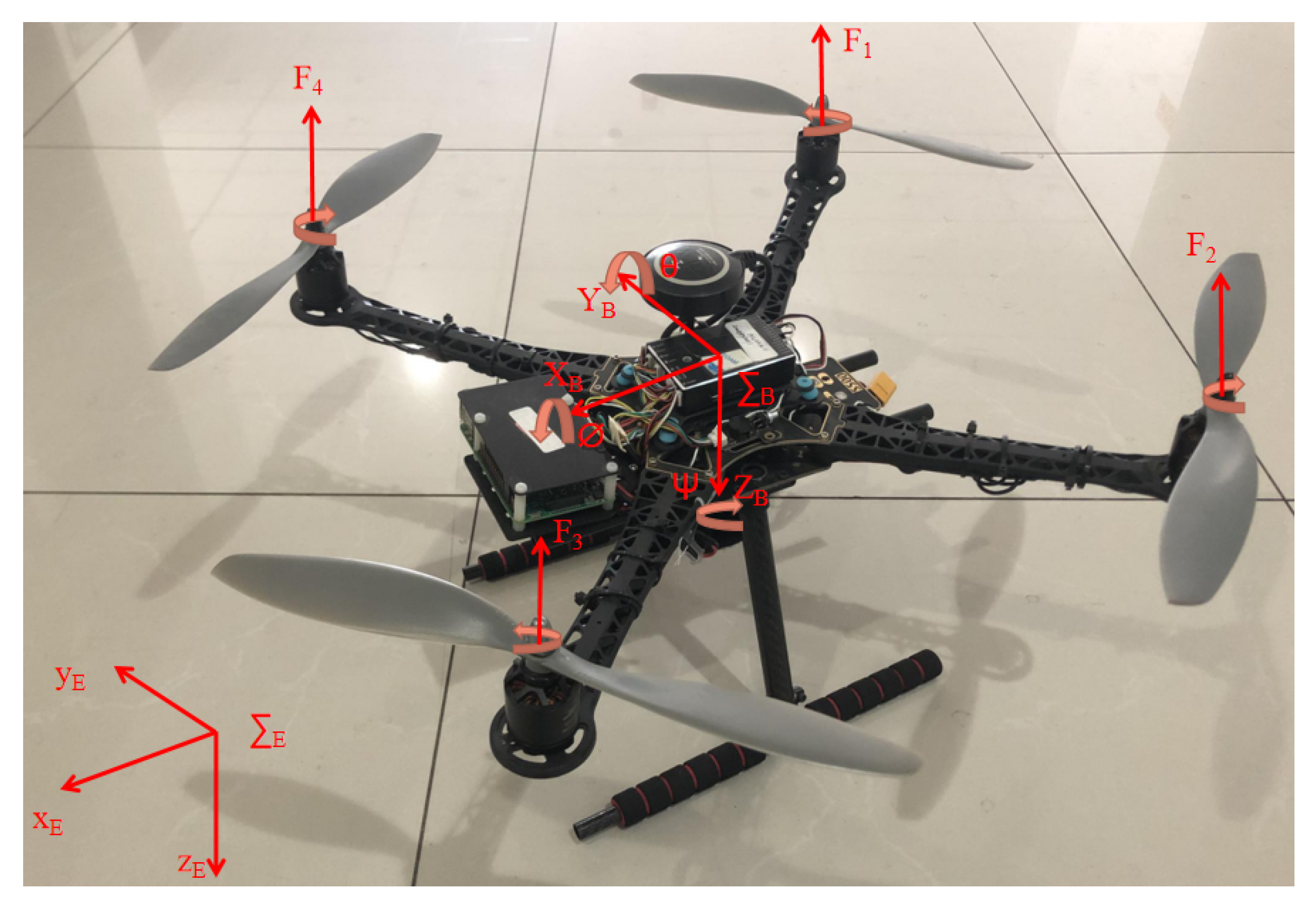
In this section, the dynamics model of the quadrotor UAV is constructed by the Newton-Euler method. The coordinate frames of the quadrotor UAV are defined as shown in Figure 1, where and denote the body coordinate frame and ground coordinate frame. The position of quadrotor with respect to is denoted by , and the attitude of quadrotor is denoted by the Euler angles , in which , , and , respectively, denote roll, pitch, and yaw angle. denotes the rotation matrix form to , which can be denoted as:
2.1. Thrust and Torque
Thrust and torque are two forces acting on the UAV, the thrust produces acceleration in three directions, and the torque produces rotation. The thrust produced by a single motor is proportional to the square of the motor speed, which can be defined as:
where is the thrust of single rotor, and is the thrust coefficient, is the speed of single motor. The total thrust generated by four motors is presented as:
is the total torque of quadrotor UAV, and it can be described with the following equations:
where , , and are the driving torques generated by the quadrotor UAV along the x-axis, z-axis, and z-axis with respect to B. is drag coefficient. l is the distance from the center of the motor to the origin of the body coordinate system. For convenience of control, we use independent control quantity , and it can be denoted as:
where is z-axis speed control input. is roll-axis control input. is pitch-axis control input. is yaw-axis control input.
There is also a kind of torque that produces by the gyroscopic effect which can be expressed as:
where , , , and is the total torque of inertia of rotors and motors.
Thus, the total torque can be writtened as:
where is the air resistance torque, and it can be expressed as:
where denotes the air resistance coefficient, and .
2.2. UAV Dynamic Model
Applying the Newton-Euler method, the quadrotor UAV dynamic model can be described with the following equations:
where m is the total mass of quadrotor UAV.
Because of the strong coupling in UAV, it is very difficult to design a model-based controller. Thus, we classify strong coupling relations as internal disturbances , and the attitude dynamics can be written as:
where:
The unknown disturbance mainly comes from the change of airflow, such as wind. In this paper, it is assumed that the total disturbance is bounded and will not lead to control saturation. The disturbance of wind is expressed as . The dynamic model with disturbance can be expressed as:
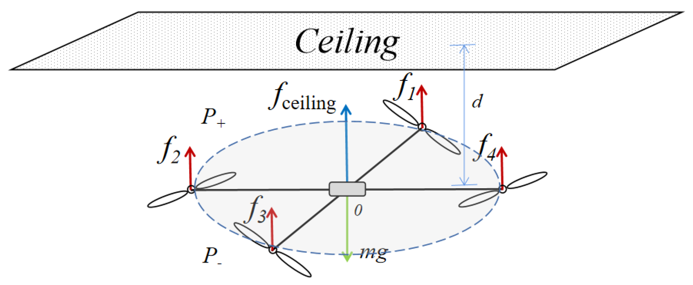
In addition to the effect of wind, there are also ground effect and ceiling effect in the external airflow disturbance. The ground effect exists in the process of UAV landing, which will produce a kind of resistance to UAV landing [41]. This paper focuses on the flight process of UAV, so the ceiling effect is worth considering. We assume that the ceiling effect occurs only in the z-axis direction [11].
As shown in Figure 2, d is the distance from the propeller plane to the ceiling. and are the pressures at the upper and lower parts of the propeller plane, respectively. The lift change generated by the ceiling effect of a single propeller can be expressed as
where is standard atmosphere. R is the radius of a rotor. is an efficient ratio . is the function of pressure and radial position r. At this time, the lift of UAV can be expressed as:
Define is the component of the force on the z-axis of the aircraft. Since the ceiling effect is assumed to affect only the z-axis, the dynamics of the z-axis can be written as
Because the control scheme in this paper is not based on the model, the lift change caused by will be estimated and compensated by the state observer as a disturbance term.
According to the dynamics model, the form of the transfer function for X-channel is the same as the form for Y-channel, while Roll-channel and Pitch-channel have the same form of the transfer function. According to the relevant data of quadrotor UAV, the parameters of quadrotor UAV is shown in Table 1.
Through the Laplacian transform, the transfer functions in quadrotor UAV are as follows:
(1) X-channel:
(2) Z-channel:
(3) Roll-channel:
(4) Yaw-channel:
3. Design of Fuzzy-LADRC
3.1. Control Scheme of Quadrotor UAV
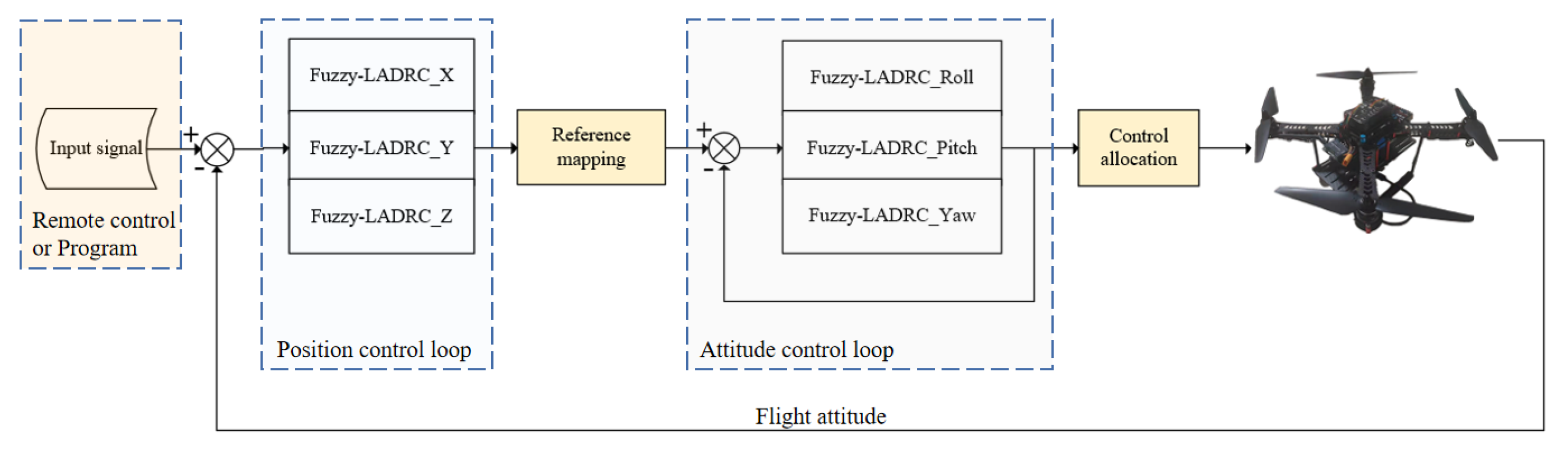
To test the UAV’s abilities of stability in control and anti-interference, we design a complete UAV control system based on the dynamics model. The quadrotor UAV uses four motors as power. By adjusting the speed of four motors, the force state of the UAV changes, which causes the change of the attitude and position. The position and attitude control system of the UAV is shown in Figure 3. This control system has two loops. The inner loop is attitude control, and the outer loop is position control.
3.2. The Principle of LADRC
LADRC is a linearization simplification of ADRC through deleting tracking differentiator (TD) and consists of linear extended state observer (LESO), linear state error feedback (LSEF), and error compensation control rate [36] with characteristics of high precision, fast response, and strong anti-interference ability [16]. LADRC regards internal disturbance and external unobserved disturbance as total disturbance of the system. The total disturbance can be observed by LESO, while compensating via the rate of linear control.
We choose a second order system as follows:
where a, b, c are system coefficients, is unknown disturbance, and u is input of the system.
By taking several items as total disturbance except the input, we have
where is total disturbance. Let be the LESO observed value of . The control rate is
If observed value of state observer is close to real disturbance value, then it can be described as
LADRC replaces PD controller by nonlinear states error feedback control laws (NLSEF), so we have
where and are the observed values of y and , and r is reference signal. and can be given as
where is the configured pole of the controller.
Assume the initial states of system are zeros and the Laplace form of (17) is
Equation (19) can be rewritten as:
That is:
In summary, LADRC can eliminate interference and track the input signal.
3.3. Design of Fuzzy-LADRC
The quadrotor UAV has six channels: X-channel; Y-channel; Z-channel; Roll-channel; Pitch-channel; Yaw-channel. Taking Roll-channel as an example, the Fuzzy-LADRC controller of the Roll-channel is introduced in detail, and other channels are constructed in the same way.
3.3.1. The Structure of Fuzzy-LADRC
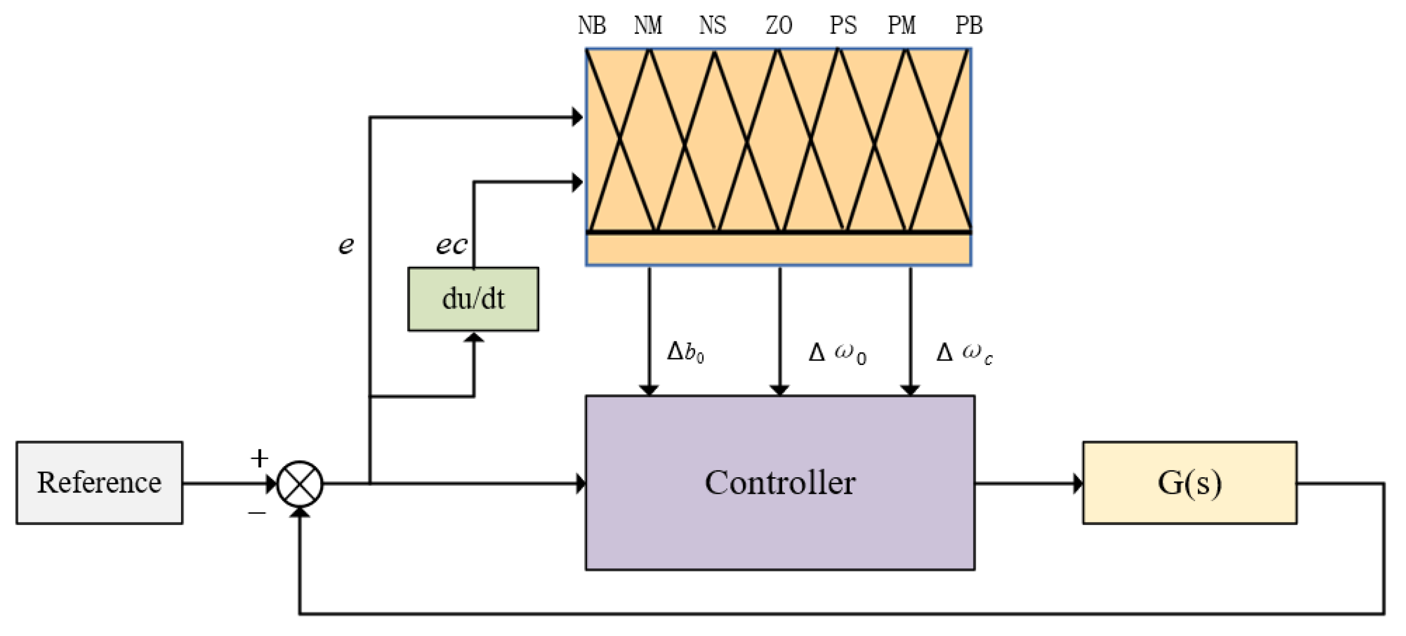
Fuzzy-LADRC is mainly composed of linear state error feedback (LSEF), fuzzy adaptive linear extended state observer (FLESO), and error compensation control (ECC). Among them, FLESO is the core module of Fuzzy-LADRC, in which its function is to observe and estimate disturbance. The structure of Fuzzy-LADRC is shown in Figure 4.
3.3.2. Design of Fuzzy Adaptive Controller
The input and output of fuzzy control are expressed as seven language values: negative big (NB); negative middle (NS); negative small (NS); zero (ZO); positive small (PS); positive middle (PM); positive big (PB). The parameters of Fuzzy-LADRC are , , and . and . is the bandwidth of controller, is the bandwidth of the observer, and is the compensation factor. When increases or decreases, the control ability enhances, and the system has a faster response, however, overshoot and oscillation will occur. With the increase of , LESO has a stronger ability to control the error, and the system responds faster, but the ability to observe noise also increases which leads to system shock. Firstly, the initialization parameters are set by experience, and then the PSO algorithm is used to get the optimal parameters. According to characteristics of these parameters, the fuzzy rules of , , and are shown in Table 2, Table 3 and Table 4.
The inputs of the fuzzy controller are the error e and the error change rate between the desired attitude and the current attitude. In this study, the triangle membership function with high sensitivity is used in the fuzzy process. According to the fuzzy rules, the weighted average method is adopted to obtain the modified values , , and . The parameters of Fuzzy-LADRC can be expressed as:
where , , and are the optimal initialization parameters calculated by PSO algorithm. The structure of fuzzy adaptive controller is shown in Figure 5.
3.3.3. Design of Fuzzy Linear Extended State Observer
The core of Fuzzy-LADRC is FLESO. FLESO can estimate unknown external disturbance of system and un-modeled internal disturbance in dynamics model. According to the dynamics model of Roll-channel, the state model of Roll-channel can be written as:
where , , and denotes , , and total disturbance.
The basic form of FLESO is as follows:
where is the estimate state of . is the gain of the observer, , , and . is the bandwidth of the observer.
According to (30) and (31), The FLESO in this paper can be expressed as:
3.3.4. Error Control Method
In Fuzzy-LADRC, the effect of FLEF is similar to that of PD controller. As can be seen from Figure 4, LSEF is expressed as:
where , are gains. Through the pole-placement to in control system, and .
The function of ECC is to eliminate the influence of disturbance through control rate. is a disturbance estimated by the extended state observer. As can be seen from Figure 4, ECC is expressed as:
3.4. Frequency Domain Stability Analysis
In this paper, the Roll-channel of the inner loop is taken as an example to prove the stability of the controller. For the outer loop position control, the stability proof process is similar.
When the UAV dynamic model is established, the internal coupling and external disturbance are unified as the total disturbance of the system. The dynamic model of the roll-channel can be further represented as follows:
where is total disturbance. is the measurable acceleration. Laplace transform is applied to (30)–(34), and the following expressions are obtained:
where is the actual value of roll angle. Substituting (36) into (37)
It is assumed that FLESO can accurately observe the total disturbance: . Use Laplace transform to (35)
The relationship between the roll angle output value and the actual value is obtained:
According to Routh criterion, it is proven that the sufficient and necessary condition for the closed-loop system to be stable is and . All the poles of the closed-loop system are located in the left half plane, and the system is BIBO stable. Since is the bandwidth of the controller, is a positive number. Therefore, the controller is stable.
4. Simulation and Discussion
Tracking the desired control signal and compensating for the unknown disturbance determine the operation quality of UAV. To investigate the dynamic response and robustness of Fuzzy-LADRC, this paper contrasts and analyzes Fuzzy-LADRC with LADRC, PID, and Fuzzy-PID, and four control systems are built in the Simulink of MATLAB R2019a. PSO algorithm is written in an M-file. The initialization parameters of each controller are given by experienced. Then, the PSO algorithm is used to optimize the parameters. The maximum number of iterations is 100, and the particle swarm size is 40. The evaluation function is to calculate the IAE of each system and take a group of parameters with the minimum IAE. The environment of the simulation experiments in this paper is a Core i7-9700F CPU, Windows 10 operating system, and a quad-core Intel processor. The physical memory is 16 GB, and the speed of the processor is 3.0 GHz. The obtained results show their respective control performance and anti-interference ability, respectively. The input signals and disturbance signals of the four controllers are the same. In this paper, the controller of each channel is simulated separately, and the signals of each control loop are independent. The comparative experimental structure of the four controllers is shown in Figure 6.
4.1. Tracking Experiment and Input Energy
Considering the actual flight process, it is necessary to accurately control the position and heading of the UAV. Therefore, in the tracking experiment, the desired position and attitude of the UAV will be used as the input signals of the controller. There are two kinds of reference signals: one is the step signal with a fixed amplitude of 0.5, and the other is the triangular wave signal which simulates the movement of UAV. In order to facilitate the analysis, the following performance indicators are used: is rise time; % is maximum overshoot; IAE is integral of the absolute value of error criterion. The experimental results of tracking step signal are shown in Figure 7, and the corresponding performance indicators are given in Figure 8 and Table 5.
According to Figure 7, the response speed of Fuzzy-LADRC is faster than LADRC, PID, and Fuzzy-PID. The IAE in Figure 8a shows the degree of deviation in the tracking process, and it is obvious that the IAE of Fuzzy-LADRC is the smallest. As can be seen from Figure 8b, there is no overshoot in both the X-channel and Z-channel of the Fuzzy-LADRC and LADRC. Although all controllers in Roll-channel and Yaw-channel have overshoot, the overshoot of Fuzzy-LADRC is minimal. According to Table 5, in X-channel and Z-channel, the rise time of Fuzzy-LADRC and LADRC is less than that of PID and Fuzzy-PID, and the rise time of Fuzzy-LADRC is the shortest. In the Roll-channel, the rise time of Fuzzy-LADRC is slightly higher than that of PID, but, as can be seen from Figure 8b, the overshoot of Fuzzy-LADRC is obviously less than that of PID. Therefore, Fuzzy-LADRC designed in this paper has the best performance in tracking the step signal.
The triangle wave signal is to simulate the real movement of the aircraft. In X-channel, the UAV moves forward and backward. In Z-channel, the UAV moves up and down. In Roll-channel, the UAV moves laterally. In Yaw-channel, the UAV nose rotates. The experimental results of tracking triangle wave signal are shown in Figure 9, and the corresponding IAE is shown in Figure 10.
It can be seen from Figure 9 that there are obvious errors in the tracking process of PID and Fuzzy-PID, and the speed of error elimination is slow. It can be seen from Figure 10 that the IAE of the proposed scheme is the smallest of the four control schemes. Therefore, the proposed control scheme is also effective for time-varying signals, such as triangular wave signal.
According to (34), is the control signal of the controller. Taking X-channel tracking triangle wave signal as an example, of the four controls are shown in Figure 11. For comparison purposes, the area of the region formed by and the time-axis is calculated as the input energy. The input energies of the four controllers are shown in Figure 12.
According to Figure 12, the proposed control scheme minimizes the input energy.
4.2. Disturbance Experiment
The disturbance of UAV is divided into internal and external, the internal disturbance is sensor noise, and the external disturbance includes wind, ceiling effect, and load change. In this study, the wind is used as an external disturbance to test the robustness of the system. As shown in Figure 13, two kinds of wind with different speeds and types are set as disturbance signals: (1) wind with fixed speed and direction (Figure 13a); and (2) time-varying wind with Gaussian white noise (Figure 13b).
Set the current state of UAV is hovering, and current location is , . At this time, the system is stable. Next, the disturbance is added, and the IAE of the system is measured as the performance evaluation index. The disturbance experiment results are shown in Figure 14 and Figure 15, as well as Table 6.
According to Figure 14 and Figure 15, it can be seen that Fuzzy-LADRC and LADRC have very strong compensation ability to disturbance, and the two kinds of disturbance signals have very small interference to the stable state of the system. However, the traditional PID control scheme is very sensitive to disturbance, which will cause a large overshoot to the system, and the system needs a long time to restore stability after being disturbed. According to Table 6, the IAE of Fuzzy-LADRC and LADEC is much smaller than that of PID. Therefore, the proposed control scheme has good disturbance compensation ability and robustness.
4.3. Robustness Experiment
In order to prove the robustness of the system with model parameter uncertainty, Monte Carlo experiments are carried out on the controller of the X-channel. All parameters of the dynamic model in the X-channel are perturbed by 20%. The input of the system is a unit step signal. The Fuzzy-LADRC and LADRC are tested 1000 times in Monte Carlo experiments. The settling time , rise time , and IAE of each experiment are calculated, respectively. The experimental results are shown in Figure 16.
The experimental results show that the scatterers of Fuzzy-LADRC are more concentrated and closer to the origin than those of LADRC. Therefore, the proposed scheme has good robustness.
5. Conclusions
In this paper, considering the disadvantages of traditional cascade PID, and the strong coupling and nonlinear of the UAV system, a novel LADRC method based on the fuzzy adaptive controller is proposed for the first time. The conclusion can be summarized as follows:
1. The dynamics model of UAV is established by the Newton-Euler method. The dynamics model established the relationship among position, attitude, and control variables. Based on that, LADRC is built, and the PSO algorithm is used to optimize the initialization parameters.
2. To solve the problem that the response speed of the traditional controller is slow, and the ability of anti-interference is weak, by considering the control effect of LADRC parameters on the system, we design a set of fuzzy rules according to our experience. Then, based on the fuzzy adaptive controller, the Fuzzy-LADRC is proposed.
3. Fuzzy-LADRC, LADRC, PID, and Fuzzy-PID are compared and analyzed. The simulation results show that the average response speed of Fuzzy-LADRC tracking control is 12.65% faster than LADRC and 29.25% faster than PID. Under the same disturbance, the average overshoot of Fuzzy-LADRC is 17% less than LADRC and 77.75% less than PID. The proposed control method can significantly improve response speed and anti-interference ability.
4. Based on the controller proposed in this paper, the ability of UAV to track control signal and compensate disturbance is improved significantly. The application level of UAV in industrial production fields will be greatly improved, which is conducive to industrial safety and economic benefits.
In future work, we will study the influence of ceiling effect and ground effect on UAV. To ensure the control ability of the UAV, the relationship between the strength of unknown disturbance and control saturation is studied by combining the performance of motor and the parameters of UAV. Finally, the control method proposed in this paper will be tested on the actual aircraft. At the same time, our study will attempt to use neural network technology and the reinforcement learning method to further improve the robustness of Fuzzy-LADRC.
Author Contributions
Conceptualization, C.S., M.L., and C.L.; data curation, C.S., C.L., and H.W.; formal analysis, C.S., M.L., H.W., and X.F.; funding acquisition, C.L., M.L., and H.W.; Investigation, C.S., M.L., and H.W.; Methodology, C.S., X.F., and H.W.; project administration, C.S., and H.W.; resources, C.S. and C.L.; software, C.S. and H.W.; supervision, C.L.; validation, C.S. and C.L.; visualization, C.S., M.L., H.W., and X.F.; writing—original draft, C.S., H.W., and X.F.; writing—review and editing, C.S., M.L., C.L., and X.F. All authors have read and agreed to the published version of the manuscript.
Funding
This research was funded by the Fundamental Research Funds for the Central Universities of China, grant number 2019QN045.
Acknowledgments
We would like to thank the Electric Intelligent Robot Research Center for providing equipments and platforms.
Conflicts of Interest
The authors declare no conflict of interest.
References
- Car, M.; Markovic, L.; Ivanovic, A.; Orsag, M.; Bogdan, S. Autonomous Wind-Turbine Blade Inspection Using LiDAR-Equipped Unmanned Aerial Vehicle. IEEE Access 2020, 8, 131380–131387. [Google Scholar] [CrossRef]
- Liu, Z.; Wang, X.; Liu, Y. Application of Unmanned Aerial Vehicle Hangar in Transmission Tower Inspection Considering the Risk Probabilities of Steel Towers. IEEE Access 2019, 7, 159048–159057. [Google Scholar] [CrossRef]
- Zhou, Z.; Zhang, C.; Xu, C.; Xiong, F.; Zhang, Y.; Umer, T. Energy-Efficient Industrial Internet of UAVs for Power Line Inspection in Smart Grid. IEEE Trans. Ind. Informatics 2018, 14, 2705–2714. [Google Scholar] [CrossRef] [Green Version]
- Gallardo-Saavedra, S.; Hernández-Callejo, L.; Duque-Perez, O. Image Resolution Influence in Aerial Thermographic Inspections of Photovoltaic Plants. IEEE Trans. Ind. Informatics 2018, 14, 5678–5686. [Google Scholar] [CrossRef]
- Kim, S.; Kim, D.; Jeong, S.; Ham, J.W.; Lee, J.K.; Oh, K.Y. Fault Diagnosis of Power Transmission Lines Using a UAV-Mounted Smart Inspection System. IEEE Access 2020, 8, 149999–150009. [Google Scholar] [CrossRef]
- Fang, S.; Haiyang, C.; Sheng, L.; Xiaoyu, W. A Framework of Power Pylon Detection for UAV-based Power Line Inspection. In Proceedings of the 2020 IEEE 5th Information Technology and Mechatronics Engineering Conference (ITOEC), Chongqing, China, 12–14 June 2020; pp. 350–357. [Google Scholar] [CrossRef]
- Zhang, J.; Liu, L.; Wang, B.; Chen, X.; Wang, Q.; Zheng, T. High Speed Automatic Power Line Detection and Tracking for a UAV-Based Inspection. In Proceedings of the 2012 International Conference on Industrial Control and Electronics Engineering, Xi’an, China, 23–25 August 2012; pp. 266–269. [Google Scholar] [CrossRef]
- Cao, P.; Liu, Y.; Yang, C.; Xie, S.; Xie, K. MEC-Driven UAV-Enabled Routine Inspection Scheme in Wind Farm Under Wind Influence. IEEE Access 2019, 7, 179252–179265. [Google Scholar] [CrossRef]
- Li, J.; Lei, G.; Xian, Y.; Wang, X. Research on Ground Effect of Shipborne Flying-Wing UAV. In Proceedings of the 2014 Tenth International Conference on Computational Intelligence and Security, Kunming, China, 15–16 November 2014; pp. 685–688. [Google Scholar] [CrossRef]
- Sanchez-Cuevas, P.; Heredia, G.; Ollero, A. Characterization of the Aerodynamic Ground Effect and Its Influence in Multirotor Control. Int. J. Aerosp. Eng. 2017, 2017, 1823056. [Google Scholar] [CrossRef]
- Kocer, B.B.; Tiryaki, M.E.; Pratama, M.; Tjahjowidodo, T.; Seet, G.G.L. Aerial Robot Control in Close Proximity to Ceiling: A Force Estimation-based Nonlinear MPC. In Proceedings of the 2019 IEEE/RSJ International Conference on Intelligent Robots and Systems (IROS), Macau, China, 3–8 November 2019; pp. 2813–2819. [Google Scholar] [CrossRef] [Green Version]
- Kocer, B.B.; Tjahjowidodo, T.; Seet, G.G.L. Centralized predictive ceiling interaction control of quadrotor VTOL UAV. Aerosp. Sci. Technol. 2018, 76, 455–465. [Google Scholar] [CrossRef]
- Sanchez-Cuevas, P.J.; Heredia, G.; Ollero, A. Multirotor UAS for bridge inspection by contact using the ceiling effect. In Proceedings of the 2017 International Conference on Unmanned Aircraft Systems (ICUAS), Miami, FL, USA, 13–16 June 2017; pp. 767–774. [Google Scholar] [CrossRef] [Green Version]
- Zhang, R.; Zhang, J.; Yu, H. Review of modeling and control in UAV autonomous maneuvering flight. In Proceedings of the 2018 IEEE International Conference on Mechatronics and Automation (ICMA), Changchun, China, 5–8 August 2018; pp. 1920–1925. [Google Scholar] [CrossRef]
- Poksawat, P.; Wang, L.; Mohamed, A. Gain Scheduled Attitude Control of Fixed-Wing UAV with Automatic Controller Tuning. IEEE Trans. Control Syst. Technol. 2018, 26, 1192–1203. [Google Scholar] [CrossRef]
- Vieira Lima, G.; Monteiro Jorge Alves de Souza, R.; Silva de Morais, A.; Oliveira-Lopes, L.C.; Mara Vieira Ladeira, G. Stabilization and Path Tracking of a Mini Quadrotor Helicopter: Experimental Results. IEEE Lat. Am. Trans. 2019, 17, 485–492. [Google Scholar] [CrossRef]
- Noordin, A.; Basri, M.A.M.; Mohamed, Z.; Lazim, I.M. Adaptive PID Controller Using Sliding Mode Control Approaches for Quadrotor UAV Attitude and Position Stabilization. Arab. J. Sci. Eng. 2020. [Google Scholar] [CrossRef]
- Rosales, C.; Tosetti, S.; Soria, C.; Rossomando, F. Neural Adaptive PID Control of a Quadrotor using EFK. IEEE Lat. Am. Trans. 2018, 16, 2722–2730. [Google Scholar] [CrossRef]
- Zhu, Z.; Cao, S. Back-stepping sliding mode control method for quadrotor UAV with actuator failure. J. Eng. 2019, 2019, 8374–8377. [Google Scholar] [CrossRef]
- Wang, Z.; Wang, Q.; Dong, C. Asynchronous H∞ control for unmanned aerial vehicles: Switched polytopic system approach. IEEE/CAA J. Autom. Sin. 2015, 2, 207–216. [Google Scholar] [CrossRef]
- Al Younes, Y.; Drak, A.; Noura, H.; Rabhi, A.; El Hajjaji, A. Robust Model-Free Control Applied to a Quadrotor UAV. J. Intell. Robot. Syst. 2016, 84, 37–52. [Google Scholar] [CrossRef]
- Xu, Q.; Wang, Z.; Zhen, Z. Adaptive neural network finite time control for quadrotor UAV with unknown input saturation. Nonlinear Dyn. 2019, 98, 1973–1998. [Google Scholar] [CrossRef]
- Lopez, B.T.; Slotine, J.E.; How, J.P. Dynamic Tube MPC for Nonlinear Systems. In Proceedings of the 2019 American Control Conference (ACC), Philadelphia, PA, USA, 10–12 July 2019; pp. 1655–1662. [Google Scholar] [CrossRef] [Green Version]
- Feng, S.; Sun, H.; Zhang, Y.; Zheng, J.; Liu, H.X.; Li, L. Tube-Based Discrete Controller Design for Vehicle Platoons Subject to Disturbances and Saturation Constraints. IEEE Trans. Control Syst. Technol. 2020, 28, 1066–1073. [Google Scholar] [CrossRef]
- Mayne, D. Robust and stochastic model predictive control: Are we going in the right direction? Annu. Rev. Control 2016, 41, 184–192. [Google Scholar] [CrossRef]
- Peng-ya, X.; Yun-jie, W.; Jing-xing, Z.; Ling, C. Longitudinal attitude control of UAV based on fuzzy PID. In Proceedings of the 2018 IEEE CSAA Guidance, Navigation and Control Conference (CGNCC), Xiamen, China, 10–12 August 2018; pp. 1–5. [Google Scholar] [CrossRef]
- Zhang, X.; Lin, H. Backstepping Fuzzy Sliding Mode Control for the Antiskid Braking System of Unmanned Aerial Vehicles. Electronics 2020, 9, 1731. [Google Scholar] [CrossRef]
- Li, K.; Wei, Y.; Wang, C.; Deng, H. Longitudinal Attitude Control Decoupling Algorithm Based on the Fuzzy Sliding Mode of a Coaxial-Rotor UAV. Electronics 2019, 8, 107. [Google Scholar] [CrossRef] [Green Version]
- Han, J. Active Disturbance Rejection Control Technology; National Defense Industry Press: Beijing, China, 2008. [Google Scholar]
- Wang, J.; Wang, X.; Luo, Z.; Assadian, F. Active disturbance rejection control of differential drive assist steering for electric vehicles. Energies 2020, 13, 2647. [Google Scholar] [CrossRef]
- Humaidi, A.J.; Ibraheem, I.K. Speed control of permanent magnet dC motor with friction and measurement noise using novel nonlinear extended state observer-based anti-disturbance control. Energies 2019, 12, 1651. [Google Scholar] [CrossRef] [Green Version]
- Zhang, Y.; Chen, Z.; Zhang, X.; Sun, Q.; Sun, M. A novel control scheme for quadrotor UAV based upon active disturbance rejection control. Aerosp. Ence Technol. 2018, 79, 601–609. [Google Scholar] [CrossRef]
- Lotufo, M.A.; Colangelo, L.; Perez-Montenegro, C.; Canuto, E.; Novara, C. UAV quadrotor attitude control: An ADRC-EMC combined approach. Control Eng. Pract. 2019, 84, 13–22. [Google Scholar] [CrossRef]
- Zhang, Y.; Chen, Z.; Sun, M. Trajectory tracking control for a quadrotor unmanned aerial vehicle based on dynamic surface active disturbance rejection control. Trans. Inst. Meas. Control 2020. [Google Scholar] [CrossRef]
- Niu, T.; Xiong, H.; Zhao, S. Based on ADRC UAV longitudinal pitching Angle control research. In Proceedings of the 2016 IEEE Information Technology, Networking, Electronic and Automation Control Conference, Chongqing, China, 20–22 May 2016; pp. 21–25. [Google Scholar] [CrossRef]
- Gao, Z. Scaling and bandwidth-parameterization based controller tuning. In Proceedings of the 2003 American Control Conference, Denver, CO, USA, 4–6 June 2003; Volume 6, pp. 4989–4996. [Google Scholar] [CrossRef]
- Zhou, X.; Wang, C.; Ma, Y. Vector speed regulation of an asynchronous motor based on improved first-order linear active disturbance rejection technology. Energies 2020, 13, 2168. [Google Scholar] [CrossRef]
- Li, H.; Li, S.; Lu, J.; Qu, Y.; Guo, C. A Novel Strategy Based on Linear Active Disturbance Rejection Control for Harmonic Detection and Compensation in Low Voltage AC Microgrid. Energies 2019, 12, 3982. [Google Scholar] [CrossRef] [Green Version]
- Wu, J.; Wang, H.; Su, Z.; Shao, X. UAV broken-line path following under disturbance conditions. J. Aerosp. Eng. 2018, 31. [Google Scholar] [CrossRef]
- Liang, X.; Li, J.; Zhao, F. Attitude Control of Quadrotor UAV Based on LADRC Method. In Proceedings of the 2019 Chinese Control And Decision Conference (CCDC), Nanchang, China, 3–5 June 2019; pp. 1924–1929. [Google Scholar] [CrossRef]
- Liu, H.; Zhao, W.; Zuo, Z.; Zhong, Y. Robust Control for Quadrotors with Multiple Time-Varying Uncertainties and Delays. IEEE Trans. Ind. Electron. 2017, 64, 1303–1312. [Google Scholar] [CrossRef]
Figure 1.
Structure and coordinate system of quadrotor unmanned aerial vehicle (UAV).

Figure 2.
Influence of ceiling effect on quadrotor UAV.

Figure 3.
The control of UAV is a cascade feedback control system. The outer loop is position control, and the inner loop is attitude control.
Figure 3.
The control of UAV is a cascade feedback control system. The outer loop is position control, and the inner loop is attitude control.

Figure 4.
The structure and components of fuzzy adaptive linear active disturbance rejection control (Fuzzy-LADRC).
Figure 4.
The structure and components of fuzzy adaptive linear active disturbance rejection control (Fuzzy-LADRC).

Figure 5.
The structure of fuzzy adaptive controller.

Figure 6.
The structure of comparative experiment of four controllers.

Figure 7.
The results of tracking step signal.

Figure 8.
Comparison of IAE and % of four controllers in tracking step signal experiment.

Figure 9.
The results of tracking triangle wave signal.

Figure 10.
IAE for tracking triangle wave signal.

Figure 11.
Controller inputs of X-channel when tracking triangle wave signal.

Figure 12.
The input energies of .

Figure 13.
Two different types of disturbance signals.

Figure 14.
Experimental results of disturbance (1).

Figure 15.
Experimental results of disturbance (2).

Figure 16.
Monte Carlo experimental results.


Table 1.
The parameters of quadrotor UAV.
| Parameter | Unit | Value |
|---|---|---|
| m | kg | 1.5 |
| l | m | 0.4 |
| Ns | ||
| Nms | ||
| Kgm | ||
| Kgm | ||
| Kgm |
Table 2.
Fuzzy rules for .
| NB | NM | NS | ZO | PS | PM | PB | ||
|---|---|---|---|---|---|---|---|---|
| e | NB | NB | NB | NM | NM | NS | ZO | ZO |
| NM | NB | NB | NM | NM | NS | ZO | ZO | |
| NS | NM | NM | NS | NS | ZO | ZO | PS | |
| ZO | NM | NS | NS | ZO | PS | PS | PM | |
| PS | NS | NS | ZO | PS | PM | PM | PB | |
| PM | ZO | ZO | PS | PM | PM | PB | PB | |
| PB | ZO | PS | PM | PM | PB | PB | PB | |
Table 3.
Fuzzy rules for .
| NB | NM | NS | ZO | PS | PM | PB | ||
|---|---|---|---|---|---|---|---|---|
| e | NB | PB | PB | PM | PM | PS | ZO | ZO |
| NM | PB | PB | PM | PM | PS | ZO | ZO | |
| NS | PM | PM | PS | PS | PS | PS | NS | |
| ZO | PM | PS | PS | NB | NB | NB | NS | |
| PS | NS | NS | NS | NS | NS | NM | NM | |
| PM | PM | PM | PB | PB | PB | PB | PB | |
| PB | PB | PB | PB | PB | PB | PB | PB | |
Table 4.
Fuzzy rules for .
| NB | NM | NS | ZO | PS | PM | PB | ||
|---|---|---|---|---|---|---|---|---|
| e | NB | PB | PB | PM | PM | PS | ZO | ZO |
| NM | PB | PB | PM | PM | PS | ZO | ZO | |
| NS | PM | PM | PS | PS | ZO | ZO | NS | |
| ZO | PM | PS | PS | ZO | NS | NS | NM | |
| PS | PS | ZO | ZO | NS | NM | NM | NM | |
| PM | ZO | ZO | NS | NM | NM | NB | NB | |
| PB | ZO | NS | NM | NM | NB | NB | NB | |
Table 5.
Rise time (ms) of tracking step signal.
| Channel | Fuzzy-LADRC | LADRC | PID | Fuzzy-PID |
|---|---|---|---|---|
| X | 240.806 | 283.164 | 443.399 | 458.699 |
| Z | 446.113 | 655.948 | 1050.423 | 938.950 |
| Roll | 43.824 | 45.014 | 40.839 | 33.953 |
| Yaw | 35.896 | 36.128 | 45.169 | 32.990 |
Table 6.
Disturbance experiment results under two kinds of disturbance signals.
| IAE | Disturbance (1) | Disturbance (2) | ||||||
|---|---|---|---|---|---|---|---|---|
| X | Z | Roll | Yaw | X | Z | Roll | Yaw | |
| Fuzzy-LADRC | 0.4507 | 0.0798 | 0.4229 | 0.7435 | 7.2666 | 1.0446 | 11.7110 | 12.7429 |
| LADRC | 0.5901 | 0.0827 | 0.4908 | 0.9297 | 9.4654 | 1.1963 | 12.4671 | 14.0729 |
| PID | 128.1835 | 274.6368 | 34.1867 | 11.6689 | 1373.3657 | 1695.544 | 480.7782 | 57.9432 |
Publisher’s Note: MDPI stays neutral with regard to jurisdictional claims in published maps and institutional affiliations. |
© 2021 by the authors. Licensee MDPI, Basel, Switzerland. This article is an open access article distributed under the terms and conditions of the Creative Commons Attribution (CC BY) license (http://creativecommons.org/licenses/by/4.0/).
Share and Cite
MDPI and ACS Style
Sun, C.; Liu, M.; Liu, C.; Feng, X.; Wu, H. An Industrial Quadrotor UAV Control Method Based on Fuzzy Adaptive Linear Active Disturbance Rejection Control. Electronics 2021, 10, 376. https://doi.org/10.3390/electronics10040376
AMA Style
Sun C, Liu M, Liu C, Feng X, Wu H. An Industrial Quadrotor UAV Control Method Based on Fuzzy Adaptive Linear Active Disturbance Rejection Control. Electronics. 2021; 10(4):376. https://doi.org/10.3390/electronics10040376
Chicago/Turabian StyleSun, Changhao, Mengqi Liu, Chang’an Liu, Xueling Feng, and Hua Wu. 2021. "An Industrial Quadrotor UAV Control Method Based on Fuzzy Adaptive Linear Active Disturbance Rejection Control" Electronics 10, no. 4: 376. https://doi.org/10.3390/electronics10040376
Note that from the first issue of 2016, this journal uses article numbers instead of page numbers. See further details here.