
A New Hybrid Prime Code for OCDMA Network Multimedia Applications


1
Electrical Engineering Department, Shaqra University, Ar. Riyadh 11911, Saudi Arabia
2
Electronics and Communications Engineering, College of Engineering and Technology, Arab Academy for Science, Technology and Maritime Transport, Alexandria 1029, Egypt
*
Author to whom correspondence should be addressed.
Electronics 2021, 10(21), 2705; https://doi.org/10.3390/electronics10212705
Submission received: 17 October 2021
/
Revised: 3 November 2021
/
Accepted: 4 November 2021
/
Published: 5 November 2021
(This article belongs to the Collection Application of Advanced Computing, Control and Processing in Engineering)
Abstract
:This paper presents a new family of spreading code sequences called hybrid prime code (HPC), to be used as source code for the optical code division multiple access (OCDMA) network for large network capacity. The network capacity directly depends on the number of available code sequences provided and their correlation properties. Therefore, the proposed HPC is designed based on combining two or more different code words belonging to two or more different prime numbers. This increases the number of code sequences generated. The code construction method utilized allows the generation of different code sets, each with different code length and weight, according to the number of prime numbers used. In addition, the incoherent pulse position modulation (PPM) OCDMA system is proposed based on the HPC code. Furthermore, the bit error rate (BER) performance analysis is introduced versus the received optical power and the number of active users. Moreover, the error vector magnitude (EVM) is calculated versus the optical signal-to-noise ratio. This work proves that using two prime numbers simultaneously generates far more codes than using prime numbers separately. It also achieved an OCDMA system capacity higher than the system that uses the optical orthogonal codes (OOCs), modified prime codes (MPCs) families, and two code families with separate simultaneously prime numbers, at a BER below 10−9 which is the optimum level.
1. Introduction
In the last three decades, there were two main categories of optical orthogonal codes, based on (0, 1) logic, and were introduced into the optical code division multiple access (OCDMA) networks. The first code category refers to the optical orthogonal codes (OOCs) and is designed with low off-peak, auto- and cross-correlation properties for the purposes of frame synchronization and minimum interference [1,2,3,4,5,6,7,8,9]. The second one refers to the prime codes (PCs) and is designed to sacrifice the auto-correlation property [10,11,12,13,14,15,16,17,18,19,20,21]. In direct sequence OCDMA (DS-OCDMA) networks, each user assigns a different code sequence to spread its data bits. Moreover, all code sequences are orthogonal and share the same available bandwidth such as the OOCs, MPCs, and other spreading codes in the literatures. Before the spreading, line coding such as block codes can be used at the bit level in order to detect and correct the data bits at the receiving end.
In order to improve the OCDMA network’s performance, many researchers have focused on the modification of the OOC and PC parameters such as code length, code weight, and code correlation properties. Ultimately, the total number of code sequences provided is the most important network parameter. It limits the number of users sharing the network simultaneously. To date, all of the previous results demonstrated that the PC family such as; modified PCs (MPCs), padded MPCs (PMPC), new-MPCs (n-MPC), double padded MPCs (DPMPCs), uniform cross-correlation MPCs (UC-MPCs), enhanced MPCs (EMPCs), and weighted MPCs (WMPCs) can offer a greater number of sequences with much better characteristics than the OOC [22,23,24,25,26].
Within the PC family, the WMPC is an improvement over MPC, i.e., double the number of code sequences, higher code weight, and better correlation properties assuming the same PC sequence length [27,28,29,30,31,32,33]. The MPC uses complex analysis methods to increase the code weight to further comply with the auto-correlation peak value. From these observations, the main objective of this study is to propose a new code family called hybrid prime codes (HPC) that is not related to the MPC and their method of construction but only depends on the code words of the PC. This new code family is able to provide data for the following issues efficiently:
- (1)
- Maximum number of code sequences for maximum number of users, leading to an increase in the network capacity for data and multimedia applications.
- (2)
- Minimum code length to increase the user bit rate.
- (3)
- Optimal code weight for good network bit error rate (BER) performance.
- (4)
- Minimum cross-correlation values to prevent multiple access interference (MAI).
- (5)
- Reliable code parameter variation while keeping the same cross-correlation value.
- (6)
- Simplicity of code generation.
- (7)
- Minimum cost with respect to the line coding techniques in optical domain.
Two main goals required for a high performance OCDMA network:
- (1)
- High signal integrity in the midst of interference at the receiving end.
- (2)
- Broader network capacity.
Therefore, all optical code sequences have to be in the optical orthogonal category in order to distinguish the target user from the rest.
The remainder of this paper is organized as follows. Section 2 is a literature review on the 2-D OCDMA codes. The construction principles and correlation properties of the HPC are introduced in Section 3. Section 4 shows the code correlation results. The proposed OCDMA system model is illustrated in Section 5. Section 6 is the BER performance analysis, while Section 7 is the throughput analysis. Section 8 displays and discusses the simulation results. Section 10 is devoted to the main conclusions.
2. Literature Review
The main disadvantage of the 1D code is the need for a long code length for a large system capacity, where a large bandwidth is used in spectral coding and ultrashort pulses have to be used in temporal coding. Various 2D schemes are proposed to circumvent this problem. The 2D code can be constructed through various combinations of time, spectral, and space. There has been much research into the 2D spectral/time, spectral/space, and space/time domains. One of the most popular schemes is the MPC. In this scheme, different data bits are temporally spread by using optical delay lines for the incoherent OCDMA networks. In this section, we will present the most important previous research, as well as what has been accomplished in each research. This will lead us to present the idea and importance of the proposed code.
In [34], the design of a 2D temporal/spatial incoherent OCDMA system is presented based on matrix codes with experimental results. The proposed system BRE performance was compared with the performance of the other system which uses the temporal codes. The results showed that the system performance based on the proposed designed code is better than the systems that use other codes. This is due to the lower losses with no side lobes in auto-correlation property.
In [35], the authors proposed a new set of 2D wavelength/time codes with orthogonal properties in both domains for the OCDMA network. This code set was generated by an array of fiber gratings and was constructed based on the expansion operation from the 1D to 2D Hamming correlation. The BER performance was derived theoretically in terms of only the MAI and all other noise sources are neglected. The numerical simulations proved that the BER was improved compared with the BER of the systems that use other codes when using the smallest number of wavelength sets.
In [36], the generation of a 2D pseudo-orthogonal code sequence was presented using the optimum Golomb rules. The authors analyzed the BER performance of a synchronous OCDMA system using 2D wavelength/time codes. It was shown that this code has higher cardinality and good spectral density than the linear code sequence.
In [37], the spatial/spectral codes and corresponding system architecture were presented. The developed code was constructed based on two 1D M-sequences. The detection operation at the receiver was performed using only a binary multiplier. The authors proved that these codes have better BER performance than 1D M-sequence code if the number of active users is increased in the network. However, the MAI limits the system performance because of the dependency on the 1D M-sequence for the code construction.
In [38], a new code family named 2D projection code was proposed with a balanced detection receiver. The code construction was based on the projection of 2D code into 1D wavelength code. The MAI was eliminated using the balanced detector. The BER performance was improved at the higher number of active users compared with the differential detection techniques.
In [39], a 2D wavelength/time OOCs family was constructed for asynchronous OCDMA systems. These codes have more flexibility than the conventional 2D codes relative to the code size. The system performance based on the Markov chain technique was analyzed. The authors proved that this code provides better BER performance than the others, and the number of active users is dependent on the code size.
In [40], the authors developed a 2D spatial/spectral code and used a MAI cancellation technique to enhance the BER performance. This code family was constructed based on a 1D perfect difference code and was named 2D perfect difference code. Moreover, the transceiver architecture was presented based on this 2D code and the results indicated that this system can accommodate more active users than the 2D M-sequence codes.
In [41], the authors combined one-coincidence frequency hop code (OCFHC) and OOC to demonstrate a new code called OCFHC/OOC. In this code, each code word used a single wavelength. The maximum cross-correlation between any pair of code words is one. The authors evaluated the system performance in terms of the throughput based on a new method called effective normalized throughput with the diverse code method used as a benchmark. Moreover, the numerical simulations of the BER performance are presented.
In [42], the authors constructed a high parameter-flexible 2D minimum weight OOC. They used minimum wavelengths that corresponded to the code weight with short lengths. Moreover, the electrical coding/decoding process was investigated based on the parallel interference cancellation receiver. The authors proved that when the encoder and decoder were implemented, electrically, the parallel interference cancellation receiver worked better than the conventional correlation receiver.
In [43], a 2D spectral/spatial code was developed based on the existing modified quadratic congruence code and M-sequence code. The authors used a tunable fiber Bragg grating to construct the corresponding transceiver. The receiver was designed to eliminate the MAI and enhance the system BER performance.
In [44], a new spectral/spatial code called diluted perfect difference code was developed. The code construction was based on the dilution method and the 1D perfect difference code. The corresponding OCDMA transceiver was presented. This code has a MAI cancellation property used to eliminate the interference between users due to multiple access. The authors proved that the BER performance, when calculated using the proposed code, is better than the other codes at 1.5 Gbps and 2.5 Gbps.
In [45,46], a new 2D wavelength/time code family was proposed based on the modified quadratic congruence code. The encoder/decoder structures were presented based on tunable optical delay lines. The balanced detector was used at the receiver to completely eliminate the MAI. It was proven that the OCDMA system using this new code can accommodate a larger number of active users with a better BER performance than the system using 2D wavelength/spatial M-matrix code.
In [22], a 2D weighted modified prime code (WMPC) based on the existing MPC was developed. The author analyzed and presented the auto-correlation and cross-correlation properties of this new code in comparison with all the codes belonging to the MPC. The obtained results proved that the cross-correlation property of this code is limited to one and the auto-correlation property is higher than that of other MPC families. In [47], the design of 2D photonic crystal OCDMA encoder based on the WMPC was developed and presented.
In [48,49], a 2D multi-length WMPC (ML-WMPC), in multi-rate form based on multiple prime numbers, was used to accommodate different rates of multimedia services in the incoherent PPM-OCDMA network. In this research, the system BER performance was analyzed for different OCDMA receivers and the MAI cancellation receiver with Manchester encoding achieved better performance. The authors proved that the BER performance of network based on this multi-length code outperforms the ML-OOC’s and all MPC families in the presence of the MAI cancellation receiver and Manchester encoding.
In [50,51], a new 2D double-length MPC (DL-MPC) was applied to wireless incoherent PPM-OCDMA and coherent BPSK-OCDMA networks, respectively. The wireless channel model was represented by a gamma–gamma model. In [51], the balanced detector was used at the receiving end to completely eliminate the MAI and other noise. The authors proved that the BER performance of coherent BPSK-OCDMA systems based on a new code outperforms all the incoherent and coherent systems using the other codes.
In [52,53], a 2D optimized MPC (OMPC) was developed to improve the BER performance of the PPM-OCDMA system by increasing the code weight of the DL-MPC to an optimum value. The MAI cancellation receiver was used to improve the signal-to-noise ratio. The code characteristics are compared with the other existing code characteristics and the proposed OMPC proved to be the best. Furthermore, the system BER performance based on this code was improved compared with the other existing codes.
3. Code Construction
The proposed HPC code is based on using two different prime numbers P1 and P2; P2 is the greater prime number than P1. Each prime number can generate a number of code words equal to the same prime number. Each code word contains a number of chips equal to the corresponding prime number. Each code word contains one active chip “HIGH” and the remaining chips are “ZEROs”. The position of the active chip is , where . For the first prime number i, the code words can be generated as and for the second prime number Pj, the code words can be generated as . For example, when P1 = 5 and P2 = 7, the generated code words are listed in the following two groups:
The code words listed in the above two groups are then utilized to construct the two code sequence trees as shown in Table 1 and Table 2 based on the branching operation.
The number of code sequences in the first and second trees in Table 1 and Table 2 are and respectively. However, it is also shown in the two-code sequence trees that . Thus, the number after the minus sign, such as 1, represents the number of code sequences that are not used in coding construction (the bold faced and highlighted code sequences in Table 2).
3.1. Code Construction Procedure
- (a)
- Arrange the code sequences in the first tree, row by row in one column, as shown in Table 3, column 1.
- (b)
- (c)
- Rotate the final code sequences in column 2 horizontally from right to left until the first code word in this sequence becomes the last one, as shown in Table 3, column 3.
After these operations, the final code sequence can generally be expressed as:
The total number of code sequences in Table 3 is equal to K, where (i.e., equals four in column 2, Table 3) and the total number of code sequences can be generated equal to 2 K if the left half code sequences (the folded tree) in Table 2 have been used.

Table 3.
HPC sequences for P1 = 5 and P2 = 7.
| Column 1 | Column 2 | Column 3 | |||
|---|---|---|---|---|---|
| Code Index m | First Tree Code Sequences | Merged Code Sequences | Resultant Code Sequences | ||
| 0 | C0 | C00 | = 100001000000010000100000 | ||
| C01 | = 010000010000100000001000 | ||||
| C02 | = 010000100000100001000000 | ||||
| C03 | = 100000001000010000010000 | ||||
| 1 | C1 | C10 | = 100000100000001000010000 | ||
| C11 | = 001000010000010000000100 | ||||
| C12 | = 001000010000100000100000 | ||||
| C13 | = 010000000100001000010000 | ||||
| 2 | C2 | C20 | = 100000010000000100001000 | ||
| C21 | = 000100010000001000000010 | ||||
| C22 | = 000100001000100000010000 | ||||
| C23 | = 001000000010000100010000 | ||||
| 3 | C3 | C30 | = 100000001000000010000100 | ||
| C31 | = 000010010000000100000001 | ||||
| C32 | = 000010000100100000001000 | ||||
| C33 | = 000100000001000010010000 | ||||
| 4 | C4 | C40 | = 010000000100001000000010 | ||
| C41 | = 000001001000000010000100 | ||||
| C42 | = 001000000010010000000100 | ||||
| C43 | = 000010000100000001001000 | ||||
| 5 | C5 | C50 | = 010000000010000100000001 | ||
| C51 | = 000000101000000001000010 | ||||
| C52 | = 000100000001010000000010 | ||||
| C53 | = 000001000010000000101000 | ||||
| 6 | C6 | C60 | = 010001000000000010010000 | ||
| C61 | = 001000001000100000000001 | ||||
| C62 | = 000010010000010001000000 | ||||
| C63 | = 100000000001001000001000 | ||||
| 7 | C7 | C70 | = 001000100000000100001000 | ||
| C71 | = 000100000100010000000010 | ||||
| C72 | = 000100001000001000100000 | ||||
| C73 | = 010000000010000100000100 | ||||
| 8 | C8 | C80 | = 001000010000000010000100 | ||
| C81 | = 000010000100001000000001 | ||||
| C82 | = 000010000100001000010000 | ||||
| C83 | = 001000000001000010000100 | ||||
| 9 | C9 | C90 | = 000100001000000010000010 | ||
| C91 | = 000001000010000100000001 | ||||
| C92 | = 000010000010000100001000 | ||||
| C93 | = 000100000001000001000010 | ||||
| 10 | C10 | C100 | = 010000000100100000000001 | ||
| C101 | = 000000101000000010010000 | ||||
| C102 | = 100000000001010000000100 | ||||
| C103 | = 000010010000000000101000 | ||||
| 11 | C11 | C110 | = 001001000000100000001000 | ||
| C111 | = 000100000100100000010000 | ||||
| C112 | = 100000001000001001000000 | ||||
| C113 | = 100000010000000100000100 | ||||
| 12 | C12 | C120 | = 000100100000100000000100 | ||
| C121 | = 000010000010010000010000 | ||||
| C122 | = 100000000100000100100000 | ||||
| C123 | = 010000010000000010000010 | ||||
| 13 | C13 | C130 | = 000010010000100000000010 | ||
| C131 | = 000001000001001000010000 | ||||
| C132 | = 100000000010000010010000 | ||||
| C133 | = 001000010000000001000001 | ||||
| 14 | C14 | C140 | = 001000001000010000000001 | ||
| C141 | = 000000100100000100001000 | ||||
| C142 | = 010000000001001000001000 | ||||
| C143 | = 000100001000000000100100 | ||||
| 15 | C15 | C150 | = 000101000000010000000100 | ||
| C151 | = 000010000010100000001000 | ||||
| C152 | = 010000000100000101000000 | ||||
| C153 | = 100000001000000010000010 | ||||
| 16 | C16 | C160 | = 000010100000010000000010 | ||
| C161 | = 000001000001010000001000 | ||||
| C162 | = 010000000010000010100000 | ||||
| C163 | = 010000001000000001000001 | ||||
| 17 | C17 | C170 | = 000100010000001000000001 | ||
| C171 | = 000000100010001000000100 | ||||
| C172 | = 001000000001000100010000 | ||||
| C173 | = 001000000100000000100010 | ||||
| 18 | C18 | C180 | = 000011000000001000000010 | ||
| C181 | = 000001000001100000000100 | ||||
| C182 | = 001000000010000011000000 | ||||
| C183 | = 100000000100000001000001 | ||||
| 19 | C19 | C190 | = 000010100000000100000001 | ||
| C191 | = 000000100001010000000010 | ||||
| C192 | = 000100000001000010100000 | ||||
| C193 | = 010000000010000000100001 | ||||
In comparison with the other orthogonal codes used in the OCDMA networks, such as the OOCs and the MPCs, the proposed code achieved the following advantages:
- Limited cross-correlation “0” or “1”;
- Very large number of code sequences can provide a large number of simultaneous users without sacrificing performance;
- Shorter code length for the same higher bit rate transmission.
Table 4 summarizes the comparison between the HPC and the other orthogonal codes used in the OCDMA networks.
Table 4 shows that the number of sequences provided by the OOC, MPC, and HPC are 2, 25, and 160, respectively. Moreover, the code lengths of the OOC, MPC, and HPC are 32, 25, and 24, respectively when P2 = 7.
3.2. Correlation Properties
Equation (1) represents the auto- and cross-correlation functions of the HPC sequences according to Table 3.
This equation illustrates that:
- (a)
- The peak value of the auto-correlation property is 2n, where n is an integer number equal to the number of code words used to construct the code sequence in each tree.
- (b)
- The value of the cross-correlation property is “0” or “1” between any two different code sequences in the coding of Table 3 and is independent of whether these two codes share the same code index or not.
- (c)
- and
4. Correlation Results
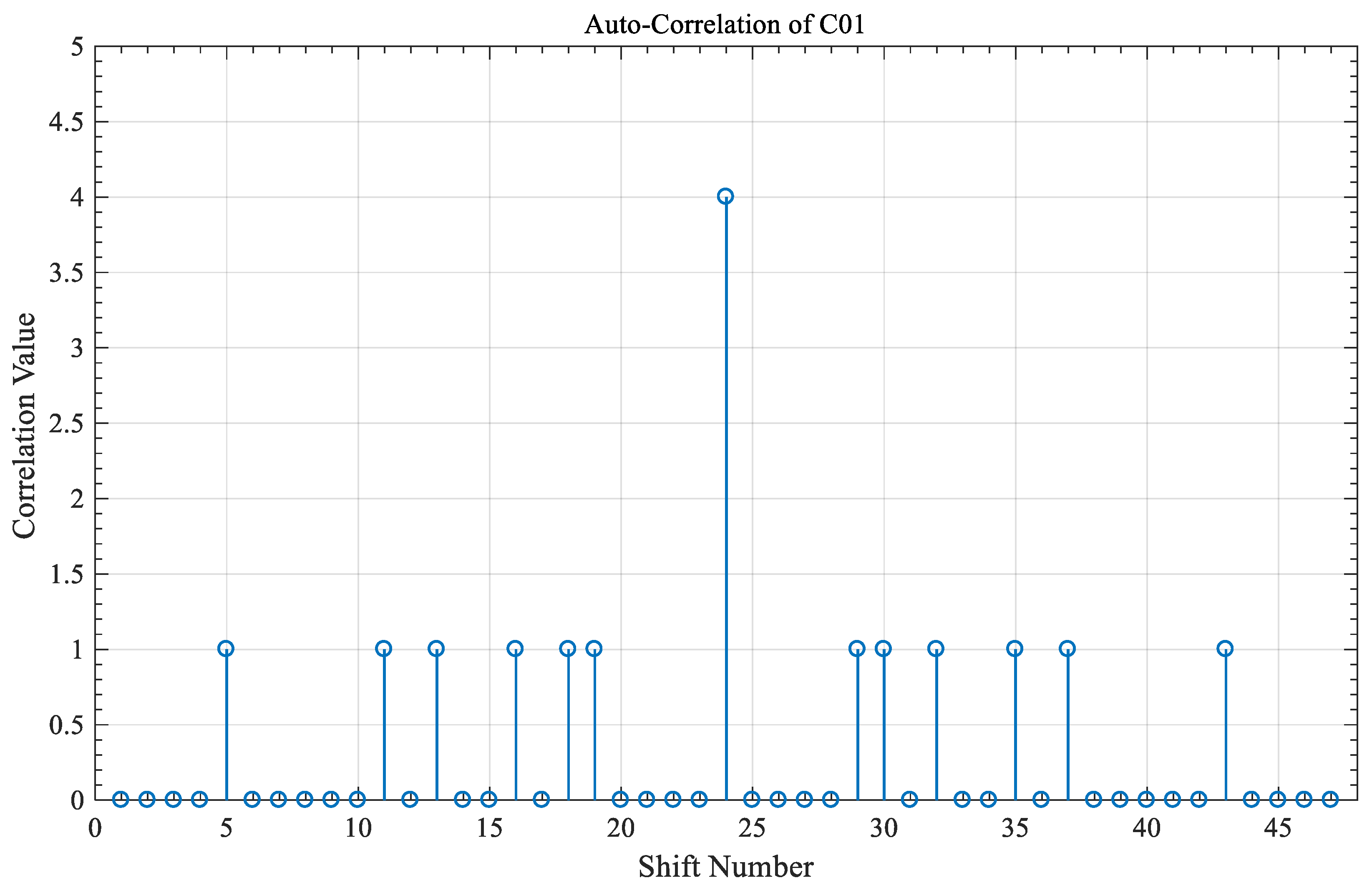
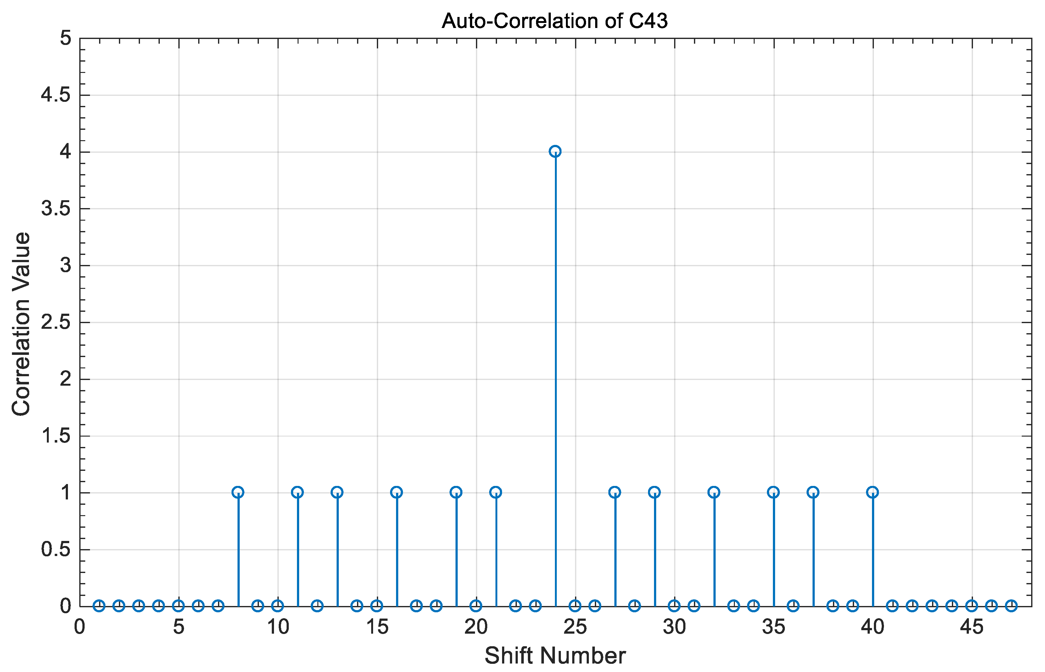
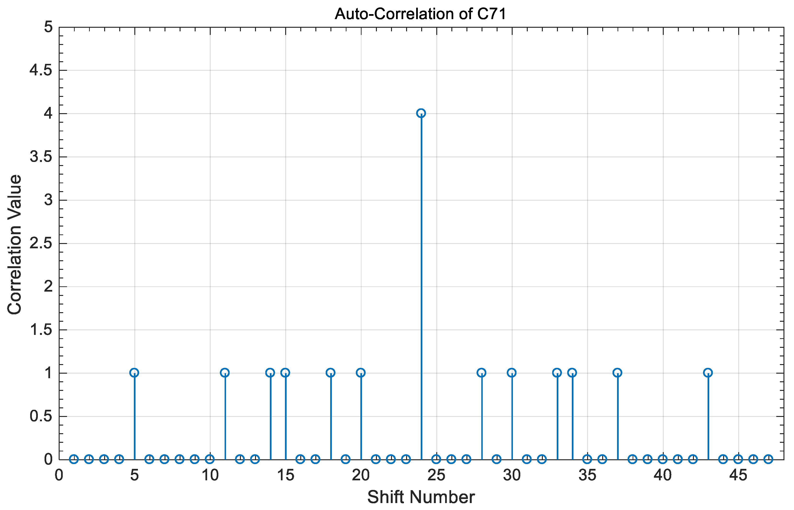
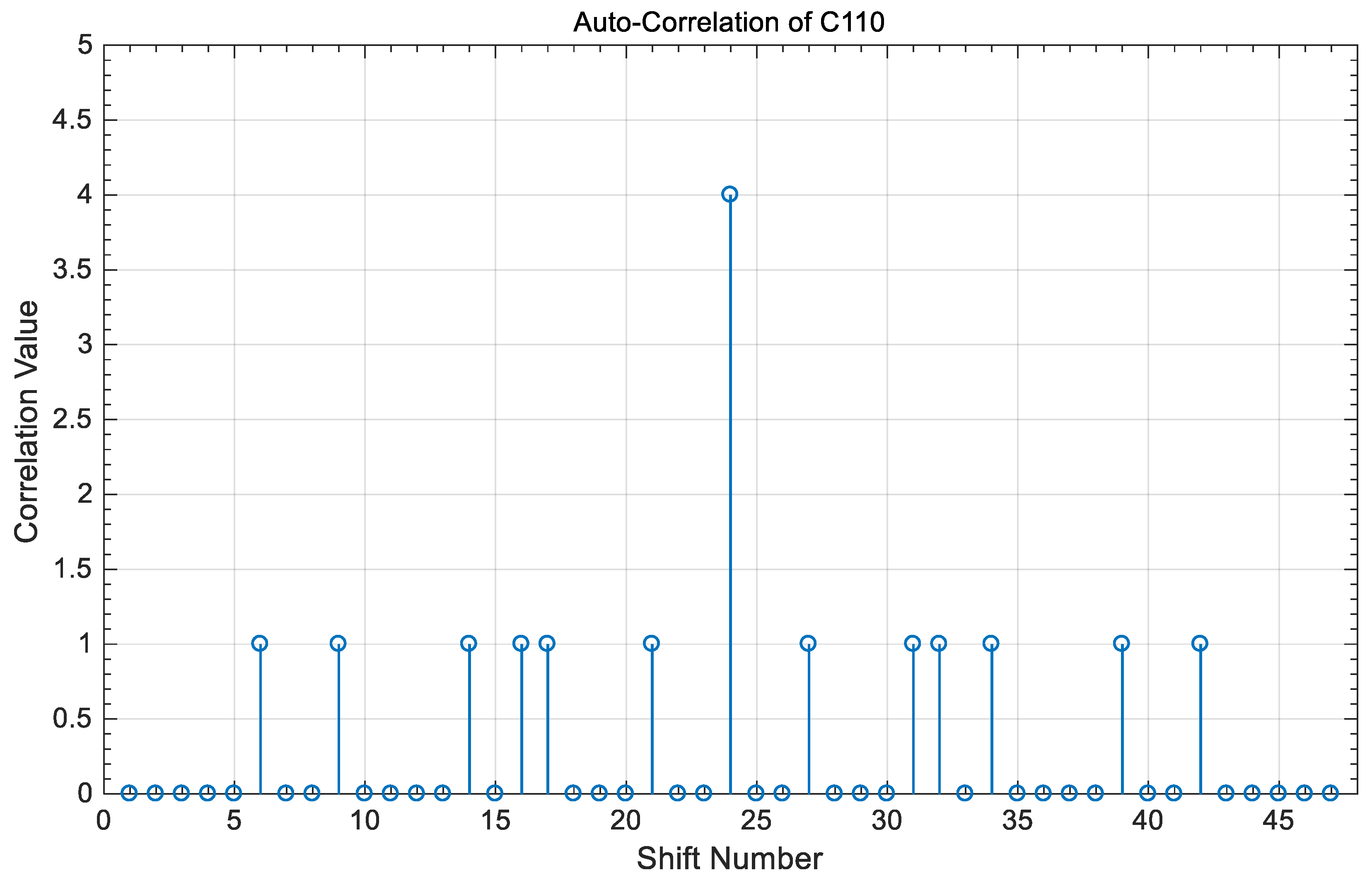
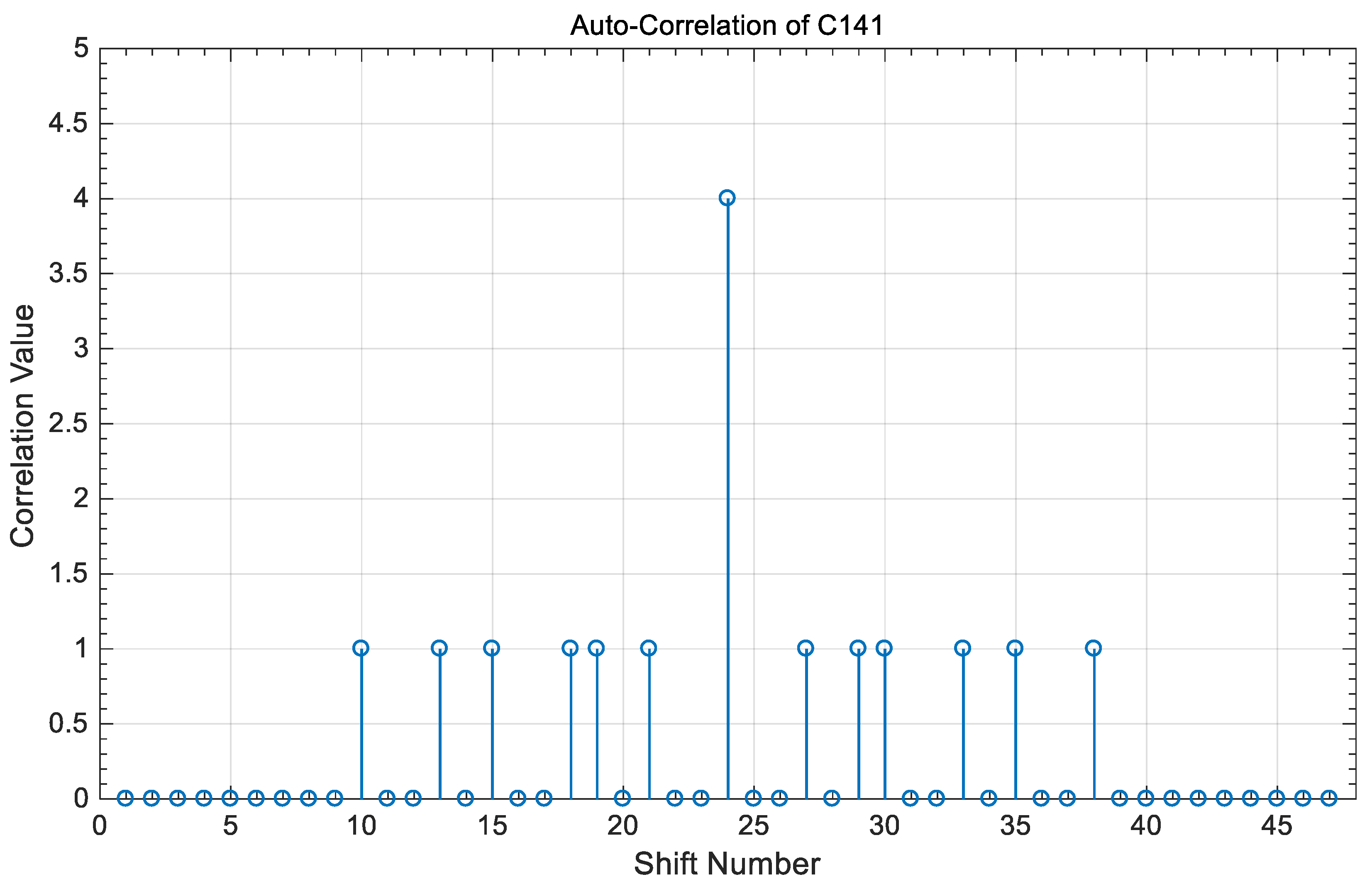
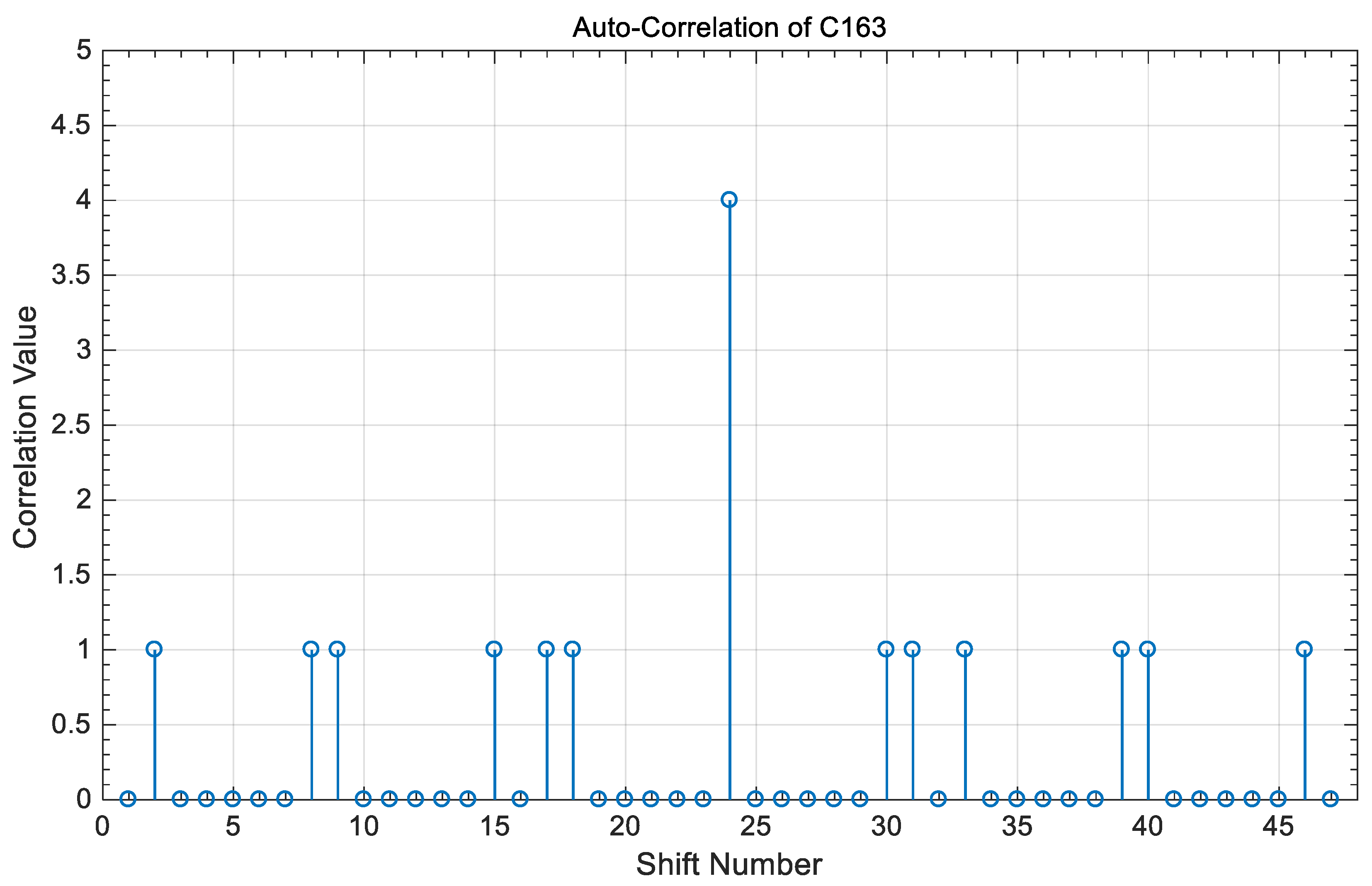
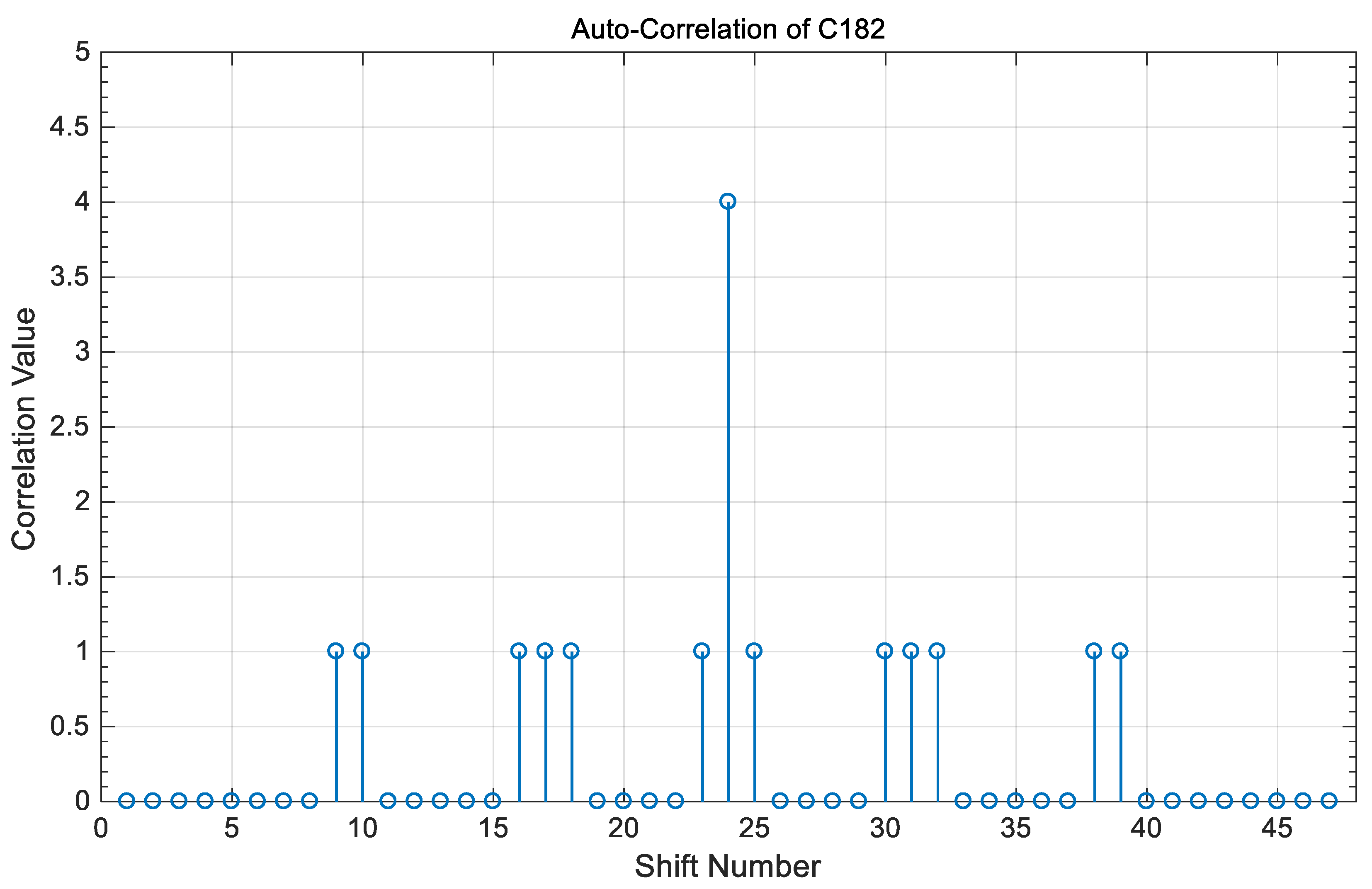
The simulations in this section are performed to test the auto- and cross-correlation properties of the proposed HPC family at every synchronized time which is equal to the encoded bit time duration and to the time that represents the code sequence length. Figure 1, Figure 2, Figure 3, Figure 4, Figure 5, Figure 6 and Figure 7 show the auto-correlation property of the HPC sequences , , , , , , and respectively. The results illustrate that the auto-correlation peak value is equal to “Four”. Such value represents the number of code words in each code sequence belonging to the HPC family. This value can be increased by increasing the number of code words. It is noted that the side lobe values on both sides of the peak value are limited to either “ZERO” or “ONE” in all results. These results are better than the results obtained from MPC and OOC families.
Figure 8, Figure 9, Figure 10, Figure 11, Figure 12 and Figure 13 represent the value of the cross-correlation between two code sequences in the same group. It is clear that for every synchronized time referred to the shift number “24”, the cross-correlation value is “ZERO”. This achieves perfect orthogonality and zero interference at the receiver side.
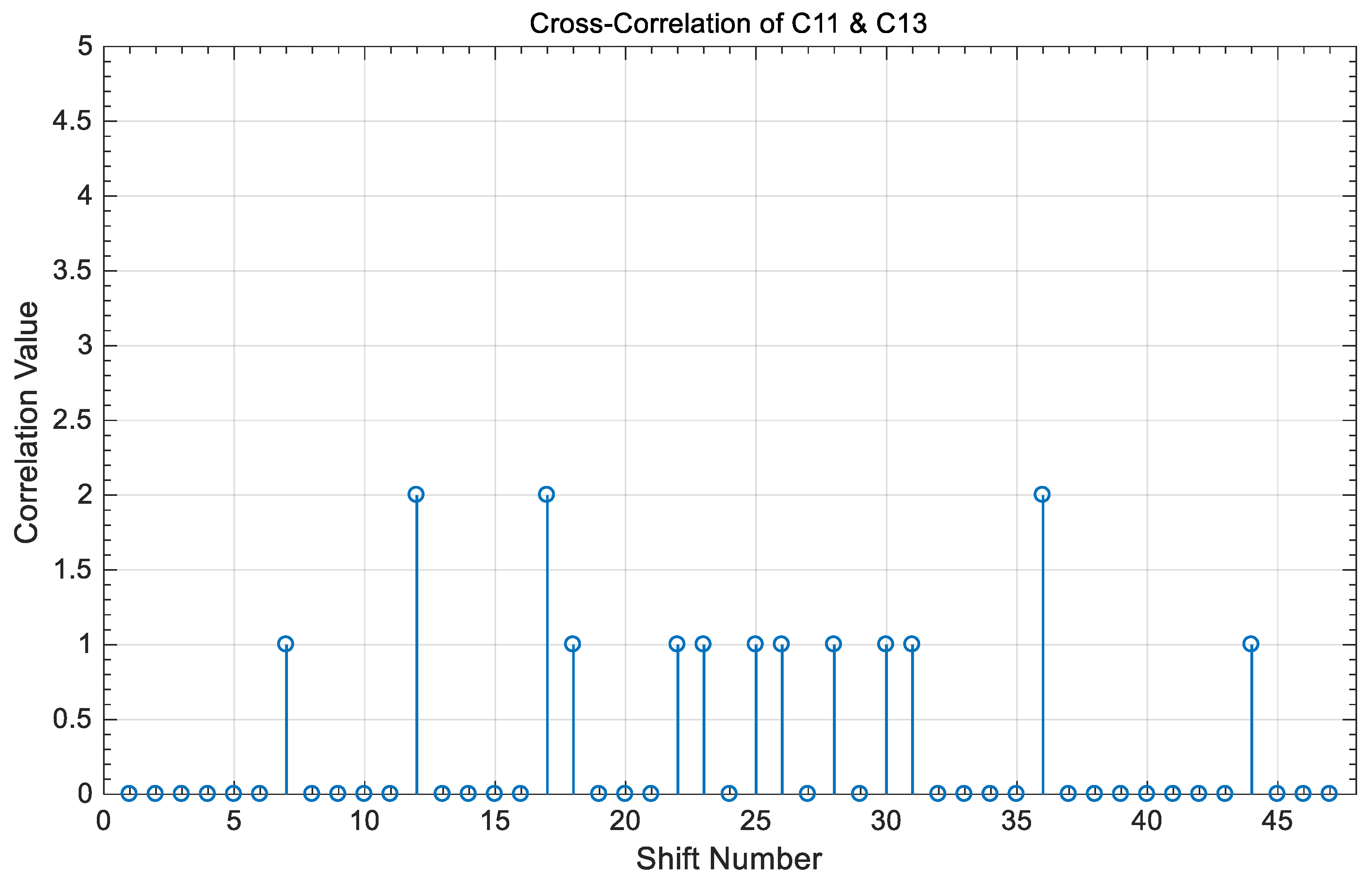
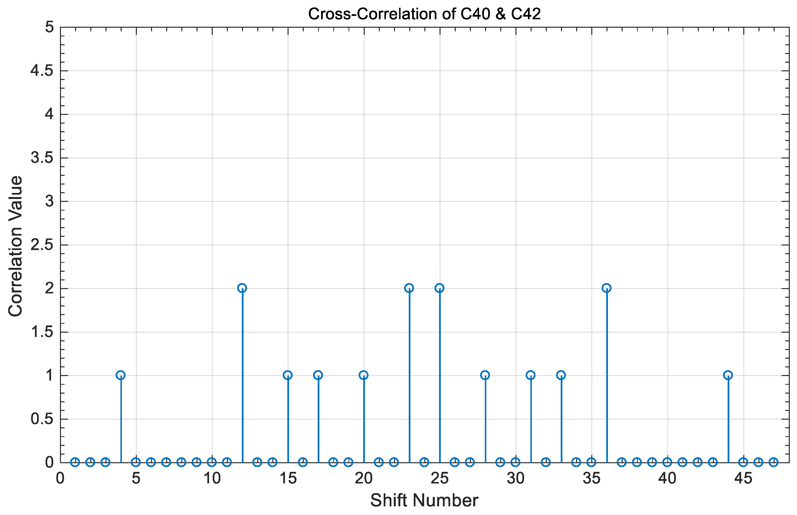
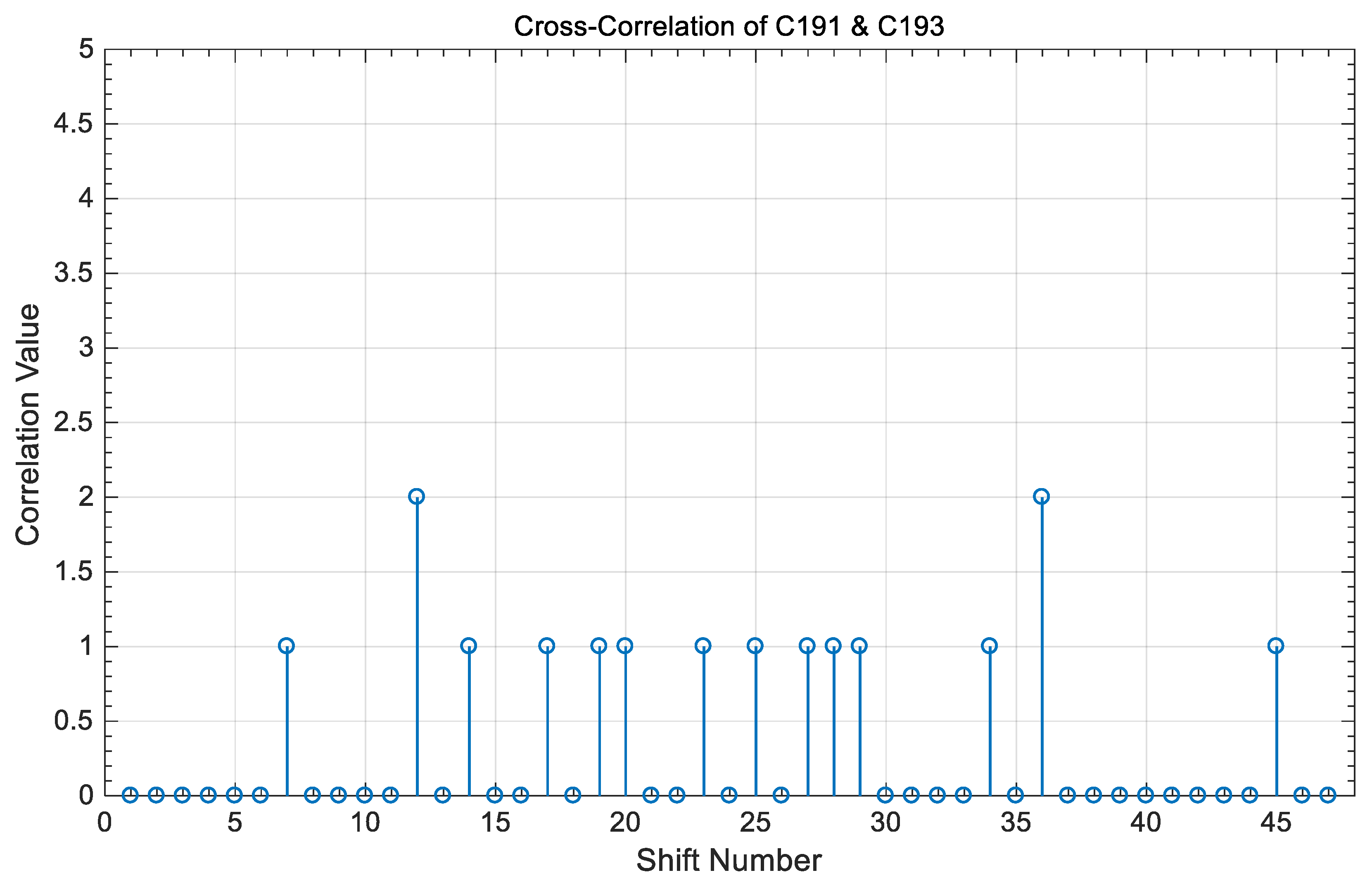
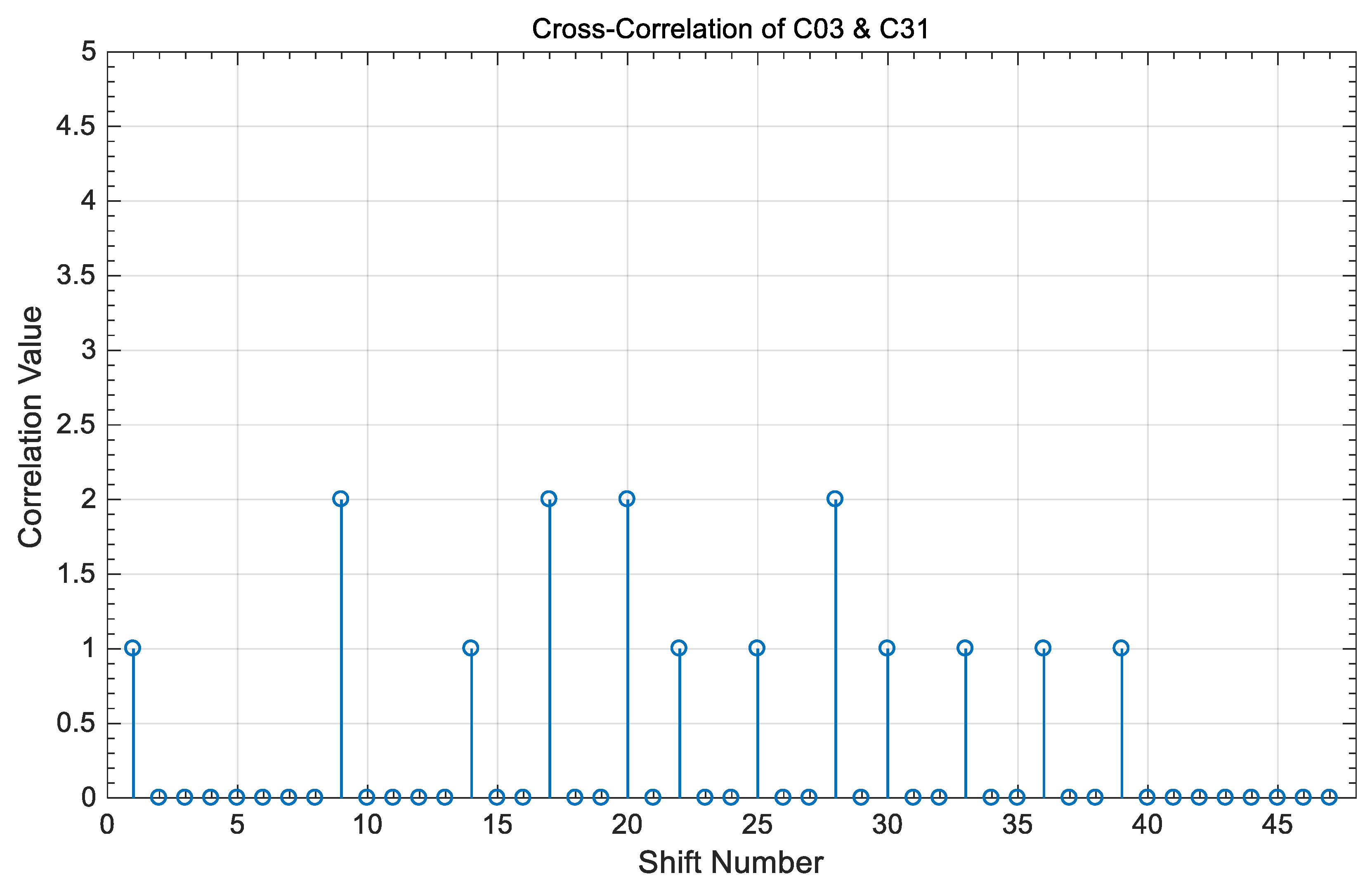
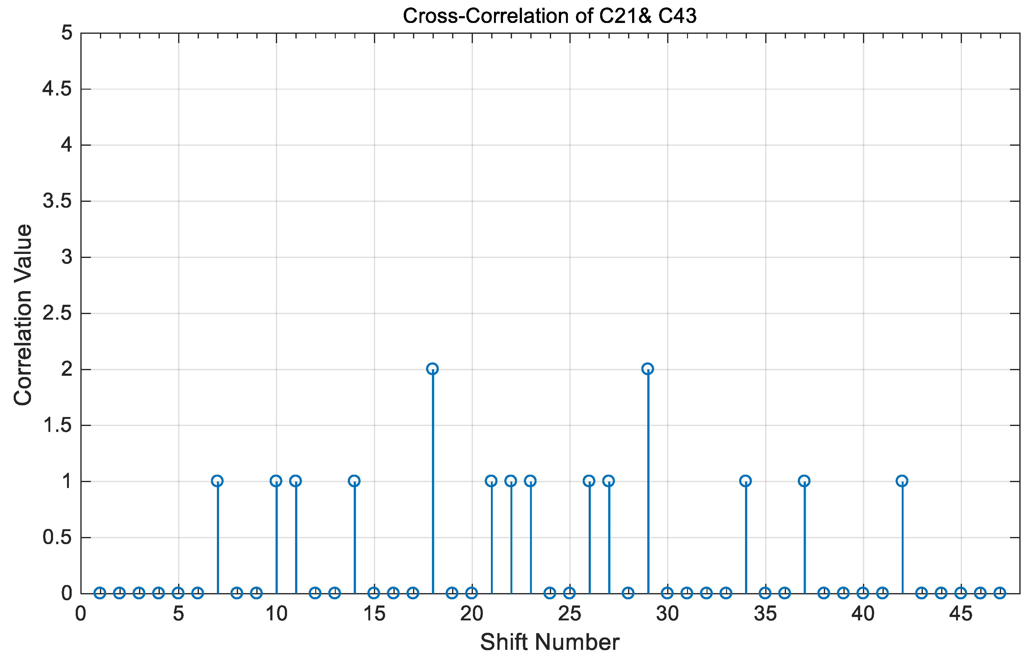
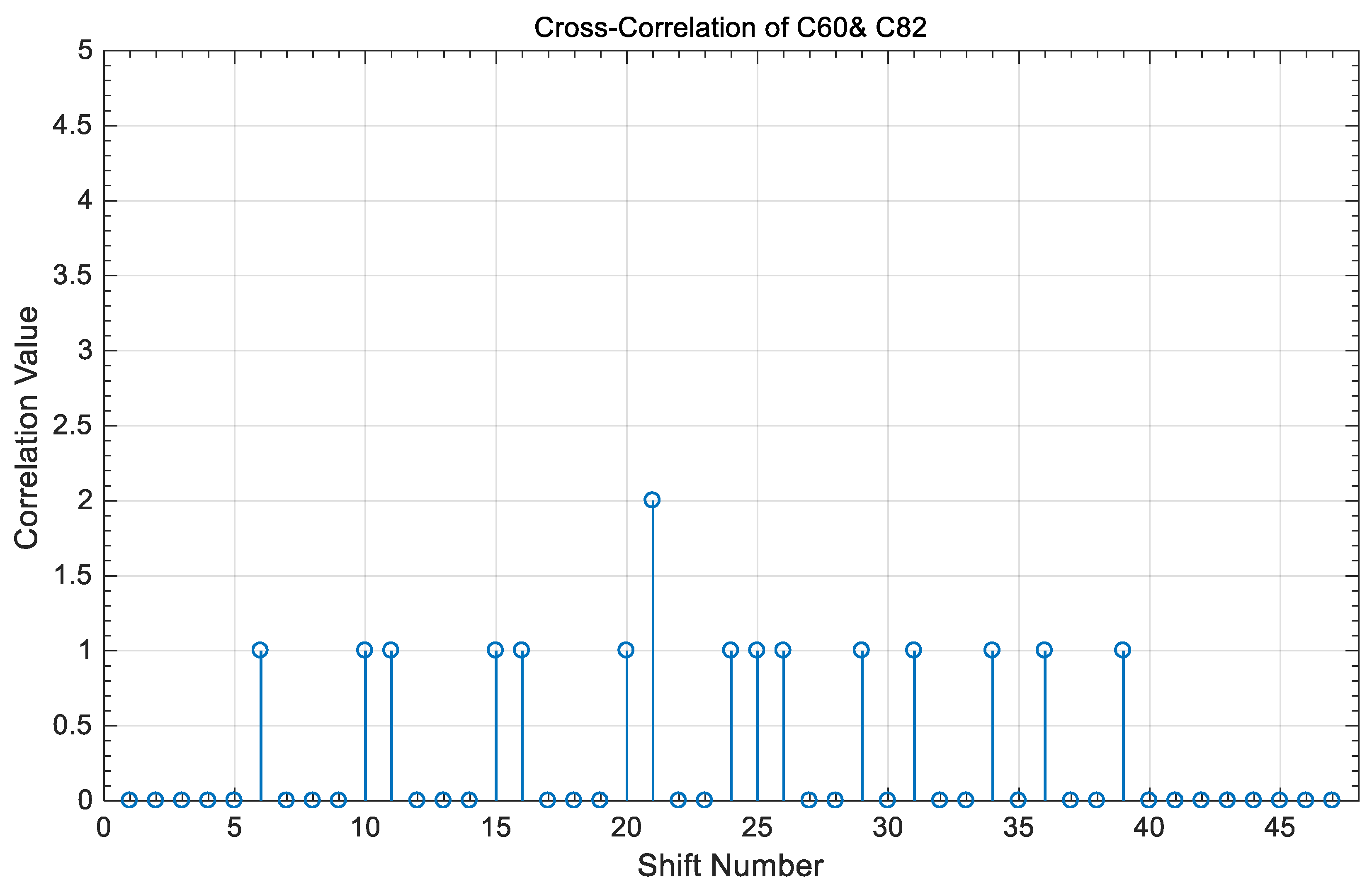
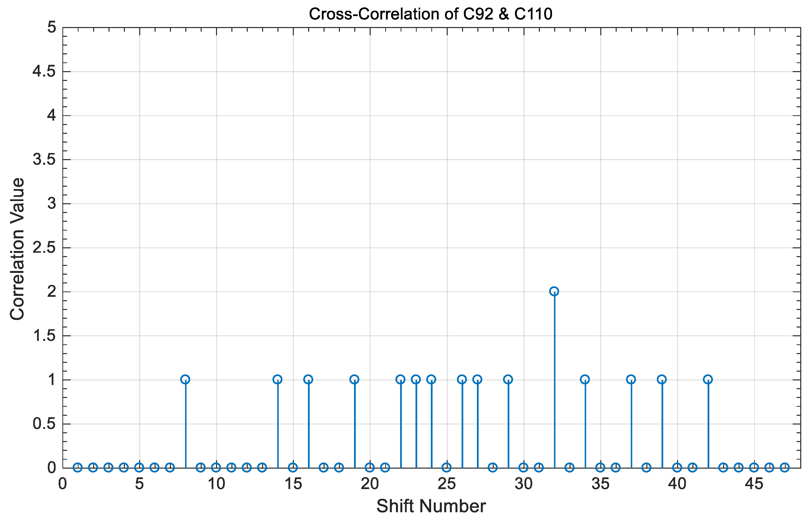
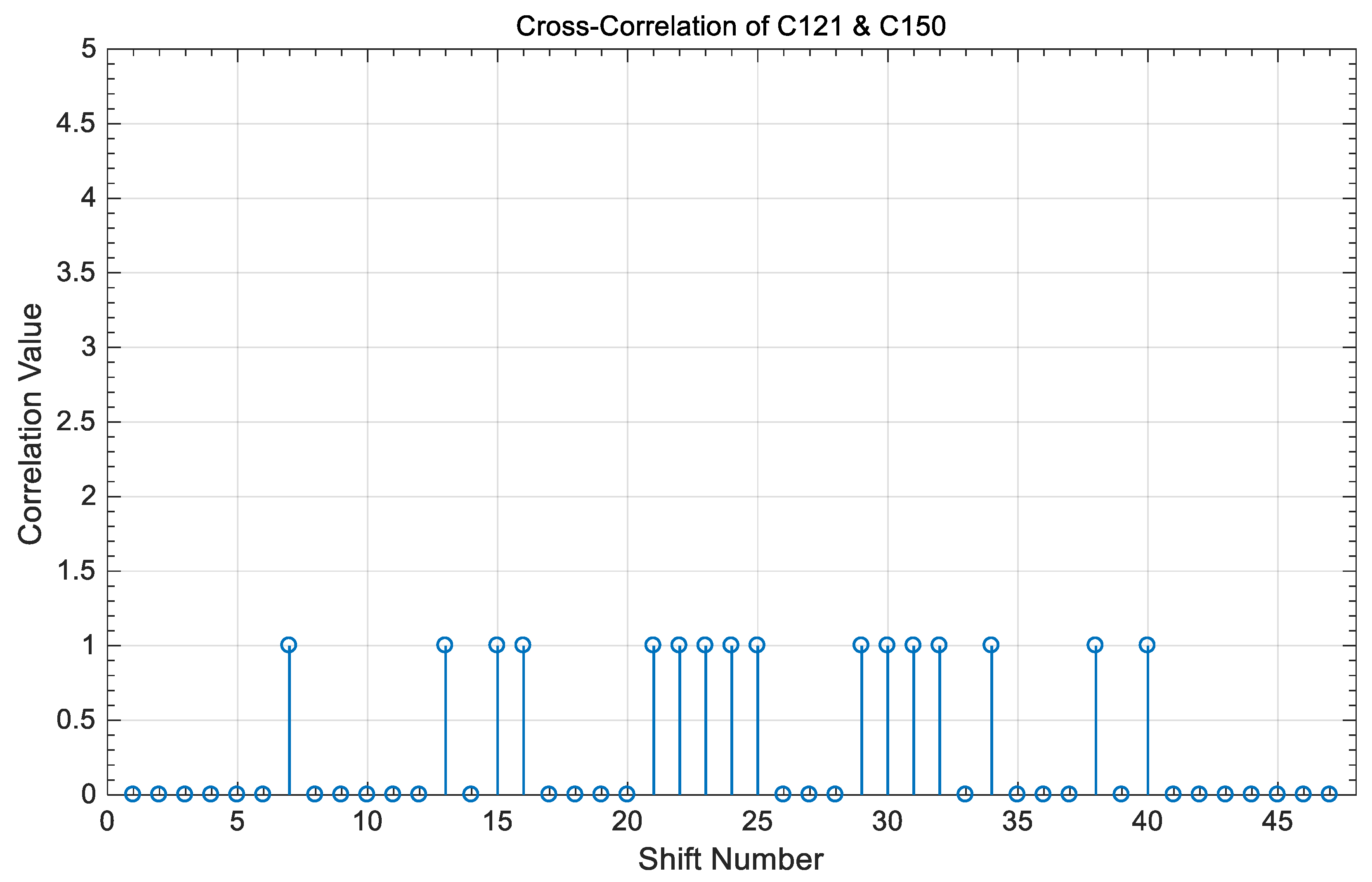
The cross-correlation property between two code sequences from two different groups are illustrated in Figure 14, Figure 15, Figure 16, Figure 17, Figure 18 and Figure 19. These results show that the cross-correlation value is “ZERO” or “ONE” at every synchronized time. If the HPC sequences are applied to the asynchronous OCDMA network, each user can communicate in the network at unique time slots that cause out-of-phase and undesirable correlation values, as shown between each synchronized time.
5. The Proposed OCDMA System Model
Figure 20 shows the proposed OCDMA transceiver system architecture based on the HPC. To prevent the pulse spreading during the optical fiber channel, the data is first PPM modulated. Each PPM chip is spread by the proposed HPC sequence of length L and weight W and then is fed to a star coupler optical channel to broadcast it [54]. The system multiplicity M is the power control factor that controls the optical power level at the receiver. The total number of available code sequences is the most important factor for the system capacity calculation and throughput. Additionally, the MAI caused by the star coupler optical channel is also the important factor that affects the BER performance and system capacity and is considered in the performance analysis.
6. BER Performance Analysis
Each HPC sequence is characterized by the following parameters:
- Code length equal to , where is the prime number and n is the number of the different prime numbers used for the code construction.
2n, is the number of code words in each code sequence generated.
The total number of sequences generated , where is the minimum prime number used for the code construction.
Throughout the analysis, it is assumed that is the maximum number of active users out of the number of sequences available, with the remaining number of users being inactive. In addition, is given as a random variable which is defined as [48,49]:
Thus,
Furthermore, the number of active users in the first group can be represented by a random variable , and is the variable that realizes . When user #2 is recommended, then and its probability function can be written as:
where umin = max(N + P1 − K, 1), and umax = min(N, P1).
Assume each PPM pulse having a number of photons Q that can be defined by . Furthermore, the random vector represents the amount of MAI interference, where lj is a random variable representing the number of pulses interfering the time slot number j. Additionally, w = (w0, w1, ……., wM−1)U is the vector that realizes the vector l and U = u.
The probability of the random vector l can be expressed as:
where .
In case of the PPM-OCDMA scheme, the BER performance can be expressed as:
According to the characteristics of HPC, Equation (5) can be modified as:
7. Throughput Analysis
The throughput calculation is mainly based on two important parameters such as the information rate and system capacity. It should be assumed that is the M-ary frame duration, is the HPC sequence length, and each time slot has duration which equals . Therefore, for different applications can be expressed as:
The throughput for variable , according to the provided application by the network, can be defined as:
where is the chip rate and is a factor that represents the probability of received bit correctly multiplied by the maximum throughput or the steady state value of the throughput. The user throughput product measures the total information rate transmitted by all users in a network. This product denoted by , but in practice, the parameters , , and are optimized in order to maximize the users-throughput product.
8. EVM Analysis
The error vector magnitude (EVM) is a new important metric for measuring the quality of the optical signal with BER and throughput performances. For N randomly transmitted symbols, EVM is defined by the root mean square value of the difference between the received error vector and the ideal transmitted vector [55]. For M-ary modulation the BER can be expressed as a function of the EVM as [56,57]:
For more simplicity, EVM can also be expressed as:
9. Simulation Results
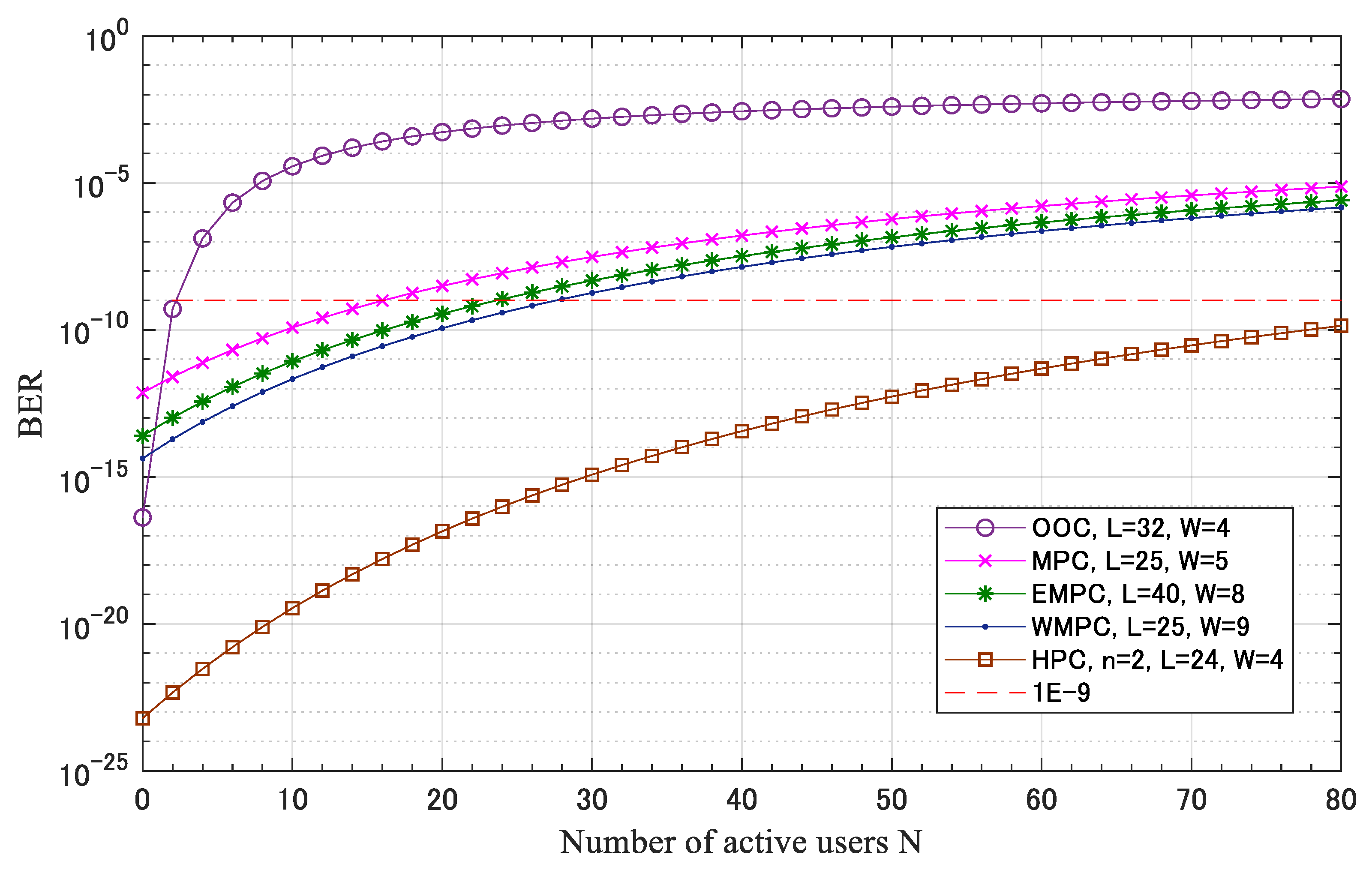
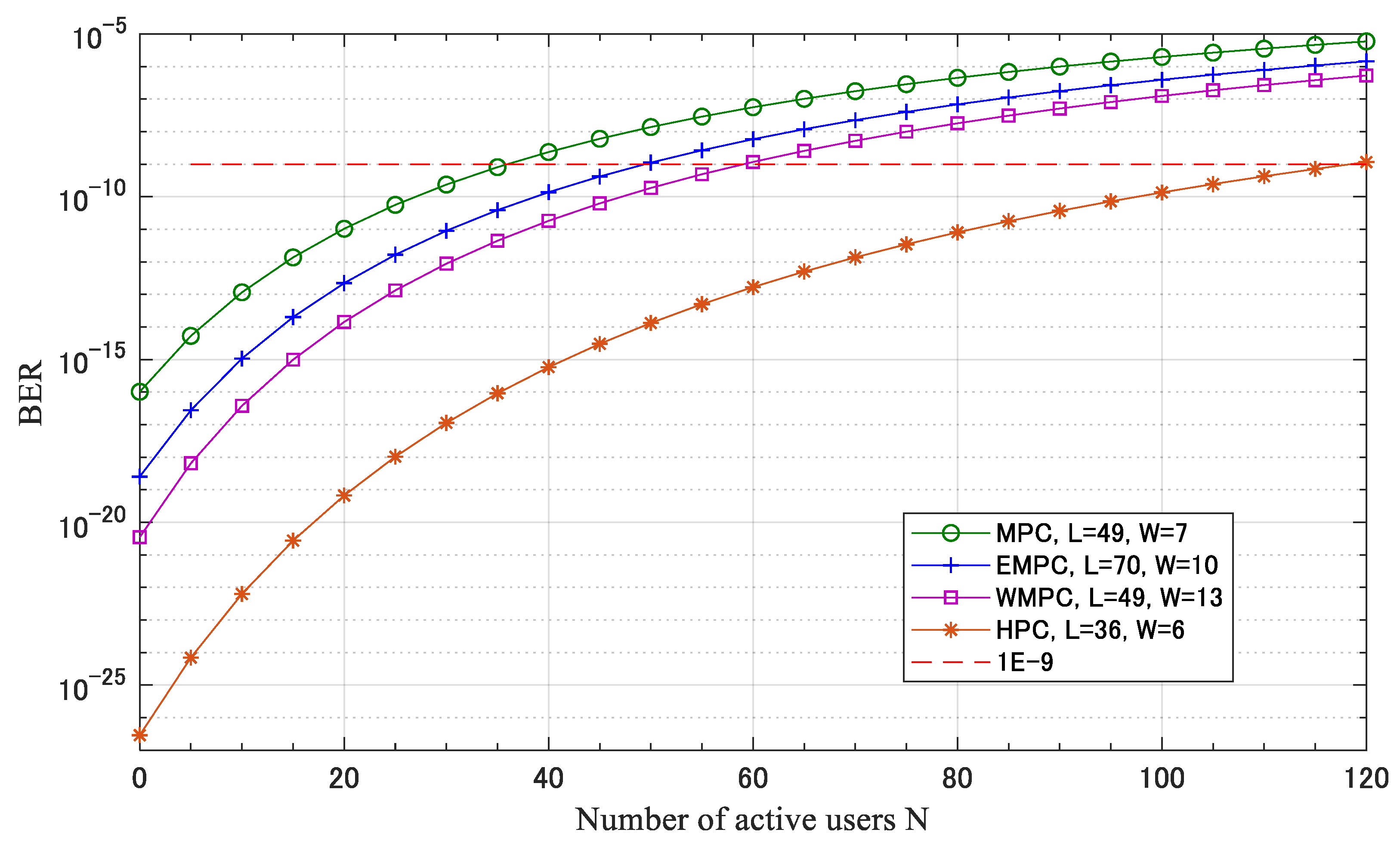
Figure 21 shows the BER performance of the OCDMA system versus the number of active users based on the proposed HPC. The graph compares HPC with OOC, MPC, EMPC, and WMPC (please refer to legend). The result illustrates that when n = 2, L = 24, and W = 4 the HPC outperforms the other codes and the OCDMA can accommodate 80 users at BER equal to 10−10. This means lower MAI as a result of good code correlation characteristics. If the code length and code weight are increased, the system can accommodate a higher number of active users at slightly higher BER due to the incremental increase in the MAI. Despite this increase, the proposed code is still better than the other codes as shown in Figure 22.
Considering the optimum value of BER and the value of system multiplicity M, Figure 23 presents the system users-throughput product against the number of active users N in case of the proposed HPC in comparison with the existing MPC. The results show that at any value of N, the system throughput product decreases as the system multiplicity increases. In addition, the results show that when the HPC is used the users-throughput product slightly increases as the number of active users N increases. This due to the dependence of N and the code length L on the used prime numbers On the other hand, when the MPC is used the users-throughput product remains the same when the number of active users increase, which is due to the minimum available number of codes. Finally, the system throughput product in the case of HPC outperforms the throughput product in the case of MPC due to the difference in the chip rate illustrated in the previous results in Figure 22 and the higher number of codes available.
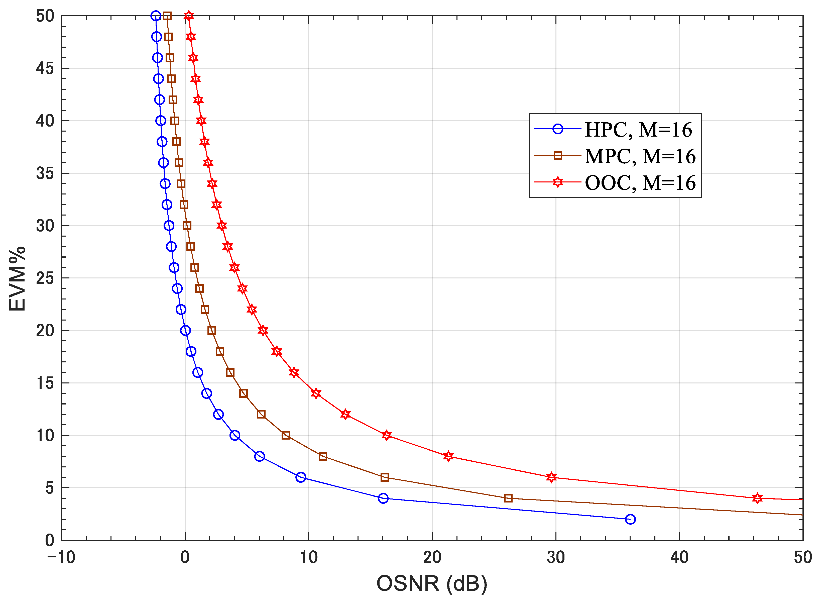
Figure 24 shows EVM% versus the OSNR. This illustrates that at any value of EVM, the proposed HPC code outperforms the other codes. Moreover, at any value of OSNR, the error magnitude is lowest when the proposed code is recommended. For example, at 10 dB OSNR, the values of EVM% are 5%, 8%, and 15% for HPC, MPC, and OOC, respectively. This is because the good correlation properties achieve the minimum MAI and better BER.
10. Conclusions
The new address sequence for the SI-OCDMA network which refers to HPC was proposed and evaluated in the communication systems in terms of BER and users-throughput product. The code construction principles and their correlation properties were presented. Furthermore, the code construction results proved that the generated number of codes in the HPC family is much greater than the number of codes generated in the other existing code families at the same code length. Moreover, the proposed code has the potential to change its length and weight while maintaining its excellent correlation properties. In addition, the good correlation characteristics of the HPC led to: (1) achieve a minimum amount of MAI; and (2) improve the network EVM and BER performance in comparison with the OOC and MPC at a higher number of users. Finally, the HPC has the potential to enhance the OCDMA network capacity.
Author Contributions
Conceptualization, M.A.M.; methodology, M.A.M.; software M.A.M.; validation, M.A.M. and M.H.A.; formal analysis, M.A.M.; investigation, M.A.M.; resources, M.A.M. and M.H.A.; data curation, M.A.M. and M.H.A.; writing—original draft preparation, M.A.M.; writing—review and editing, M.A.M. and M.H.A.; visualization, M.A.M.; supervision, M.H.A.; project administration, M.A.M. and M.H.A. All authors have read and agreed to the published version of the manuscript.
Funding
This research received no external funding.
Conflicts of Interest
The authors declare no conflict of interest.
References
- Alderson, T.L. n-dimensional optical orthogonal codes, bounds and optimal constructions. Appl. Algebra Eng. Commun. Comput. 2019, 30, 373–386. [Google Scholar] [CrossRef] [Green Version]
- Alderson, T.L. 3-Dimensional Optical Orthogonal Codes with Ideal Autocorrelation-Bounds and Optimal Constructions. IEEE Trans. Inf. Theory 2017, 64, 4392–4398. [Google Scholar] [CrossRef] [Green Version]
- Feng, T.; Chang, Y. Combinatorial Constructions for Optimal Two-Dimensional Optical Orthogonal Codes With λ = 2. IEEE Trans. Inf. Theory 2011, 57, 6796–6819. [Google Scholar] [CrossRef]
- Wang, X.; Chang, Y.; Feng, T. Optimal 2-D (n × m,3,2,1)-optical Orthogonal Codes. IEEE Trans. Inf. Theory 2012, 59, 710–725. [Google Scholar] [CrossRef]
- Cai, H.; Liang, H.; Tang, X. Constructions of Optimal 2-D Optical Orthogonal Codes via Generalized Cyclotomic Classes. IEEE Trans. Inf. Theory 2014, 61, 688–695. [Google Scholar] [CrossRef]
- Chung, J.-H.; Yang, K. New Families of Optimal Variable-Weight Optical Orthogonal Codes with High Weights. IEEE Trans. Inf. Theory 2015, 61, 4511–4517. [Google Scholar] [CrossRef]
- Li, X.; Lu, L. General Construction Method of Multilength Optical Orthogonal Codes with Arbitrary Cross-Correlation Constraint for OCDMA Multimedia Network. J. Opt. Commun. Netw. 2015, 7, 156–163. [Google Scholar] [CrossRef]
- Morsy, M.A.; Hassan, K.M.; Morshed, A.H.; Elhennawy, A. Analysis of Optical Code Division Multiple Access Passive Networks for Different Encoder Delay Elements. In Proceedings of the 2006 International Conference on Computer Engineering and Systems, Cairo, Egypt, 5–7 November 2006; pp. 294–299. [Google Scholar]
- Farghal, A.E.A.; Shalaby, H.M.H.; Kato, K.; Pokharel, R.K. Performance Analysis of Multicode OCDM Networks Supporting Elastic Transmission with QoS Differentiation. IEEE Trans. Commun. 2015, 64, 741–752. [Google Scholar] [CrossRef]
- Raddo, T.; Sanches, A.L.; Monroy, I.T.; Borges, B.-H.V. Throughput Performance Evaluation of Multiservice Multirate OCDMA in Flexible Networks. IEEE Photonics J. 2016, 8, 1–15. [Google Scholar] [CrossRef] [Green Version]
- Liu, X.-J.; Xia, S.-T.; Fu, F.-W. Reconstruction Guarantee Analysis of Basis Pursuit for Binary Measurement Matrices in Compressed Sensing. IEEE Trans. Inf. Theory 2017, 63, 2922–2932. [Google Scholar] [CrossRef]
- Bharti, A.Y.; Kar, S.; Jain, V.K. Performance analysis of wireless OCDMA multi-user system based on new 2-D code in presence of atmospheric turbulence and various weather conditions. In Proceedings of the 9th International Conference on Communication Systems and Networks (COMSNETS), Bengaluru, India, 4–8 January 2017; pp. 109–115. [Google Scholar]
- Alderson, T.L.; Mellinger, K.E. Families of Optimal OOCs with λ = 2. IEEE Trans. Inf. Theory 2008, 54, 3722–3724. [Google Scholar] [CrossRef]
- Yang, G.-C.; Kwong, W. Performance analysis of optical CDMA with prime codes. Electron. Lett. 1995, 31, 569–570. [Google Scholar] [CrossRef]
- Karbassian, M.M.; Ghafouri-Shiraz, H. Fresh Prime Codes Evaluation for Synchronous PPM and OPPM Signaling for Optical CDMA Networks. J. Lightwave Technol. 2007, 25, 1422–1430. [Google Scholar] [CrossRef]
- Wen, J.-H.; Lin, J.-Y.; Liu, C.-Y. Modified prime-hop codes for optical CDMA systems. IEE Proc. Commun. 2003, 150, 404–408. [Google Scholar] [CrossRef]
- Huang, W.-J.; Niu, C.-T.; Lin, C.-H.; Wu, J. Spatial/Spectral OCDMA System Using Partial Modified Prime Codes and Error-Correction Codes. J. Lightwave Technol. 2008, 26, 3030–3040. [Google Scholar] [CrossRef]
- Yang, C.-C. Optical CDMA Passive Optical Network Using Prime Code with Interference Elimination. IEEE Photonics Technol. Lett. 2007, 19, 516–518. [Google Scholar] [CrossRef]
- Ding, C.; Pless, V. Cyclotomy and duadic codes of prime lengths. IEEE Trans. Inf. Theory 2002, 45, 453–466. [Google Scholar] [CrossRef]
- Ding, C. Cyclotomic Constructions of Cyclic Codes with Length Being the Product of Two Primes. IEEE Trans. Inf. Theory 2012, 58, 2231–2236. [Google Scholar] [CrossRef] [Green Version]
- Karbassian, M.M.; Kueppers, F. Synchronous Optical CDMA Networks Capacity Increase Using Transposed Modified Prime Codes. J. Lightwave Technol. 2010, 28, 2603–2610. [Google Scholar] [CrossRef]
- Morsy, M.A. Analysis and design of weighted MPC in incoherent synchronous OCDMA network. Opt. Quantum Electron. 2018, 50, 387. [Google Scholar] [CrossRef]
- Hong, C.-F.; Yang, G.-C. Concatenated prime codes. IEEE Commun. Lett. 1999, 3, 260–262. [Google Scholar] [CrossRef]
- Zoualfaghari, M.H.; Ghafouri-Shiraz, H. Uniform Cross-Correlation Modified Prime Code for Applications in Synchronous Optical CDMA Communication Systems. J. Lightwave Technol. 2012, 30, 2955–2963. [Google Scholar] [CrossRef]
- Yang, G.-C.; Kwong, W.C. Performance Analysis of Extended Carrier-Hopping Prime Codes for Optical CDMA. IEEE Trans. Commun. 2005, 53, 876–881. [Google Scholar] [CrossRef]
- Yang, C.-C. Optical CDMA coding scheme with a large size of code space. IEEE Commun. Lett. 2009, 13, 145–147. [Google Scholar] [CrossRef]
- Fujiwara, Y.; van den Driessche, P. Quantum Synchronizable Codes from Finite Geometries. IEEE Trans. Inf. Theory 2014, 60, 7345–7354. [Google Scholar] [CrossRef] [Green Version]
- Oggier, F.; Sole, P.; Belfiore, J.-C. Codes Over Matrix Rings for Space-Time Coded Modulations. IEEE Trans. Inf. Theory 2012, 58, 734–746. [Google Scholar] [CrossRef] [Green Version]
- Ding, C.; Kohel, D.; Ling, S. Elementary 2-group character codes. IEEE Trans. Inf. Theory 2000, 46, 280–284. [Google Scholar] [CrossRef]
- Hamarsheh, M.; Shalaby, H.; Abdullah, M. Design and analysis of a dynamic code division multiple access communication system based on tunable optical filter. J. Lightwave Technol. 2005, 23, 3959–3965. [Google Scholar] [CrossRef] [Green Version]
- Yen, C.-T.; Chen, C.-M. A study of three-dimensional optical code-division multiple-access for optical fiber sensor networks. Comput. Electr. Eng. 2016, 49, 136–145. [Google Scholar] [CrossRef]
- Liu, F.; Karbassian, M.M.; Ghafouri-Shiraz, H. Novel family of prime codes for synchronous optical CDMA. Opt. Quantum Electron. 2007, 39, 79–90. [Google Scholar] [CrossRef]
- Lalmahomed, A.; Karbassian, M.; Ghafouri-Shiraz, H. Performance Analysis of Enhanced-MPC in Incoherent Synchronous Optical CDMA. J. Lightwave Technol. 2009, 28, 39–46. [Google Scholar] [CrossRef]
- Park, E.; Mendez, A.; Garmire, E. Temporal/spatial optical CDMA networks-design, demonstration, and comparison with temporal networks. IEEE Photonics Technol. Lett. 1992, 4, 1160–1162. [Google Scholar] [CrossRef]
- Yu, K.; Park, N. Design of new family of two-dimensional wavelength-time spreading codes for optical code division multiple access networks. Electron. Lett. 1999, 35, 830–831. [Google Scholar] [CrossRef]
- Mendez, A.J.; Gagliardi, R.M.; Hernandez, V.J.; Bennett, C.V.; Lennon, W.J. Design and performance analysis of wavelength/time (W/T) matrix codes for optical CDMA. J. Lightwave Technol. 2003, 21, 2524–2533. [Google Scholar] [CrossRef]
- Yang, C.-C.; Huang, J.-F. Two-dimensional M-matrices coding in spatial/frequency optical CDMA networks. IEEE Photonics Technol. Lett. 2003, 15, 168–170. [Google Scholar] [CrossRef]
- Heo, H.; Min, S.; Won, Y.; Yeon, Y.; Kim, B.; Kim, B. A New Family of 2-D Wavelength–Time Spreading Code for Optical Code-Division Multiple-Access System with Balanced Detection. IEEE Photonics Technol. Lett. 2004, 16, 2189–2191. [Google Scholar] [CrossRef]
- Gu, F.-R.; Wu, J. Construction of two-dimensional wavelength/time optical orthogonal codes using difference family. J. Lightwave Technol. 2005, 23, 3642–3652. [Google Scholar] [CrossRef]
- Lin, C.-H.; Wu, J.; Yang, C.-L. Noncoherent Spatial/Spectral Optical CDMA System with Two-Dimensional Perfect Difference Codes. J. Light Technol. 2005, 23, 3966–3980. [Google Scholar]
- Shurong, S.; Yin, H.; Wang, Z.; Xu, A. A new family of 2-D optical orthogonal codes and analysis of its performance in optical CDMA access networks. J. Lightwave Technol. 2006, 24, 1646–1653. [Google Scholar] [CrossRef]
- Morelle, M.; Goursaud, C.; Julien-Vergonjanne, A.; Aupetit-Berthelemot, C.; Cances, J.-P.; Dumas, J.-M.; Guignard, P. 2-Dimensional optical CDMA system performance with parallel interference cancellation. Microprocess. Microsyst. 2007, 31, 215–221. [Google Scholar] [CrossRef]
- Yang, C.-C.; Huang, J.-F.; Chiu, I.-M. Performance Analyses on Hybrid MQC/M-Sequence Coding Over Frequency/Spatial Optical CDMA System. IEEE Trans. Commun. 2007, 55, 40–43. [Google Scholar] [CrossRef]
- Tien, J.-H.; Yang, G.-C.; Chang, C.-Y.; Kwong, W.C. Design and Analysis of 2-D Codes with the Maximum Cross-Correlation Value of Two for Optical CDMA. J. Lightwave Technol. 2008, 26, 3632–3639. [Google Scholar] [CrossRef]
- Yeh, B.-C.; Lin, C.-H.; Yang, C.-L.; Wu, J. Noncoherent Spectral/Spatial Optical CDMA System Using 2-D Diluted Perfect Difference Codes. J. Lightwave Technol. 2009, 27, 2420–2432. [Google Scholar]
- Yin, H.; Ma, L.; Li, H.; Zhu, L. A new family of 2D wavelength/time codes with large cardinality for incoherent spectral amplitude coding OCDMA networks and analysis of its performance. Photonic Netw. Commun. 2010, 19, 204–211. [Google Scholar] [CrossRef]
- Morsy, M.A.; Alsayyari, A. BER Performance of OCDMA System Based on Optimized 2D PhC Passive Encoder. IET Commun. 2020, 14, 1268–1274. [Google Scholar] [CrossRef]
- Ismail, M.A.M.; Alsayyari, A.; Galal, O.H. Performance analysis of optical code division multiple access networks for multimedia applications using multilength weighted modified prime codes. Opt. Eng. 2019, 58, 035101. [Google Scholar] [CrossRef]
- Morsy, M.A.; Alsayyari, A.S. Multi-rate OCDMA system BER performance evaluations for different ML-code sequences. Opt. Quantum Electron. 2019, 51, 198. [Google Scholar] [CrossRef]
- Morsy, M.A.; Alsayyari, A.S. Performance analysis of incoherent PPM-OCDMA networks based on optimised modified prime code for multimedia applications. IET Commun. 2020, 14, 4014–4021. [Google Scholar] [CrossRef]
- Morsy, M.A.; Alsayyari, A.S. Performance analysis of coherent BPSK-OCDMA wireless communication system. Wirel. Netw. 2020, 26, 4491–4505. [Google Scholar] [CrossRef]
- Morsy, M.A.; Alsayyar, A.S. Performance analysis of OCDMA wireless communication system based on double length modified prime code for security improvement. IET Commun. 2020, 14, 1139–1146. [Google Scholar] [CrossRef]
- Morsy, M.A.; Alsayyari, A.S. Performance Control of Incoherent Synchronous PPM-OCDMA Networks. In Proceedings of the 2019 2nd IEEE Middle East and North Africa COMMunications Conference (MENACOMM), Manama, Bahrain, 19–21 November 2019; pp. 1–4. [Google Scholar]
- Morsy, M.A.; Hadeel, S.A.R.; Al-Obaidan, H.M. Performance of Passive OCDMA Networks for Different Encoder/Decoder Delay Lines. Int. J. Opt. Appl. 2013, 3, 19–26. [Google Scholar]
- Nebendahl, B.; Schmogrow, R.; Josten, A.; Koenig, S.; Freude, W.; Koos, C.; Meyer, J.; Dreschmann, M.; Huebner, M.; Hillerkuss, D.; et al. EVM as new quality metric for optical modulation analysis. In Proceedings of the 2013 Saudi International Electronics, Communications and Photonics Conference, Riyadh, Saudi Arabia, 27–30 April 2013; pp. 1–4. [Google Scholar]
- Schmogrow, R.; Nebendahl, B.; Winter, M.; Josten, A.; Hillerkuss, D.; Koenig, S.; Meyer, J.; Dreschmann, M.; Huebner, M.; Koos, C.; et al. Error Vector Magnitude as a Performance Measure for Advanced Modulation Formats. IEEE Photonics Technol. Lett. 2011, 24, 61–63. [Google Scholar] [CrossRef]
- Shafik, R.A.; Rahman, M.S.; Islam, A.H.M.R. On the Extended Relationships Among EVM, BER and SNR as Performance Metrics. In Proceedings of the 4th International Conference on Electrical and Computer Engineering, Dhaka, Bangladesh, 19–21 December 2006; pp. 408–411. [Google Scholar]
Figure 1.
Auto-correlation of sequence, .

Figure 2.
Auto-correlation of sequence, .

Figure 3.
Auto-correlation of sequence, .

Figure 4.
Auto-correlation of sequence, .

Figure 5.
Auto-correlation of sequence, .

Figure 6.
Auto-correlation of sequence, .

Figure 7.
Auto-correlation of sequence, .

Figure 8.
Cross-correlation between sequences in same group, .

Figure 9.
Cross-correlation between sequences in same group, .

Figure 10.
Cross-correlation between sequences in same group, .

Figure 11.
Cross-correlation between sequences in same group, .

Figure 12.
Cross-correlation between sequences in same group, .

Figure 13.
Cross-correlation between sequences in same group, .

Figure 14.
Cross-correlation between sequences from different groups, .

Figure 15.
Cross-correlation between sequences from different groups, .

Figure 16.
Cross-correlation between sequences from different groups, .

Figure 17.
Cross-correlation between sequences from different groups, .

Figure 18.
Cross-correlation between sequences from different groups, .

Figure 19.
Cross-correlation between sequences from different groups, .

Figure 20.
The proposed OCDMA system model.

Figure 21.
BER of OCDMA systems versus the number of active users N (n = 2, L = 24 and W = 4).

Figure 22.
BER of OCDMA systems versus the number of active users N (n = 3, L = 36 and W = 6).

Figure 23.
User throughput product versus the number of active users N.

Figure 24.
EVM% versus the OSNR for different coding schemes when M = 16.

Table 1.
Code sequences tree for P = 5.
| Folded Code Sequences | Code Sequences | ||||||
|---|---|---|---|---|---|---|---|
Table 2.
Code sequences tree for P = 7.
| Folded Code Sequences | Code Sequences | ||||||||||
|---|---|---|---|---|---|---|---|---|---|---|---|
| X62X02 | X02X62 | ||||||||||
| . | |||||||||||
| . | |||||||||||
Publisher’s Note: MDPI stays neutral with regard to jurisdictional claims in published maps and institutional affiliations. |
© 2021 by the authors. Licensee MDPI, Basel, Switzerland. This article is an open access article distributed under the terms and conditions of the Creative Commons Attribution (CC BY) license (https://creativecommons.org/licenses/by/4.0/).
Share and Cite
MDPI and ACS Style
Morsy, M.A.; Aly, M.H. A New Hybrid Prime Code for OCDMA Network Multimedia Applications. Electronics 2021, 10, 2705. https://doi.org/10.3390/electronics10212705
AMA Style
Morsy MA, Aly MH. A New Hybrid Prime Code for OCDMA Network Multimedia Applications. Electronics. 2021; 10(21):2705. https://doi.org/10.3390/electronics10212705
Chicago/Turabian StyleMorsy, Morsy A., and Moustafa H. Aly. 2021. "A New Hybrid Prime Code for OCDMA Network Multimedia Applications" Electronics 10, no. 21: 2705. https://doi.org/10.3390/electronics10212705
Note that from the first issue of 2016, this journal uses article numbers instead of page numbers. See further details here.