
Review of Electric Vehicle Technologies, Charging Methods, Standards and Optimization Techniques

 ,
,
Abstract
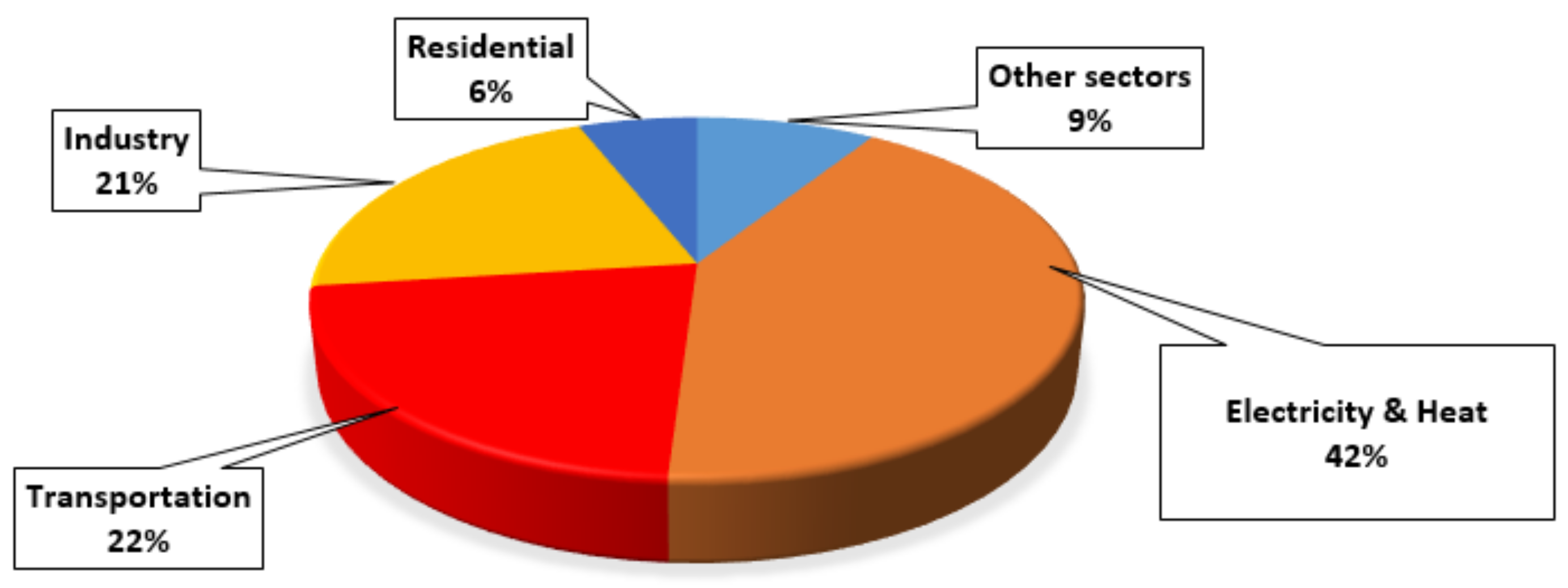
:1. Introduction
- (i)
- Charging standards as defined by the Society of the Automotive Engineers (SAE);
- (ii)
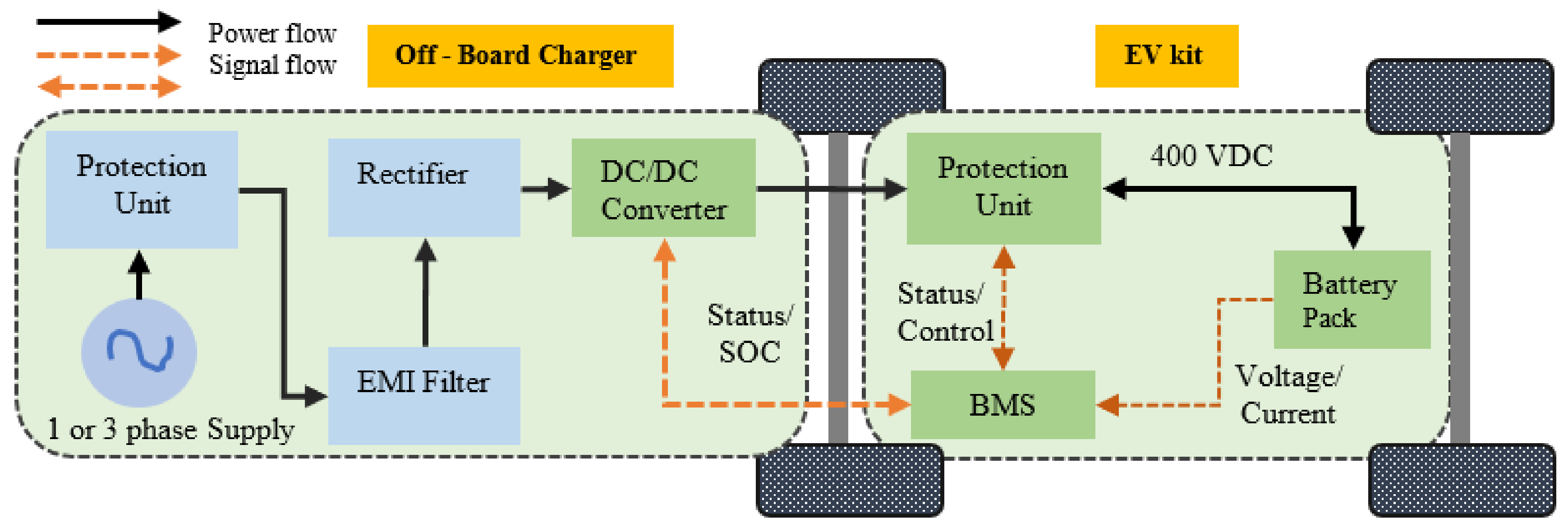
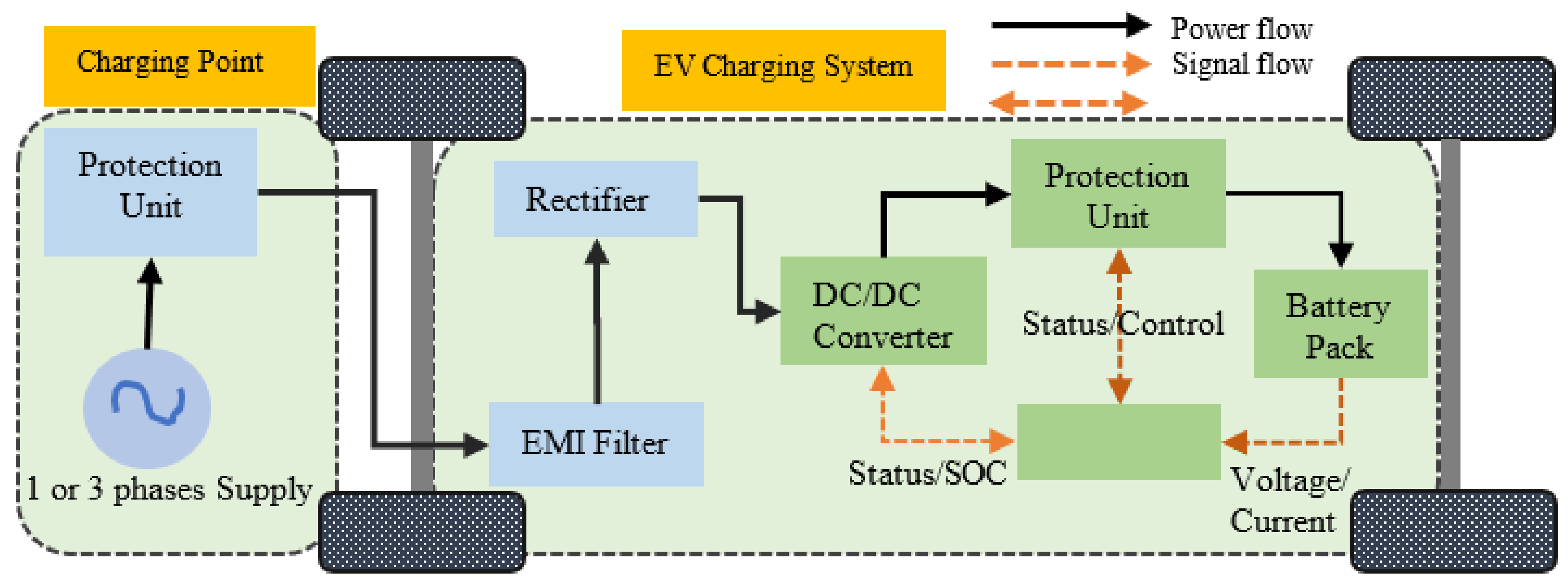
- EV charging systems such as on-board and off-board chargers, and
- (iii)
- Optimization techniques for sizing and placement of EV charging stations under different objectives and constraints.
2. Vehicle Technology
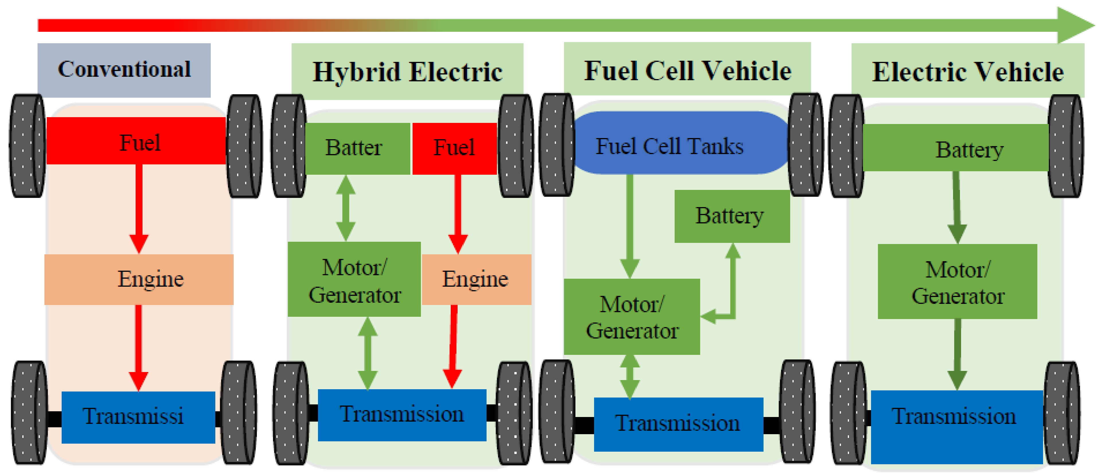
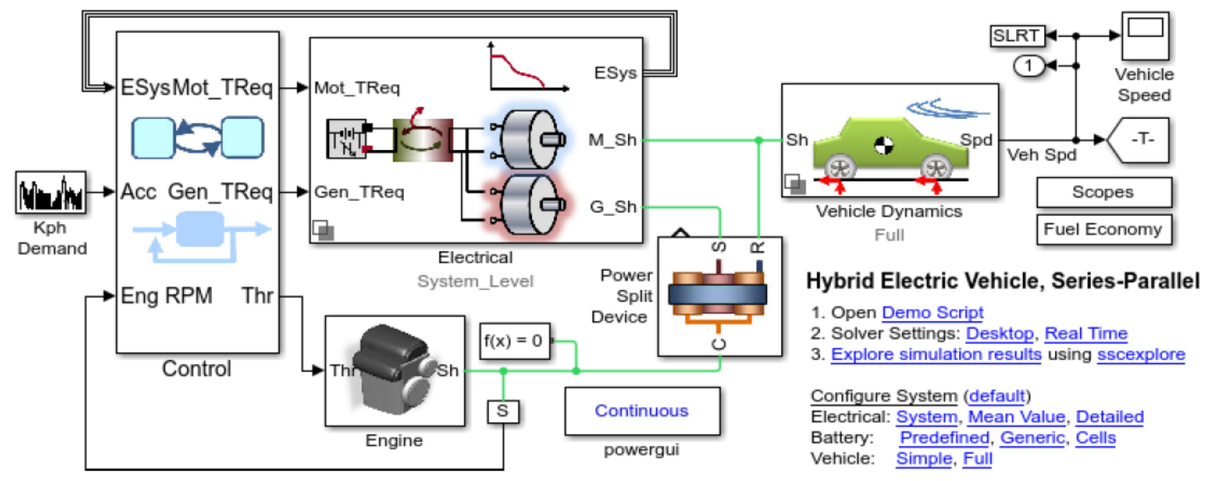
2.1. Hybrid Electric Vehicle
- (i)
- Improved fuel efficiency and performance.
- (ii)
- Lower fuel consumption costs.
- (iii)
- Reduce CO2 emission.
- (iv)
- Recovery of some energy via regenerative braking.
- (v)
- Use of an existing fuel station.
- (vi)
- The disadvantage is a higher initial cost due to the battery.
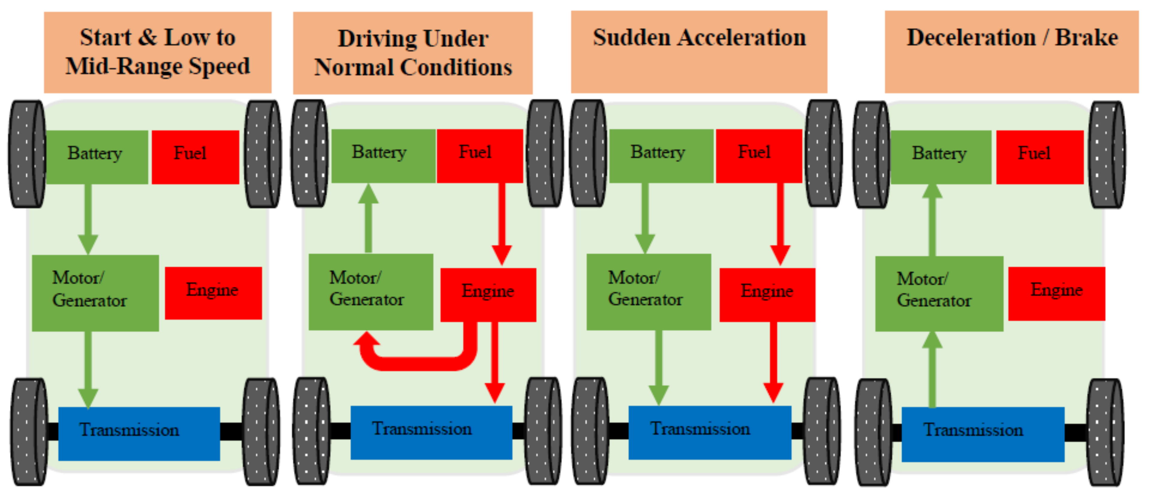
- (i)
- Start and Low to Mid-range Speeds: During low to mid-range speeds or at the vehicle’s starting, the engine stops, and the vehicle is propelled by the motor alone.
- (ii)
- Driving Under Normal Conditions: The power split device sends some power to run the generator and the rest of the power to drive the wheels directly. If there is excessive power, then it’s used to charge the battery.
- (iii)
- Sudden Acceleration: Both the battery and engine provide power during sudden acceleration.
- (iv)
- Deceleration: The regenerative braking system converts the kinetic energy into electrical energy that is stored in the high-performance battery.
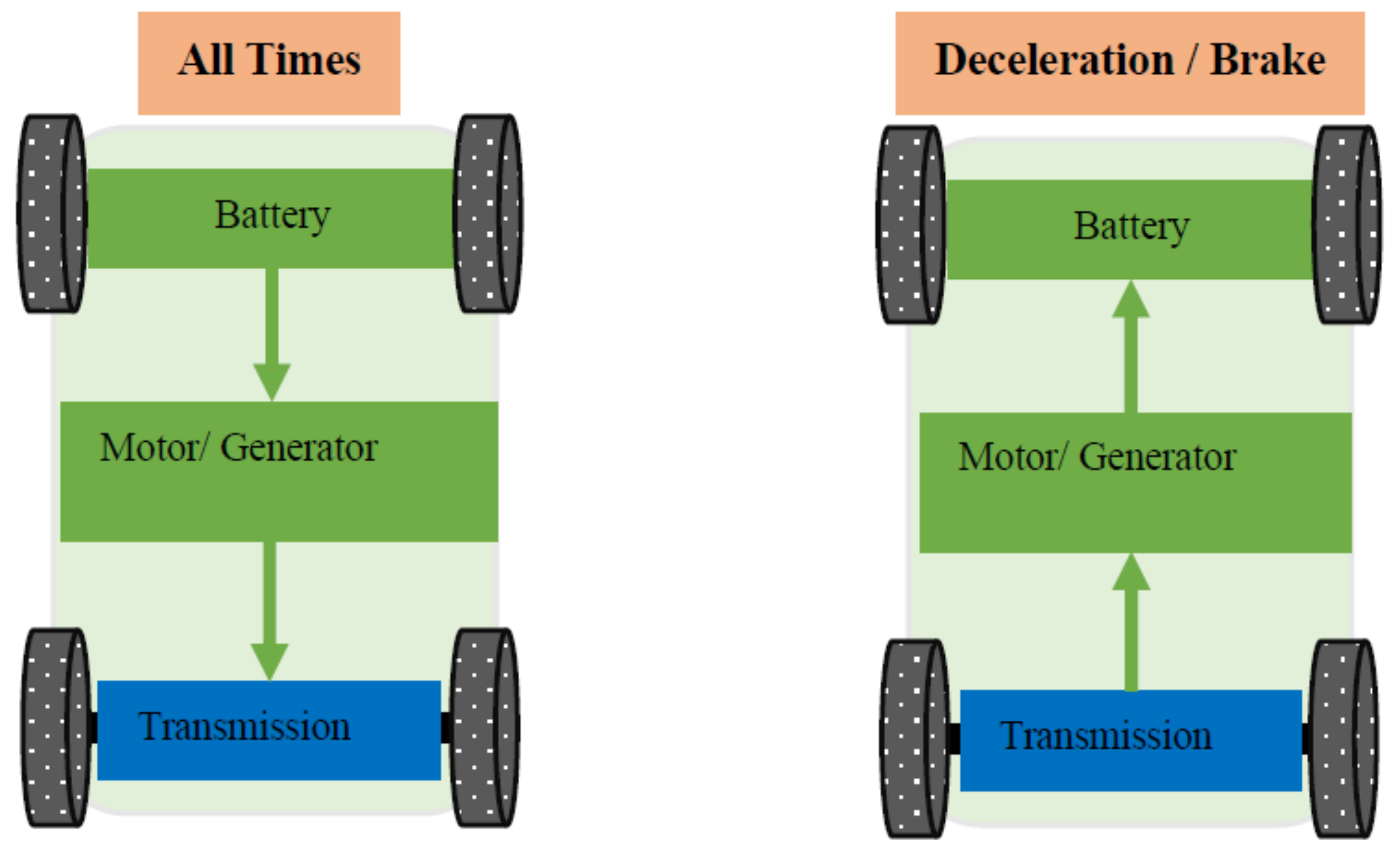
2.2. Electric Vehicle (EV)
- (i)
- All times: Whenever the vehicle needs to move, the battery propels the vehicle.
- (ii)
- Deceleration or Braking: When the vehicle decelerates or brakes, the vehicle recaptures the kinetic energy into the battery using regenerative technology.
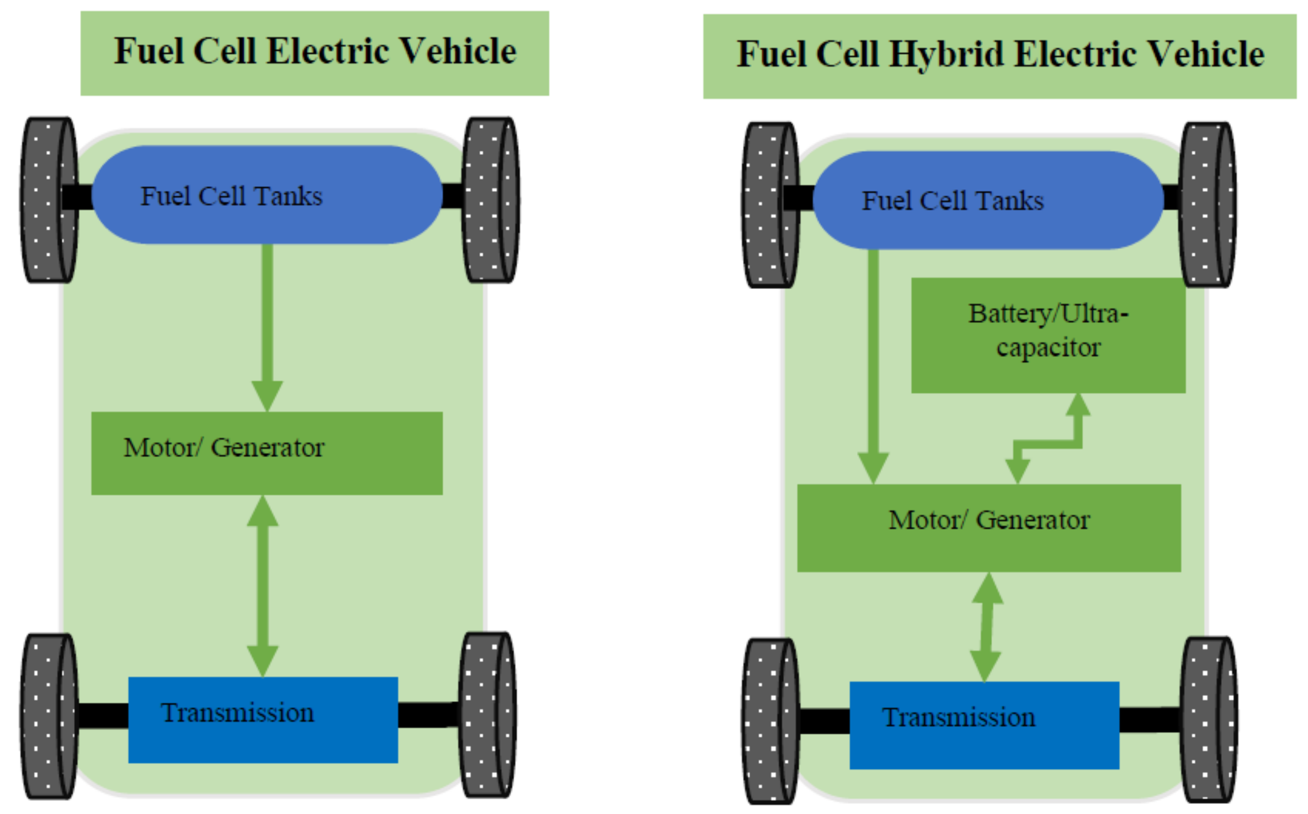
2.3. Fuel Cell Electric Vehicle (FCEV)
- (i)
- Fuel Cell Electric Vehicle.
- (ii)
- Fuel Cell Hybrid Electric Vehicle (FCHEV).
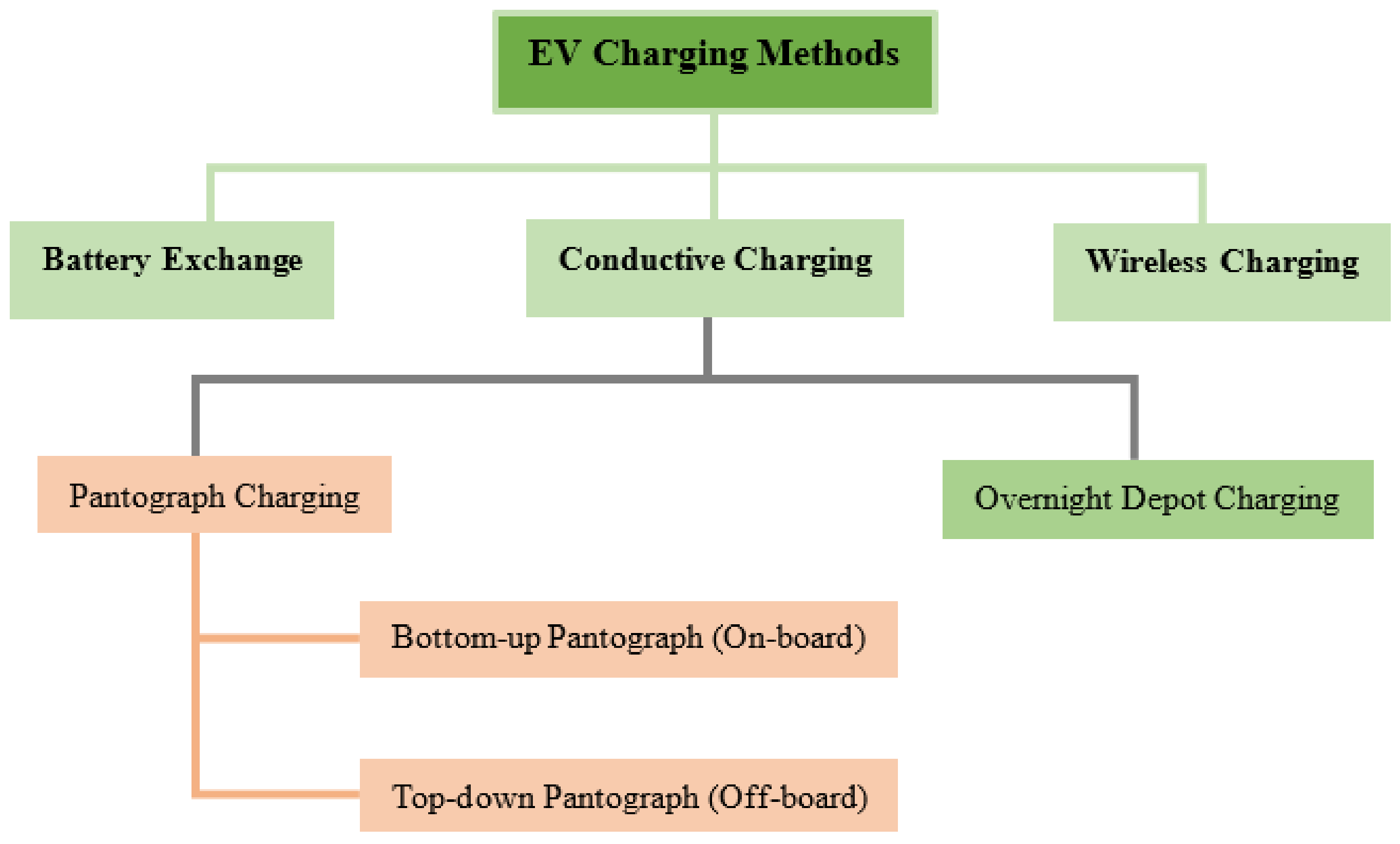
3. EV Charging Methods
3.1. Battery Swap Station (BSS)
3.2. Wireless Power Transfer (WPT)
3.3. Conductive Charging (CC)
- (i)
- Top-down Pantograph: The charging setup is mounted on the roof of the bus stop therefore it is commonly known as an off-board top-down pantograph. This method provides high power direct current which is already demonstrated in Singapore, Germany, and the U.S. [49].
- (ii)
- Bottom-up Pantograph: This type of charging method is suitable for those applications where the charging equipment is already installed in the bus. This is also known as an on-board bottom-up pantograph [49].
4. Review of EV Charging Configurations, and Standards
4.1. EV Charging Configurations
4.2. EV Charging Standards
5. Optimization Techniques
5.1. Reliability
5.2. Total Loss
5.3. Maximize the Profit
6. Discussion
6.1. Energy Source
- Grid.
- WT/PV.
- Diesel Generator.
- Hydro.
- Thermal.
- EV Fleet (for V2G purpose).
- ESS.
6.2. Optimization Method and Objectives
- Mixed-integer linear programming.
- Mixed-integer programming.
- Second-order conic programming (Convex Optimization).
- Markov chain Monte Carlo simulation.
- Particle swarm optimization and Voronoi diagram.
- Simulated annealing approach.
- Quadratic programming.
- Standard linear programming with the root-mean-square objective function.
6.3. Services and Test System
- Vehicle to Grid.
- Grid to Vehicle.
- Parking lot to grid.
- Parking lot to Vehicle.
6.4. Future Research Recommendations
- The research on the application of BESS and bi-directional power transfer capability of EVs in a distribution system can reduce the global warming issue more resourcefully by providing green electricity to homes and offices. Also, the intermittency of PV can be reduced by integrating optimally sized BESS [80]. Also, the profit of the parking lot owner can be maximized by incorporating battery swap to provide added value to customers.
- The frequent charging/discharging can cause EV battery life degradation [81]. Therefore, the use of BESS as an energy storage backup and subsequent sale of electricity to the building instead of discharging the EV battery repeatedly will ultimately increase the battery lifespan.
- The proposed PEB charge scheduling algorithms [46] can be applied to the charging scheduling of private EVs and Electric Ferries where the arrival and departure schedules are known. The battery capacity optimization for a given route can also be evaluated to minimize the vehicle cost.
- Research should be carried out on coordinated charging because uncoordinated charging of EVs can cause a peak load on a distribution system. EVs could be a great solution to settle these complications. In general, most vehicles are parked during peak load time. Therefore, using the stored electricity from vehicle (battery) to grid (V2G), electrical peak load would be reduced.
- Conventional PSO algorithm use for the optimal sizing has some problems such as searching the optimal value, the particles are trapped into local minima, and the number of iterations taken is increased [82,83]; therefore, the research could be carried out on the local trapping issue’s solution and computational time enhancement for example by hybridizing it with other heuristic technique can resolve these problems.
- The existing literature considered eco-charging systems (consisting of PV, ESS, and the electrical grid). However, mixing the other renewable DGs such as wind energy and Biomass energy can make the ecosystem more robust and sustainable and can conquer the intermittency issue caused by PV and wind.
- Research could be carried out on the charging and discharging model with the regenerative braking system of PEBs, which can lead to a more precise SOC estimation of PEBs.
- The existing literature considered the energy trading among the entities (PV, ESS, building, grid, and PEBs) in the ecosystem. However, generating power in multiple depots by using renewable energy resources and performing the energy trading between them can reduce the overloading of the grid.
7. Conclusions and Recommendation
Author Contributions
Funding
Conflicts of Interest
References
- Giannakis, E.; Serghides, D.; Dimitriou, S.; Zittis, G. Land transport CO2 emissions and climate change: Evidence from Cyprus. Int. J. Sustain. Energy 2020, 39, 634–647. [Google Scholar] [CrossRef]
- Fu, Y.; Hu, C.; Yang, D. Conservative or Aggressive?—The dynamic adjustment of Fit-in Tariff policy for PV power generation in China. Front. Energy Res. 2021, 9, 141. [Google Scholar] [CrossRef]
- Dong, Y.; Coleman, M.; Miller, S.A. Greenhouse Gas Emissions from Air Conditioning and Refrigeration Service Expansion in Developing Countries. Annu. Rev. Environ. Resour. 2021, 46, 1–25. [Google Scholar] [CrossRef]
- Wörner, R.; Morozova, I.; Cao, D.; Schneider, D.; Neuburger, M.; Mayer, D.; Körner, C.; Kagerbauer, M.; Kostorz, N.; Blesl, M.; et al. Analysis and Prediction of Electromobility and Energy Supply by the Example of Stuttgart. World Electr. Veh. J. 2021, 12, 78. [Google Scholar] [CrossRef]
- Herrington, R. Mining our green future. Nat. Rev. Mater. 2021, 6, 456–458. [Google Scholar] [CrossRef]
- Nykvist, B.; Olsson, O. The feasibility of heavy battery electric trucks. Joule 2021, 5, 901–913. [Google Scholar] [CrossRef]
- Lander, L.; Kallitsis, E.; Hales, A.; Edge, J.S.; Korre, A.; Offer, G. Cost and carbon footprint reduction of electric vehicle lithium-ion batteries through efficient thermal management. Appl. Energy 2021, 289, 116737. [Google Scholar] [CrossRef]
- Gold, R. Status Report on Electrification Policy: Where to Next? Curr. Sustain./Renew. Energy Rep. 2021, 8, 114–122. [Google Scholar] [CrossRef]
- Fried, T.; Welle, B.; Avelleda, S. Steering a Green, Healthy, and Inclusive Recovery through Transport; World Resources Institute: Washington, DC, USA, 2021. [Google Scholar]
- Australian Energy Market Commission: 2020 Retail Energy Competation. Available online: https://www.aemc.gov.au/sites/default/files/documents/2020_retail_energy_competition_review_-_final_report.pdf (accessed on 23 July 2021).
- Molyneaux, L. Queensland Energy Storage Manufacturing Plan 2020; Centre for Policy Futures, The University of Queensland: Brisbane, Australia, 2021. [Google Scholar]
- Nasab, N.M.; Kilby, J.; Bakhtiaryfard, L. Case Study of a Hybrid Wind and Tidal Turbines System with a Microgrid for Power Supply to a Remote Off-Grid Community in New Zealand. Energies 2021, 14, 3636. [Google Scholar]
- Natalini, D.; Bravo, G.; Newman, E. Fuel riots: Definition, evidence and policy implications for a new type of energy-related conflict. Energy Policy 2020, 147, 111885. [Google Scholar] [CrossRef]
- Erickson, L.E.; Brase, G. Electrification of Transportation. In Reducing Greenhouse Gas Emissions and Improving Air Quality; CRC Press: Boca Raton, FL, USA, 2019; pp. 39–50. [Google Scholar]
- Li, Z.; Khajepour, A.; Song, J. A comprehensive review of the key technologies for pure electric vehicles. Energy 2019, 182, 824–839. [Google Scholar] [CrossRef]
- Bozhkov, S. Structure of the Model of Hybrid Electric Vehicle Energy Efficiency. Trans. Motauto World 2021, 6, 76–79. [Google Scholar]
- Ehsani, M.; Singh, K.V.; Bansal, H.O.; Mehrjardi, R.T. State of the Art and Trends in Electric and Hybrid Electric Vehicles. Proc. IEEE 2021, 109, 967–984. [Google Scholar] [CrossRef]
- Mohith, K.; Patilkulkarni, S.; Kollaparti, N. Comparative Analysis of Different Control Techniques for Six-Phase PMSM as an Application to HEV. In Smart Sensors Measurements and Instrumentation; Springer: Berlin/Heidelberg, Germany, 2021; pp. 93–108. [Google Scholar]
- Van Harselaar, W.; Hofman, T.; Brouwer, M. Automated dynamic modeling of arbitrary hybrid and electric drivetrain topologies. IEEE Trans. Veh. Technol. 2018, 67, 6921–6934. [Google Scholar] [CrossRef]
- Kabalan, B.; Vinot, E.; Yuan, C.; Trigui, R.; Dumand, C.; El Hajji, T. Efficiency Improvement of a Series–Parallel Hybrid Electric Powertrain by Topology Modification. IEEE Trans. Veh. Technol. 2019, 68, 11523–11531. [Google Scholar] [CrossRef]
- Miller, S. Hybrid-Electric Vehicle Model in Simulink. 2014. Available online: https://au.mathworks.com/matlabcentral/fileexchange/28441-hybrid-electric-vehicle-model-in-simulink (accessed on 28 July 2021).
- Khodaparastan, M.; Mohamed, A.A.; Brandauer, W. Recuperation of regenerative braking energy in electric rail transit systems. IEEE Trans. Intell. Transp. Syst. 2019, 20, 2831–2847. [Google Scholar] [CrossRef] [Green Version]
- Xu, W.; Chen, H.; Zhao, H.; Ren, B. Torque optimization control for electric vehicles with four in-wheel motors equipped with regenerative braking system. Mechatronics 2019, 57, 95–108. [Google Scholar] [CrossRef]
- Liu, Y.; Gao, J.; Qin, D.; Zhang, Y.; Lei, Z. Rule-corrected energy management strategy for hybrid electric vehicles based on operation-mode prediction. J. Clean. Prod. 2018, 188, 796–806. [Google Scholar] [CrossRef]
- Arif, S.M.; Lie, T.T.; Seet, B.C. A Novel Simulation Model for analyzing the State of Charge of Electric Vehicle. In Proceedings of the IEEE PES, Innovative Smart Grid Technologies Asia, Singapore, 22–25 May 2018; pp. 1–5. [Google Scholar]
- Das, H.S.; Tan, C.W.; Yatim, A. Fuel cell hybrid electric vehicles: A review on power conditioning units and topologies. Renew. Sustain. Energy Rev. 2017, 76, 268–291. [Google Scholar] [CrossRef]
- Zhou, Y.; Huang, L.; Sun, X.; Li, L.; Lian, J. A Long-term Energy Management Strategy for Fuel Cell Electric Vehicles Using Reinforcement Learning. Fuel Cells 2020, 20, 753–761. [Google Scholar] [CrossRef]
- Bendjedia, B.; Rizoug, N.; Boukhnifer, M.; Bouchafaa, F.; Benbouzid, M. Influence of secondary source technologies and energy management strategies on Energy Storage System sizing for fuel cell electric vehicles. Int. J. Hydrogen Energy 2018, 43, 11614–11628. [Google Scholar] [CrossRef]
- Ahmad, A.; Khan, Z.A.; Alam, M.S.; Khateeb, S. A Review of the Electric Vehicle Charging Techniques, Standards, Progression and Evolution of EV Technologies in Germany. Smart Sci. 2017, 6, 36–53. [Google Scholar] [CrossRef]
- Gschwendtner, C.; Sinsel, S.R.; Stephan, A. Vehicle-to-X (V2X) implementation: An overview of predominate trial configurations and technical, social and regulatory challenges. Renew. Sustain. Energy Rev. 2021, 145, 110977. [Google Scholar] [CrossRef]
- Brenna, M.; Foiadelli, F.; Zaninelli, D.; Graditi, G.; Di Somma, M. The integration of electric vehicles in smart distribution grids with other distributed resources. In Distributed Energy Resources in Local Integrated Energy Systems; Elsevier: Amsterdam, The Netherlands, 2021; pp. 315–345. [Google Scholar]
- Erdinç, O.; Taşcıkaraoǧlu, A.; Paterakis, N.G.; Dursun, I.; Sinim, M.C.; Catalão, J.P. Comprehensive optimization model for sizing and siting of DG units, EV charging stations, and energy storage systems. IEEE Trans. Smart Grid 2017, 9, 3871–3882. [Google Scholar] [CrossRef]
- Li, T.; Zhang, J.; Zhang, Y.; Jiang, L.; Li, B.; Yan, D.; Ma, C. An optimal design and analysis of a hybrid power charging station for electric vehicles considering uncertainties. In Proceedings of the IECON 2018—44th Annual Conference of the IEEE Industrial Electronics Society, Washington, DC, USA, 21–23 October 2018; pp. 5147–5152. [Google Scholar]
- Sanguesa, J.A.; Torres-Sanz, V.; Garrido, P.; Martinez, F.J.; Marquez-Barja, J.M. A Review on Electric Vehicles: Technologies and Challenges. Smart Cities 2021, 4, 372–404. [Google Scholar] [CrossRef]
- Chowdhury, S.R. A Three-Phase Overlapping Winding Based Wireless Charging System for Transportation Applications; University of Akron: Akron, OH, USA, 2021. [Google Scholar]
- Patil, D.; McDonough, M.K.; Miller, J.M.; Fahimi, B.; Balsara, P.T. Wireless Power Transfer for Vehicular Applications: Overview and Challenges. IEEE Trans. Transp. Electrif. 2018, 4, 3–37. [Google Scholar] [CrossRef]
- Negarestani, S.; Fotuhi-Firuzabad, M.; Rastegar, M.; Rajabi-Ghahnavieh, A. Optimal sizing of storage system in a fast charging station for plug-in hybrid electric vehicles. IEEE Trans. Transp. Electrif. 2016, 2, 443–453. [Google Scholar] [CrossRef]
- Yoldaş, Y.; Önen, A.; Muyeen, S.M.; Vasilakos, A.V.; Alan, İ. Enhancing smart grid with microgrids: Challenges and opportunities. Renew. Sustain. Energy Rev. 2017, 72, 205–214. [Google Scholar] [CrossRef]
- Dharmakeerthi, C.H.; Mithulananthan, N.; Saha, T.K. Impact of electric vehicle fast charging on power system voltage stability. Int. J. Electr. Power Energy Syst. 2014, 57, 241–249. [Google Scholar] [CrossRef]
- Habib, S.; Khan, M.M.; Abbas, F.; Sang, L.; Shahid, M.U.; Tang, H. A Comprehensive Study of Implemented International Standards, Technical Challenges, Impacts and Prospects for Electric Vehicles. IEEE Access 2018, 6, 3866–13890. [Google Scholar] [CrossRef]
- Yang, Y.; Zhang, W.; Niu, L.; Jiang, J. Coordinated charging strategy for electric taxis in temporal and spatial scale. Energies 2015, 8, 1256–1272. [Google Scholar] [CrossRef] [Green Version]
- Dai, Q.; Cai, T.; Duan, S.; Zhang, W.; Zhao, J. A smart energy management system for electric city bus battery swap station. In Proceedings of the 2014 IEEE Conference and Expo Transportation Electrification Asia-Pacific (ITEC Asia-Pacific), Beijing, China, 31 August–3 September 2014; pp. 1–4. [Google Scholar]
- Martínez-Lao, J.; Montoya, F.G.; Montoya, M.G.; Manzano-Agugliaro, F. Electric vehicles in Spain: An overview of charging systems. Renew. Sustain. Energy Rev. 2017, 77, 970–983. [Google Scholar] [CrossRef]
- Electric Bus Arrive on Time: Marketplace, Economic, Technology, Environmental and Policy Perspectives for Fully Electric Buses in the EU. November 2018. Available online: https://www.transportenvironment.org/sites/te/files/publications/Electric%20buses%20arrive%20on%20time.pdf (accessed on 28 July 2021).
- Yilmaz, M.; Krein, P.T. Review of the Impact of Vehicle-to-Grid Technologies on Distribution Systems and Utility Interfaces. IEEE Trans. Power Electron. 2013, 28, 5673–5689. [Google Scholar] [CrossRef]
- Arif, S.M.; Lie, T.T.; Seet, B.C.; Ahsan, S.M.; Khan, H.A. Plug-In Electric Bus Depot Charging with PV and ESS and Their Impact on LV Feeder. Energies 2020, 13, 2139. [Google Scholar] [CrossRef]
- Arif, S.M.; Lie, T.T.; Seet, B.C.; Ayyadi, S. A novel and cost-efficient energy management system for plug-in electric bus charging depot owners. Electr. Power Syst. Res. 2021, 199, 107413. [Google Scholar] [CrossRef]
- Meishner, F.; Satvat, B.; Sauer, D.U. Battery electric buses in european cities: Economic comparison of different technological concepts based on actual demonstrations. In Proceedings of the 2017 IEEE Vehicle Power and Propulsion Conference (VPPC), Belfort, France, 11–14 December 2017; pp. 1–6. [Google Scholar]
- Carrilero, I.; González, M.; Anseán, D.; Viera, J.C.; Chacón, J.; Pereirinha, P.G. Redesigning European Public Transport: Impact of New Battery Technologies in the Design of Electric Bus Fleets. Transp. Res. Procedia 2018, 33, 195–202. [Google Scholar] [CrossRef]
- Pearre, N.S.; Kempton, W.; Guensler, R.L.; Elango, V.V. Electric vehicles: How much range is required for a day’s driving? Transp. Res. Part C Emerg. Technol. 2011, 19, 1171–1184. [Google Scholar] [CrossRef]
- Mwasilu, F.; Justo, J.J.; Kim, E.-K.; Do, T.D.; Jung, J.-W. Electric vehicles and smart grid interaction: A review on vehicle to grid and renewable energy sources integration. Renew. Sustain. Energy Rev. 2014, 34, 501–516. [Google Scholar] [CrossRef]
- Lenka, R.K.; Panda, A.K.; Dash, A.R.; Venkataramana, N.N.; Tiwary, N. Reactive Power Compensation using Vehicle-to-Grid enabled Bidirectional Off-Board EV Battery Charger. In Proceedings of the 2021 1st International Conference on Power Electronics and Energy (ICPEE), Bhubaneswar, India, 2–3 January 2021; pp. 1–6. [Google Scholar]
- Foqha, T.; Omar, M.A. Electric Vehicle Charging Infrastructures, Chargers Levels and Configurations; Academia: 2021; pp. 1–14. Available online: https://www.academia.edu/46518775/Electric_Vehicle_charging_infrastructures_chargers_levels_and_configurations (accessed on 1 August 2021).
- Xue, F.; Gwee, E. Electric vehicle development in singapore and technical considerations for charging infrastructure. Energy Procedia 2017, 143, 3–14. [Google Scholar] [CrossRef]
- Mangunkusumo, K.G.H.; Munir, B.S.; Hartono, J.; Kusuma, A.A.; Jintaka, D.R.; Ridwan, M. Impact of Plug In Electric Vehicle on Uniformly Distributed System Model. In Proceedings of the 2019 International Conference on Technologies and Policies in Electric Power & Energy, Yogyakarta, Indonesia, 21–22 October 2019; pp. 1–5. [Google Scholar]
- Das, H.; Rahman, M.; Li, S.; Tan, C. Electric vehicles standards, charging infrastructure, and impact on grid integration: A technological review. Renew. Sustain. Energy Rev. 2020, 120, 109618. [Google Scholar] [CrossRef]
- Ayyadi, S.; Bilil, H.; Maaroufi, M. Optimal charging of Electric Vehicles in residential area. Sustain. Energy Grids Netw. 2019, 19, 100240. [Google Scholar] [CrossRef]
- Fernandez, L.P.; Roman, T.G.S.; Cossent, R.; Domingo, C.M.; Frias, P. Assessment of the Impact of Plug-in Electric Vehicles on Distribution Networks. IEEE Trans. Power Syst. 2011, 26, 206–213. [Google Scholar] [CrossRef]
- Farzin, H.; Fotuhi-Firuzabad, M.; Moeini-Aghtaie, M. Reliability studies of modern distribution systems integrated with renewable generation and parking lots. IEEE Trans. Sustain. Energy 2017, 8, 431–440. [Google Scholar] [CrossRef]
- Wang, S.; Bi, S.; Zhang, Y.J.; Huang, J. Electrical Vehicle Charging Station Profit Maximization: Admission, Pricing, and Online Scheduling. IEEE Trans. Sustain. Energy 2018, 9, 1722–1731. [Google Scholar] [CrossRef] [Green Version]
- Ayyadi, S.; Maaroufi, M. Diffusion models for predicting electric vehicles market in Morocco. In Proceedings of the 2018 International Conference and Exposition on Electrical And Power Engineering (EPE), Iasi, Romania, 18–19 October 2018; pp. 46–51. [Google Scholar]
- Ayyadi, S.; Maaroufi, M. Optimal framework to maximize the workplace charging station owner profit while compensating electric vehicles users. Math. Probl. Eng. 2020, 2020, 7086032. [Google Scholar] [CrossRef]
- Fazelpour, F.; Vafaeipour, M.; Rahbari, O.; Rosen, M.A. Intelligent optimization to integrate a plug-in hybrid electric vehicle smart parking lot with renewable energy resources and enhance grid characteristics. Energy Convers. Manag. 2014, 77, 250–261. [Google Scholar] [CrossRef]
- Su, C.-L.; Leou, R.-C.; Yang, J.-C. Optimal Electric Vehicle Charging Stations Placement in Distribution Systems. In Proceedings of the IEEE IECON 2013, Vienna, Austria, 10–13 November 2013; pp. 2121–2126. [Google Scholar]
- Yan, X.; Duan, C.; Chen, X.; Duan, Z. Planning of Electric Vehicle Charging Station Based on Hierarchic Genetic Algorithm. In Proceedings of the ITEC Asia-Pacific, Beijing, China, 31 August–3 September 2014; pp. 1–5. [Google Scholar]
- He, J.; Zhou, B.; Feng, C.; Jiao, H.; Liu, J. Electric Vehicle Charging Station Planning Based on Multiple-Population Hybrid Genetic Algorithm. In Proceedings of the 2012 International Conference on Control Engineering and Communication Technology, Shenyang, China, 7–9 December 2012; pp. 403–406. [Google Scholar]
- Kirkpatrick, S.; Gelatt, C.D.; Vecchi, M.P. Optimization by Simulated Annealing. Science 1983, 220, 671–680. [Google Scholar] [CrossRef] [PubMed]
- Wang, Z.; Huang, B.; Xu, Y. Optimization of Series Hybrid Electric Vehicle Operational Parameters By Simulated Annealing Algorithm. In Proceedings of the IEEE International Conference Control and Automation, Guangzhou, China, 30 May–1 June 2007; pp. 1536–1541. [Google Scholar]
- Sousa, T.; Morais, H.; Vale, Z.; Faria, P.; Soares, J. Intelligent Energy Resource Management Considering Vehicle-to-Grid: A Simulated Annealing Approach. IEEE Trans. Smart Grid 2012, 3, 535–542. [Google Scholar] [CrossRef]
- Shafie-Khah, M.; Siano, P.; Fitiwi, D.Z.; Mahmoudi, N.; Catalao, J.P.S. An Innovative Two-Level Model for Electric Vehicle Parking Lots in Distribution Systems With Renewable Energy. IEEE Trans. Smart Grid 2018, 9, 1506–1520. [Google Scholar] [CrossRef]
- Awad, A.S.; Shaaban, M.F.; El-Fouly, T.H.; El-Saadany, E.F.; Salama, M.M. Optimal Resource Allocation and Charging Prices for Benefit Maximization in Smart PEV-Parking Lots. IEEE Trans. Sustain. Energy 2017, 8, 906–915. [Google Scholar] [CrossRef]
- Zhang, H.; Hu, Z.; Xu, Z.; Song, Y. An integrated planning framework for different types of PEV charging facilities in urban area. IEEE Trans. Smart Grid 2016, 7, 2273–2284. [Google Scholar] [CrossRef]
- Khodayar, M.E.; Wu, L.; Shahidehpour, M. Hourly Coordination of Electric Vehicle Operation and Volatile Wind Power Generation in SCUC. IEEE Trans. Smart Grid 2012, 3, 1271–1279. [Google Scholar] [CrossRef]
- Clement-Nyns, K.; Haesen, E.; Driesen, J. The impact of charging plug-in hybrid electric vehicles on a residential distribution grid. IEEE Trans. Power Syst. 2010, 25, 371–380. [Google Scholar] [CrossRef] [Green Version]
- Zheng, Y.; Shao, Z.; Jian, L. The peak load shaving assessment of developing a user-oriented vehicle-to-grid scheme with multiple operation modes: The case study of Shenzhen, China. Sustain. Cities Soc. 2021, 67, 102744. [Google Scholar] [CrossRef]
- Igualada, L.; Corchero, C.; Cruz-Zambrano, M.; Heredia, F.J. Optimal Energy Management for a Residential Microgrid Including a Vehicle-to-Grid System. IEEE Trans. Smart Grid 2014, 5, 2163–2172. [Google Scholar] [CrossRef] [Green Version]
- Ahsan, S.M.; Khan, H.A.; Hassan, N.-u.; Arif, S.M.; Lie, T.-T. Optimized power dispatch for solar photovoltaic-storage system with multiple buildings in bilateral contracts. Appl. Energy 2020, 273, 115253. [Google Scholar] [CrossRef]
- Nguyen, H.N.; Zhang, C.; Mahmud, M.A. Optimal coordination of G2V and V2G to support power grids with high penetration of renewable energy. IEEE Trans. Transp. Electrif. 2015, 1, 188–195. [Google Scholar] [CrossRef]
- Nimalsiri, N.I.; Ratnam, E.L.; Mediwaththe, C.P.; Smith, D.B.; Halgamuge, S.K. Coordinated charging and discharging control of electric vehicles to manage supply voltages in distribution networks: Assessing the customer benefit. Appl. Energy 2021, 291, 116857. [Google Scholar] [CrossRef]
- Teng, J.-H.; Luan, S.-W.; Lee, D.-J.; Huang, Y.-Q. Optimal Charging/Discharging Scheduling of Battery Storage Systems for Distribution Systems Interconnected With Sizeable PV Generation Systems. IEEE Trans. Power Syst. 2013, 28, 1425–1433. [Google Scholar] [CrossRef]
- Xu, M.; Wu, T.; Tan, Z. Electric vehicle fleet size for carsharing services considering on-demand charging strategy and battery degradation. Transp. Res. Part C Emerg. Technol. 2021, 127, 103146. [Google Scholar] [CrossRef]
- Arif, S.M.; Hussain, A.; Lie, T.T.; Ahsan, S.M.; Khan, H.A. Analytical Hybrid Particle Swarm Optimization Algorithm for Optimal Siting and Sizing of Distributed Generation in Smart Grid. J. Mod. Power Syst. Clean Energy 2020, 8, 1221–1230. [Google Scholar] [CrossRef]
- Pierro, M.; Perez, R.; Perez, M.; Prina, M.G.; Moser, D.; Cornaro, C. Italian protocol for massive solar integration: From solar imbalance regulation to firm 24/365 solar generation. Renew. Energy 2021, 169, 425–436. [Google Scholar] [CrossRef]
- Afonso, J.L. Battery charging station for electric vehicles based on bipolar dc power grid with grid-to-vehicle, vehicle-to-grid and vehicle-to-vehicle operation modes. In Proceedings of the Sustainable Energy for Smart Cities: Second EAI International Conference, SESC 2020, Viana do Castelo, Portugal, 4 December 2020; Volume 375, p. 187. [Google Scholar]
- Alsharif, A.; Wei, T.C.; Ayop, R.; Lau, K.Y.; Bukar, A.L. A Review of the Smart Grid Communication Technologies in Contactless Charging with Vehicle to Grid Integration Technology. J. Integr. Adv. Eng. (JIAE) 2021, 1, 11–20. [Google Scholar] [CrossRef]


| Types | Advantages | Disadvantages | Reference | Year |
|---|---|---|---|---|
| BSS | Quick battery replaces (Fully charged) | More costly than ICE vehicle because of the monthly rent to BSS | [42] | 2014 |
| BSS extend the battery life by slow charging | The huge investment required for both equipment and batteries | [43] | 2017 | |
| BSS help utilities in balancing the demand and load by using the V2G facilities | Need a large stock of expensive batteries | [32] | 2017 | |
| Easy to integrate with the locally generated RESs. | Many areas needed to accommodate the batteries | [33] | 2018 | |
| Different EVs have different battery standards. | ||||
| WPT | EV recharge it safely and conveniently | Power transfer is generally weak | [44] | 2018 |
| No need for any standard connector | The range of 20 to 100 cm for efficient power transmission | |||
| No need for any standard Socket | The transmitter and the EV should be real-time and communication latency. | [36] | 2018 | |
| Recharge when the vehicle is in motion. | ||||
| CC | Provide multiple charging levels | Complex infrastructure | [37] | 2016 |
| Provide high efficiency | Restriction to the electricity grid | [38] | 2017 | |
| Coordinated V2G facility | Fast charging cause voltage instability in the distribution system | [39] | 2014 | |
| Reduce the grid loss | ||||
| maintain voltage level | Need a standard connector/charging level | [40] | 2018 | |
| prevent grid power overloading | Grid power overloading will cause due to uncoordinated charging | [41] | 2015 | |
| Active power support. | V2G operation reduces the lifetime of the battery. | [45] | 2013 |
| Standards | Phase | Level/Mode | Voltage (V) | Current (A) | Source |
|---|---|---|---|---|---|
| IEC62196 | Single | Mode 1 | 120 | 16 | AC |
| Single | Mode 2 | 240 | 32 | ||
| Single | Mode 3 | 250 | 32–250 | ||
| DC | Mode 4 | 600 | 400 | DC | |
| IEC61851 | Single | Mode 1 | 120 | 16 | AC |
| Single | Mode 2 | 240 | 80 | ||
| DC | Mode 4 | 200–450 | 80 | DC | |
| SAEJ1772 | Single | Level 1 | 120 | 16 | AC |
| Single | Level 2 | 240 | 32–80 | ||
| DC | Level 1 | 200–450 | 80 | DC | |
| DC | Level 2 | 200–450 | 200 |
| Ref. | Energy Source | Optimization Method | Optimization Objective | Contribution | Service | Test System | Remarks |
|---|---|---|---|---|---|---|---|
| [59] | Grid WT/PV Diesel Parking lot | Mixed Integer Linear programming (MILP) | Enhance reliability through a probability model to quantify available energy in the PL | Outage management scheme | V2G | NHTS IEEE-34-node Test System | The NHTS data used is not practical EV data. Did not consider DRSs and EV constraints CO2 emission generated due to the use of diesel generators |
| [32] | Grid PV/WT ESS/Parking lot | Second-order conic programming (Convex Optimization) | Minimize total loss and maximize penetration Multi-objective optimization | Solved mismatch issue between the production of DG unit and load consumption | G2V | Alibeykoy feeders Hamikoy feeders (Istanbul, Turkey) | The investment and maintenance costs of ESS are ignored Power sold to the grid, instead of the contracted building |
| [70] | Grid PV ESS Parking lot | Mixed Integer Linear programming (MILP) | Parking lot owner profit is maximized through a two-level problem model PLO profit maximization DSO cost minimization | Energy trading between upstream (Aggregator) and downstream (PL) | PL2G | IEEE-34-node Test System PL assumed 1000 parking spaces | Used real PV and WT data, but the EV arrival and departure times are not based on real data Only focus on the operational framework |
| [71] | PV ESS | Markov Chain Monte Carlo Simulation is used to generate A/D/S duration | Parking lot owner profit maximization | Annual profit maximization of PEV-PL by selling electricity to PEV | PL2EV | Implemented in an existing building in Toronto, Canada | EV arrival and departure times are not based on real data Only focused on the planning framework |
| [72] | Grid only | Particle Swarm Optimization (PSO) and Voronoi diagram | Minimize the annual cost of an entire PEV charging station for the PL owner | Sizing and sitting of Fast charging station | G2V | One Nissan Leaf is selected to represent the PEV population Implemented in an urban area in China | EV arrival and departure times are not based on real data |
| [37] | Grid ESS | Mixed Integer Linear Programming (MILP) | Minimize Station Energy Cost (SEC) and ESS storage cost | Sizing of ESS in a fast-charging station | G2V | UK daily traffic data | Only considered fixed electricity rate and not real-time electricity rate. The presence of ESS is thus not economical Potential constraints such as inverter, Grid, and vehicles are ignored |
| [69] | RES ESS PL | Simulated Annealing Approach (SA) | Minimize aggregator operation cost through SA approach | The SA approach has a lower execution time than (GAMS) and GAMS_N | V2G | IEEE-33 bus Test system with 66 generators, 32 Loads & 1000 Grid-able vehicles | The total cost of network simulation is higher than another deterministic approach, e.g., GAMS (General Algebraic Modelling System) and GAMS_N |
| [73] | Grid/Wind Hydro Thermal EV fleet | Mixed Integer Programming (MIP) | Minimize grid operation cost through proposed stochastic security constraints unit commitment model for PEV and Wind | Modeling of large-scale PEV integration as mobile distributed storage Modeling of load facilities and their impact on the power system. | V2G | IEEE-6-Bus power system Modified IEEE-118-bus system | Only used vehicle storage capability and not ESS as a storage device. Frequent charging and discharging degrade the battery lifespan |
| [74] | Grid only | Quadratic programming | Minimize the distribution power loss Maximize the main Grid load factor using the proposed coordinated charging | Lower power loss Lower voltage deviation by leveling the peak power | G2V | IEEE-34-node Test System | The proposed approach can prolong voltage control by PHEV reactive power control and Grid balancing |
| [76] | Grid Wind/PV EV | Mixed Integer Linear Programming (MILP) | Minimize economic cost related to energy exchange between grid and micro-grid | Allocation of the shiftable load during off-peak hours minimizes the overall cost | V2G | Household data from Spain | By introducing ESS, the critical, adjustable, and shiftable load can be managed efficiently and profit can be increased |
| [77] | Wind PV Generator | Standard linear programming with the root-mean-square objective function | Minimize power imbalance in the grid through coordinated EVs charging and discharging | The optimization problem can compute quickly and efficiently Optimization will repeatedly calculate to revise V2G/G2V output of vehicle to deal with the error in prediction | G2V/V2G | Wind data collected from Victoria state, Australia | The power imbalance issue can be resolved by using ESS more effectively A diesel generator is used to provide ancillary service, which contributes to CO2 emissions. |
Publisher’s Note: MDPI stays neutral with regard to jurisdictional claims in published maps and institutional affiliations. |
© 2021 by the authors. Licensee MDPI, Basel, Switzerland. This article is an open access article distributed under the terms and conditions of the Creative Commons Attribution (CC BY) license (https://creativecommons.org/licenses/by/4.0/).
Share and Cite
Arif, S.M.; Lie, T.T.; Seet, B.C.; Ayyadi, S.; Jensen, K. Review of Electric Vehicle Technologies, Charging Methods, Standards and Optimization Techniques. Electronics 2021, 10, 1910. https://doi.org/10.3390/electronics10161910
Arif SM, Lie TT, Seet BC, Ayyadi S, Jensen K. Review of Electric Vehicle Technologies, Charging Methods, Standards and Optimization Techniques. Electronics. 2021; 10(16):1910. https://doi.org/10.3390/electronics10161910
Chicago/Turabian StyleArif, Syed Muhammad, Tek Tjing Lie, Boon Chong Seet, Soumia Ayyadi, and Kristian Jensen. 2021. "Review of Electric Vehicle Technologies, Charging Methods, Standards and Optimization Techniques" Electronics 10, no. 16: 1910. https://doi.org/10.3390/electronics10161910