1. Introduction
Systems engineering currently relies almost exclusively on natural language in sentence structures to contractually convey the needs and wants of stakeholders to those who would design and develop a solution to meet those needs and wants. Requirements efforts, namely low quality requirements and requirements engineering, are the first potential mistakes of an engineering project whose effects manifest themselves later in the engineering effort as increased costs and schedule overruns [
1,
2,
3,
4]. Requirement expressions are historically overlooked when considering innovation in systems engineering [
5]. Many of the efforts to improve systems engineering and requirements engineering have omitted changing requirement media and focused exclusively on how to improve the textual expression of requirements:
Consider that Johnson and Day described several model types to establish a Discipline of Systems Engineering, but stopped short of offering said models as requirement expressions [
5,
6].
Bruel et al. adjudicated a number of media as they relate to formalism and systems engineering, but focused on the application of formalism to address precision regarding validation instead of offering those media as requirement expression media for systems engineering [
7].
Natural language requirement specification ambiguity has been addressed with patterns in the work of Tjong et al. [
8] and improved structure in that of Carson [
9]; however, neither suggest changing the medium itself.
Otherwise, media available to capture requirements are often dismissed with no rigor as shown in the INCOSE Guide for Writing Requirements, which acknowledges the shortcomings of natural language but arbitrarily claims it to be the “only universal means of expression that covers the huge variety of concepts needed” [
10]. This research challenges the media constraint within current systems engineering requirement practices based on a media agnostic definition of requirements which defines requirement expressions as “a means to capture an instance of a want or need of:
This media agnostic definition creates a foundation to reimagine the media through which requirements are expressed within systems engineering.
This research starts the conversation on alternate media opportunities for systems engineering requirement expressions by comparing the characteristics of natural language sentences, model diagrams, and engineering drawings as systems engineering requirement expressions. This comparison reveals the differences that would need to be potentially overcome to consider using diagrams and drawings to capture requirements in systems engineering. Previous research has explored the representation of natural language requirements as models. For a system modeled in accordance with Wymore’s methodology [
11], it has been shown that the system requirements can be represented as SysML diagrams, although that work did not specifically address stakeholder requirements [
12]. In software engineering, research has explored the automated transformation of textual requirements into object-oriented models, which may in turn be expressed in object-oriented modeling languages such as the Unified Modeling Language (UML) [
13]. The research described in this paper goes beyond previous research in that: (1) it collects fundamental characteristics for requirement expressions for natural language sentences, model diagrams, and engineering drawings; (2) it compares these characteristic lists to identify differences; and (3) it proposes characteristics that apply to any potential media used to capture requirements. These results provide a basis for the use of different media to capture requirements within systems engineering.
Requirements are a form of information. The concept of requirements, requirement expressions, and sets of requirements expressions exist in multiple engineering disciplines [
5]. This research uses the term
requirement for the abstract need or want [
14]. The definition for requirement expression is adapted from the work of Ryan and Wheatcraft, who claim “a requirement statement is the result of a formal transformation of one or more needs into an agreed-to obligation for an entity to perform some function or possess some quality (within specified constraints)” [
15]. Ryan and Wheatcraft use the term
requirement statement, which carries the connotation of sentences, whereas this research uses the term
requirement expression to allow for multiple media options, such as model diagrams and engineering drawings, since those media meet the definition criteria. Requirements can then be expressed as requirement sentences, model diagrams, engineering drawings, and other media as illustrated in
Figure 1. The media considered in this paper are requirement sentences, model diagrams, and engineering drawings, and do not represent all potential media available for requirement expressions.
This paper is organized as follows:
Section 2: describes the research methodology including the sources used in the implementation of the methodology and validation of the methodology;
Section 3: illustrates instances of the methodology as implemented for both diagrams and engineering drawings and presents the outcomes of the analysis in tabular form;
Section 4: analyzes and interprets differences in the requirement expression characteristic analysis results between requirement sentences, diagrams, and engineering drawings;
Section 5: summarizes the key findings of the research, including limitations, and identifies areas for further research.
2. Materials and Methods
To gain broader insight into requirement expression characteristics, multiple engineering disciplines were explored in this research. In addition to systems engineering, this research expands the scope to include software engineering, mechanical engineering and electrical engineering. These engineering disciplines were selected based on the availability and accessibility of the standards and their use of requirements media distinct from requirements sentences [
5]. These scoped disciplines also scope the media for requirement sentences (systems engineering), model diagrams (software engineering), and engineering drawings (mechanical and electrical engineering). The scope of this research serves as a starting position for theoretical foundations and its findings can be generalized to show how the characteristics or requirement expressions relate across various engineering disciplines.
2.1. Approach
The approach for this research has two phases. The first phase is a critical review of high-impact sources to identify characteristics of requirement media from the scoped engineering disciplines [
7,
16]. The critical review uses the INCOSE characteristics as themes to identify passages that address similar themes in respect to the scoped media. The critical review also sought passages that addressed characteristics that may not be aligned with the INCOSE characteristics. By using the INCOSE characteristics, this research applied a minimum characteristic set for the viability of a medium; therefore, the absence of additional characteristics does not negatively affect this research premise.
The second phase is a comparative analysis of the identified characteristics across the scoped media to determine the similarities and differences. A characteristic list is developed for each media based on the evidence of the critical review. Each media characteristic list is then compared to enable discussion and conclusions. This methodology supports the goal of this research to determine the viability of model diagrams and engineering drawings as viable for system requirements.
2.2. Validation
This research bases its validity on two primary qualitative research principles: authenticity of data and comparison objectivity [
17]. Poor data generate poor results and an improper comparison provides no insight between the objects of comparison. The quality and authenticity of the data is addressed using reputable sources. Objectivity is maintained by making a proper comparison [
17,
18].
Two items must be addressed to ensure a proper comparison of the requirement expression characteristics: (1) the characteristics must be adapted to this research; and (2) the comparison approach needs to be explained. Each characteristic, for each scoped media, is subsequently elaborated in the context of this research in subsequent sections. This research bases the characteristic comparison on the brief description of the INCOSE source and the literature review findings for the scoped disciplines. The comparison does not extrapolate beyond that available information.
A proper comparison would also be between similar amounts of information. In systems engineering, a system is represented as a set of requirement sentences, whereas in the other scoped disciplines, a system is represented with a model set or an engineering drawing set. From the perspective of model-based systems engineering (MBSE), model diagrams and engineering drawings, including digital CAD, are views or perspectives of the overall model of a system. “There is no such thing as non-model based engineering” [
19] since specifications are just verbal models, according to von Bertalanffy [
20]. If specifications are considered verbal models, then collections of requirement sentences from a specification would be equivalent to a model diagram or an engineering drawing. From the other perspective, a single model diagram or engineering drawing may need multiple requirement sentences when represented in natural language. This transformation continues into individual wants and needs being represented with a single requirement sentence in systems engineering or a component within a model diagram or an engineering drawing. These assertions have been aligned in
Table 1 for natural language sentences, models, and drawings. This alignment of information representation supports the effort of a proper comparison by ensuring that a similar amount of information is being considered.
2.3. Example
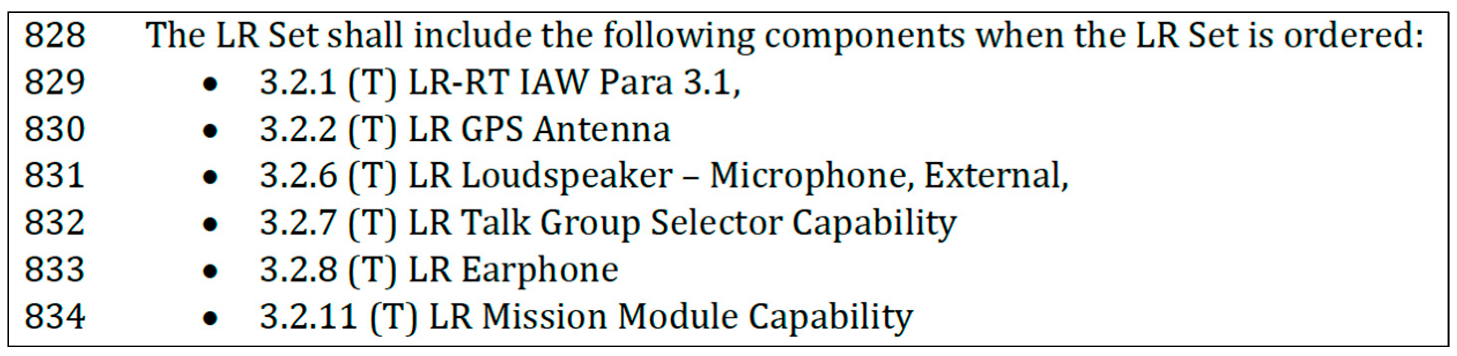
The following example of a requirement sentence and a potential model diagram are provided to illustrate the alignment of information between alternative media. The Leader Radio (LR) Performance Requirements Document (PRD) from 2019 provides a relatively straight forward requirement sentence that defines the components of an ordered, i.e., purchased, LR set. The LR PRD is a publicly released document seeking procurement of a two-channel radio system in handheld and mounted (M-LR) variants [
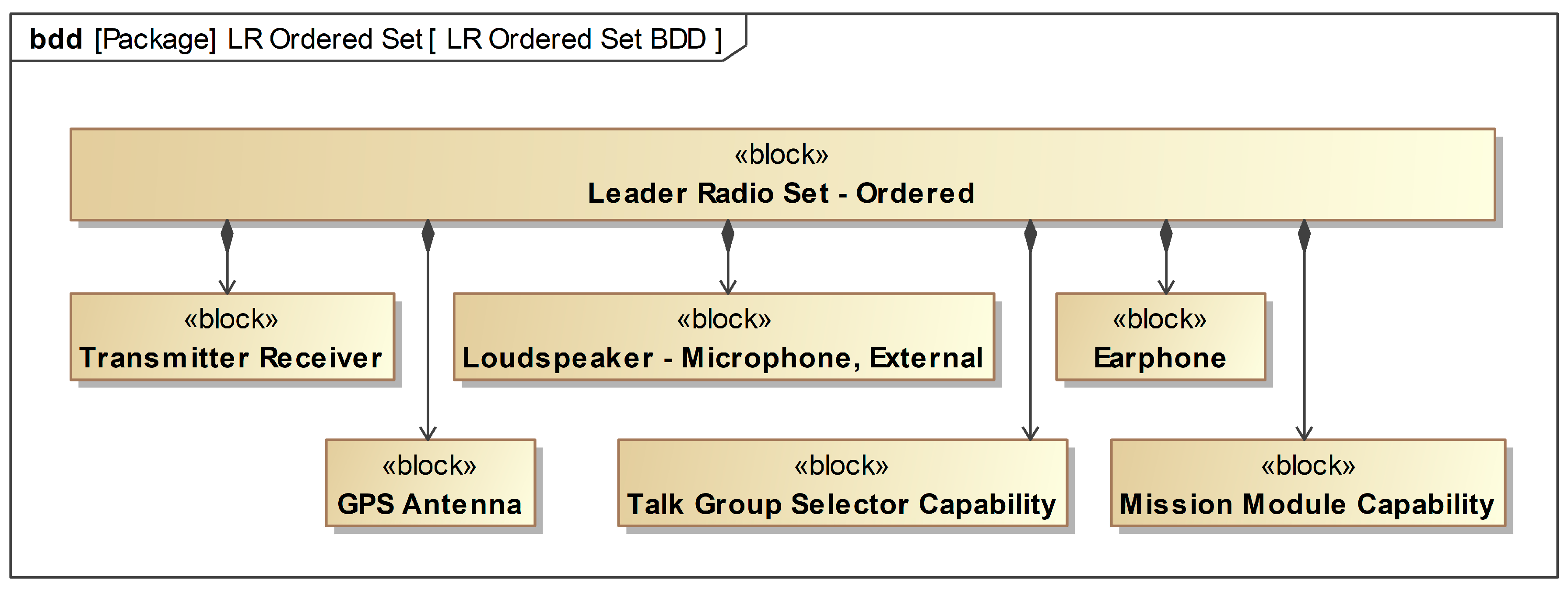
21]. The LR PRD includes several sections that establish a capability and component hierarchy using only requirement sentences. There are no alternate media offered to complement these hierarchies, even as supplemental, i.e., non-requirement expression, material in the LR PRD. This paper developed Figure 3 as a model diagram of the requirement sentence in
Figure 2.
Figure 3 presents a SysML block definition diagram that depicts the composition of the LR ordered set. Even without elaborating on the particulars of SysML notation, readers can infer the equivalent information content of both the textual and diagram representations of the LR ordered set. In the interest of brevity, no engineering drawing example was developed.
3. Results
This section provides the requirement expression characteristics for the scoped disciplines and media. Each media are given their own section that provides the characteristics and their basis. A final section consolidates the findings and provides brief observations to conclude the first phase of the methodology prior to the comparative analysis.
3.1. Requirement Sentence Characteristics in Systems Engineering
Within systems engineering, there are many sources of what makes a “good” requirement expression [
1,
2,
3,
4,
5] and how to avoid mistakes in requirements expression, all of which are offered for requirement sentences as the default media for expressing the requirements [
6]. The Institute of Electrical and Electronics Engineers’ (IEEE) source for requirements engineering is a standard shared with ISO and IEC—ISO/IEC/IEEE 29148 [
7]. A review of this high-impact source led to the recognition that the INCOSE Guide for Writing Requirements and ISO/IEC/IEEE 29148:2018 have identical characteristics for both individual requirement sentences and sets of requirement sentences [
8]. While there are many sources on the subject of requirement expressions in systems engineering and requirements engineering [
1,
2,
3,
4,
5,
9], this research used the characteristics found in the INCOSE Guide for Writing Requirements and ISO/IEC/IEEE 29148:2018 standards since there is an established precedent for scoping research to standards [
10].
The characteristics of individual requirement sentences and sets of requirement sentences are defined in both the INCOSE Guide for Writing Requirements and ISO/IEC/IEEE 29148:2018. Those lists and their definitions are captured in
Table 2 and
Table 3.
When utilizing natural language requirement sentences, each of the other scoped engineering disciplines used the same characteristics as systems engineering to characterize individual requirement sentences and sets of requirement sentences. Software engineering uses the same specification documentation to capture requirement sentences [
11].
3.2. Example—Requirement Sentence
Recall the leader radio (LR) example introduced in
Section 2.3 for illustration of the equivalence of characteristics of two alternative media for representing the LR ordered set.
Figure 1 is a requirement sentence that shows some of the INCOSE characteristics. The compilation of the ordered LR Set is “Unambiguous”, “Feasible”, and “Verifiable”. Without additional context, it cannot be stated with certainty that the requirement sentence is “Necessary”, “Appropriate”, “Complete”, “Singular”, “Correct”, or “Conforming”.
3.3. Model Characteristics in Software Engineering
UML is a widely accepted standard for modeling software. This research uses the UML user guide, which is a high-impact source that defines UML and the use of UML as the primary source regarding modeling in software engineering [
11]. While the INCOSE guide provided a specific list, the UML user guide provides insight into the characteristics of software models throughout its text with no specific list. The literature review did not identify a standard list of characteristics for model diagrams such as INCOSE has for system requirements. A critical review using the INCOSE characteristics as themes identified passages that addressed similar themes in respect to model diagrams. The critical review also looked for passages that addressed software model characteristics but may not be aligned with the INCOSE characteristics. No such passages were identified. By using the INCOSE characteristics, this research applied a minimum characteristic set for the viability of a medium; therefore, the absence of additional characteristics does not negatively affect this research premise.
These themes are captured and compared in
Table 4 and
Table 5 along with relevant passages to support the model characteristic. To illustrate an example, consider the sixth row in
Table 4 which cites the third principle of modeling offered in the UML user guide, “the best models are connected to reality”, a passage that directly cites the media and names a characteristic. The theme of realism is analogous to the INCOSE characteristic “feasible”. This process was repeated while reviewing the UML user guide for characteristics. The applicable text name of the characteristics is drawn directly from the cited text to maintain the integrity of the source for the upcoming comparison.
This literature review did not identify model characteristics to match the requirement characteristics of “Verifiable”, “Comprehensible”, and “Able to be Validated”. These differences in the model diagram characteristics and the requirement sentence characteristics are addressed in the comparative analysis in a subsequent section.
The UML guide cites the use of multiple models within software engineering [
11], which differs from MBSE, which utilizes a single model with model diagrams serving as perspectives of the single model [
12]. While this is a semantic difference, the UML guide’s references to models align with the MBSE concept of model diagrams; therefore, this information is applicable to the media.
3.4. Example—Model Diagram
Returning to the LR example introduced in
Section 2.3,
Figure 2 is a notional model diagram of the requirement sentence in
Figure 1.
Figure 2 is a SysML block definition diagram that shows the composition of the LR ordered set. SysML is an extension of UML [
13]. Using the UML user guide characteristics,
Figure 2 is “Unambiguous” and “Realistic”. As stated in
Section 3.3, the UML guide did not identify a model characteristic to match the requirement characteristic of “Verifiable”. The remaining characteristics must be assumed without additional context, which is a similar assessment to that in
Figure 1.
3.5. Drawing Characteristics in Electrical and Mechanical Engineering
Research into engineering drawing characteristics for electrical and mechanical engineering revealed that a logical representation was defined by the American National Standards Institute (ANSI)/IEEE 991—Logic Circuit Diagrams [
13] and physical representations were defined by the American Society of Mechanical Engineers (ASME) Y14.100—Engineering Drawing Practices [
14] and ASME Y14.24—Types and Applications of Engineering Drawings [
15]. ASME Y14.100 is a high-impact document that has been adopted by the Department of Defense since 1997 (per MIL-STD-100G [
16], MIL-DTL-31000 [
17], and MIL-STD 31000 [
18]). This research also used ANSI Y14.15—interconnecting diagrams [
19]—which is included for historical purposes as this source was used from its inception in 1966 through to its latest reaffirmation in 1988 until it was withdrawn in 1997 [
20].
ASME Y14.100 “establishes the essential requirements and reference documents applicable to the preparation and revision of engineering drawings”; however, most of the “requirements” it refers to are attributes of the drawings such as title and revision history. These are not the requirements applicable to this research. The primary benefit of ASME Y14.100 for this research is its further referred documents for more specific details on aspects of engineering drawings which include ASME Y14.24, IEEE 991, and, until 1997, ANSI Y14.15. The relationship between these documents shows that electrical and mechanical engineering adhere to the same characteristics despite the differences in the nature of the media, i.e., the inherent properties of the media.
It should be noted that ASME Y14.100 states that these characteristics of drawings are applicable to both digital data and drawings. ASME Y14.24 describes the use of tables to capture requirements such as common characteristics that are stated once while the differences are tabulated, and each item is attributed a part or identifying number (PIN). ASME Y14.24 also allows for the combination of drawing types provided the requirements are met for each. Very similarly to the model quality characteristics, the literature showed themes consistent with the INCOSE Guide for Writing Requirements, which are listed and compared in
Table 6 and
Table 7. For example, row one in
Table 6 shows the IEEE 991 claim that diagrams show necessary information which directly states the same characteristic as INCOSE. The second row of
Table 6 relates the engineering drawing characteristic of scale to the INCOSE appropriate characteristic as they are both used to ensure the representation of the requirement is sufficient and complete for its intended use. The second row of
Table 7 shows that ASME Y14.24 describes how a complete set of engineering drawings is compiled to ensure that development or production can occur.
This research did not identify engineering drawing characteristics to match the requirement characteristics of “Verifiable”, “Feasible”, and “Able to be validated”. These differences in the drawing characteristics and the requirement sentence characteristics are addressed in the subsequent section.
3.6. Observations on Requirement Expression Characteristics
The characteristics identified by this research for the scoped disciplines and media are consolidated for both individual characteristics (
Table 8) and set characteristics (
Table 9). The gathering, alignment, and comparison of characteristics of requirement sentences, model diagrams, and engineering drawings revealed a similarity among the scoped disciplines for what constitutes proper use of each of their respective media. Many of the characteristics used the same vocabulary to either state or describe the characteristic as necessary, complete, and singular. These concepts applied to both individual requirement expressions and sets of requirement expressions. The differences in the lists and alignments are the focus of the comparative analysis section which follows.
4. Discussion
This section addresses the comparative analysis phase of the methodology. The first phase identified similar characteristics between the scoped disciplines and their media. These similarities indicate that the scoped disciplines have similar intentions for their respective requirement expression media. The differences in the characteristic lists were omissions:
Model diagrams did not have an individual characteristic align with the INCOSE “Verifiable”;
Model diagrams did not have a set characteristic align with the INCOSE “Comprehensible” or “Able to be validated”;
Engineering drawings did not have an individual characteristic align with the INCOSE “Feasible” or “Verifiable”;
Engineering drawings did not have a set characteristic align with the INCOSE “Feasible” or “Able to be validated”.
The INCOSE characteristics that were omitted are similar for individual requirement expressions and requirement sets; therefore, they are addressed simultaneously based on the alignment in
Table 10. This table defines each characteristic for subsequent comparison.
4.1. Unambiguous and Comprehensible
Ambiguity continues to be a struggle in requirements engineering [
8,
22,
23]. Ambiguity is directly related to semantics and pragmatics which, along with context, guide the reader to the interpretation intended by the requirement developer, which is the toolmaker’s paradigm [
24]. These topics are researched in cognitive sciences; however, the applicability to systems engineering is that accountability is improved when ambiguity is reduced as it ensures that both parties understand what is expected from one another.
Different media inherently possess differing capabilities for providing context or, alternatively, reducing ambiguity. Sentences, when unburdened with arbitrary constraints, carry the most flexibility to communicate requirements anywhere on the spectrum of abstraction, from the conceptual to empirical [
24]. This is consistent with the INCOSE Guide for Writing Requirements which acknowledges that sentences are the most flexible and the most easily understood media [
8] and that flexibility covers a wide range of context; however, this research contends that the flexibility is created by a lack of inherent context in the media, i.e., a sentence provides no inherent context and is therefore more flexible. Conversely, model diagrams, to include formal logic, provide spatial context and relationships between their components which allow engineers and problem solvers to better understand what is being conveyed [
11,
22]. Since more context is preferable in communication [
24] and visual context reduces cognitive load [
25], higher-context-offering media are potentially preferable in communication. This implies that model diagrams are potentially preferable in communication to requirement sentences in that model diagrams are less ambiguous based on the level of context needed or wanted to be conveyed.
The model diagram literature omitted a set characteristic related to “Comprehensible”. Because each model diagram can represent multiple requirement sentences, the individual characteristics potentially address the same amount of information as a set of requirement sentences. Therefore, it may be inferred that the “Unambiguous” characteristic for a model applies to both model diagrams and model diagram sets. Additionally, if a model set can be characterized using the characteristics of its components, then it stands that if lower-level representations are “Unambiguous”, then the collective set is “Unambiguous”. These two concepts imply that the omission of “Comprehensible” from model diagram sets is covered by the individual characteristic for “Unambiguous” model diagrams.
4.2. Feasible
For requirement sentences, feasibility is ensured via the restraint of the requirement developer [
3,
26]. Engineering drawings do not carry a characteristic to match “Feasible” for individual or sets of drawings (
Table 8). Many of the engineering drawing types depict components ready for manufacture and are therefore bound to physical laws, which inherently provides feasibility [
27]. The level of abstraction of the information dictates which media can be used to represent it. That said, being able to draw a concept speaks to its feasibility. If a component or concept can be diagrammed or drawn, the ability of the concept to be realized as part of the solution is shown to be more feasible. Therefore, based on indirect evidence, engineering drawings provide a potentially positive benefit regarding the determination of feasibility for a requirement expression.
4.3. Verifiable and Able to Be Validated
The “Verifiable” requirement sentence characteristic ensures that the requirement can be realized at the level of abstraction described [
8]. For a requirement set, the “Able to be validated” characteristic ensures that the set achieves the goal of the originating stakeholder [
8]. Currently, requirement developers gather verification information from appropriate stakeholders, such as the test group, to ensure that requirement sentences are verifiable [
3,
25]. These concepts provide accountability within the requirement sentence.
This research did not identify any matching characteristics for model diagrams or engineering drawings. Requirement sentences, because of their flexibility to capture abstractions and the ambiguity tied to natural language [
24], are at risk of being unverifiable and therefore require a contingency to ensure the author accounts for verification. An example would be capability requirements that capture concepts from a concept of operations (CONOPS) document while deliberately maintaining an implementation agnostic position, as described in the INCOSE Systems Engineering Handbook [
28]. Model diagrams may be verified using various strategies. Model diagrams can enable objective verification strategies including executable models [
29,
30,
31]. Executable models can be used to capture and communicate requirement expressions among stakeholders and allow systems engineers to “forecast success in meeting the expectations of users and the acquirer, as well as to provide feedback to identify and correct performance deficiencies before implementation” [
32,
33,
34]. The concept of executing model diagrams indicates that verification and validation are important to the respective scoped disciplines. Verifying an engineering drawing can be a straightforward process of inspections or measurements of compliance of the component as produced to the drawing. This does not imply that all drawings are verifiable as it is possible to draw a component that cannot be realized. However, a proper drawing is complete with tolerances and the other characteristics are inherently more verifiable because of the empirical information provided [
35]. Overall, there is indirect evidence to support a claim that engineering drawings are more verifiable based on their visual representations.
The omission of the characteristics does not reduce that importance; however, it would indicate less concern with the scoped media representing information that is not “Verifiable” or “Able to be validated”. The omission would also conversely imply that requirements expressed as model diagrams inherently possess less uncertainty or ambiguity regarding verification and validation.
4.4. Returning to the Example
The leader radio (LR) example introduced in
Section 2.3 was assessed (
Section 3.2 and
Section 3.4) based on the findings of this research, which showed that there was no direct UML characterization for the “Verifiable” requirement sentence characteristic.
Figure 2, the SysML model diagram, shows an “Unambiguous” and “Realistic” composition for the LR ordered set.
Figure 2 is “Verifiable” based on the definition of the requirement sentence characteristic and illustrates the implication that model diagrams are inherently clearer concerning verification.
4.5. Observations on the Differences
It can be said that, fundamentally, the scoped disciplines have very similar although not identical characteristics for their requirement expression media. A set of unambiguous individual model diagrams would likely be “Comprehensible”; therefore, a specific set characteristic of “Comprehensible” could be interpreted as unnecessary. A set of feasible individual engineering drawings would likely be “Feasible”; therefore, a specific set characteristic of “Feasible” could be interpreted as unnecessary. Both model diagrams and engineering drawings have less ambiguity and uncertainty compared to natural language requirement sentences based on inherent context. Additionally, both model diagrams and engineering drawings as requirement expressions are inherently more feasible, verifiable, and able to be validated.
5. Conclusions
This paper conducted a critical review of high-impact sources to identify characteristics of requirement media from the scoped engineering disciplines of systems, electrical, and mechanical engineering. Characteristic lists were developed for engineering drawings using the INCOSE system requirement sentence characteristics as themes. Model diagrams shared a total of eight of the INCOSE characteristics for individual requirements, and engineering drawings shared a total of seven of the characteristics. These characteristic lists showed that the scoped disciplines characteristics correlate strongly to the fundamental characteristics for requirement sentences. The characteristics of requirement expressions are largely consistent across the disciplines of systems engineering, software engineering, electrical engineering, and mechanical engineering.
Neither model diagram nor engineering drawing characteristics included the “Verifiable” individual characteristic, and engineering drawing characteristics did not include the “Feasible” individual characteristic either. Neither model diagrams nor engineering drawings included the “Able to be validated” set characteristic. Model diagrams did not include the “Comprehensible” set characteristic, and engineering drawings did not include the “Feasible” set characteristic. The differences in the characteristic lists are attributable to the flexibility of natural language and the inherent context provided by model diagrams and engineering drawings. The more flexible the media are, the more characteristics are needed to ensure that the information is captured properly; therefore, additional characteristics are applied to the development of natural language requirement sentences.
Both model diagrams and engineering drawings have inherent context and therefore less ambiguity and uncertainty compared to natural language requirement sentences. Thus, model diagrams are inherently more comprehensible, verifiable, and able to be validated. Likewise, engineering drawings are inherently more feasible, verifiable, and able to be validated. This research has shown that model diagrams and engineering drawings are viable to be considered for use as requirement expressions in systems engineering based on their ability to capture information with the same characteristics typified by systems engineering.
6. Further Research
The viability of the scoped media does not provide the justification for their potential inclusion. Further research is needed to identify potential benefits that different media would provide in a system engineering context. This paper was limited to model diagrams and engineering drawings as potentially viable media for systems requirement expressions. Additionally, there is an opportunity to identify other media for inclusion. The inclusion of different media will create confusion and challenges on occasion both to potential readers and requirement developers. Hence, a media selection framework will need to be developed to choose the best media for a given requirements expression or set of requirements expressions in the requirements engineering process.
Author Contributions
Conceptualization, J.K. and L.D.T.; methodology, J.K.; validation, J.K.; formal analysis, J.K.; investigation, J.K.; writing—original draft preparation, J.K.; writing—review and editing, L.D.T. All authors have read and agreed to the published version of the manuscript.
Funding
This research received no external funding.
Data Availability Statement
No new data were created or analyzed in this study. Data sharing is not applicable to this article.
Conflicts of Interest
The authors declare no conflict of interest.
References
- Davis, A.M. Software Requirements: Objects, Functions, and States; PTR Prentice Hall: Englewood Cliffs, NJ, USA, 1993; ISBN 978-0-13-805763-3. [Google Scholar]
- Wasson, C.S. System Engineering Analysis, Design, and Development: Concepts, Principles, and Practices, 2nd ed.; John Wiley & Sons Inc.: Hoboken, NJ, USA, 2016; ISBN 978-1-118-44226-5. [Google Scholar]
- Sommerville, I.; Sawyer, P. Requirements Engineering: A Good Practice Guide; Wiley: Chichester, UK, 1997. [Google Scholar]
- Firesmith, D. Specifying Good Requirements. J. Object Technol. 2003, 2, 77. [Google Scholar] [CrossRef] [Green Version]
- Wiegers, K.E. Writing Quality Requirements. Softw. Dev. 1999, 7, 44–48. [Google Scholar]
- Firesmith, D. Common Requirements Problems, Their Negative Consequences, and the Industry Best Practices to Help Solve Them. J. Object Technol. 2007, 6, 17. [Google Scholar] [CrossRef] [Green Version]
- ISO/IEC/IEEE 29148:2011(E); 29148-2018-ISO/IEC/IEEE International Standard—Systems and Software Engineering—Life Cycle Processes—Requirements Engineering. IEEE: Geneva, Switzerland, 2018. Available online: https://ieeexplore.ieee.org/servlet/opac?punumber=8559684 (accessed on 6 March 2021).
- INCOSE Requirements Working Group. Guide for Writing Requirements; INCOSE: San Diego, CA, USA, 2019. [Google Scholar]
- Van Lamsweerde, A. Requirements Engineering: From System Goals to UML Models to Software Specifications; John Wiley: Chichester, UK; Hoboken, NJ, USA, 2009. [Google Scholar]
- Hovy, E.; King, M.; Popescu-belis, A. Principles of context-based machine translation evaluation. Mach. Transl. 2002, 16, 1–33. [Google Scholar]
- Booch, G.; Rumbaugh, J.; Jacobson, I. The Unified Modeling Language User Guide; Addison-Wesley: Reading, MA, USA, 1999; ISBN 978-0-201-57168-4. [Google Scholar]
- SysML.org. SysML Open Source Project—What Is SysML? Who Created It? 2020. Available online: https://sysml.org/index.html (accessed on 4 September 2020).
- 991-1986 IEEE Standard for Logic Circuit Diagrams. Corrected Edition. 1986. Available online: http://ieeexplore.ieee.org/servlet/opac?punumber=2616 (accessed on 6 March 2021).
- American Society of Mechanical Engineers. Engineering Drawing Practices: Engineering Product Definition and Related Documentation Practices; American Society of Mechanical Engineers: New York, NY, USA, 2017. [Google Scholar]
- American Society of Mechanical Engineers. Types and Applications of Engineering Drawings, 2020th ed.; ASME: New York, NY, USA, 2020. [Google Scholar]
- Military Standard—Practice for Engineering Drawings; Department of Defense: Arlington, VA, USA, 2001.
- Military Detail Specification—Technical Data Packages; Department of Defense: Arlington, VA, USA, 2009.
- Military Standard—Technical Data Packages; Department of Defense: Arlington, VA, USA, 2018.
- American Society of Mechanical Engineers. Interconnection Diagrams, 1971st ed.; ASME: New York, NY, USA, 1971. [Google Scholar]
- C&S Connect > Y14 Stds Com Engrg Product Definition Home Page. Available online: https://cstools.asme.org/csconnect/CommitteePages.cfm?Committee=C64000000&Action=5151 (accessed on 12 April 2021).
- PEO C3T. Performance Requirements Document for Program Executive Office Command Control Communications-Tactical (PEO C3T) Handheld, Manpack, Small Form Fit (HMS) 2-Channel Leader Radio Procurement; United States Army: Aberdeen, MD, USA, 2019. [Google Scholar]
- Novak, G.; Bulko, W.C. Understanding natural language with diagrams. In Proceedings of the National Conference on Artificial Intelligence (AAAI-90), Boston, MA, USA, 29 July–3 August 1990; pp. 465–470. [Google Scholar]
- Boudreau, G.; Pigeau, R. The mental representation and processes of spatial deductive reasoning with diagrams and sentences. Int. J. Psychol. 2001, 36, 42–52. [Google Scholar] [CrossRef]
- Green, G.M. Pragmatics and Natural Language Understanding, 2nd ed.; Erlbaum: Mahwah, NJ, USA, 1996. [Google Scholar]
- Sweller, J.; van Merriënboer, J.J.G.; Paas, F. Cognitive Architecture and Instructional Design: 20 Years Later. Educ. Psychol. Rev. 2019, 31, 261–292. [Google Scholar] [CrossRef] [Green Version]
- Kotonya, G.; Sommerville, I. Requirements Engineering: Processes and Techniques; J. Wiley: Chichester, UK; New York, NY, USA, 1998. [Google Scholar]
- Johnson, S.B.; Day, J.C. Theoretical Foundations for the Discipline of Systems Engineering. In Proceedings of the 54th AIAA Aerospace Sciences Meeting, San Diego, CA, USA, 4–8 January 2016. [Google Scholar]
- International Council on Systems Engineering; Haskins, C. Systems Engineering Handbook: A Guide for System Life Cycle Processes and Activities; International Council of Systems Engineering: San Diego, CA, USA, 2011. [Google Scholar]
- Soeken, M.; Wille, R.; Drechsler, R. Verifying dynamic aspects of UML models. In Proceedings of the 2011 Design, Automation & Test in Europe, Grenoble, France, 14–18 March 2011; pp. 1–6. [Google Scholar]
- Lilius, J.; Paltor, I.P. vUML: A tool for verifying UML models. In Proceedings of the 14th IEEE International Conference on Automated Software Engineering, Cocoa Beach, FL, USA, 12–15 October 1999; pp. 255–258. [Google Scholar]
- Soeken, M.; Wille, R.; Kuhlmann, M.; Gogolla, M.; Drechsler, R. Verifying UML/OCL models using Boolean satisfiability. In Proceedings of the 2010 Design, Automation & Test in Europe Conference & Exhibition (DATE 2010), Dresden, Germany, 8–10 March 2010; pp. 1341–1344. [Google Scholar]
- Walden, D.D.; Roedler, G.J.; Forsberg, K.; Hamelin, R.D.; Shortell, T.M.; International Council on Systems Engineering. (Eds.) Systems Engineering Handbook: A Guide for System Life Cycle Processes and Activities, 4th ed.; Wiley: Hoboken, NJ, USA, 2015. [Google Scholar]
- Helle, P.; Schamai, W.; Strobel, C. Testing of Autonomous Systems—Challenges and Current State-of-the-Art. INCOSE Int. Symp. 2016, 26, 571–584. [Google Scholar] [CrossRef]
- Debbabi, M.; Hassaine, F.; Jarraya, Y.; Soeanu, A.; Alawneh, L. Verification and Validation in Systems Engineering: Assessing UML/SysML Design Models; Springer: Berlin/Heidelberg, Germany, 2010. [Google Scholar]
- Hertz, D.B.; Rubenstein, A.H. Team Research; Eastern Technical Publications: Boston, MA, USA, 1953. [Google Scholar]
| Disclaimer/Publisher’s Note: The statements, opinions and data contained in all publications are solely those of the individual author(s) and contributor(s) and not of MDPI and/or the editor(s). MDPI and/or the editor(s) disclaim responsibility for any injury to people or property resulting from any ideas, methods, instructions or products referred to in the content. |
© 2023 by the authors. Licensee MDPI, Basel, Switzerland. This article is an open access article distributed under the terms and conditions of the Creative Commons Attribution (CC BY) license (https://creativecommons.org/licenses/by/4.0/).


