
Methodology for Certification-Compliant Effect-Chain Modeling
Abstract
:1. Introduction
- RQ1: Which success criteria need to be fulfilled by a certification-compliant modeling methodology?
- RQ2: Which elements have to be included in a certification-compliant modeling methodology to fulfill the success criteria?
- RQ3: How can a methodology be tailored to meet the needs of different regulations?
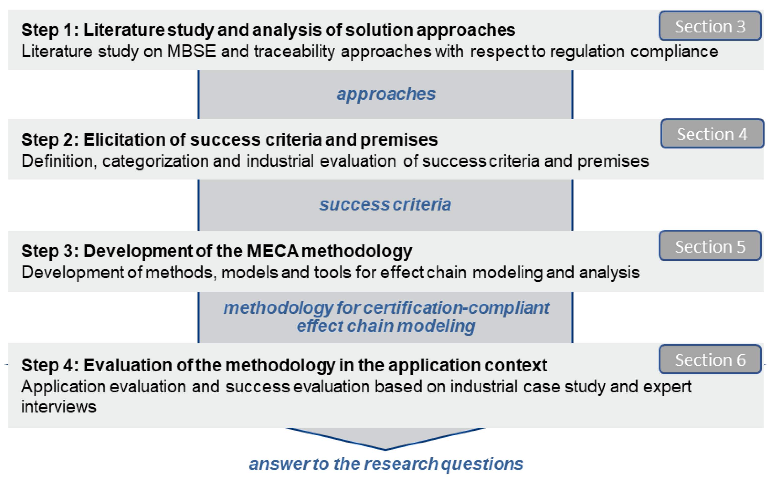
2. Scientific Approach
3. State of the Art
3.1. Regulations
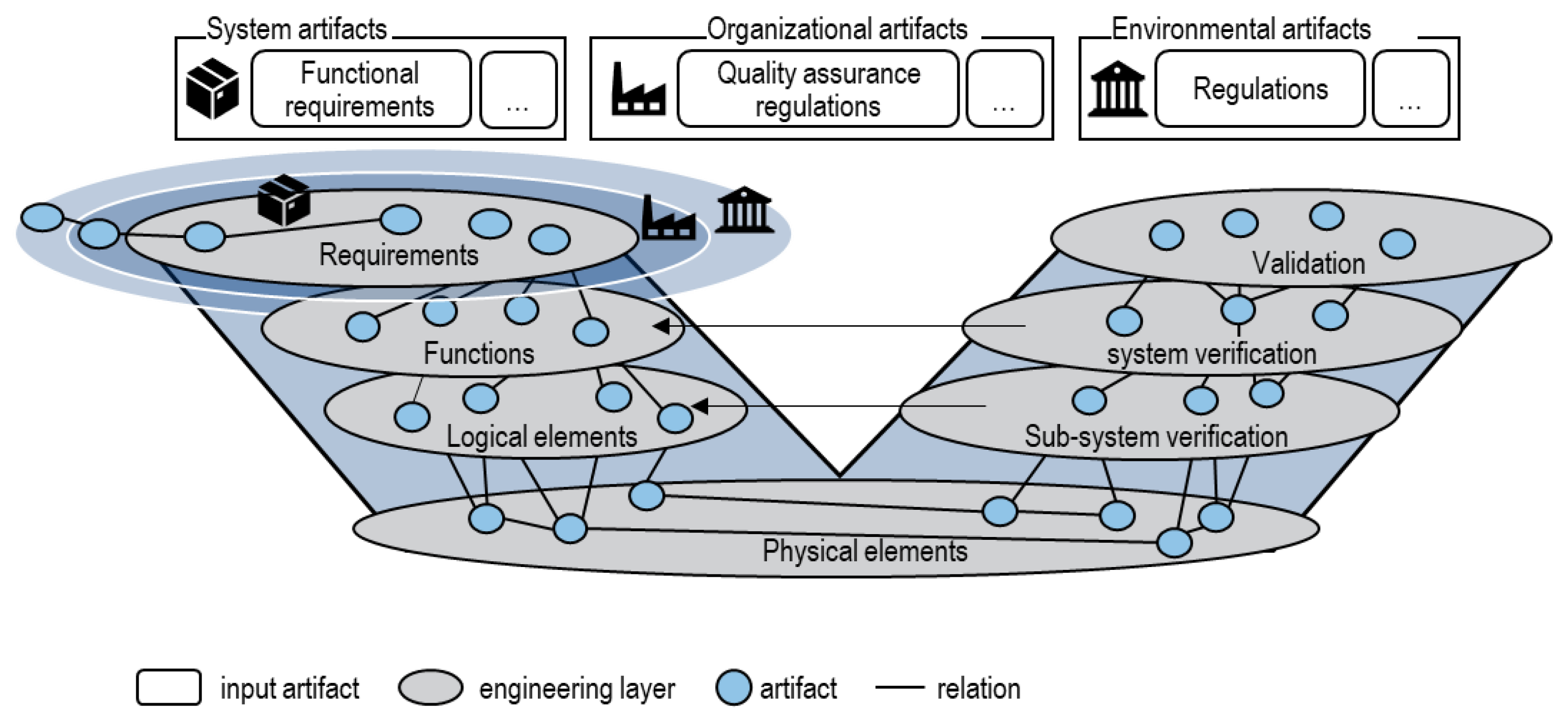
3.2. Traceability
3.3. Model-Based Systems Engineering Approaches
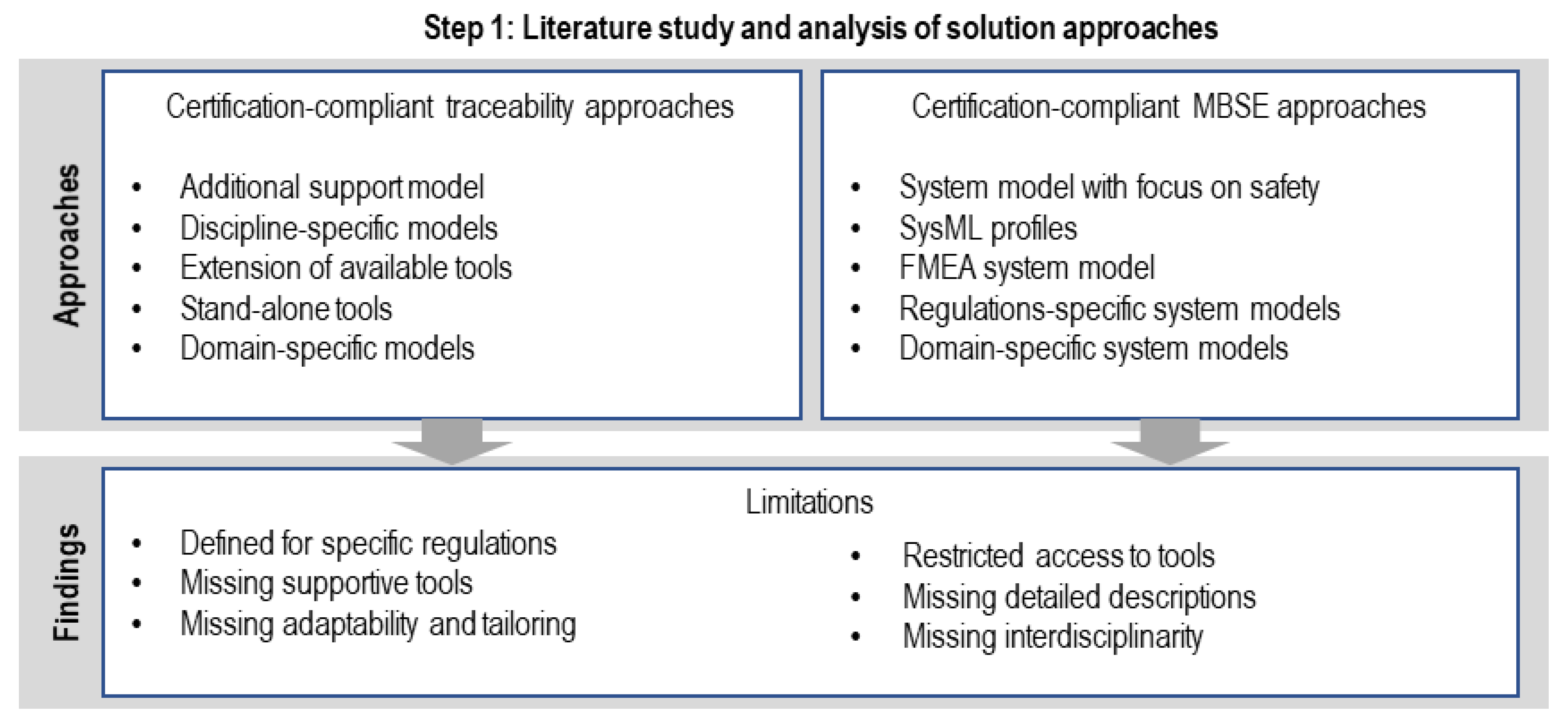
3.4. Identification of Existing Modeling Approaches
3.5. Certification-Compliant Traceability Approaches
3.6. Certification-Compliant MBSE Approaches
4. Success Criteria for the Methodology
- P-1: Availability of required software;
- P-2: Availability of required information;
- P-3: Compatibility of existing IT infrastructure.
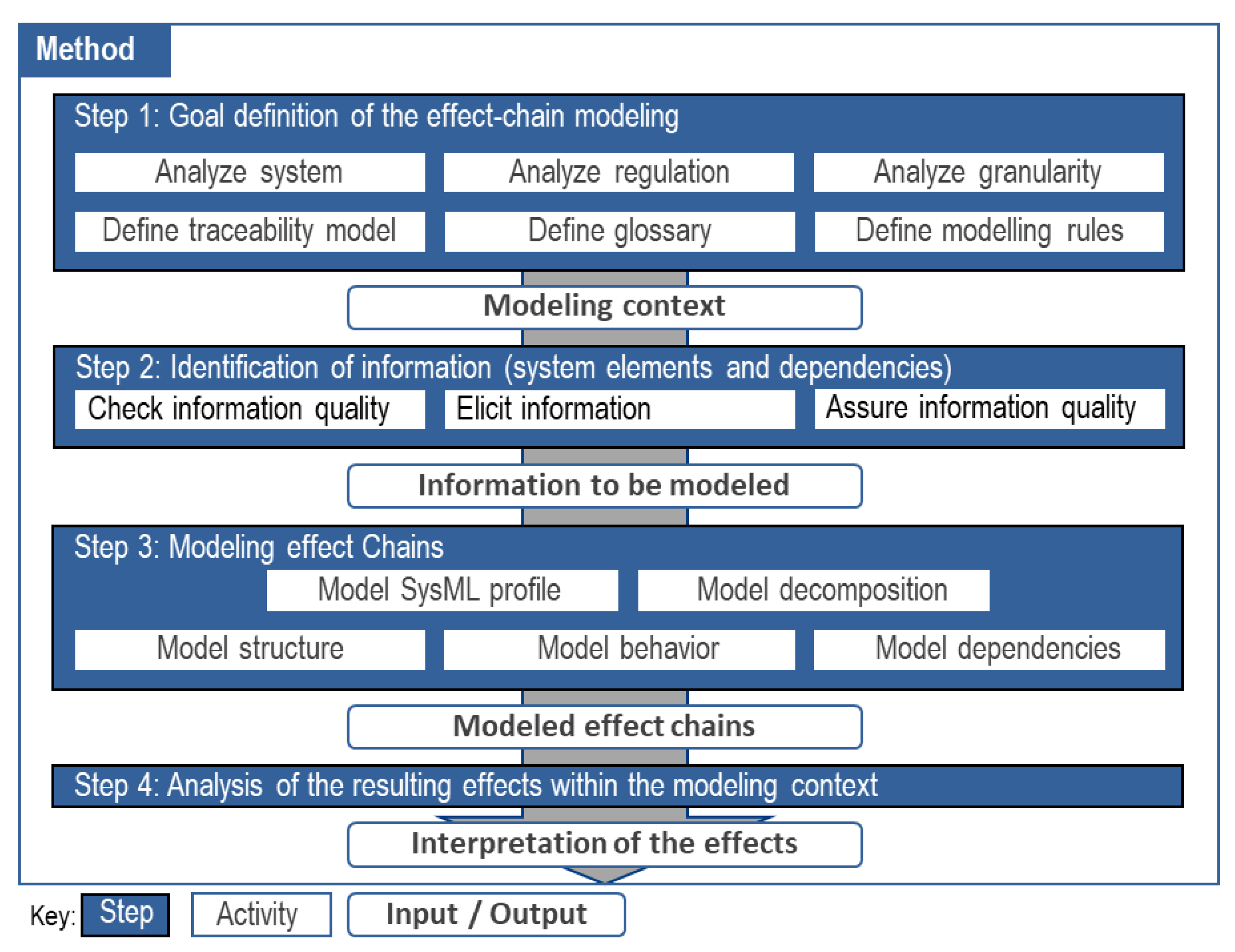
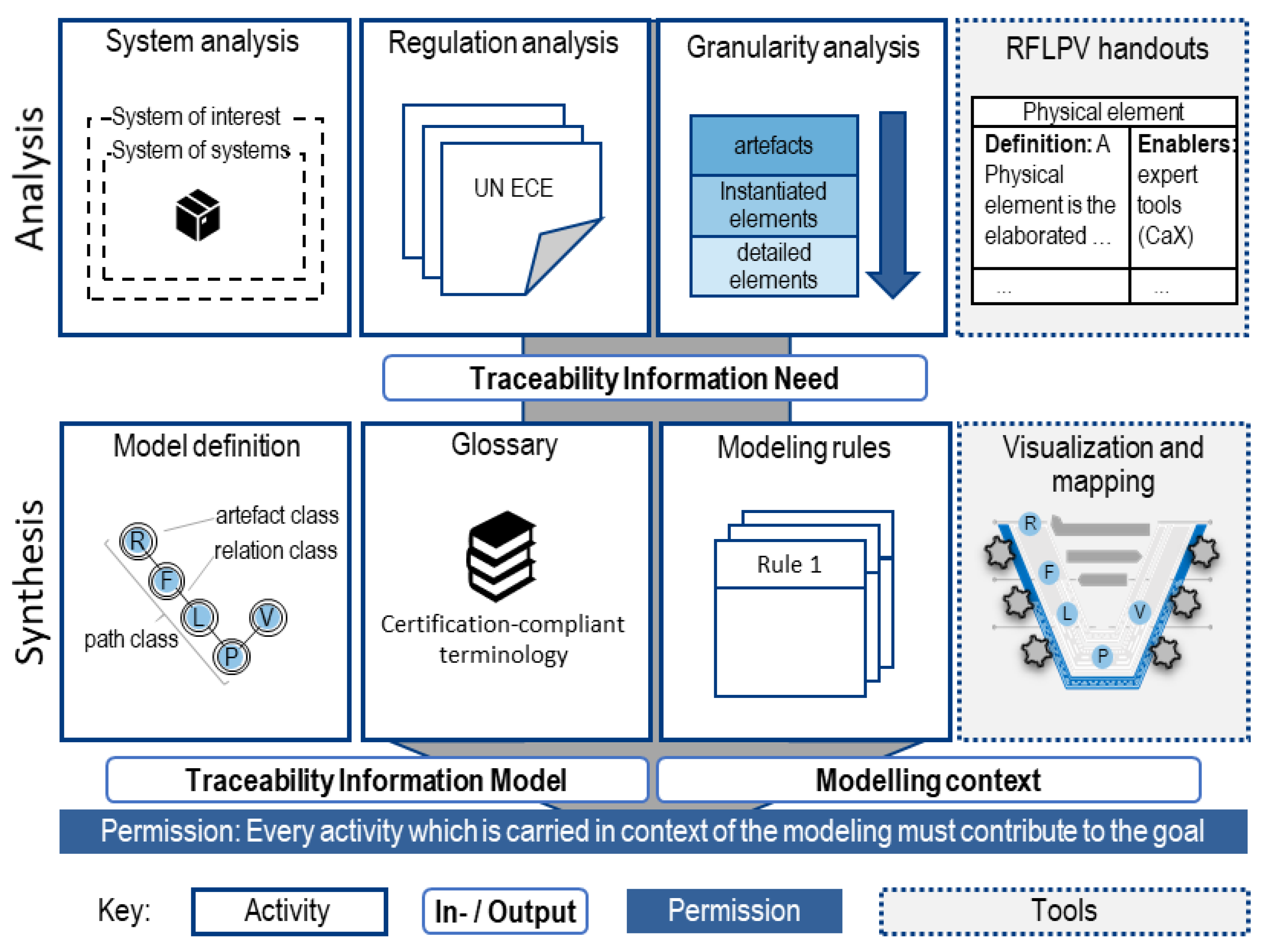
5. Methodology for Certification-Compliant Effect-Chain Modeling
- Step 1: Goal definition of effect-chain modeling
- What are the traceable artifacts that shall be represented?
- What are the relations and characteristics of the artifacts?
- Who are the actors and roles that are included in the modeling process?
- Which information granularity level shall be used to trace every engineering artifact?
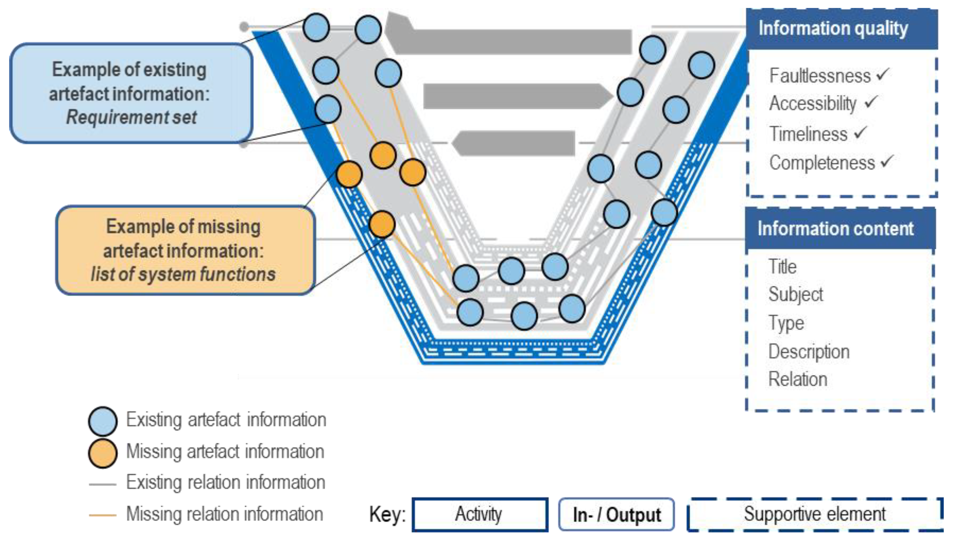
- Step 2: Identification of information
- Check information availability
- Elicit information
- Assure information quality
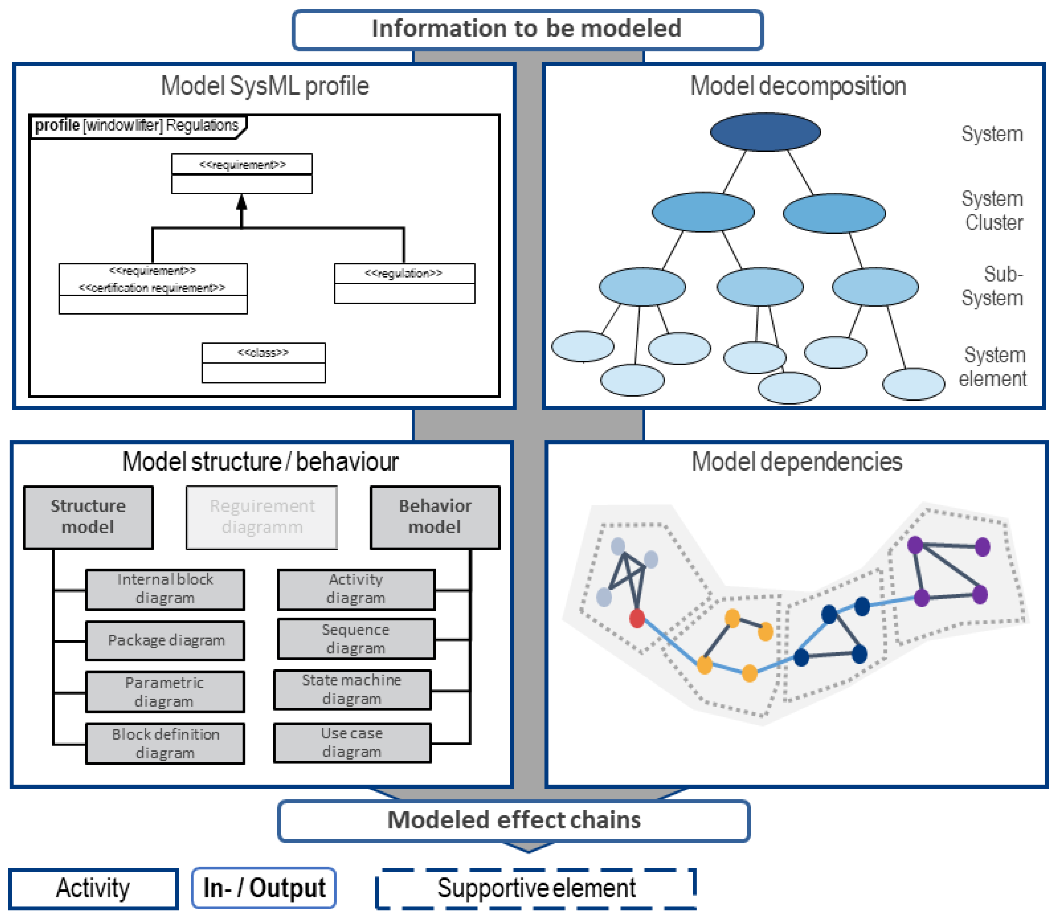
- Step 3: Modeling effect chains
- Model SysML profile
- Model decomposition
- Model structure
- Model behavior
- Model dependencies
- Is the model’s scope sufficient to meet its intended use?
- Is the model complete relative to its scope?
- Is the model consistent and understandable?
- Step 4: Analysis of the effects within the modeling context
6. Evaluation
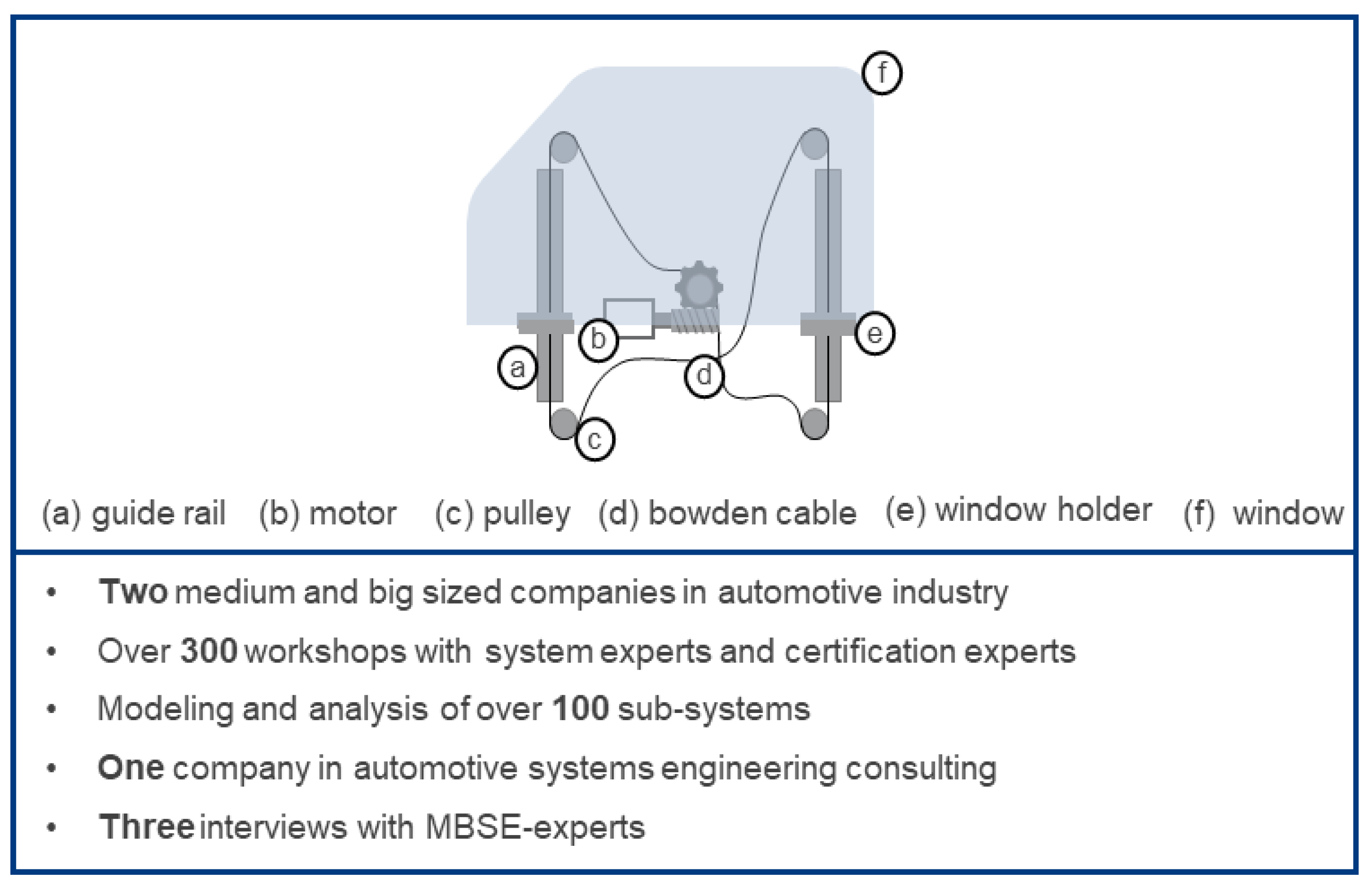
6.1. Evaluation of the Methodology in the Application Context
- Step 1: Goal definition for effect-chain modeling
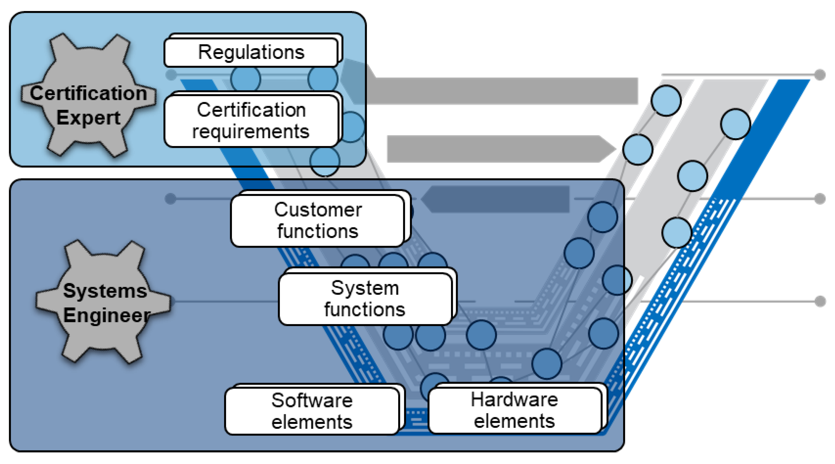
- Artifact classes: Artifact classes are regulations, certification requirements, customer functions, system functions, hardware components, and software components which are modeled as stereotyped SysML <<Block>> elements.
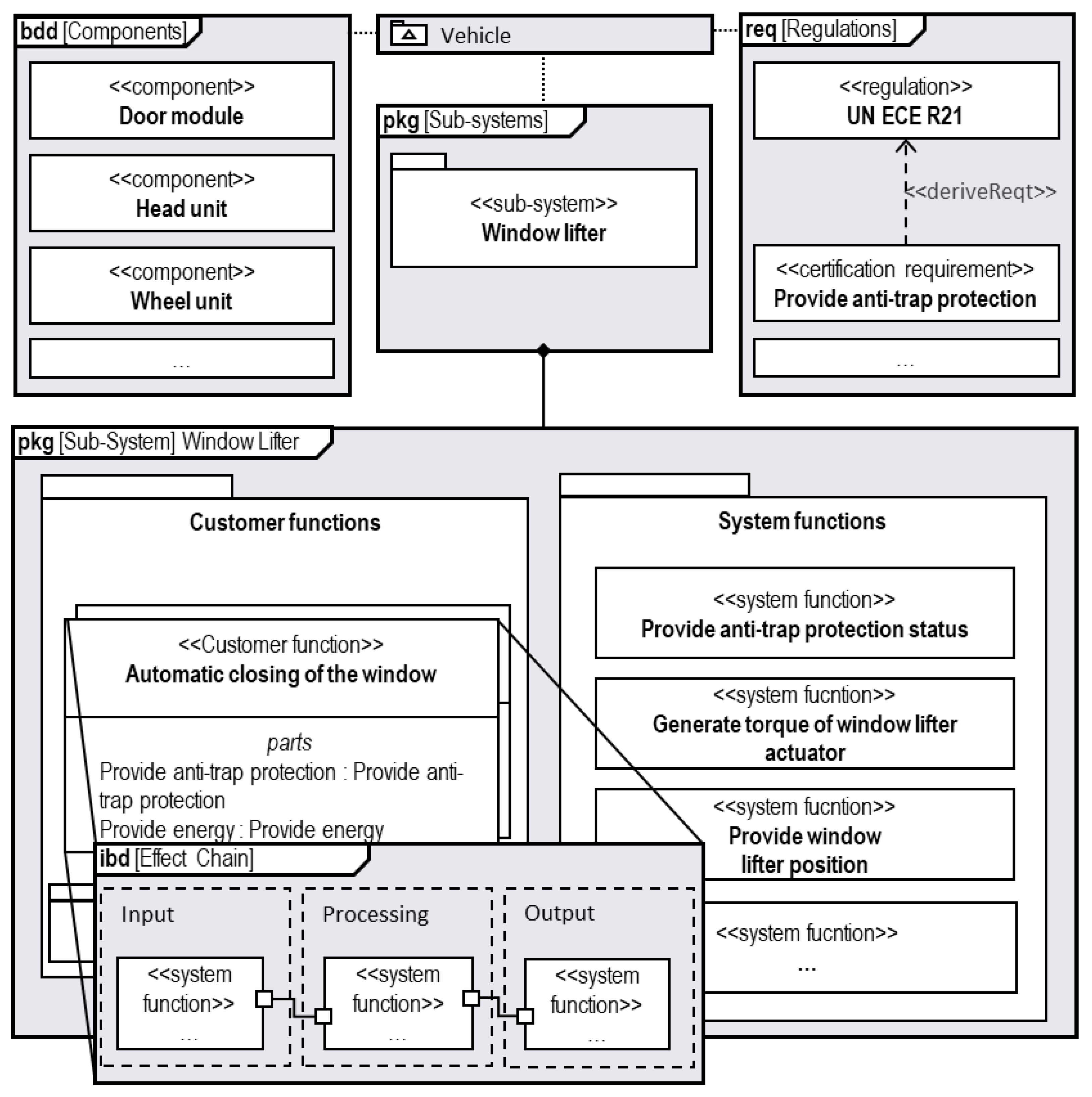
- Link classes: The link classes contain allocations of system functions to regulations and components as well as connectors between system functions and are modeled with the aid of the standard SysML model elements <<allocate>> and <<connector>> [37].
- Path classes: The main path class is the linkage between regulations allocated to the functional behavior of system functions implemented on components and modeled with the aid of standard SysML diagrams [37] (pgk, req, bdd, ibd).
- -
- System function (SF) = A system function executes a customer function in interaction with other system functions.
- -
- Customer function (CF) = A customer function is executed by a sub-system and represents a specific system that is recognizable by a customer. Every customer function is implemented by one or more system functions.
- Always refer to the system function of a system to model dependencies to other systems.
- Map regulation to system function, not to customer functions.
- For mapping relations between different systems, system functions are used.
- Use bidirectional connectors without naming to connect system functions.
- Define ports for each interface between system functions and name them according to the transmitted information.
- Categorize the system functions of a customer function into the categories: input, processing, and output.
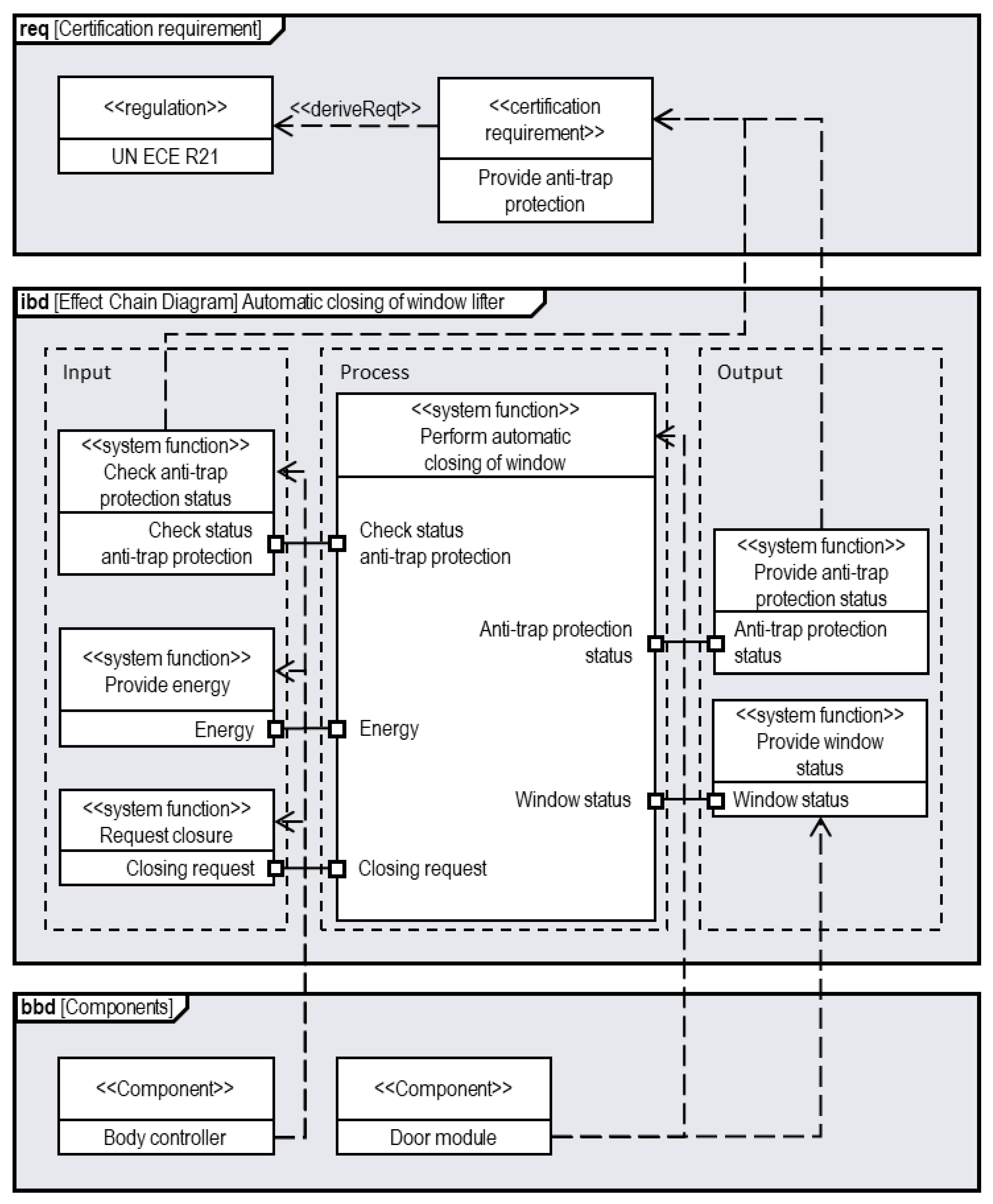
- Step 2: Information Elicitation
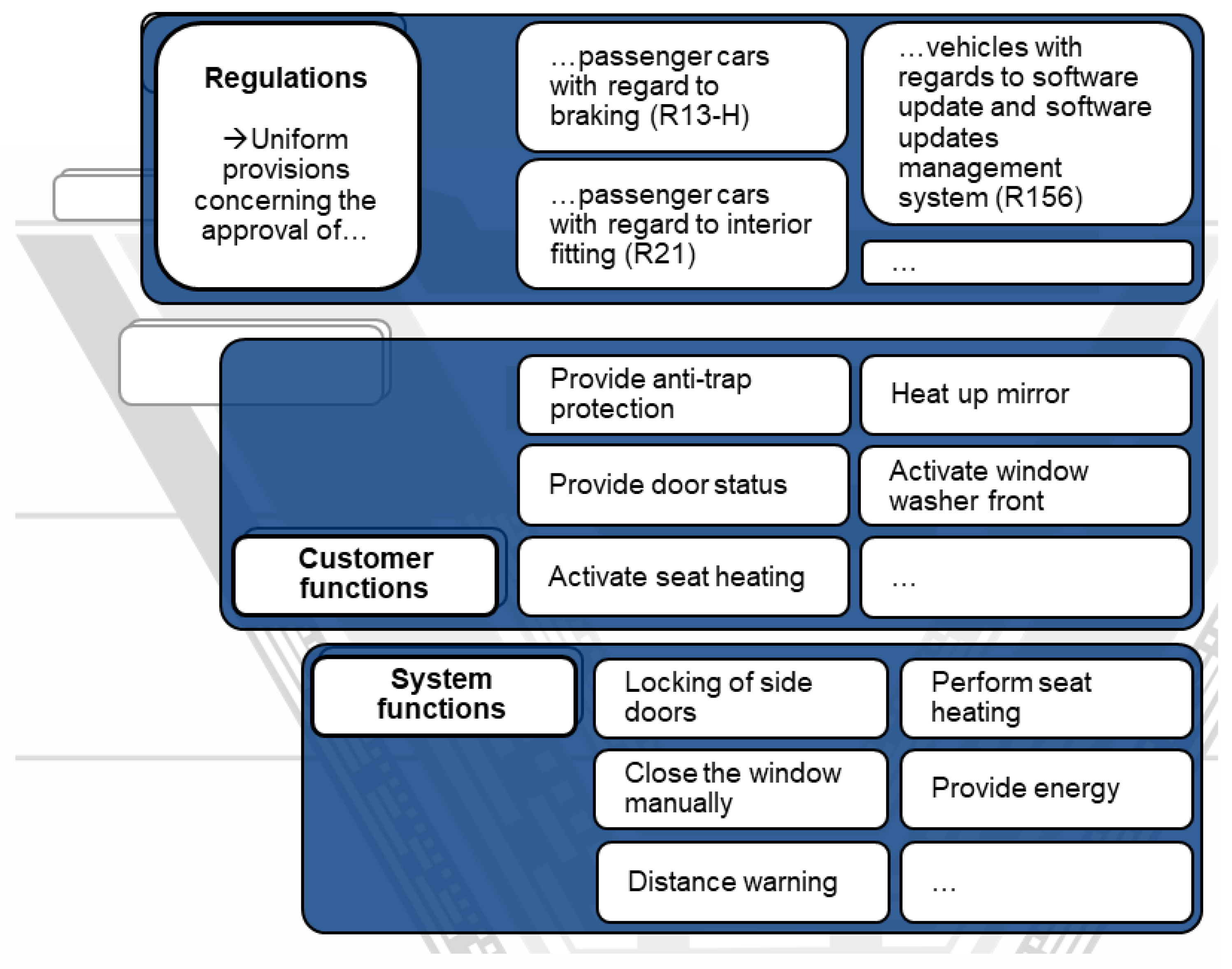
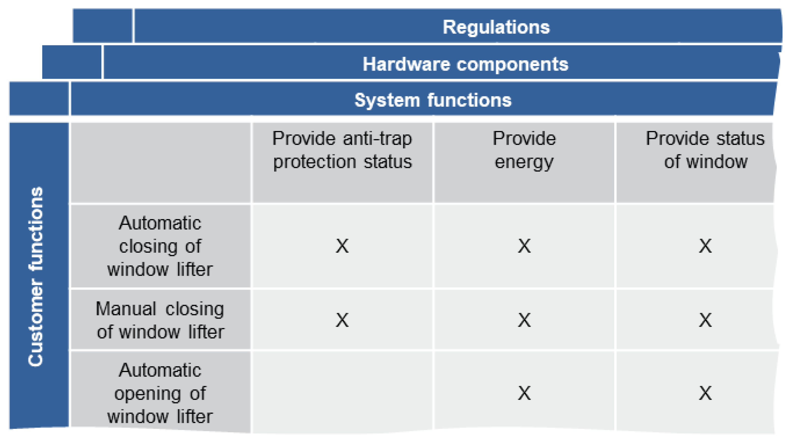
- The customer function “Automatic closing of window lifter” is executed by the system functions “Provide anti-trap protection” and “Provide status of window” among other system functions.
- The system function “Provide status of window” is implemented on the ECU “Door module”.
- The R 21 demands the system function “Anti-trap protection window lifter”.

- Step 3: Modeling of effect chains
- Step 4: Analysis of effect-chain model
6.2. Evaluation of Success Criteria
6.3. Evaluation of Input Success Criteria
6.4. Evaluation of Output Success Criteria
6.5. Evaluation of Application Success Criteria
6.6. Evaluation of Methodology Success Criteria
6.7. Evaluation of Premises
7. Discussion
8. Conclusions
Author Contributions
Funding
Informed Consent Statement
Data Availability Statement
Conflicts of Interest
References
- International Council on Systems Engineering. Systems Engineering Vision 2035, Engineering Solutions for a better World; T INCOSE Central Office: San Diego, USA, 2021. [Google Scholar]
- Gräβler, I. Umsetzungsorientierte Synthese mechatronischer Referenzmodelle: Implementation-oriented synthesis of mechatronic reference models. In Konferenzband der VDI Mechatronik; Fachtagung Mechatronik: Dortmund, Germany, 12–13 March 2015; pp. 167–172. [Google Scholar]
- Gräβler, I.; Wiechel, D.; Koch, A.-S.; Preuβ, D.; Oleff, C. Model-based effect-chain analysis for complex systems. In Proceedings of the 17th International Design Conference, Cavtat, Croatia, 23–26 May 2022; Cambridge University Press: Cambridge, UK, 2022. [Google Scholar]
- Rempel, P.; Mäder, P.; Kuschke, T.; Cleland-Huang, J. Mind the gap: Assessing the conformance of software traceability to relevant guidelines. In Proceedings of the ICSE ‘14: 36th International Conference on Software Engineering, Hyderabad, India, 31 May–7 June 2014; Jalote, P., Briand, L., van der Hoek, A., Eds.; ACM: New York, NY, USA, 2014; pp. 943–954. ISBN 9781450327565. [Google Scholar]
- Regan, G.; Biro, M.; Flood, D.; McCaffery, F. Assessing traceability-practical experiences and lessons learned. J. Softw. Evol. Proc. 2015, 27, 591–601. [Google Scholar] [CrossRef] [Green Version]
- Štorga, M.; Marjanović, D.; Savšek, T. Reference model for traceability records implementation in engineering design environment. In Proceedings of the ICED 11–18th International Conference on Engineering Design: Impacting Society Through Engineering Design, Lyngby/Copenhagen, Denmark, 15–19 August 2011; pp. 173–182. [Google Scholar]
- 610.12-1990 IEEE; Standard Glossary of Software Engineering Terminology. IEEE/Institute of Electrical and Electronics Engineers Incorporated: Piscataway, NJ, USA, 1983; ISBN 978-0-7381-0391-4.
- VDA QMC Working Group 13/Automotive SIG. In Proceedings of the Automotive SPICE: Process Reference Model Process Assessment Model, 656th ed. (Automotive SPICE Version 3.1), Berlin, Germany, 2017. Available online: https://www.automotivespice.com/fileadmin/software-download/AutomotiveSPICE_PAM_31.pdf (accessed on 2 February 2023).
- Nair, S.; de La Vara, J.L.; Sen, S. A review of traceability research at the requirements engineering conferencere@21. In Proceedings of the 2013 IEEE 21st International Requirements Engineering Conference (RE), Rio de Janeiro, RJ, Brazil, 15–19 July 2013; IEEE: Piscataway, NJ, USA, 2013; pp. 222–229. ISBN 978-1-4673-5765-4. [Google Scholar]
- Gräβler, I.; Pöhler, A. Produktentstehung im Zeitalter von Industrie 4.0. In Handbuch Gestaltung Digitaler und Vernetzter Arbeitswelten; Maier, G.W., Engels, G., Steffen, E., Eds.; Springer: Berlin/Heidelberg, Germany, 2020; pp. 383–403. ISBN 978-3-662-52898-3. [Google Scholar]
- Dean, J.; Henderson, C.; Gardner, J. Model-Based Systems Engineering as an Enabler for Regulatory Design Compliance. INCOSE Int. Symp. 2012, 22, 2266–2278. [Google Scholar] [CrossRef]
- Laufenberg, L. Methodik zur Integrierten Projektgestaltung für die Situative Umsetzung des Simultaneous Engineering; Shaker: Aachen, Germany, 1996. (In Germany) [Google Scholar]
- Gräβler, I. Informations-und zeitbasiertes Controlling einer Integrierten Konstruktion und Arbeitsplanung, Als Ms. gedr; Shaker: Aachen, Germany, 2000; ISBN 3-8265-7011-1. (In Germany) [Google Scholar]
- Ulrich, H. Anwendungsorientierte Wissenschaft. Die Unternehm. 1982, 36, 1–10. (In Germany) [Google Scholar]
- Blessing, L.T.M.; Chakrabarti, A. DRM, a Design Research Methodology, 1. Auflage; Springer: London, UK, 2009; ISBN 978-1-84882-587-1. [Google Scholar]
- Andrianarison, E.; Piques, J.-D. SysML for embedded automotive Systems: A practical approach. In Proceedings of the ERTS2, Embedded Real Time Software & Systems, Toulouse, France, May 2010. [Google Scholar]
- Amalfitano, D.; de Simone, V.; Maietta, R.R.; Scala, S.; Fasolino, A.R. Using tool integration for improving traceability management testing processes: An automotive industrial experience. J. Softw. Evol. Proc. 2019, 31, e2171. [Google Scholar] [CrossRef]
- AS 9100: (R) Quality Management Systems-Requirements for Aviation, Space, Rev. D.; SAE International: Warrendale, PA, USA, 2016.
- Barbosa, P.; Leite, F.; Santos, D.; Figueiredo, A.; Galdino, K. Introducing Traceability Information Models in Connected Health Projects. In Proceedings of the 2018 IEEE 31st International Symposium on Computer-Based Medical Systems (CBMS), Karlstad, Sweden, 18–21 June 2018; IEEE: Piscataway, NJ, USA, 2018; pp. 18–23. ISBN 978-1-5386-6060-7. [Google Scholar]
- Brandejsky, T. Problems of En 50 128: 2011 Railway Standard. In Scientific Student Conference Interoperability of Railway Transport-(iricon 2016); Jirova, J., Reznickova, J., Eds.; Czech Technical Univ Prague: Prague, Czechia, 2016; pp. 1–3. ISBN 978-80-01-06022-3. [Google Scholar]
- ISO/IEC/IEEE 24765 2010(E); ISO/IEC/IEEE International Standard-Systems and Software Engineering–Vocabulary. IEEE: Piscataway, NJ, USA, 2010; pp. 1–418. [CrossRef]
- Holtmann, J.; Steghofer, J.-P.; Rath, M.; Schmelter, D. Cutting through the Jungle: Disambiguating Model-based Traceability Terminology. In Proceedings of the 2020 IEEE 28th International Requirements Engineering Conference (RE), Zurich, Switzerland, 31 August–4 September 2020; IEEE: Piscataway, NJ, USA, 2020; pp. 8–19. ISBN 978-1-7281-7438-9. [Google Scholar]
- Gotel, O.; Finkelstein, C.W. An analysis of the requirements traceability problem. In Proceedings of the IEEE International Conference on Requirements Engineering, Colorado Springs, CO, USA, 18–22 April 1994; IEEE Comput. Soc. Press: Los Alamitos, CA, USA, 1994; pp. 94–101. ISBN 0-8186-5480-5. [Google Scholar]
- Hamilton, V.L.; Beeby, M.L. Issues of traceability in integrating tools. In Proceedings of the IEE Colloquium on Tools and Techniques for Maintaining Traceability During Design, London, UK, 2 December 1991; IET: Hong Kong, China. [Google Scholar]
- Storga, M. Traceability in product development. In Proceedings of the Design 2004: The 8th International Design Conference, Dubrovnik, Croatia, 18–21 May 2004; pp. 911–918. [Google Scholar]
- Rempel, P.; Mader, P. A quality model for the systematic assessment of requirements traceability. In Proceedings of the 2015 IEEE 23rd International Requirements Engineering Conference (RE), Ottawa, ON, Canada, 24–28 August 2015; IEEE: Piscataway, NJ, USA, 2015; pp. 176–185. ISBN 978-1-4673-6905-3. [Google Scholar]
- Gotel, O.; Cleland-Huang, J.; Hayes, J.H.; Zisman, A.; Egyed, A.; Grünbacher, P.; Dekhtyar, A.; Antoniol, G.; Maletic, J.; Mäder, P. Traceability Fundamentals. In Software and Systems Traceability; Cleland-Huang, J., Gotel, O., Zisman, A., Eds.; Springer: London, UK, 2012; pp. 3–22. ISBN 978-1-4471-2238-8. [Google Scholar]
- Lindvall, M.; Sandahl, K. Practical Implications of Traceability. Softw. Pract. Exper. 1996, 26, 1161–1180. [Google Scholar] [CrossRef]
- Mader, P.; Gotel, O.; Philippow, I. Getting back to basics: Promoting the use of a traceability information model in practice. In 2009 ICSE Workshop on Traceability in Emerging Forms of Software Engineering; IEEE: Piscataway, NJ, USA, 2009. [Google Scholar]
- Wohlrab, R.; Steghofer, J.-P.; Knauss, E.; Maro, S.; Anjorin, A. Collaborative Traceability Management: Challenges and Opportunities. In Proceedings of the 2016 IEEE 24th International Requirements Engineering Conference (RE), Beijing, China, 12–16 September 2016; IEEE: Piscataway, NJ, USA, 2016; pp. 216–225. ISBN 978-1-5090-4121-3. [Google Scholar]
- Mader, P.; Gotel, O.; Philippow, I. Motivation Matters in the Traceability Trenches. In Proceedings of the 2009 17th IEEE International Requirements Engineering Conference (RE), Atlanta, GA, USA, 31 August–4 September 2009; IEEE: Piscataway, NJ, USA, 2009; pp. 143–148. ISBN 978-0-7695-3761-0. [Google Scholar]
- Ramesh, B.; Jarke, M. Toward reference models for requirements traceability. IIEEE Trans. Softw. Eng. 2001, 27, 58–93. [Google Scholar] [CrossRef] [Green Version]
- Aizenbud-Reshef, N.; Nolan, B.T.; Rubin, J.; Shaham-Gafni, Y. Model traceability. IBM Syst. J. 2006, 45, 515–526. [Google Scholar] [CrossRef]
- Delligatti, L. SysML Distilled: A Brief Guide to the Systems Modeling Language; Addison-Wesley: Upper Saddle River, NJ, USA; New York, NY, USA, 2014; ISBN 978-0-321-92786-6. [Google Scholar]
- International Council on Systems Engineering. INCOSE Systems Engineering Vision 2020; INCOSE Central Office: San Diego, CA, USA, 2007. [Google Scholar]
- Object Management Group. OMG: Unified Modeling Language Infrastructure Specification, Version 2.0. Available online: https://www.omg.org/spec/UML/2.0/Superstructure/PDF (accessed on 12 October 2020).
- Object Management Group. OMG Systems Modeling Language (OMG SysML™). Available online: https://sysml.org/.res/docs/specs/OMGSysML-v1.6-19-11-01.pdf (accessed on 30 January 2023).
- Friedenthal, S.; Moore, A.; Steiner, R. A Practical Guide to SysML: The Systems Modeling Language, 3rd ed.; Elsevier: Amsterdam, The Netherlands; Morgan Kaufmann: Waltham, MA, USA, 2015; ISBN 9780128002025. [Google Scholar]
- Weilkiens, T. Systems Engineering mit SysML/UML: Modellierung, Analyse, Design, 3rd ed.; dpunkt: Heidelberg, Germany, 2014; ISBN 9783864900914. [Google Scholar]
- Bajaj, M.; Backhaus, J.; Walden, T.; Waikar, M.; Zwemer, D.; Schreiber, C.; Issa, G.; Martin, L. Graph-Based Digital Blueprint for Model Based Engineering of Complex Systems. INCOSE Int. Symp. 2017, 27, 151–169. [Google Scholar] [CrossRef]
- Holt, J. Systems Engineering Demystified: A Practitioner’s Handbook for Developing Complex Systems Using a Model-Based Approach; Packt Publishing: Birmingham, UK; Mumbai, India, 2021; ISBN 978-1-83898-580-6. [Google Scholar]
- Chami, M.; Bruel, J.-M. A Survey on MBSE Adoption Challenges; Wiley Interscience Publications: Hoboken, NJ, USA, 2018. [Google Scholar]
- Dick, J.; Hull, E.; Jackson, K. DOORS: A Tool to Manage Requirements. In Requirements Engineering; Dick, J., Hull, E., Jackson, K., Eds.; Springer International Publishing: Cham, Switzerland, 2017; pp. 187–206. ISBN 978-3-319-61072-6. [Google Scholar]
- Lavazza, L.; Valetto, G. Enhancing requirements and change management through process modelling and measurement. In Proceedings of the ICRE2000: IEEE International Conference on Requirements Engineering, Schaumburg, IL, USA, 19–23 June 2000; pp. 106–115. [Google Scholar]
- Pinheiro, F.; Goguen, J.A. An object-oriented tool for tracing requirements. IEEE Softw. 1996, 13, 52–64. [Google Scholar] [CrossRef] [Green Version]
- Bode, S.; Lehnert, S.; Riebisch, M. Comprehensive model integration for dependency identification with EMFTrace. In Proceedings of the MDSM2011 and SQM 2011, Ilmenau, Germany, March 2011; pp. 17–20. [Google Scholar]
- Hegedüs, Á.; Horváth, Á.; Ráth, I.; Starr, R.R.; Varró, D. Query-driven soft traceability links for models. Softw. Syst. Model. 2016, 15, 733–756. [Google Scholar] [CrossRef]
- Smith, T.J. READS: A requirements engineering tool. In Proceedings of the [1993] IEEE International Symposium on Requirements Engineering, San Diego, CA, USA, 4–6 January 1993; IEEE Computer Society Press: Los Alamitos, CA, USA, 1993; pp. 94–97. ISBN 0-8186-3120-1. [Google Scholar]
- Weilkiens, T.; Berres, A.; Endler, D.; Haarer, A.; Lalitsch-Schneider, C.; Krammer, M.; Martin, H. System Safety in SysML. In Tag des Systems Engineering: Ulm, 11–13 November 2015; Schulze, S.-O., Muggeo, C., Eds.; Hanser: München, Germany, 2016; ISBN 9783446447288. [Google Scholar]
- David, P.; Shawky, M. Supporting ISO 26262 with SysML, Benefits and Limits. In Proceedings of the ESREL, Rhodes, Greece, September 2010; p. 8. [Google Scholar]
- Valdivia Dabringer, M.L.; Dybov, A.; Fresemann, C.; Stark, R. Towards Integrated Safety Analysis as Part of Traceable Model-Based Systems Engineering. Proc. Des. Soc. 2022, 2, 2005–2014. [Google Scholar] [CrossRef]
- Hillenbrand, M. Funktionale Sicherheit nach ISO 26262 in der Konzeptphase der Entwicklung von Elektrik/Elektronik Architekturen von Fahrzeugen; Zugl.: Karlsruhe, Germany; KIT Scientific Publishing: Karlsruhe, Germany, 2012; ISBN 978-3-86644-803-2. [Google Scholar]
- Bleu-Laine, M.-H.; Bendarkar, M.V.; Xie, J.; Briceno, S.I.; Mavris, D.N. A Model-Based System Engineering Approach to Normal Category Airplane Airworthiness Certification. In Proceedings of the AIAA Aviation 2019 Forum, Dallas, TX, USA, 17–21 June 2019; American Institute of Aeronautics and Astronautics: Reston, VA, USA, 2019; ISBN 978-1-62410-589-0. [Google Scholar]
- Zhang, J.; Zhang, X.; Li, H. Requirements Engineering Method Applied in the Civil Aircraft Airframe Segment Development. In Proceedings of the 2020 6th International Conference on Mechanical Engineering and Automation Science (ICMEAS), Moscow, Russia, 29–31 October 2020; IEEE: Piscataway, NJ, USA, 2020; pp. 281–286. ISBN 978-1-7281-9272-7. [Google Scholar]
- Glinski, S.; Fazal, B.; Harrison, E.D.; Bendarkar, M.V.; Fields, T.; Garcia, E.; Mavris, D.N. An MBSE Framework to Identify Regulatory Gaps for Electrified Transport Aircraft. In Proceedings of the 2022 IEEE Transportation Electrification Conference & Expo (ITEC), 2022 IEEE/AIAA Transportation Electrification Conference and Electric Aircraft Technologies Symposium (ITEC+EATS), Anaheim, CA, USA, 15–17 June 2022; IEEE: Piscataway, NJ, USA, 2022; pp. 772–777. ISBN 978-1-6654-0560-7. [Google Scholar]
- Sannier, N.; Baudry, B.; Nguyen, T. Formalizing standards and regulations variability in longlife projects. A challenge for Model-driven engineering. In Proceedings of the 2011 Model-Driven Requirements Engineering Workshop (MoDRE), Trento, Italy, 29 August 2011; IEEE: Piscataway, NJ, USA, 2011; pp. 64–73. ISBN 978-1-4577-0957-9. [Google Scholar]
- Hamraz, B. Engineering Change Modelling Using a Function-Behaviour-Structure Scheme; Apollo-University of Cambridge Repository: Cambridge, MA, USA, 2013. [Google Scholar]
- Walden, D.D.; Roedler, G.J.; Forsberg, K.; Hamelin, R.D.; Shortell, T.M. Systems Engineering Handbook: A Guide for System Life Cycle Processes and Activities, 4th ed.; Wiley: Hoboken, NJ, USA, 2015; ISBN 9781118999400. [Google Scholar]
- Gräβler, I.; Wiechel, D.; Oleff, C. Extended RFLP for complex technical systems. In Proceedings of the 8th IEEE International Symposium on Systems Engineering, ISSE, Vienna, Austria, 24–26 October 2021; IEEE: Piscataway, NJ, USA, 2022. [Google Scholar]
- Gräβler, I.; Wiechel, D.; Pottebaum, J. Role model of model-based systems engineering application. IOP Conf. Ser. Mater. Sci. Eng. 2021, 1097, 12003. [Google Scholar] [CrossRef]
- VDI/VDE. Entwicklung Mechatronischer und Cyber-Physischer Systeme; Beuth Verlag GmbH: Düsseldorf, Germany, 2021. (In Germany) [Google Scholar]
- Graessler, I.; Hentze, J. The new V-Model of VDI 2206 and its validation. At-Automatisierungstechnik 2020, 68, 312–324. [Google Scholar] [CrossRef]
- Gräβler, I.; Hentze, J.; Bruckmann, T. V-Models for Interdisciplinary Systems Engineering. In Proceedings of the DESIGN 2018 15th International Design Conference, DESIGN Conference, Dubrovnik, Croatian, 21–24 May 2018; Design Society: Singapore; pp. 747–756. [Google Scholar]
- Gräβler, I.; Hentze, J.; Yang, X. Eleven Potentials for Mechatronic V-Model. In Proceedings of the International Conference Production Engineering and Management; Lemgo, Germany, 29–30 September 2016, Villmer, F.-J., Padoanao, E., Eds.; 2016; pp. 257–268. ISBN 978-3-946856-00-9. [Google Scholar]
- Eppinger, S.D.; Browning, T.R. Design Structure Matrix Methods and Applications; MIT Press: Cambridge, MA, USA, 2012; ISBN 9780262017527. [Google Scholar]
- Legard, R.; Keegan, J.; Ward, K. In-depth interviews. In Qualitative Research Practice: A Guide for Social Science Students and Researchers, Repr; Ritchie, J., Ed.; SAGE: Los Angeles, CA, USA, 2011; pp. 138–169. ISBN 9780761971108. [Google Scholar]
- Powell, R.A.; Single, H.M. Focus groups. Int. J. Qual. Health Care 1996, 8, 499–504. [Google Scholar] [CrossRef] [PubMed] [Green Version]
- Stvilia, B.; Gasser, L.; Twidale, M.B.; Smith, L.C. A framework for information quality assessment. J. Am. Soc. Inf. Sci. 2007, 58, 1720–1733. [Google Scholar] [CrossRef]
- Krcmar, H. Informationsmanagement, 6., überarb. Aufl.; Springer Gabler: Wiesbaden, Germany, 2015; ISBN 978-3-662-45863-1. (In Germany) [Google Scholar]
- Rohweder, J.P.; Kasten, G.; Malzahn, D.; Piro, A.; Schmid, J. Informationsqualität—Definitionen, Dimensionen und Begriffe. In Daten-und Informationsqualität; Hildebrand, K., Gebauer, M., Hinrichs, H., Mielke, M., Eds.; Vieweg+Teubner: Wiesbaden, Germany, 2008; pp. 25–45. ISBN 978-3-8348-0321-4. (In Germany) [Google Scholar]
- Wang, R.Y.; Strong, D.M. Beyond Accuracy: What Data Quality Means to Data Consumers. J. Manag. Inf. Syst. 1996, 12, 5–33. [Google Scholar] [CrossRef]
- Gräβler, I. A new V-Model for interdisciplinary product engineering. In Engineering for a Changing World, 59th IWK; Ilmenau Scientific Colloquium: Ilmenau, Germany, 11–15 September 2017. [Google Scholar]
- Kleiner, S.; Kramer, C. Model Based Design with Systems Engineering Based on RFLP Using V6. In Smart Product Engineering, Proceedings of the 23rd CIRP Design Conference, Bochum, Germany, 11–13 March 2013; Abramovici, M., Stark, R., Eds.; Springer: Berlin/Heidelberg, Germany, 2013; pp. 93–102. ISBN 9783642308161. [Google Scholar]
- Haberfellner, R.; de Weck, O.L.; Fricke, E. Systems Engineering: Fundamentals and Applications; Birkhäuser: Basel, Switzerland, 2019; ISBN 978-3-030-13430-3. [Google Scholar]
- Pahl, G.; Beitz, W.; Feldhusen, J.; Grote, K.-H. Engineering Design; Springer: London, UK, 2007; ISBN 978-1-84628-318-5. [Google Scholar]
- Stachowiak, H. Allgemeine Modelltheorie; Springer: Wien, Germany, 1973; ISBN 3-211-81106-0. [Google Scholar]
- Gräβler, I.; Wiechel, D.; Thiele, H. Fortschrittskontrolle der Modellierung mechatronischer Produkte: Controlling of the Modeling of Mechatronic Products. In Fachtagung VDI Mechatronik 2022; Bertram, T., Corves, B., Janschek, K., Rinderknecht, S., Eds.; Technische Universität Darmstadt: Darmstadt, Germany, 2022; pp. 49–54. [Google Scholar]
- Gräβler, I.; Oleff, C.; Scholle, P. Method for Systematic Assessment of Requirement Change Risk in Industrial Practice. Appl. Sci. 2020, 10, 8697. [Google Scholar] [CrossRef]
- Menninger, B.; Wiechel, D.; Rackow, S.; Höpfner, G.; Oleff, C.; Berroth, J.; Gräßler, I.; Jacobs, G. Modeling and analysis of functional variance of complex technical systems. In Proceedings of the 33rd Symposium Design for X, Hamburg, Germany, 22–23 September 2022; The Design Society: Glasgow, UK, 2022; p. 10. [Google Scholar]
- Gräβler, I.; Oleff, C.; Hieb, M.; Preuβ, D. Automated Requirement Dependency Analysis for Complex Technical Systems. Proc. Des. Soc. 2022, 2, 1865–1874. [Google Scholar] [CrossRef]
- Gräβler, I.; Oleff, C.; Preuβ, D. Proactive Management of Requirement Changes in the Development of Complex Technical Systems. Appl. Sci. 2022, 12, 1874. [Google Scholar] [CrossRef]
- de-academic.com. Elektrischer Fensterheber. Available online: https://de-academic.com/dic.nsf/dewiki/384632 (accessed on 26 October 2022).
- Jacobs, G.; Konrad, C.; Berroth, J.; Zerwas, T.; Höpfner, G.; Spütz, K. Function-Oriented Model-Based Product Development. In Design Methodology for Future Products; Krause, D., Heyden, E., Eds.; Springer International Publishing: Cham, Switzerland, 2022; pp. 243–263. ISBN 978-3-030-78367-9. [Google Scholar]
- United Nations Economic Commission for Europe. UN Regulation No. 156: Uniform Provisions Concerning the Approval of Vehicles with Regards to Software Update and Software Updates Management System. Available online: https://unece.org/sites/default/files/2021-03/R156e.pdf. (accessed on 30 January 2023).
- United Nations Economic Commission for Europe. UN Regulation No. 21: Uniform Provisions Concerning the Approval of Vehicles with Regards to Their Interior Fittings. Available online: https://unece.org/fileadmin/DAM/trans/main/wp29/wp29regs/r021r2e_1.pdf. (accessed on 30 January 2023).
- Qi, W.; Ovur, S.E.; Li, Z.; Marzullo, A.; Song, R. Multi-Sensor Guided Hand Gesture Recognition for a Teleoperated Robot Using a Recurrent Neural Network. IEEE Robot. Autom. Lett. 2021, 6, 6039–6045. [Google Scholar] [CrossRef]
- Su, H.; Mariani, A.; Ovur, S.E.; Menciassi, A.; Ferrigno, G.; de Momi, E. Toward Teaching by Demonstration for Robot-Assisted Minimally Invasive Surgery. IEEE Trans. Autom. Sci. Eng. 2021, 18, 484–494. [Google Scholar] [CrossRef]
- Gräβler, I.; Dattner, M.; Bothen, M.; Bothen, M. Main Feature List as core success criteria of organizing Requirements Elicitation. In Proceedings of the R&D Management Conference, Mailand, Italy, 30 June–4 July 2018; pp. 1–16. [Google Scholar]
- Specking, E.; Parnell, G.; Pohl, E.; Buchanan, R. Early Design Space Exploration with Model-Based System Engineering and Set-Based Design. Systems 2018, 6, 45. [Google Scholar] [CrossRef] [Green Version]
- Ferris, T.L.; Specking, E.; Jackson, S.; Parnell, G.; Pohl, E. The Fundamental Nature of Resilience of Engineered Systems. INCOSE Int. Symp. 2018, 28, 1311–1321. [Google Scholar] [CrossRef]


| Input | Application |
|---|---|
| SC-1: Integrability of interdisciplinary artifacts | SC-7: Applicability independent of the regulations |
| SC-2: Processability of high number of artifacts | SC-8: Acceptable application effort |
| SC-3: Processability of different data formats | SC-9: Collaborative applicability |
| SC-4: Assurance of information quality | SC-10: Applicability without effect chain related knowledge |
| Output | Methodology |
| SC-5: Indication of resulting effects | SC-11: Ability to model interdisciplinary effects |
| SC-6: Sufficient accuracy of effects | SC-12: Goal-orientation of modeling steps |
| Input | Fulfillment | Application | Fulfillment |
|---|---|---|---|
| SC-1 | ● | SC-7 | ● |
| SC-2 | ● | SC-8 | ◑ |
| SC-3 | ● | SC-9 | ◑ |
| SC-4 | ● | SC-10 | ● |
| Output | Methodology | ||
| SC-5 | ● | SC-11 | ● |
| SC-6 | ● | SC-12 | ● |
Disclaimer/Publisher’s Note: The statements, opinions and data contained in all publications are solely those of the individual author(s) and contributor(s) and not of MDPI and/or the editor(s). MDPI and/or the editor(s) disclaim responsibility for any injury to people or property resulting from any ideas, methods, instructions or products referred to in the content. |
© 2023 by the authors. Licensee MDPI, Basel, Switzerland. This article is an open access article distributed under the terms and conditions of the Creative Commons Attribution (CC BY) license (https://creativecommons.org/licenses/by/4.0/).
Share and Cite
Gräßler, I.; Wiechel, D.; Koch, A.-S.; Sturm, T.; Markfelder, T. Methodology for Certification-Compliant Effect-Chain Modeling. Systems 2023, 11, 154. https://doi.org/10.3390/systems11030154
Gräßler I, Wiechel D, Koch A-S, Sturm T, Markfelder T. Methodology for Certification-Compliant Effect-Chain Modeling. Systems. 2023; 11(3):154. https://doi.org/10.3390/systems11030154
Chicago/Turabian StyleGräßler, Iris, Dominik Wiechel, Anna-Sophie Koch, Tim Sturm, and Thomas Markfelder. 2023. "Methodology for Certification-Compliant Effect-Chain Modeling" Systems 11, no. 3: 154. https://doi.org/10.3390/systems11030154