
The Crosslinking and Porosity Surface Effects of Photoetching Process on Immobilized Polymer-Based Titanium Dioxide for the Decolorization of Anionic Dye

 , ,
, ,  , ,
, ,
Abstract
:1. Introduction
2. Materials and Methods
3. Results
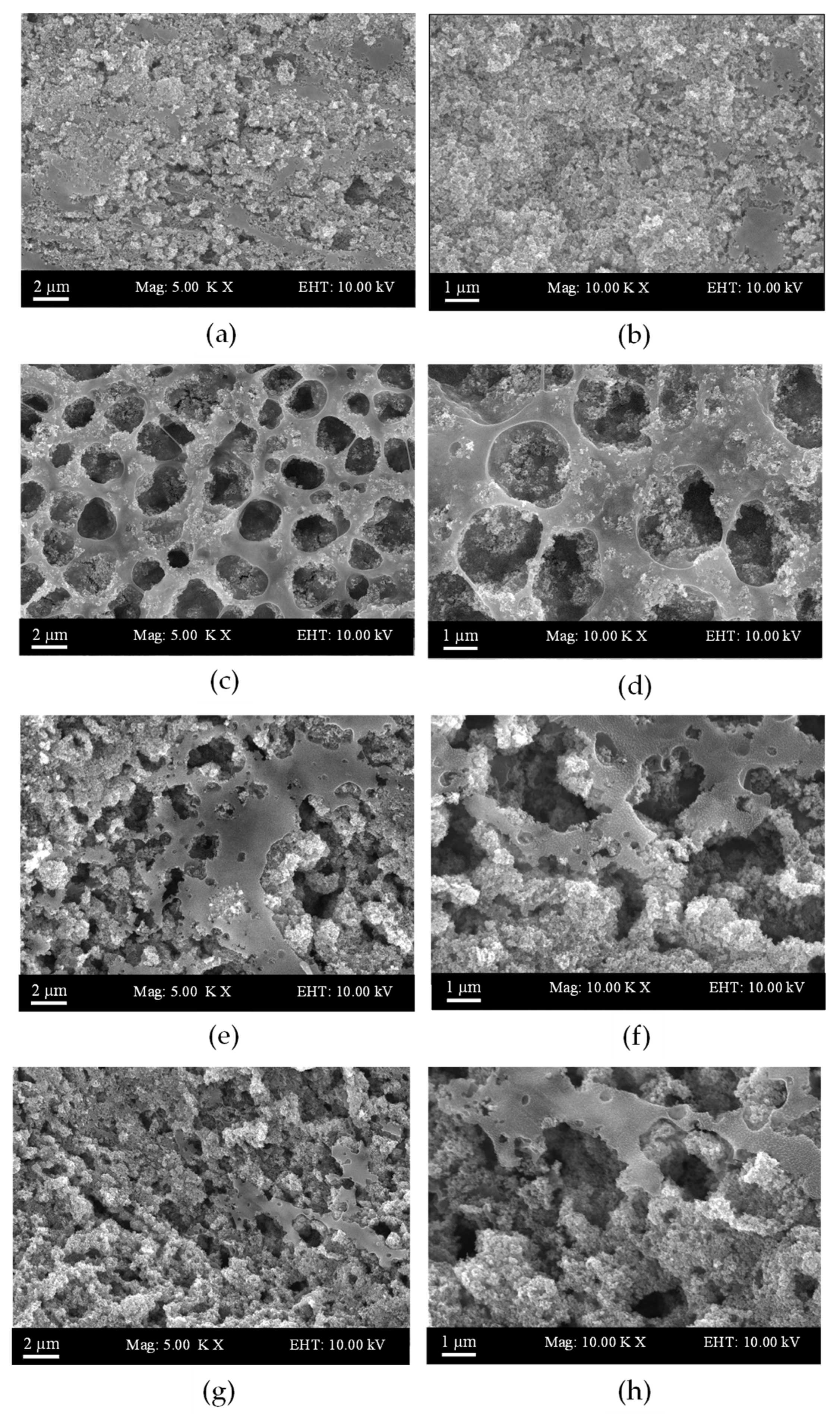
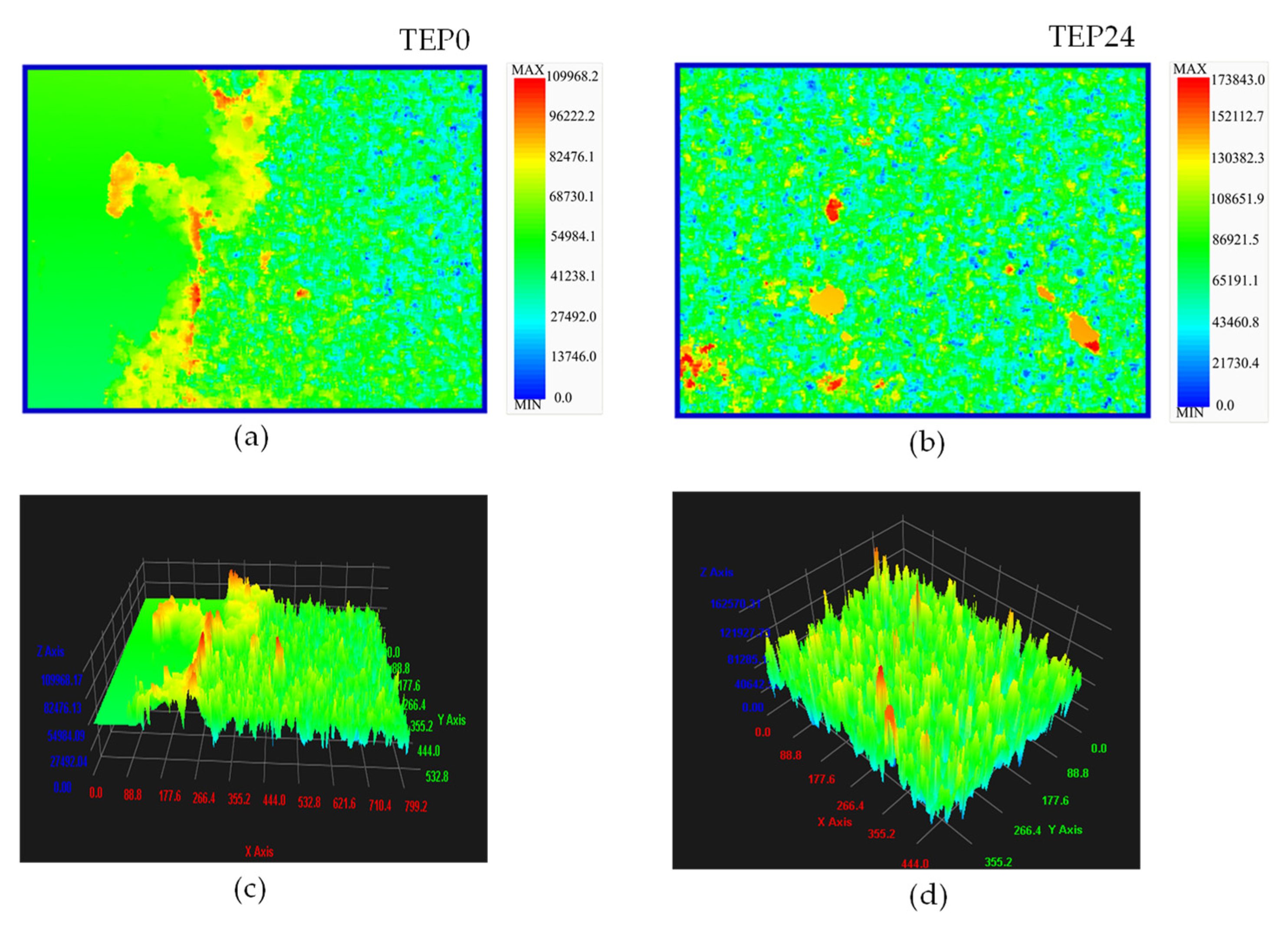
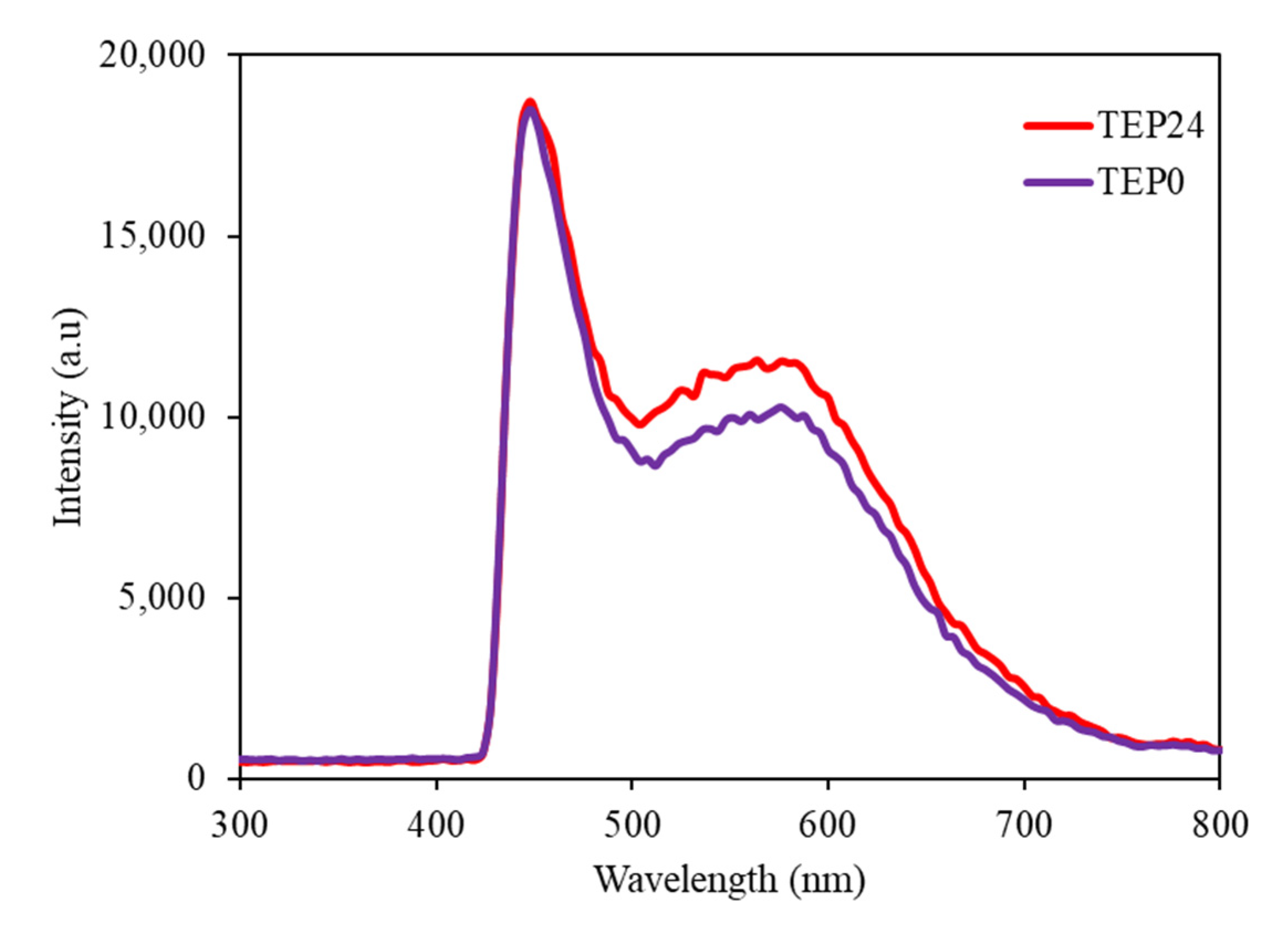
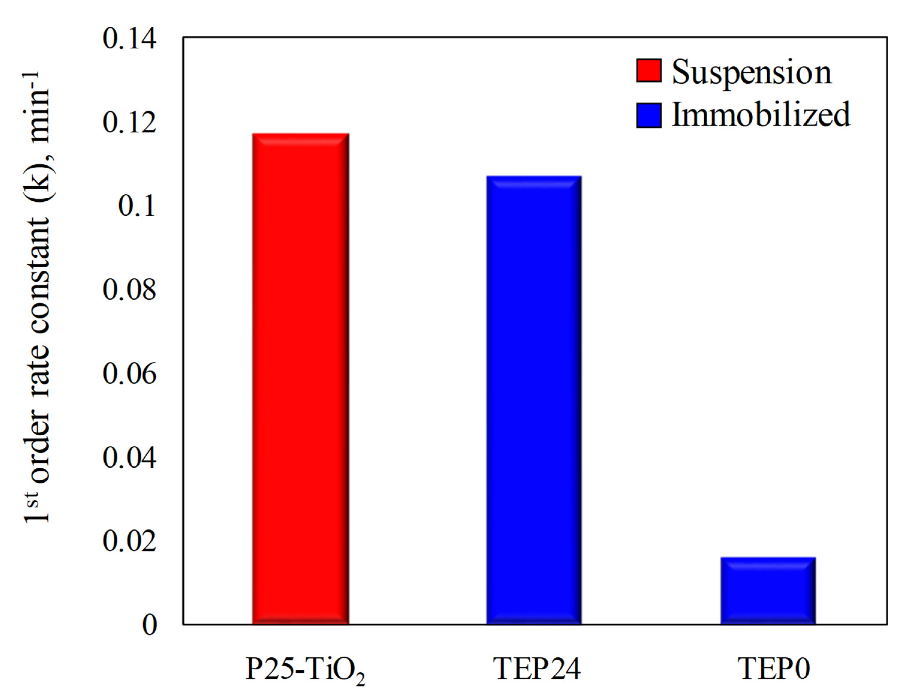
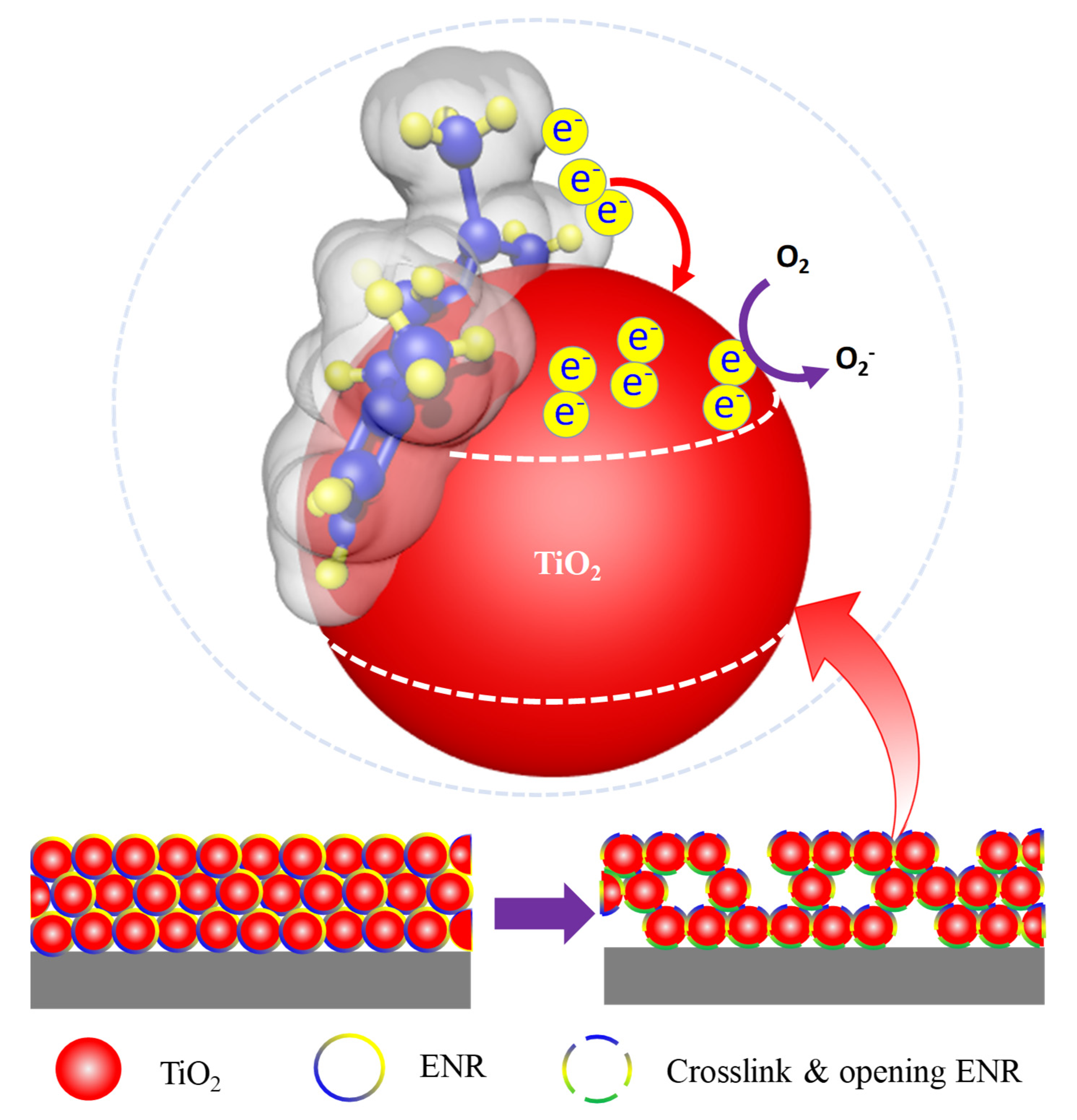
Photodegradation of Immobilized TiO2/ENR/PVC
4. Discussion
Author Contributions
Funding
Data Availability Statement
Acknowledgments
Conflicts of Interest
References
- Aziz, K.H.H. Application of different advanced oxidation processes for the removal of chloroacetic acids using a planar falling film reactor. Chemosphere 2019, 228, 377–383. [Google Scholar] [CrossRef] [PubMed]
- Ijaz, M.; Zafar, M. Titanium dioxide nanostructures as efficient photocatalyst: Progress, challenges and perspective. Int. J. Energy Res. 2021, 45, 3569–3589. [Google Scholar] [CrossRef]
- Mortazavian, S.; Saber, A.; James, D.E. Optimization of photocatalytic degradation of Acid Blue 113 and Acid Red 88 textile dyes in a UV-C/TiO2 suspension system: Application of response surface methodology (RSM). Catalysts 2019, 9, 360. [Google Scholar] [CrossRef] [Green Version]
- Tetteh, E.K.; Rathilal, S.; Naidoo, D.B. Photocatalytic degradation of oily waste and phenol from a local South Africa oil refinery wastewater using response methodology. Sci. Rep. 2020, 10, 1–12. [Google Scholar] [CrossRef]
- Ikhwan, M.S.; Nazeri, N.S.; Natar, N.S.; Abdul Ghani, N.I.; Hamzah, S.R.; Rosli, M.A.; Mohd Ishak, M.A.; Mamauod, S.N.; Mohd Azami, M.S.; Wan Ismail, W.I.N. The surface distribution and recyclability study on photodegradation methylene blue dye of immobilized TiO2 under surfactant effect. Sci. Lett. 2022, 16, 40–50. [Google Scholar]
- Tetteh, E.K.; Rathilal, S.; Asante-Sackey, D.; Chollom, M.N. Prospects of Synthesized Magnetic TiO2-Based Membranes for Wastewater Treatment: A Review. Materials 2021, 14, 3524. [Google Scholar] [CrossRef]
- Nawi, M.A.; Zain, S.M. Enhancing the surface properties of the immobilized Degussa P-25 TiO2 for the efficient photocatalytic removal of methylene blue from aqueous solution. Appl. Surf. Sci. 2012, 258, 6148–6157. [Google Scholar] [CrossRef]
- Nawi, M.A.; Ngoh, Y.S.; Zain, S.M. Photoetching of Immobilized TiO2-ENR50-PVC Composite for Improved Photocatalytic Activity. Int. J. Photoenergy 2012. [Google Scholar] [CrossRef]
- Razak, S.; Nawi, M.A.; Haitham, K. Fabrication, characterization and application of a reusable immobilized TiO2–PANI photocatalyst plate for the removal of reactive red 4 dye. Appl. Surf. Sci. 2014, 319, 90–98. [Google Scholar] [CrossRef]
- Natar, N.S.; Ikhwan, S.; Nazeri, N.S.; Hamzah, S.R.; Rosli, M.A.; Ghani, N.I.; Ishak MA, M.; Razak, S.; Azami, M.S.; Nawawi, W.I. Preparation of water-base immobilized N doped TiO2 using DSAT technique for photocatalytic degradation of methylene blue dye. Mater. Today Proc. 2022, 66, 4036–4044. [Google Scholar] [CrossRef]
- Gonzalez, Z.; Yus, J.; Sanchez-Herencia, A.J.; Dewalque, J.; Manceriu, L.; Henrist, C.; Ferrari, B. A colloidal approach to prepare binder and crack-free TiO2 multilayer coatings from particulate suspensions: Application in DSSCs. J. Eur. Ceram. Soc. 2019, 39, 366–375. [Google Scholar] [CrossRef]
- Jadaa, W.; Prakash, A.; Ray, A.K. Photocatalytic Degradation of Diazo Dye over Suspended and Immobilized TiO2 Catalyst in Swirl Flow Reactor: Kinetic Modeling. Processes 2021, 9, 1741. [Google Scholar] [CrossRef]
- Silva, S.A.; Mineiro, S.L.; Oliveira, R.M.; Nono, M.D.C.A. Processing and Characterization of ZrO2-TiO2 Porous Films by Dip Coating for Application as Environmental Sensors. In Materials Science Forum; Trans Tech Publications Ltd.: Stafa-Zurich, Switzerland, 2018; Volume 930, pp. 631–636. [Google Scholar]
- Peiris, D.S.U.; Ekanayake, P.; Petra, M.I. Stacked rGO–TiO2 photoanode via electrophoretic deposition for highly efficient dye-sensitized solar cells. Org. Electron. 2018, 59, 399–405. [Google Scholar] [CrossRef]
- Zouzelka, R.; Remzova, M.; Brabec, L.; Rathousky, J. Photocatalytic performance of porous TiO2 layers prepared by quantitative electrophoretic deposition from organic solvents. Appl. Catal. Environ. 2018, 227, 70–78. [Google Scholar] [CrossRef]
- Khanmohammadi, S.; Ojaghi-Ilkhchi, M.; Farrokhi-Rad, M. Development of bioglass coating reinforced with hydroxyapatite whiskers on TiO2 nanotubes via electrophoretic deposition. Ceram. Int. 2021, 47, 1333–1343. [Google Scholar] [CrossRef]
- Thompson, W.A.; Perier, C.; Maroto-Valer, M.M. Systematic study of sol-gel parameters on TiO2 coating for CO2 photoreduction. Appl. Catal. Environ. 2018, 238, 136–146. [Google Scholar] [CrossRef]
- Ahadi, S.; Moalej, N.S.; Sheibani, S. Characteristics and photocatalytic behavior of Fe and Cu doped TiO2 prepared by combined sol-gel and mechanical alloying. Solid State Sci. 2019, 96, 105975. [Google Scholar] [CrossRef]
- Estrada-Flores, S.; Martínez-Luévanos, A.; Perez-Berumen, C.M.; García-Cerda, L.A.; Flores-Guia, T.E. Relationship between morphology, porosity, and the photocatalytic activity of TiO2 obtained by sol–gel method assisted with ionic and nonionic surfactants. Boletín Soc. Española Cerámica Vidr. 2020, 59, 209–218. [Google Scholar] [CrossRef]
- Jaramillo-Raquejo, D.; Palacio-Espinosa, C.C.; Ageorges, H. Plasma Spray Parameters of TiO2 Targets Used in Magnetron Sputtering. TecnoLógicas 2020, 23, 135–155. [Google Scholar]
- Kozlovskiy, A.; Shlimas, I.; Dukenbayev, K.; Zdorovets, M. Structure and corrosion properties of thin TiO2 films obtained by magnetron sputtering. Vacuum 2019, 164, 224–232. [Google Scholar] [CrossRef]
- Samiee, M.; Hanachi, M.; Seyedraoufi, Z.S.; Eshraghi, M.J.; Shajari, Y. Biodegradable magnesium alloy coated with TiO2/MgO two-layer composite via magnetic sputtering for orthopedic applications: A study on the surface characterization, corrosion, and biocompatibility. Ceram. Int. 2021, 47, 6179–6186. [Google Scholar] [CrossRef]
- Abdul Ghani, N.; Rosli, M.; Hamzah, S.; Natar, N.; Nazeri, N.; Ab Aziz, S.; Mohamad, S.; Wan Ismail, W. Water-based Preparation of Immobilized Ag-doped TiO2 Photocatalyst for Photocatalytic Degradation of RR4 Dye. Sci. Lett. 2022, 16, 24–39. [Google Scholar]
- Chen, D.; Cheng, Y.; Zhou, N.; Chen, P.; Wang, Y.; Li, K.; Huo, S.; Cheng, P.; Peng, P.; Zhang, R.; et al. Photocatalytic degradation of organic pollutants using TiO2-based photocatalysts: A review. J. Clean. Prod. 2020, 268, 121725. [Google Scholar] [CrossRef]
- Tennakone, K.; Tilakaratne, C.T.K.; Kottegoda, I.R.M. Photocatalytic degradation of organic contaminants in water with TiO2 supported on polythene films. J. Photochem. Photobiol. Chem. 1995, 87, 177–179. [Google Scholar] [CrossRef]
- Nawawi, W.I.; Zaharudin, R.; Ishak, M.A.M.; Ismail, K.; Zuliahani, A. The preparation and characterization of immobilized TiO2/PEG by using DSAT as a support binder. Appl. Sci. 2017, 7, 24. [Google Scholar] [CrossRef] [Green Version]
- Tasić, N.; Branković, Z.; Marinković-Stanojević, Z.; Branković, G. Effect of binder molecular weight on morphology of TiO2 films prepared by tape casting and their photovoltaic performance. Sci. Sinter. 2012, 44, 365–372. [Google Scholar] [CrossRef]
- Wan Ismail, W.I.N.; Ain, S.K.; Zaharudin, R.; Jawad, A.H.; Ishak, M.A.M.; Ismail, K.; Sahid, S. New TiO2/DSAT immobilization system for photodegradation of anionic and cationic dyes. Int. J. Photoenergy 2015, 3, 1–6. [Google Scholar] [CrossRef]
- Zhang, X.; Xiao, J.; Peng, C.; Xiang, Y.; Chen, H. Enhanced photocatalytic hydrogen production over conjugated polymer/black TiO2 hybrid: The impact of constructing active defect states. Appl. Surf. Sci. 2019, 465, 288–296. [Google Scholar] [CrossRef]
- Nawawi, W.I.; Zaharudin, R.; Zuliahani, A.; Shukri, D.S.; Azis, T.F.; Razali, Z. Immobilized TiO2-polyethylene glycol: Effects of aeration and pH of methylene blue dye. Appl. Sci. 2017, 7, 508. [Google Scholar] [CrossRef] [Green Version]
- Altın, I.; Sökmen, M. Preparation of TiO2-polystyrene photocatalyst from waste material and its usability for removal of various pollutants. Appl. Catal. Environ. 2014, 144, 694–701. [Google Scholar] [CrossRef]
- Cai, W.; Yang, H.; Han, D.; Guo, X. A physical route to porous ethyl cellulose microspheres loaded with TiO2 nanoparticles. J. Appl. Polym. Sci. 2014, 131, 19. [Google Scholar] [CrossRef]
- Ribeiro, L.N.; Fonseca, A.C.; da Silva, E.F.; Oliveira, E.D.; Ribeiro, A.T.; Maranhão, L.C.; Pacheco, J.G.; Machado, G.; Almeida, L.C. Residue-based TiO2/PET photocatalytic films for the degradation of textile dyes: A step in the development of green monolith reactors. Chem. Eng. Process.-Process Intensif. 2020, 147, 107792. [Google Scholar] [CrossRef]
- Pan, Y.; Liu, B.; Hu, H.; Jiang, H.; Wei, F.; Zhou, M.; Fan, X.; Yu, H.; Niu, G.; Huang, J. Preparation and photocatalytic performance of the rod-shaped Ni-NiO/TiO2 hollow composite structure based on metallization cellulose fibers and TBOT. Vacuum 2019, 159, 1–8. [Google Scholar] [CrossRef]
- Bui, D.P.; Huu Pham, H.; Minh Cao, T.; Van Pham, V. Preparation of conjugated polyvinyl chloride/TiO2 nanotubes for Rhodamine B photocatalytic degradation under visible light. J. Chem. Technol. Biotechnol. 2020, 95, 2707–2714. [Google Scholar]
- Petković, G.; Vukoje, M.; Bota, J.; Pasanec Preprotić, S. Enhancement of polyvinyl acetate (PVAc) adhesion performance by SiO2 and TiO2 nanoparticles. Coatings 2019, 9, 707. [Google Scholar] [CrossRef] [Green Version]
- Toh-ae, P.; Junhasavasdikul, B.; Lopattananon, N.; Sahakaro, K. Mechanical properties and stability towards heat and UV irradiation of natural rubber/nanotitanium dioxide composites. Procedia Chem. 2016, 19, 139–147. [Google Scholar]
- Singh, S.; Mahalingam, H.; Singh, P.K. Polymer-supported titanium dioxide photocatalysts for environmental remediation: A review. Appl. Catal. Gen. 2013, 462, 178–195. [Google Scholar] [CrossRef]
- Sabri, N.A.; Nawi, M.A.; Bakar, N.A. Recyclable immobilized carbon coated nitrogen doped TiO2 for photocatalytic degradation of quinclorac under UV–vis and visible light. J. Environ. Chem. Eng. 2018, 6, 898–905. [Google Scholar] [CrossRef]
- Bahrudin, N.N.; Nawi, M.A.; Nawawi, W.I. Photocatalytic enhancement of immobilized TiO2-polyaniline bilayer (TiO2-PBL) system for decolorization of methyl orange dye. Mater. Res. Bull. 2018, 106, 388–395. [Google Scholar] [CrossRef]
- Razak, S.; Salleh, N.; Nawawi, W.I.; Natar, N. Effect of Photoetching Process onto Immobilized PANI/TiO2 Films Towards Photocatalytic Degradation of RR2 dye. In IOP Conference Series: Materials Science and Engineering; IOP Publishing: Bristol, UK, 2020; Volume 957, p. 12025. [Google Scholar]
- Sadeghi, S.M.; Vaezi, M.; Kazemzadeh, A.; Jamjah, R. 3D networks of TiO2 nanofibers fabricated by sol-gel/electrospinning/calcination combined method: Valuation of morphology and surface roughness parameters. Mater. Sci. Eng. 2021, 271, 115254. [Google Scholar] [CrossRef]
- Theivasanthi, T.; Alagar, M. Titanium dioxide (TiO2) nanoparticles XRD analyses: An insight. arXiv 2013, arXiv:1307.1091. [Google Scholar]
- Pratheepa, M.I.; Lawrence, M. X-ray diffraction analyses of titanium dioxide nanoparticles. J. Sci. Res. Sci. Tec. 2018, 3, 83. [Google Scholar]
- Joni, I.M.; Nulhakim, L.; Panatarani, C. Characteristics of TiO2 particles prepared by simple solution method using TiCl3 precursor. In Journal of Physics: Conference Series; IOP Publishing: Bristol, UK, 2018; Volume 1080, p. 12042. [Google Scholar]
- Yao, L.; Li, X.; Liu, H.; Li, Z.; Lu, Q. One-dimensional hierarchical CeVO4/TiO2 heterostructures with enhanced photocatalytic performance. J. Nanoparticle Res. 2019, 21, 1–13. [Google Scholar] [CrossRef]
- Quesada-Gonzalez, M.; Williamson, B.A.; Sotelo-Vazquez, C.; Kafizas, A.; Boscher, N.D.; Quesada-Cabrera, R.; Scanlon, D.O.; Carmalt, C.J.; Parkin, I.P. Deeper understanding of interstitial boron-doped anatase thin films as a multifunctional layer through theory and experiment. J. Phys. Chem. 2018, 122, 714–726. [Google Scholar] [CrossRef]
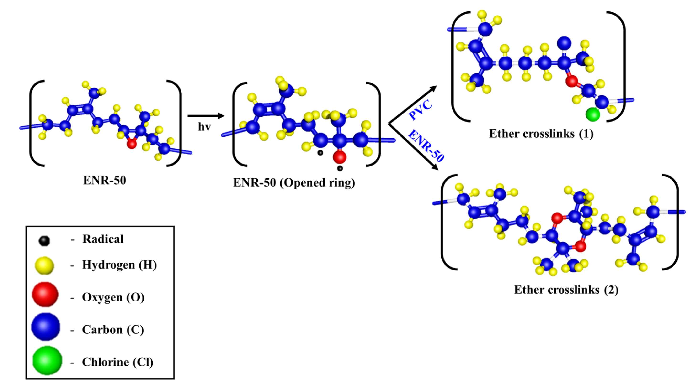
- Hamzah, R.; Bakar, M.A.; Dahham, O.S.; Zulkepli, N.N.; Dahham, S.S. A structural study of epoxidized natural rubber (ENR-50) ring opening under mild acidic condition. J. Appl. Polym. Sci. 2016, 133, 43. [Google Scholar] [CrossRef]
- Sabri, N.A.; Nawi, M.A.; Nawawi, W.I. Porous immobilized C coated N doped TiO2 containing in-situ generated polyenes for enhanced visible light photocatalytic activity. Opt. Mater. 2015, 48, 258–266. [Google Scholar] [CrossRef]


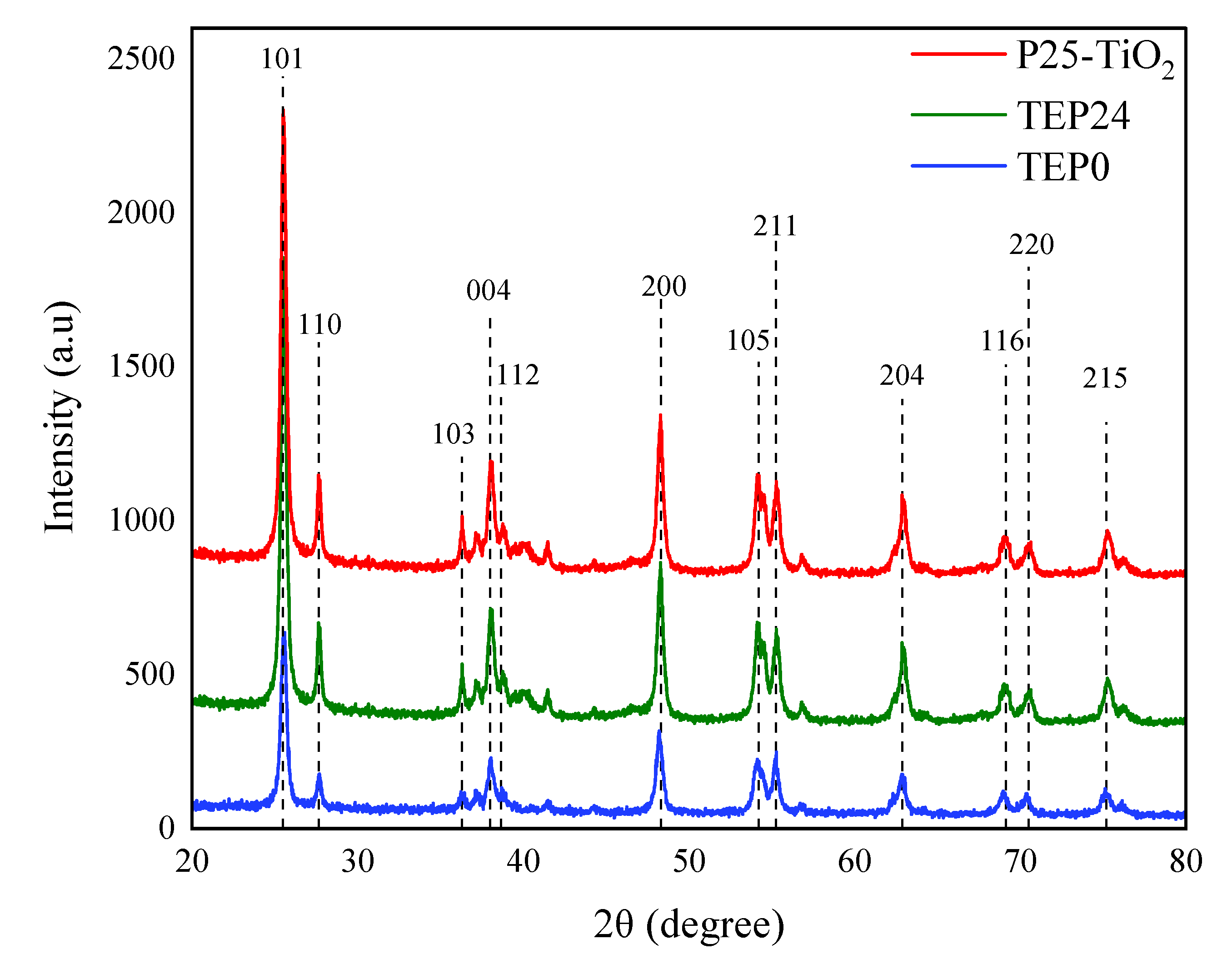
| Sample | Crystallinity Index (%) |
|---|---|
| TEP0 | 51.21 |
| TEP24 | 57.30 |
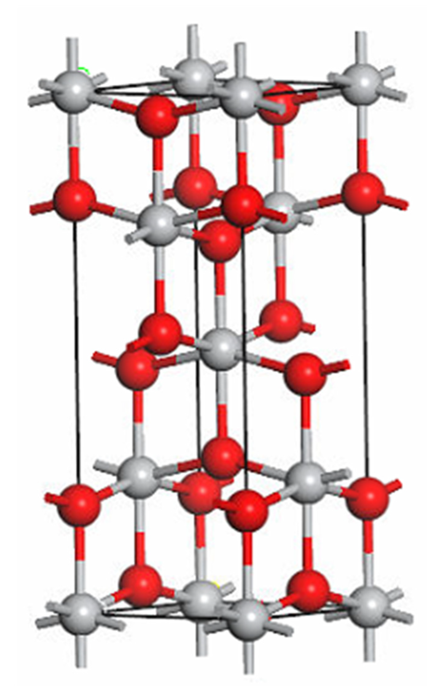
| Lattice Parameter (Å) | Volume (Å3) | Bond Length (Å) | ||
|---|---|---|---|---|
| TEP24 | a = 3.7752 | 136.4475 | Ti(1)-O | 1.9310 |
| b = 3.7752 | Ti(2)-O | 1.9861 | ||
| c = 9.5742 | O(1)-O | 2.4608 | ||
| O(2)-O | 2.7910 | |||
| TEP0 | a = 3.7758 | 136.3951 | Ti(1)-O | 1.93102 |
| b = 3.7758 | Ti(2)-O | 1.98602 | ||
| c = 9.5670 | O(1)-O | 2.46201 | ||
| O(2)-O | 2.79050 | |||
Disclaimer/Publisher’s Note: The statements, opinions and data contained in all publications are solely those of the individual author(s) and contributor(s) and not of MDPI and/or the editor(s). MDPI and/or the editor(s) disclaim responsibility for any injury to people or property resulting from any ideas, methods, instructions or products referred to in the content. |
© 2023 by the authors. Licensee MDPI, Basel, Switzerland. This article is an open access article distributed under the terms and conditions of the Creative Commons Attribution (CC BY) license (https://creativecommons.org/licenses/by/4.0/).
Share and Cite
Hamzah, S.R.; Rosli, M.A.; Natar, N.S.; Ghani, N.I.A.; Muhamad, N.A.; Azami, M.S.; Ishak, M.A.M.; Nordin, R.; Nawawi, W.I. The Crosslinking and Porosity Surface Effects of Photoetching Process on Immobilized Polymer-Based Titanium Dioxide for the Decolorization of Anionic Dye. Colorants 2023, 2, 73-89. https://doi.org/10.3390/colorants2010006
Hamzah SR, Rosli MA, Natar NS, Ghani NIA, Muhamad NA, Azami MS, Ishak MAM, Nordin R, Nawawi WI. The Crosslinking and Porosity Surface Effects of Photoetching Process on Immobilized Polymer-Based Titanium Dioxide for the Decolorization of Anionic Dye. Colorants. 2023; 2(1):73-89. https://doi.org/10.3390/colorants2010006
Chicago/Turabian StyleHamzah, Siti Raihan, Muhammad Afiq Rosli, Nadiah Sabihah Natar, Nureel Imanina Abdul Ghani, Nur Aien Muhamad, Mohammad Saifulddin Azami, Mohd Azlan Mohd Ishak, Razif Nordin, and Wan Izhan Nawawi. 2023. "The Crosslinking and Porosity Surface Effects of Photoetching Process on Immobilized Polymer-Based Titanium Dioxide for the Decolorization of Anionic Dye" Colorants 2, no. 1: 73-89. https://doi.org/10.3390/colorants2010006