
A Review of Fibre Reinforced Polymer Bridges


School of Architecture, Computing and Engineering (ACE), University of East London, 4-6 University Way, Beckton, London E16 2RD, UK
Fibers 2023, 11(5), 40; https://doi.org/10.3390/fib11050040
Submission received: 20 January 2023
/
Revised: 15 February 2023
/
Accepted: 22 March 2023
/
Published: 4 May 2023
(This article belongs to the Collection Review Papers of Fibers)
Abstract
:Fibre-reinforced polymer composites (FRPs) offer various benefits for bridge construction. Lightweight, durability, design flexibility and fast erection in inaccessible areas are their unique selling points for bridge engineering. FRPs are used in four bridge applications: (1) FRP rebars/tendons in concrete; (2) repair and strengthening of existing bridges; (3) new hybrid–FRP bridges with conventional materials and (4) all–FRP composite new bridges made entirely of FRP materials. This paper reviews FRP bridges, including all–FRP and hybrid–FRP bridges. FRP bridges’ history, materials, processes and bridge components—deck, girder, truss, moulded parts and cables/rebars are considered. This paper does not discuss the use of FRP as an architectural element and a strengthening system. While lack of design codes, material specifications and recycling are the major challenges, the high cost of FRPs still remains the most critical barrier to the progress of FRPs in bridges.
1. Introduction
Fibre Reinforced Polymer (FRP) composites have been used in decks and superstructure members of bridges since the 1970s [1,2,3,4]. The first pedestrian bridge is reported to have been built by the Israelis in 1975 [5]. FRP footbridges can be truss, cable-stayed or girder bridges [6]. The first all-composite vehicular bridge is Miyun Bridge, built in 1982 in Beijing, China [7]. Since then, many FRP pedestrian and road bridges have been constructed in Europe, China, Japan, and the USA. FRPs have various advantages for bridge engineering, such as lightweight, pre-fabrication, corrosion resistance, mouldability, fast installation in inaccessible areas and electrical insulation—glass FRP [8,9]. Although major impediments to the wider application of FRPs in construction are lack of design codes, material specifications and recycling, the high cost is still the main barrier to their widespread growth.
Construction represents 25% of global FRP production [10,11,12]. FRP contains fibres placed in a polymer resin matrix. Carbon and glass fibres are the most common fibres in bridges. Aramid fibres are sometimes used in cables of cable-stayed bridges. Basalt fibres are also being researched for potential use in bridges. Thermoset resins, such as polyester, vinylester or epoxy resins are used as matrices. Resins give shape to the fibres and protect them from environmental factors. Resin also sticks the fibres together and transfers forces between them. Fibres provide strength and stiffness to FRP parts [3,13,14,15,16,17].
Limited research publications have emerged in the last two decades on the review of FRP bridges. A book published in 2014 [18] on FRP bridges mainly relates to strengthening, repairing and retrofitting applications of FRP. It also covers FRP prestressing tendons and sheets, and cables. New hybrid–FRP bridges with conventional materials and all–FRP composite new bridges made entirely of FRP materials are not discussed in this book. Research papers are also available on specific bridge components or areas: highway decks—most of them dormant now [9,19,20,21,22,23,24,25], railway applications [26], girders [27] tendons [28,29] and cables [30,31,32,33]. From 2000 to 2010, a few review papers were written on all–FRP and hybrid–FRP bridges [4,34,35,36]. More recently, two papers in 2021–2022 [10,37] reviewed materials, methods and history of all–FRP bridges.
Most review papers [4,34,35,36] were published in the early 2000s. The FRP bridge industry has changed ever since and some FRP products have become dormant, in particular off-the-shelf vehicular decks and girders. This paper presents a state-of-the-art review of FRP bridges, mainly focusing on all–FRP and hybrid–FRP bridges. FRP composites in new-build bridges only are considered in this paper. FRP bridges often use moulded or pultruded FRP elements. Pultrusion is an automatic process for producing constant section profiles. Moulding is a manual method of fabricating complex sections virtually into any shape. Quite often, moulding leads to aesthetically pleasing bridge elements. The use of FRP in strengthening, retrofitting and repair of existing bridges made with steel or concrete is not discussed in this paper.
The aim of this paper is to present a historical perspective of materials, methods, structural form, fire performance, challenges and outlook for fibre-reinforced polymer bridges. This is presented in a review format. The use of FRP materials was quite popular during the 1980s and 1990s on several road and footbridges. However, FRP in road bridges has seen a decline in the last decade or so with many FRP parts becoming either dormant or no longer in use. The cost seems to be driving this change. The use of FRP in footbridges has seen growth though, mainly due to geometric possibilities that can be achieved using moulded FRP elements. The challenges and opportunities of FRP composites in bridges will also be among the key highlights of this paper.
The history of FRP bridges, including pedestrian and vehicular bridges, is presented in Section 2. FRP constituent materials and sandwich panel construction are examined in Section 3. FRP manufacturing methods are considered in Section 4, including automatic and manual processes. Various custom-made and standard FRP bridge components are reviewed in Section 5. The structural behaviour of FRP bridges under elevated temperatures and fire is reported in Section 6. Challenges and outlook for the use of FRP composite materials in bridge engineering are appraised in Section 7. Finally, the main conclusions are drawn in Section 8. Information about selected all–FRP and hybrid–FRP bridges constructed around the world is included in Appendix A.
2. History of FRP Bridges
Steel and concrete materials still dominate bridge construction. Fibre-reinforced polymer (FRP) materials provide an alternative to traditional materials in new bridges. Applications of FRP are in all–FRP or hybrid–FRP pedestrian and road bridges. In all–FRP bridges, the substructure (piers and abutments) is usually constructed using traditional materials. While the superstructure (decks, girder and cables) is made of FRP. In hybrid–FRP bridges, the main FRP components are girders, decks, external cables and parapet elements [36].
Prototype FRP composite bridges are believed to have been first conceived in Europe and North America around the 1970s. It is hard to establish when the first ever FRP bridge was constructed. The first all–FRP road bridge in the world, Miyun Bridge, was constructed in 1982 in Beijing, China. The bridge had a span of 20.7 m with six hand-laminated glass fibre/polyester sandwich girders. At the same time, the first hybrid–FRP bridge, Ginzi Highway Bridge, 11.9 m long was constructed in Ginzi, Bulgaria, in 1981/82. It used FRP composite beams and other bridge parts were constructed with traditional materials. Both bridges used energy and the labour-intensive hand lay-up method [8,36,38,39]. The major developments in FRP bridges happened in the 1990s when Aberfeldy Footbridge and Bonds Mill Lift Bridge were built in the UK and the No-Name Creek Bridge in the USA. Many FRP bridges were constructed after that using pultrusion, filament winding, wet or hand lay-up and resin infusion processes. In the following sections, selected examples of all–FRP and hybrid–FRP bridges are presented.
2.1. Examples of All–FRP Bridges
2.1.1. Aberfeldy Footbridge, Scotland, 1992
The Aberfeldy pedestrian bridge was the UK’s first major footbridge completed in 1992 in Scotland. This was a key development towards large-scale all–FRP bridge construction. The bridge connects two halves of a golf course on either side of the River Tay. The bridge comprised a GFRP deck, suspended by Parafil aramid ropes (cables) from two A-shaped GFRP towers. This cable-stayed bridge had a major span of 64 m, which was then believed to be the longest span in the world. It had an overall length of 113 m with a load capacity of 10 kN/m. Aberfeldy Footbridge was an all-composite bridge except for concrete foundations. The bridge was initially designed to carry pedestrians but later strengthened with CFRP to carry motorised golf buggies [4,34,38,40]. Structural health monitoring of the bridge was carried out by Stratford [41] after 20 years of service. Figure 1 shows Aberfeldy Footbridge.
2.1.2. Bonds Mill Lift Bridge, UK, 1994
Lightweight FRP offers great benefits when moveable bridges are required. The lifting machinery is significantly reduced with the lightweight components of the bridge [40]. Bonds Mill Lift Bridge, shown in Figure 2, was the first UK all-composite road bridge, installed in Gloucestershire in 1994. This 8 m single bascule bridge provides access to a private industrial estate for heavy trucks over the Thames–Severn canal. The bridge used the same cellular pultruded GFRP system—Advanced Composite Construction System (ACCS) as in Aberfeldy Footbridge. To resist local bending under wheels, the upper portion of the cellular system was filled with structural foam. The bridge was designed to carry full highway loading including a 38-tonne truckload. After eight years of service, an inspection was carried out by Hollaway [43] with no deterioration in GFRP. However, there was a wearing surface at the south end of the bridge due to the impact of lorries running at a steep slope from the industrial estate [8,40,43].
2.1.3. No-Name Creek Bridge, USA, 1996
No-Name Creek Bridge is the first all–FRP composite road bridge in the USA. This 8 m span bridge was built in 1996 in Russel, Kansas, by Kansas Structural Composites. It consisted of a sandwich deck with GFRP laminated skins and a honeycomb core. It is a single-span bridge supported on steel abutments. Static and fatigue field tests were carried out on the bridge in 1997, 2004 and 2008 to investigate the environmental degradation of FRP material [44].
2.1.4. Kolding Bridge, Denmark, 1997
Kolding Bridge, Denmark (Figure 3) is the first FRP footbridge over a busy railway line. The cable-stayed bridge was constructed completely of glass fibre-reinforced polymer in 1997. This 40 m-long footbridge had two spans of 27 m and 13 m. The bridge had 100 × 100 mm square hollow tube GFRP cables, a 1.5 m deep girder and 18.5 m pylons made of standard FRP profiles. The bridge weighed 12.5 tonnes, half of the steel alternative, and was installed in 18 h [45]. Kolding Bridge is an all–FRP bridge, except for abutments at the foundations; and bolts are made of stainless steel [46].
2.1.5. Pontresina Truss Footbridge, Switzerland, 1997
Pontresina Truss Footbridge is a 25 m long all–FRP temporary footbridge constructed in Pontresina Switzerland in 1997, shown in Figure 4. The bridge crosses Flaz Creek in the Swiss Alps at an altitude of 1790 m. This temporary bridge is mainly used in winter for ski tourism. During summer, the bridge is removed due to the potential risk of high water and is stored on the bank. Each year the bridge is installed in the autumn and removed in the spring. The bridge used five different types of pultruded GFRP profiles assembled into two multi-layer truss girders connected by cross beams and stabilised by the bracing. It has two 12.5 spans with bonded joints in one span and bolted in the other [36,47,48].
2.1.6. Halgover Footbridge, UK, 2001
Halgover Footbridge shown in Figure 5 is the first bridge using a different processing method than pultrusion. The bridge was installed in 2001 over the A30 in Cornwall, UK. This 47 m span suspension bridge used resin-infused glass FRP decking [49]. Later in 2015, a geometrically nonlinear static and dynamic analysis of the bridge was carried out by Gunaydin et al. [43] and the results of this all–FRP bridge were compared with an identical steel bridge.
2.1.7. Lleida Footbridge, Spain, 2001
Lleida Footbridge is a double-tied arch bridge spanning 38 m over a high-speed train line between Madrid and Barcelona in Spain. The bridge used Fiberline profiles [46], as seen in Figure 6. It was completed in 2001 and officially opened in 2004. The arches and bridge deck girders used rectangular hollow sections. All joints were bolted using stainless steel bolts and brackets [50]. The bridge weighed 19 tonnes and all profiles used E-glass fibres with polyester resin. It was designed for a 4 kN/m2 serviceability load as per Spanish bridge design codes. The partial safety factors for materials to verify ULS were 2 and 3 for normal and shear stresses. The design was mainly controlled by deflection with some elements of arches, where buckling stability governed [39].
2.1.8. West Mill Bridge, UK, 2002
West Mill highway bridge seen in Figure 7 was constructed over the River Cole near Shrivenham in Oxfordshire, UK in 2002. It was the first all–FRP road bridge in Western Europe, incorporating glass and carbon fibre-reinforced composites. The bridge span was 10 m and the width was 6.8 m. The bridge contained four 10 m GFRP box beams stiffened by CFRP flanges. A total of 34 GFRP ASSET deck profiles (transverse) were bonded to these beams. The bridge used reinforced concrete abutments and reinforced concrete parapet beams with steel parapets [34,51]. Structural health monitoring and repair of the bridge were carried out by Canning et al. [52] and Sebastian et al. [53].
2.1.9. Fredrikstad Bascule Footbridge, Norway, 2003
The Fredrikstad pedestrian bascule FRP footbridge in Norway was the first moveable lifting bridge in Europe. The bascule footbridge is shown in a closed state in Figure 8a and an open state in Figure 8b. This 60 m long and 3 m wide pedestrian bridge was completed in 2003. The bridge did not have any counterweights to operate the opening mechanism. Instead, it had a large hydraulic cylinder at each side to lift the bridge. By using FRP material the weight of each moveable part was reduced to 20 tonnes, with FRP elements weighing 9 tonnes. The bridge uses double-curved boxed girders with longitudinal and transverse stiffeners inside. The deck is a sandwich structure with CFRP reinforcements and a balsa core. All FRP parts, except side panels, were manufactured by vacuum-assisted resin infusion [54,55].
2.1.10. St Austell Railway Bridge, UK, 2007
St Austell Railway Bridge was installed over the Paddington–Penzance railway line near St Austell station, Cornwall, UK in 2007. The front and side view of the bridge is given in Figure 9a,b, respectively. This all–FRP footbridge replaced an old corroded wrought-iron bridge built in the early twentieth century. It used the same FRP cellular system (ACCS) as in Bonds Mill and Aberfeldy FRP bridges. The bridge had three simply supported spans, with a main span of 14 m and two side spans of 6 m each. The main 14 m span weighted just 5 tonnes replacing the 26 tonnes old structure. It had a U-shaped cross-section made from pultruded FRP elements with an outer FRP moulded shell. The bridge had to be supported on existing masonry piers and abutments. This bridge is designed for a standard footbridge loading of 5 kN/m2. It was fabricated off-site and installed in only eight hours [26,56,57].
2.1.11. ApATeCh Arched Footbridge, Russia, 2008
ApATeCh arched footbridge (seen in Figure 10) is an all-composite bridge installed by ApATeCh [58] in Moscow Russia in 2008. Except for metal hinges and fence fasteners, all parts are made of FRP composites. The bridge had a central arch and two beams. It is 22.6 m long, 2.8 m wide and weighs just 4.5 tonnes. The bridge was the first FRP bridge in Russia made by the vacuum infusion process. Using vacuum infusion reduced assembly and manufacturing time resulting in low cost. This production technology improved aesthetic possibilities with new pleasing structural forms.
2.1.12. Bradkirk Footbridge, UK, 2009
Bradkirk Footbridge is one of the first few bridges using moulded FRP composites and is shown in Figure 11. This all–FRP bridge was installed near Kirkham in Lancashire over the Preston–Blackpool North Line. The bridge contained two 12 m spans with a staircase at each end. Each span weighed just two tonnes. The bridge installation was completed in just six hours overnight. The moulded FRP composite used two layers of woven E-glass cloth with resin in between them. Then, a vinylester tie coat was applied with a polyester gelcoat. The material was then placed in the mould, bagged and cured at 70 °C [59]. Halgavor footbridge also used the same moulding process [8]. The structural health monitoring system was used to measure the effect of train buffeting on the dynamic behaviour of the bridge [59].
2.1.13. Dawlish Footbridge, Exeter, Devon, UK, 2012
Dawlish Footbridge was constructed in 2012 at Dawlish train station in Exeter, South Devon, UK. The new FRP bridge is shown in Figure 12a. The bridge replaces the old, corroded steel bridge built in 1937 seen in Figure 12b. On completion, Dawlish bridge became the first Grade II listed FRP bridge. It uses standard pultruded FRP profiles using bonded and bolted joints, sandwich parapets made by film infusion and moulded FRP stair elements. The bridge has a span of 17.5 m and the walkway is 1.8 m wide. Due to its proximity to the beach, the bridge is constantly exposed to coastal erosion and salt spray-induced corrosion. The all–FRP bridge was proposed to reduce maintenance cost, and installation time and withstand the hostile coastal environment. The new FRP bridge replicated the form of the old steel bridge [60].
2.1.14. Pont y Ddraig Bridge or the Dragon’s Bridge, Wales, 2013
Pont y Ddraig Bridge or the Dragon’s Bridge is a double bascule FRP footbridge as shown in Figure 13a in a lowered position and Figure 13b in a raised position. The bridge was installed at Rhyl Harbour, North Wales in 2013. It contains two mirroring 30 m long decks connected to a central stainless-steel tower with lifting cables. The bridge deck can be lifted by the cables for navigation purposes. It combines glass and carbon resin-infused FRPs. The deck is curved in both plan and elevation. Each deck span weighed 10.6 tonnes. The deck used mainly glass fibre sandwich shells with carbon fibre unidirectional longitudinal plates at highly stressed regions. It also used Corecell M-Foam as core material and Ampreg 21 resin. The lightweight of the bridge enabled two composite decks or dragon wings to be raised [8,61,62].
2.1.15. Eindhoven University of Technology Pedestrian Bridge, The Netherlands, 2016
Eindhoven Pedestrian Bridge is a bio-composite footbridge over the river Dommel in Eindhoven, The Netherlands. The bridge shown in Figure 14 was completed in 2016. This 14 m span and 1.2 wide bridge was designed and installed within a year. The structural elements in the bridge used a mix of hemp and flax fibres in epoxy resin with a 56% fibre volume fraction. The non-structural parts employed an aliphatic thermoplastic polyester made of renewable resources. The bridge deck had a rectangular cross-section near abutments and a nearly triangular section in the middle. To facilitate this geometry the vacuum-assisted resin infusion process was used to produce the bridge.
The railings of the bridge also used bio-composite material and resembled grass cutters. The Fibre Brag sensor technique was used to embed sensors in the bridge for structural health monitoring [63]. The data was monitored by Blok et al. [63] in their paper continuously for two years. The sensors applied to the woven flax material on the tension side proved to be successful and gave reliable results until the writing of their paper in 2019. The sensors embedded in non-woven hemp fibre composite on the compression side failed after initial readings. This bridge is an excellent example of using eco-friendly sustainable bio-based materials for structural elements.
2.1.16. Dover Sea Wall Footbridge over a Rail Line, Dover, Kent, UK 2017
The storms of 2015 completely damaged the existing steel footbridge near Dover Sea Wall, Dover, Kent, UK. The steel bridge was replaced with a hybrid–FRP bridge with pultruded and resin-infused parts, as shown in Figure 15. The bridge deck, top chords and anti-slip phenolic wear plates for stairways were resin infused. On the other hand, the truss members, landings, stairwell and parapet were fabricated from pultruded FRP profiles and plates. The sections were prefabricated, and the completed bridge was 31 m long and 2.415 m wide. It consisted of two simply supported 14.5 m bridge spans over concrete abutments with one span on top of the railway track. The bridge design life was for 120 years. The bridge weighed about a third of its steel equivalent [8]. Human-induced vibrations, dynamic properties and serviceability of the bridge were studied in a recent paper by Russell et al. [64].
2.2. Examples of Hybrid–FRP Bridges
Hybrid–FRP bridges have been used for the past 20 years. FRP composites can be used in combination with traditional materials, such as steel and concrete. Main examples of these bridges include road bridges with CFRP girders with concrete slabs on top and supported on concrete piers. Another common example relates to an FRP deck supported by steel or concrete girders or steel cables. In the sections to follow, real-life examples of hybrid–FRP bridges are described.
2.2.1. Asturias Bridge, Spain, 2004 (Hybrid–FRP Beam—Concrete Slab)
Asturias Bridge, seen in Figure 16, is the first FRP vehicular bridge constructed in Spain in 2004. It is a four-span bridge with CFRP girders supported on three intermediate supports. The length of the bridge is 46 m with two middle spans of 13 m and two end spans of 10 m. The concrete slab was supported on a permanent GFRP formwork, which was connected to the CFRP girders underneath. A polyurethane mould was wrapped by CFRP prepregs to produce the girder. The girder was a trapezoidal box section with a 1.2 m top flange, 0.8 m bottom flange and 0.8 m web. The core of the box girder was filled with polyurethane [27,65]. To validate the serviceability and ultimate load capacity limits of the 46 m long bridge, the 13 m full section of the bridge was tested in the laboratory by Gutiérrez et al. [66].
2.2.2. M111 Bridges, Madrid, Spain 2007 (Moulded FRP Girders and Concrete Deck)
The M111 twin bridges are located near Madrid, Spain along the M111 motorway (shown in Figure 17). Built in 2007 by Acciona construction, Spain, the bridges had three simply supported spans of 10, 14 and 10 m and a 20.4 m wide box girder deck. The deck slab is supported by four FRP girders. The girder had a reverse omega shape. Its top and bottom flanges are made of hybrid carbon and glass fibre laminates. The girder webs consist of sandwich panels having glass fibre skins and a polyurethane core [27,65,67].
2.2.3. Standen Hey Overbridge, UK, 2007 (Deck)
Standen Hey Overbridge was installed by Network Rail, UK. It is a built-up bridge deck made of all–FRP pultruded panels in 2007 near Clitheroe, Lancashire. This was perhaps the UK’s first purpose-built deck for a road bridge. The bridge had a clear span of 9.5 m with 3 m wide single-lane rural road access (see Figure 18). The deck was designed using ASSET profiles consisting of two triangular cells creating a rhombus shape. The ASSET profiles were produced in Denmark and transported in required lengths to the UK. The original bridge had cast-iron beams supporting a timber deck. The new FRP bridge deck had double layers of ASSET profiles and a third layer to act as a plinth for the parapet. The deck was installed in the standard 8 h rail closure [26]. Each profile was 225 m deep and 300 mm wide, and the webs were inclined at 60° to the horizontal. The profiles were bonded with epoxy adhesive. The 10 m long built-up deck weighed 20 tonnes, spanned between original abutments and was supported on new precast concrete beams. The deck used E-glass fibres in the form of bi-axial mats [69]. A similar deck with a single layer was used on Klipphausen Bridge, Germany [8].
2.2.4. Gądki Footbridge, Poland 2008 (Deck)
Built in 2008, Gądki Footbridge is located over road no. 11 (Poznan—Kornik expressway) in Gądki, Poland. This hybrid steel arch bridge has FRP composite deck in the main central span, and steel–concrete composite and reinforced concrete access spans (see Figure 19). The complete bridge is 260 m long. The main span containing the FRP deck has in-plane curved girders supported by an inclined arch. The 40 m span main arch girder was a steel pipe section with 1200 mm diameter and 16 mm wall thickness. The deck girder was a 660 mm diameter and 20–30 mm thick steel pipe section. The deck is curved with an 80 m radius and the walkway is made of pultruded FRP profiles. The footbridge is supported on spot footing and the main arch is supported on prefabricated reinforced concrete piles [23].
2.2.5. Moss Canal Bridge, UK, 2011 (Deck)
The use of the largest FRP profile as a deck on Moss Canal Bridge, Rochdale, UK was a step change for FRP bridges in 2011. The original bridge with in-situ concrete portal frame is shown in Figure 20a and the new FRP bridge is seen in Figure 20b. The FRP profile was a double web beam about 900 mm deep and 450 mm wide. The bridge was 12 m long and 3 m wide. The FRP deck used multi-axial pultruded sections of E-glass fibres in vinylester resin to support the 9 m bridge span. The deterioration of the existing reinforced concrete deck required deck replacement. Again, the lightweight of FRPs reduced both installation and fabrication costs [72].
2.2.6. St. Mateus—GFRP–Steel and São Silvestre Footbridges, Portugal 2013
St. Mateus Footbridge is a GFRP–steel hybrid footbridge constructed in Viseu, Portugal. This represents a typical GFRP deck combined with a steel girder. The span of the bridge was 13.3 m and the width was 2.5 m. The GFRP slab was fabricated using thin-walled multicellular deck panels. Experimental, numerical, and analytical study of St. Mateus Bridge is presented in papers [73,74]. São Silvestre Footbridge is a 10.5 m span hybrid bridge in Portugal constructed using pultruded GFRP profiles and a very thin concrete deck made of steel fibre-reinforced self-compacting concrete (SFRSCC) pre-cast slabs. The prototype of the bridge with a 5.5 m span was tested in a laboratory by Gonilha et al. [75].
2.2.7. Mapledurham Footbridge, UK, 2015 (Deck)
Mapledurham Footbridge was a replacement bridge, which was installed on the river Thames in Mapledurham, Oxfordshire, UK in 2015. This 13 m bridge uses a sandwich system with GFRP skin and foam core. Due to limited access to the site, the bridge was floated to the site on a barge along River Thames as shown in Figure 21a and the installed FRP bridge, with no physical joints, is seen in Figure 21b. The bridge span was fabricated as a single unit. The FRP bridge decks were one-third the weight of equivalent steel or concrete slabs. The prefabrication and lightweight of FRPs allowed easy transportation of the bridge on a freight boat [8].
2.2.8. Sedlescombe Footbridge, UK, 2015 (Deck)
Sedlescombe Footbridge was installed in Sedlescombe village in East Sussex, UK to replace an existing timber bridge in 2015, as shown in Figure 22. The lightweight, quick installation time, low maintenance and whole-life cost controlled the design. The bridge was designed for 60 years. The bridge used a resin-infused FRP composite deck with powder coated steel parapet. It was 8 m long and 1.35 m wide, and the depth of sections was 250 mm. The bridge weighed only one tonne compared to the four-tonne original timber bridge [8].
3. FRP Composite Constituent Materials
FRP composites contain fibres embedded in a resin matrix. The fibres provide strength to the FRP part. The resin matrix provides shape, protects fibres and transfers force [1,2,3,13,76,77].
3.1. Fibres
Synthetic fibres, such as glass, carbon and aramid fibres are used in bridge applications. These fibres are the main load-bearing elements in an FRP composite system. The typical properties of plain fibres are presented in Table 1. The tensile strength of a finished FRP product, which includes plain fibres embedded in a resin matrix, will be much less than the strength of plain fibres. The behaviour of these fibres is linear–elastic under tensile loading up to failure [7]. Aramid fibres exhibit nonlinear ductile stress–strain response under compression [78]. Tensile stress–strain curves for carbon, glass and aramid fibres are shown in Figure 23.
3.1.1. Glass Fibres
Glass fibres dominate the FRP composite market in civil engineering. More than 90% of all commercial FRP products use glass fibres [80]. E-glass formulation (for electrical grade) is the most widely used form of glass fibres. Almost 80–90% of all commercially produced glass is E-glass [81]. Glass FRP was used in No-Name Creek Bridge in the USA in 1996. The bridge used a sandwich deck with GFRP laminated outer skins and a honeycomb core [44]. Glass fibre-reinforced cables and pultruded profiles were also used in Kolding cable-stayed footbridge in Denmark. The bridge had two girder spans and a pylon. This 40 m footbridge was fabricated by Fiberline in 1997 and was believed to be the first pedestrian overpass over a busy railway line [45,46]. Lleida Footbridge, Spain also used pultruded GFRP profiles with polyester resin in 2001. The structural form of the bridge was a double-tied arch mechanism [39,50]. Halgover Footbridge, UK used resin-infused glass FRP decking in 2001. This was the first use of any other manufacturing method rather than pultrusion [49]. In 2002, West Mill Bridge, UK used GFRP box beams stiffened by CFRP flanges and GFRP ASSET deck profiles bonded to these beams [34,51].
3.1.2. Carbon Fibres
Carbon fibres have the highest tensile strength and Young’s modulus among all synthetic fibres. The main reason for using carbon fibres in bridge applications is their high tensile modules—comparable to structural steel. In addition, carbon fibres have high fatigue, creep and chemical resistances [13]. Carbon fibres are suitable for chemically ingressive and other harsh environments. Carbon fibres are at least 10–30 times more expensive than E-glass fibres [1,82,83]. Different grades of carbon fibres and their properties are given in Table 1. The high modulus reduces the tensile stress and strain, making it a brittle material [84].
Carbon FRP cable strands were first used as tensioning materials in a prestressed concrete bridge in the USA in the late 1980s [85]. West Mill Bridge, UK (2002) was an excellent example of combining carbon and glass fibres. GFRP box girders with CFRP flanges were used in the bridge [34,51]. Pont y Ddraig Bridge, Wales (2013) is yet another instance where carbon and glass resin-infused FRPs were used. The deck used glass fibre sandwich shells with carbon fibre unidirectional longitudinal plates [8,61,62]. The M111 twin road bridges in Spain (2007) used girders with hybrid glass and carbon laminates and the web used sandwich panels with glass fibre skins and polyurethane core [65]. Fredrikstad Bascule Footbridge, Norway (2003) used a sandwich deck with carbon fibre skins and a balsa core [54]. Asturias Bridge, Spain (2004) used CFFP box girders with polyurethane core. The girders supported the permanent GFRP formwork for the concrete slab [66]. Carbon fibres were also used to strengthen Aberfeldy Footbridge, Scotland (1992) for supporting motorised golf buggies [34].
3.1.3. Aramid Fibres
Aramid fibres (Kevlar or Twaron fibres) are rarely used in engineering applications. They are mainly used in FRP rebars, prestressing tendons, and cables in bridges [86]. Aramid fibres show good toughness, creep, fire resistance, damage tolerance and tensile fatigue properties [78]. The main weakness of aramid fibres is their low compressive strength (500–1000 MPa); their compressive strength being less than 20% of their tensile strength (2800–4100 MPa). Aramid fibre–Kevlar 49 exhibits brittle linear elastic stress-strain behaviour in tension. However, it behaves in a nonlinear ductile manner under compressive load resulting in high energy absorption. It also gives a plastic behaviour in compression when subjected to bending. This type of behaviour increases the impact resistance of aramid fibres [2,78,82]. Due to lower compressive strength (only 20% of the tensile strength), a cautious approach must be taken when using aramid fibres as a compression or flexural reinforcement [8]. Aramid fibres are only used in applications where tensile forces are dominant, such as tension cables in cable-stayed bridges.
Aramid fibres are used as tendons in prestressed concrete, and cable stays in bridges and ropes in the marine industry due to their high tensile strength and corrosion resistance [87]. The use of aramid rods for prestressing began in the early 1980s in the Netherlands as pultruded flat strips and round bars [40]. Aramid FRP prestressing tendons were used in the deck of a stressed ribbon pedestrian bridge near Tokyo, Japan in 1991 [86]. The Parafil aramid rope (cable) system was developed in the 1970s for mooring offshore platforms and stabilising large radio antennae [40]. Aberfeldy Footbridge, Scotland (1992) used the Parafil aramid ropes (cables) connected to two A-shaped GFRP towers and supported a GFRP suspended slab [34]. The Parafil rope system was also used as a tension tie in the Oppegaard tied arch footbridge in Norway. The bridge is built on a golf course crossing a small stream [40].
3.2. Resin Matrix
The matrix contains polymer resin and other additives and fillers. The resin glues the fibres and protects them from environmental factors. It transfers forces between fibres and prevents the buckling of fibres under compression. The matrix constitutes 30–60% by volume of the FRP part [82]. There are two types of polymer resins: thermosetting resins and thermoplastic resins. The properties of thermosetting resins are presented in Table 1. At its glass transition temperature (Tg, °C), amorphous polymers undergo a change from a hard to a soft or rubbery state. A unidirectional FRP composite component’s glass transition temperature is often taken as equal to a resin’s glass transition temperature [2].
3.2.1. Thermoset Resin
Thermoset resins are most commonly used in structural FRP products [82]. Thermoset resins contain five types: polyester, epoxy, vinylester, phenolic and polyurethane. Their molecules are connected by strong bonds. Once cured, they cannot be remoulded to other shapes. Placing fibres in these resins is easy due to their low viscosity. Most FRP parts use polyester resins; this is roughly 75% of FRP composites [13].
Epoxy resins can also be used as a matrix in an FRP part or as a binder to connect two FRP products. Epoxy is used in FRP tendons, cables, and strengthening applications. The high cost and processing difficulty due to high adhesion makes epoxy unsuitable for FRP profiles [1]. Epoxy resins offer the best adhesive bonding properties. Polyester resins have the least bonding ability. High adhesion properties make epoxy resin suitable for the fabrication of sandwich panels with a honeycomb core [8]. Phenolic resins are the oldest resins with good fire resistance. Their use is limited due to problems in reinforcing and curing them [3]. Polyurethane resins offer high toughness resistance. Using them with glass fibres can produce high-impact and tensile-resistant FRP composites [1].
3.2.2. Thermoplastic Resin
Thermoplastic resins have four categories: polypropylene, polyamide, polyethylene and polybutylene. Due to weak molecular bonds, thermoplastic resins can be moulded, remoulded, and reshaped. By exposing them to temperatures higher than their forming temperature, they can be repeatedly softened and hardened. They can also be easily recycled. Due to their sticky nature, fibre impregnation is very hard, and this leads to the higher costs of FRPs. They are mainly used in aerospace applications [3,88]. Polyethylene thermoplastic resins were first used in the 1990s in the USA. The first bridge that used high-density polyethylene (HPDE) thermoplastic resin was built at Fort Leonard Wood, Missouri, USA. Thermoplastic composite I-beams were used as main girders in a vehicular bridge built in Wharton State Forest, New Jersey, USA in 2002, In 2009, two bridges were built at Fort Bragg, North Carolina, USA using thermoplastic resin composite with glass fibres. The world’s first thermoplastic-based all–FRP composite railroad bridge was built at Fort Eustis, Virginia, USA in 2010 [89]. Despite this limited use in bridges, thermoplastic-based FRPs are rarely used in structural applications [8].
3.3. Laminated Shells and Sandwich Panels
Freedom of geometry allows FRP bridge elements to be moulded into any shape. The moulded shapes can be realised by either laminated shells or sandwich panels. Several FRP bridges, Halgavor Bridge [49], Bradkirk Footbridge [59], Pont y Ddraig Bascule Bridge [62], Purfleet Footbridge [10], Sedlescombe Footbridge [8] and Mapledurham Bridge [8] used sandwich panels and laminates. Laminated shells consist of single-skin laminations and sandwich panels containing a core (foam, wood or honeycomb) enclosed by adhesively bonded outer skins or laminates. The skins or face sheets are usually glass or carbon fibre-reinforced polymer laminates. Mechanical properties of both laminated shells and sandwich panels are obtained by testing the individual plies from coupon testing. Panel, core and beam failure modes must be considered when designing sandwich panels [8].
4. Manufacturing Methods
The main materials used in fibre-reinforced polymer composites include fibre reinforcement layers, the resin matrix, and the core in the case of sandwich construction. Fibre reinforcement layers can be dry (without resin), wet (with resin) or prepreg reinforcing layers with partially cured resin [8]. The advantages, disadvantages, applications, and materials used for different FRP manufacturing methods are presented in Table 2.
4.1. Spray Lay-Up (Contact Moulding)
The method consists of a hand-held spray gun directed into a mould. The fibres are chopped in the gun and fed into the resin spray of the gun. The mould is treated with mould release and a gel coat is applied. Then, the catalysed resin and fibres are sprayed into the mould. The resulting laminate is compacted with hand rollers. This method is only limited to polyester resin and glass fibres. Fibres must be short, and the resin should have low viscosity. If required, the core material, such as wood or foam is added, and a second spray layer is applied. In this way, the core is embedded between two laminate skins. The composite part is then cured, cooled, and removed from the mould [90,91]. The schematic diagram of the spray lay-up is shown in Figure 24.

Table 2.
Applications, strengths, weaknesses, and material options for different manufacturing methods [92].
Table 2.
Applications, strengths, weaknesses, and material options for different manufacturing methods [92].
| Method | Material | Applications | Strengths | Weaknesses | ||
|---|---|---|---|---|---|---|
| Resin | Fibre | Core | ||||
| Spray lay-up (contact moulding ) | Mainly polyester | Glass roving only | None. To be added separately |
|
|
|
| Wet or hand lay-up (contact moulding) | Any resin, epoxy, polyester, vinylester, pnolic | Any, heavy aramid fibres hard to wet-out | Any |
|
|
|
| Vacuum bagging—wet lay-up (moulded) | Mainly epoxy and phenolic Polyester resin will have problems due to the extraction of styrene by the vacuum pump | A variety of heavy fabrics can be wet-out | Any |
|
|
|
| Filament Winding | Any resin, epoxy, polyester, vinylester, phenolic | Any, straight fibres used, not woven or stitched | Any, usually used for single-skin elements |
|
|
|
| Pultrusion | Epoxy, polyester, vinylester, phenolic | Any | Not used |
|
|
|
| Resin transfer moulding, RTM (moulding) | Epoxy, polyester, vinylester and phenolic | Any, stitched fabrics allow resin flow | No honeycomb |
|
|
|
| Other methods—SCRIMP, RIFT, VARTM, resin film infusion (moulded) * | Epoxy, polyester and vinylester | Any stitched fabrics | Any except honeycomb |
|
|
|
| Prepreg—autoclave | Epoxy, polyester, phenolic and other high-temperature resins | Any | Special foam due to high temperature and pressure |
|
|
|
* SCRIMP = Seemann Composites Resin Infusion Moulding Process, RIFT = Resin Infusion under Flexible Tooling, VARTM = Vacuum Assisted Resin Transfer Moulding.
4.2. Wet or Hand Lay-Up (Contact Moulding)
Hand or wet lay-up is the most basic process. It consists of stacking either dry fabrics in the resin system or prepregs (fibre system pre-impregnated with resin) to form a laminate stack. The part is then allowed to cure and takes the shape of the mould. The curing is at room temperature, no extra heat is required. This manual method can either be used onsite or offsite. For bridge applications, FRP components are usually fabricated offsite. Although hand lay-up is a reliable method, it is more time-consuming than other methods, as each ply is handled only by hand. Any fibre system in any form (chopped, woven, continuous) is suitable for this method. Brushes and rollers are generally used to apply the resin and reduce air bubbles [13,90,91]. Miyun Bridge, in Beijing, China and Ginzi Highway Bridge in Bulgaria used the hand lay-up method [8,36,38,39]. The diagram in Figure 25 shows the process of hand or wet lay-up.
4.3. Vacuum Bagging—Wet Lay-Up (Moulded)
The vacuum bagging process is similar to wet lay-up except the pressure is applied to compact laminate layers [91]. The prepreg or fibre-resin system is staked to the desired thickness before covering it with a film layer, air breeder/breeder fabric and vacuum bagging film. This process uses a vacuum to remove excess resin and trapped air from the mould. It also gives better adhesion and concentration between layers [90]. The vacuum bagging is most suited to epoxy and phenolic resins. Polyester and vinylester resins can have problems due to the excessive removal of styrene from the resin by the vacuum pump. Styrene is a substance present in resin and up to 50% of that helps them reduce the viscosity and allows them to cure [92]. Consumable materials and equipment required for vacuum bagging are described in [92]. The illustration of vacuum bagging method is presented in Figure 26.
4.4. Filament Winding
The filament winding process produces hollow circular or oval parts. The diagram in Figure 27 shows the filament winding process. It is highly automated and repeatable, and relatively inexpensive. The mould for this process is a rotating mandrel, an open mould. The mandrel is a long cylindrical tool on which fibres are wound. The process is similar to pultrusion where fibres are pulled through the resin bath [90]. The head travels along the rotating mandrel winding fibres on it in a specified configuration. The fibres are distributed equally throughout the length of the mandrel [91]. The fibres from the creel just pass through a resin bath before winding on the mandrel. Thermoset serin and straight fibres from creel (no stitched or woven fabric) are used in this method. After autoclave curing, the mandrel is either removed or becomes a permanent part of the finished product. The method is usually used with polymer matrices and synthetic fibres. The prepreg material can also be used in which case the fibres are wound without resin–dry winding [91,92]. Filament winding is used in hollow circular profiles in bridges.
4.5. Pultrusion
Pultrusion is an automatic and continuous process for producing constant section FRP parts. It is the most cost-competitive process for fabricating profiles, rebars and strips for structural engineering applications [2,93,94]. Fibres are pulled from creels via a resin bath and fed into a heated die. Fibres, continuous filament mat (CFM) and surface are passed though guide plates before the resin bath. The guide plates give a predetermined shape to the profile. I-beam, wide-fanged sections, channels and multicellular profiles can be produced by pultrusion [3,13,21]. The die controls the resin content and cures the material to its final shape. The finished profile is automatically cut to length. Figure 28 represents schematically the pultrusion process.
Unidirectional fibres (rovings) give strength along the length of the profile and fabric mats provide strength in the transverse direction. Polyester surface veils are used for protection and finishing [92]. Examples of pultruded elements in bridges include Aberfeldy Footbridge, Scotland [4,34,38,40], Bonds Mill Lift Bridge, UK [8,40,43], Pontresina Truss Footbridge, Switzerland [36,47,48], St Austell Railway Bridge, UK [26,56,57], Dawlish Footbridge, UK [60], Dover Sea Wall Footbridge, UK [8], Standen Hey Overbridge, UK using a double layer of ASSET profiles [26], Gądki Footbridge, Poland [23], Moss Canal Bridge, UK [72] and many other bridges presented in Section 2.
4.6. Resin Transfer Moulding, RTM (Moulding)
The resin transfer moulding (RTM) method produces complex geometries at reasonably high production rates. It contains two moulds with a fibre mat and resin pressed in between them. The moulds are made of either composites or steel. Due to the closed mould arrangement, the final product has finished surfaces on both sides [90]. Dry fabric layers are first laid at the bottom of the mould. The fabrics are held together by the binder or they are pre-pressed into the mould. The top mould is then clamped to the bottom and the cavity is filled with the resin. Sometimes vacuum is used to pump resin into the fabrics. This process is termed Vacuum Assisted Resin Injection (VARI). The resin inlets are closed after all the fabric has been wetted out, and the laminate is left to cure at either ambient or elevated temperature [92]. The resin transfer moulding process is represented schematically in Figure 29.
4.7. Other Methods—SCRIMP, RIFT, VARTM, Resin Film Infusion (Moulded)
Vacuum infusion moulding, vacuum assisted resin infusion or Vacuum Assisted Resin Transfer Moulding (VARTM), Seemann Composites Resin Infusion Moulding Process (SCRIMP) and Resin Infusion under Flexible Tooling (RIFT) are recently developed FRP composite manufacturing methods. In these, a vacuum is used to draw resin into a fibre system placed on a mould covered with plastic bagging film. These processes are more suitable for large mouldings, such as wind turbine blades, all–FRP bridges, car body shells and boat hulls [95]. The VARTM process is shown in Figure 30.
In these methods, dry fabrics are stacked in a one-sided mould in the same way as in RTM. Next, the stacked fabrics are covered with peel ply and a knitted type of non-structural fabric. Vacuum bagging is then applied to the whole dry stack, and after bag leaks have been removed, the resin flows into the laminate. The non-structural fabric is soaked in the resin from above, distributing it over the laminate [92]. The vacuum infusion process was used in various ApATeCh bridges in Russia [58], Pont y Ddraig or the Dragon’s Bridge in Wales [61,62], Fredrikstad Bascule Footbridge in Norway [54,55], Eindhoven Bridge in The Netherlands [63] and many other bridges requiring large moulded parts.
4.8. Prepreg—Autoclave
The autoclave method generally uses a prepreg material. The prepreg contains fabrics and fibres with pre-impregnated partially cured resin. This method uses pressure and high heat, and this leads to high-quality void-free and dense composites. The drawback of this process is that the prepreg material is temperature sensitive. The prepreg must be shipped and stored at an extremely low temperature of −40 °C to stop it from reacting. The material is laid up manually or by machine on a mould, vacuum bagged and heated in the autoclave to 120–180 °C. The process requires highly skilled workers as it has many manual steps. It is time-consuming and labour-intensive [90,92]. The prepreg method is presented in Figure 31.
5. FRP Bridge Components
The bridge elements include decks, planks, girders, truss systems, moulded elements, and cables. Various structural forms for pedestrian bridges are used, such as truss, girder, and cable-supported bridge forms. Decks and girders have also been used in vehicular bridges using either all–FRP or hybrid composites.
5.1. FRP Bridge Decks
A bridge deck is a structural element that transfers the load to supports. The supports include longitudinal beams, cross beams, and abutments. The shear connection between the deck and support is ensured by shear studs or bolted joints. There are two types of FRP decks: sandwich panels and adhesively bonded pultruded shapes [35].
5.1.1. Sandwich Panel Decks
Sandwich decks are mainly used for FRP footbridges. They contain a core material sandwiched between two skins or face sheets. The strong and stiff skins carry flexural loads. Whereas the low-density core material takes the shear load and ensures composite action between top and bottom skins [35]. The core materials include foams, honeycombs, woods (balsa) and cork [8]. The core can also include thin-walled cellular materials. These core materials result in efficient lightweight bridge decks. Sandwich construction presents flexibility in terms of designing for different shapes, depths, and deflection limits. An open or closed moulding process is used to manufacture FRP sandwich bridge decks.
Creative composites produce FiberSPAN [96] sandwich deck panels for FRP pedestrian bridges, as shown in Figure 32. The deck panel contains thick glass fibre skins on top and bottom with glass fibre shear webs. The fibres in the webs are oriented at ±45° to maximise shear properties. A closed-cell foam is used as a core to create shape and prevent water ingress in cavities. FiberSpan composite bridge decks are available in standard depths of 75 mm, 100 mm and 125 mm and can be custom-made as well [96].
5.1.2. Decks with Adhesively Bonded Pultruded Shapes—No Longer Produced
FRP composite bridges using adhesively bonded pultruded shapes are no longer produced. In the 1990s, many pedestrian and highway bridges were constructed using these decks. A review of pultruded FRP bridge decks is presented in [4,19]. Prefabrication, light weight, and corrosion resistance of FRPs led to the development of pultruded FRP deck panels. Commercially available pultruded FRP decks from the 1990s to early 2000s are listed below (no longer available now or are dormant):
Superdeck by Creative Composites, USA employs bridge truss elements with hexagonal shear keys, as shown in Figure 33a. More than 50 bridges used the DuraSpan deck in the USA [19]; the DuraSpan is presented in Figure 33b. The ASSET deck contains triangular hollow pultruded profiles fabricated by Fiberline Composites, Denmark. The ASSET European project started in 1999. The first application of this deck was seen in 2002 on West Mill Bridge near Shrivenham in Oxfordshire, UK. Standen Hey Overbridge in the UK also used a double layer of ASSET profiles in 2007. Later in 2008, Friedberg Bridge in Germany used the ASSET deck as shown in Figure 33c. Further details about the ASSET system are given in [25]. In Korea, the Delta deck shown in Figure 33d was developed in the 2000s and has been used in more than 30 bridges ever since [22,24]. These highway bridge decks are no longer produced now. One barrier to the wider growth of FRP decks is the cost, which was 800 USD per m2 versus 250 USD per m2 in 2008 [9]. The bridge industry also finds it hard to integrate FRP composite workflows with steel and concrete.
5.2. FRP Plank Deck System for Pedestrian Walkways
FRP composite lightweight plank or deck system is used for pedestrian walkways and bicycle paths, as seen in Figure 34. Cantilever sidewalks using lightweight FRP decking and connecting to the existing road bridges are becoming popular. An FRP cantilever sidewalk contains decking on steel or FRP supports that attach to a highway bridge’s exterior beams. Being 80% lighter than concrete, the FRP decking is quick to install [100]. Pultruded decking is produced by all pultruders including Fiberline, Strongwell and Creative Composites [46,100,101]. This type of plank/deck system is cost-competitive with steel and timber.
5.3. Pultruded FRP Road Bridge Girders or Beams—Not Produced Now (Not Cost-Competitive)
Pultruded FRP bridge girders were used in road bridges until the early 2000s. A classic example is Strognwell’s EXTERN DWB (double web beam), seen in Figure 35a. It comes in two sizes: 200 × 150 mm or 900 × 450 mm. The EXTERN girders are made from glass fibre continuous strand mat and stitched mat, glass fibre rovings and carbon tows, a synthetic surfacing veil and a vinyl ester thermoset resin system. The large EXTER beams were once used in the 11.9 m span Route 601 highway bridge in Sugar Grove, Virginia, USA back in 2001 (see Figure 35b). Another vehicle bridge in Figure 35c is Tom’s Creek Bridge, Blacksburg, Virginia, USA. The bridge was built in 1997 and used EXTERN DWB 200 × 150 mm [101]. The EXTERN girders are dormant too, as they are no longer cost-competitive with steel.
5.4. FRP Light Truss Bridge System
The light FRP truss system is suitable for pedestrian bridges. Pultruded FRP structural hollow tubes or other shapes are generally used in trusses. Pontresina Truss Footbridge [36] is a typical example of an FRP light truss system. Dover Sea Wall Footbridge [8,64] also uses trusses made of pultruded FRP members. E.T. Techtonics (now part of Creative Composites Group) were the pioneers in the relatively short span (10–30 m) light truss bridges as shown in Figure 36. They have successfully fabricated several FRP through-truss pedestrian, cycle and trail bridges for over 50 years. The truss bridges use small square tubes as diagonals and posts. The top and bottom chords are back-to-back parallel flange channel (PFC) sections [4].
5.5. Moulded FRP Bridges and Components
Moulded bridge components or entire moulded bridges are used where geometric freedom and lightweight are required. The process mainly uses infusion moulding, described earlier in Section 4. The elements are usually project specific and cost more than off-the-shelf pultruded components. In addition, the benefit is that any geometric shape can be realised with enough reinforcements at critical locations and suitable core materials to avoid instability. Moulded FRP bridges or elements are very popular in bascule pedestrian bridges. A bascule or lifting bridge is a type of moveable bridge, where the bridge deck is lifted for navigation. Pont y Ddraig or the Dragon’s Bridge in Wales [62] and Fredrikstad Bascule Footbridge in Norway [55] are typical examples of moulded FRP bascule bridges. Moulded CFRP primary girders were used in Asturias [66] and M111 road bridges in Spain [65,68]. Some manufacturers also have standard moulded FRP decks for footbridges or they can be custom made too.
5.6. FRP Cables
Tensile cables are used in cable-stayed or suspension bridges. With high tensile strength, lightweight, fatigue and corrosion resistance and low thermal expansion, FRP cables offer a great replacement for steel cables. FRP cables can overcome shortcomings of high-strength steel cables, such as heavy weight, and corrosion. Their density is about 14–40% of the traditional high-strength steel cables. Wang and Wu [33] suggest that FRP cables are potentially suitable for cable-stayed bridges with super-long spans between 1 km to 10 km. FRP cables contain parallel or twisted wire tendons, plates or sheets as shown in Figure 37.
The material used for cables are carbon, glass, aramid and basalt fibre-reinforced polymer [30]. Glass fibres are not commonly used for very long cable-stayed bridges due to stress corrosion at elevated stresses [102]. Aberfeldy Footbridge in Scotland first used Parafil aramid ropes (cables) in 1992 [40]. FRP cables have been used in small and medium-span cable-stayed bridges, such as the 124 m span Stork Bridge in Switzerland with two CFRP and 22 steel cables, Laroin CFRP Footbridge in France with 110 m span and 16 CFRP cables and the 80 m span Herning Bridge in Denmark with 16 CFRP cables attached to a single pylon [31]. These bridges are shown in Figure 38 in the same order.
5.7. FRP as Internal Reinforcement in Concrete Members
The use of FRPs as internal reinforcement in concrete members dates to the 1950s. FRP internal reinforcements consist of bars and pre- and post-tensioned tendons. Excellent corrosions and chemical resistance, lightweight and electrical neutrality are some of the key beneficial properties of FRP reinforcements. FRP reinforcements are used in harsh alkaline, corrosive, and chemical environment. Today, glass (GFRP), carbon (CFRP) and aramid (AFRP) internal reinforcements are commercially available [103]. Mechanical properties of FRP rebars are reported elsewhere [1,82]. Various design guides for FRP internal reinforcements are available, these include, fib 40 [82] and TR55 [83,104] in Europe and ACI 440.1R-15 [105] in America. Design guides for bridge beams prestressed with CFRP bars or cables are included in NCHRP research report 907 [106].
6. FRP Composites Exposed to Elevated Temperature and Fire
The durability of FRP composites under elevated temperatures and fire is an important consideration. Fire can start from arson, accident, natural disasters, and terrorist attacks. For instance, fires in FRP bridges can spread from arson, fuel split from a vehicle accident or bush fire. This fire can heat the composites to 100 °C in a few seconds and can reach over 400 °C in minutes. The polymer resin matrix softens when exposed to high temperatures, usually over 100 °C. Pyrolysis—decomposition of matrix happens at 250–400 °C. This is accompanied by smoke, heat and toxic fumes. Polymer resins in civil engineering applications are often highly flammable and require expensive fire protection coatings. Understanding the fire properties of FRPs by civil engineers is critical [103]. The mechanical properties of FRP materials are significantly affected by exposure to elevated temperatures [107,108].
Three main areas will be discussed: fire rection properties, structural degradation, and fire protection methods.
6.1. Fire Reaction Properties of FRP Composites
Fire reaction properties measure flammability and fire hazard. The properties to determine flammability include the time-to-ignition, limiting oxygen index (LOI), heat release rate (HRR) and flame spread rate. Fire hazard properties are smoke density and smoke toxicity.
FRP materials can be readily heated by thermal radiation or hot gas. The intensity of thermal radiation is measured by heat flux rather than temperature. Heat flux is the amount of thermal energy radiated on a solid surface, measured in W/m2. Typical room fire has a heat flux of 50–100 kW/m2 and hydrocarbon fire has 100–150 kW/m2.
6.1.1. Time-to-Ignition
How quickly a material can be combusted is determined by time-to-ignition. The organic resins used in FRP bridges can ignite within a short period of time. Ignition happens at pyrolysis temperature, 250–400 °C. The time-to-ignition is determined using the ISO ignitability test and the cone calorimeter. Ignition properties of FRP in civil engineering are in various scientific publications [109,110,111,112,113,114]. The ignition time for polyester, vinylester and epoxy-based FRPs is generally 1–2 min when exposed to a heat flux of 50 kW/m2 [103]. Phenolic resins have long ignition times but have low strength and durability concerns in moist areas. Ignition resistance can be improved by using thicker composites and increasing the fibre content.
6.1.2. Limiting Oxygen Index (LOI)
The LOI is the minimum oxygen needed to sustain flaming combustion. The standard LOI test consists of a sample with a candle flame. The test does not represent realistic fire conditions. The LOI for typical thermoset resins is below 40 [103]. Phenolic and thermoplastic resins have high LOI values.
6.1.3. Heat Release Rate (HRR)
The heat release rate (HRR) is the most important fire reaction property. It controls the spread and growth of a fire. The HRR is measured by the cone calorimeter method. The peak HRR values for typical civil engineering composite range from 250 to 350 kW/m2. While phenolic-based composite has a low value of 75 kW/m2 40 [103]. FRP composites that emit large organic volatiles into the flame have high HRR values.
6.1.4. Flame Spread Rate
The flame spread rate relates to the speed at which the fire grows. Most civil engineering FRP composites have high flammability. This is one of the key properties in fire safety for FRP buildings and bridges. ASTM’s radiant panel flame spread technique is the most common testing method for flame spread rate [103]. Phenolic resins have a low flame spread.
6.1.5. Smoke Properties
FRP composites produce thick and dense smoke in the event of fire. The smoke produced by highly flammable resins (polyester, vinylester and epoxy) is usually thicker as compared to phenolic resin. The smoke properties of FRP composites are determined by the specific extinction area (SEA). The SEA measure density of the smoke.
6.1.6. Smoke Toxicity
The effect of smoke toxicity varies from skin and eye irritation to acute respiratory issues. The greatest hazard to people is toxic gas instead of heat and flames. The amount of carbon mono oxide produced by FRP depends on a matrix, available oxygen and temperature. Another risk could be airborne fibre particles that cause irritation.
6.2. Structural Properties of FRP Composites in Fire
In the event of fire, FRP components can soften, distort and fail. The structural properties of FRP composites weaken at elevated temperatures. This is due to visco-elastic softening and decomposition of the matrix, delamination cracking and fibre weakening. The mechanical properties of FRP composites are severely degraded even below the pyrolysis temperature (250–400 °C). The strength and stiffness of the composite material are significantly degraded when heated to the glass transition temperature (Tg) of the resin matrix. The composites start to warp at the heat distortion temperature of 80–120 °C for typical resins. The strength of polymer composite drops quickly 100–150 °C. The compression properties are weakened more rapidly compared to tension properties. Thick composites are usually better at resisting loading for a long period of time before the matrix thermally decomposes. In the case of FRP composite sandwich bridge components, the mechanical properties of both FRP skins and core materials are affected by elevated temperatures.
6.3. Methods to Improve FRP Fire Resistance
The fire resistance of FRP parts can be improved by flame-resistant coatings, fillers, or polymer modification. These are briefly discussed in the sub-sections below.
6.3.1. Fire Protection Coatings
Applying a flame-resistant coating is a typical method for improving the fire resistance of composites. There are three main types: flame-retardant polymer, thermal barrier and intumescent coatings. Flame-retardant polymer coatings are essentially fire-resistant resins. These coatings act as a barrier to heat conduction and prevent flammable matrix material from reaching flame. Thermal barrier coatings are ceramic-based, non-flammable and low-heat conducting materials. Typical examples of thermal barriers include ceramic (silica or rockwool) fibrous mats and ceramic (zirconia or alumina) plasma-sprayed films. Intumescent coatings swell into a highly porous, thick and thermally stable char on the composite part. These coatings act as an insulation barrier against flame due to high void content and thickness.
6.3.2. Flame-Retardant Fillers
The most cost-effective method to reduce the flammability of resin is to add flame-retardant fillers. The filler with an average content of 50–60% is usually mixed with the liquid resin at the final processing stages. Non-combustible fillers dilute the mass fraction of polymer resin. Fillers can be inert or active flame retardants. They reduce the flammability and smoke yield of polymer composites. A few common inert flame retardants include silica, calcium carbonate and carbon black. Active fillers are more effective than inert fillers. They have a cooling effect that slows the decomposition of the polymer matrix.
6.3.3. Matrix Modification with Flame-Retardant Polymers
Polymers can be modified using halogen compounds with bromine or chlorine to reduce their flammability. During fire reactive halogen species are released which stops the combustion. This leads to lower flame temperature, and it slows down the polymer decomposition.
7. Challenges and Outlook
Fibre-reinforced polymer materials have been very successful in footbridges, especially in inaccessible areas or where fast installation is essential. Although the use of FRPs set out very well in the 1980s and 1990s in road bridges, it has seen a decline over the past decade. There are three major challenges: lack of standard design codes and material specifications, and high cost. Another problem in the coming years would be difficulty in recycling non-biodegradable FRPs. The pace of development of design codes for pultruded structures has taken longer than initially thought. The American Society of Civil Engineers (ASCE) has been working on the development of a design standard for pultruded FRP since 1997. This led to the publication of the ASCE Pre-standard [115] for pultruded structures in 2010, but it has still not been approved as a formal design code.
Similar efforts in Europe by EuCIA [116] are expected to produce a Eurocode for FRP structures in 2024. Another issue is the lack of agreed material specifications for FRP materials. Contrary to steel and concrete, there are no internationally accepted material specifications for FRP. Currently, each manufacturer publishes their own material properties for pultruded FRP shapes. The properties of moulded FRP components are usually obtained through testing. The moulded FRPs are generally custom-made and designed by in-house structural engineers.
FRP bridges cost 20% more than conventional bridges [8]. This claim should be used with a caveat, as the author did not find any journal paper in the public domain to verify it, except the guide for FRP bridges in [8]. FRP materials usually cost higher than steel and concrete. One argument is that the initial cost is high, but the whole life cost could be equivalent to or even less than traditional materials. This is due to less maintenance required for FRPs in corrosive and marine environments. Automatic processes, such as pultrusion are cost-competitive and manual methods, such as moulding produce only one-off expensive bridge elements.
As many off-the-shelf pultruded road bridge girders and decks (Strognwell’s EXTERN DWB—double web beam [117], Superdeck [97], DuraSpan [98], ASSET bridge deck [9] and Delta deck [24]) are no longer produced, the high cost is the obvious reason. The high cost of FRP bridge components seems to be a major barrier to the wider use of FRPs in bridges. Even in corrosive environments, the FRP material does not seem to be cost-effective. However, the use of FRPs in footbridges is still popular for inaccessible areas due to fast deployability. Unless radical changes are made to the production, procurement, and construction processes of FRP, the economic viability will control the bridge engineering market.
8. Conclusions
This paper presents a comprehensive review of the history, materials, methods, FRP bridge elements (decks, girders, moulded shapes, trusses and cables), fire performance and challenges and outlook of FRP new-build bridges. The use of FRP in strengthening, repairing and retrofitting existing steel or concrete bridges is not covered. Additionally, the use of a prestressing tendon or reinforcing bar in prestressed and reinforced concrete bridge elements is not included in the review. FRPs have been very successful in pedestrian bridges over the last two decades. Rapid installation, pre-fabrication and lightweight have helped build numerous FRP footbridges around railway tracks in as quick as eight hours in Europe and America. Lightweight FRP plank system for cantilever sidewalks attached to existing concrete bridges is becoming popular due to similar cost as timber or steel.
Contrarily, the use of FRP has seen a considerable decline in road bridges over the last decade. Many manufacturers have stopped producing standard vehicular bridge decks and girders. Many commercial bridge decks once used in many vehicular bridges are either dormant or no longer in production. These include Superdeck (Creative Composites Group)—USA [97], DuraSpan (Martin Marietta Composites)—USA [98], ASSET bridge deck—Europe [9] and Delta deck—Korea [24]. The double web girder for highway bridges by Strongwell (EXTERN DWB [101]) is dormant too. It was once used in Route 601 highway bridge, USA in 2001 and Tom’s Creek Bridge, USA in 1997.
There are three major impediments to the widespread use of FRPs in roads and footbridges. These include a lack of internationally accepted design code and materials specifications, inability to recycle non-biodegradable FRP composites—especially glass FRPs, and high cost compared to traditional materials. The slow pace of development of standard design codes and material specifications is a contributing factor too. In addition, most FRP bridges are designed by in-house speciality structural engineers and material properties are either available from manufacturers or can be obtained by testing. Recycling is a major challenge at the end of the service life of an FRP, especially for glass FRPs. Considering the design service life of FRP bridges as 125 years as per [8], recycling of FRPs is not an imminent concern. However, research is underway to find the most eco-efficient and cost-effective recycling route for structural FRPs. The high cost of FRPs seems to be the main barrier to the wider growth of FRPs within the construction industry. This is evident from the fact that many FRP commercial products for highway bridges that were available in the early 2000s are dormant now or no longer in production.
The research needs of the future for FRP use in bridges will be around durability issues, especially fire performance and aggressive environmental conditions. Since FRPs have now been in use for more than three decades, this can provide useful data for studying the durability performance of FRP components in bridges. There is limited research on the recycling of FRP; glass-based FRPs will pose a major sustainability problem for the ageing bridge stock or decommissioned bridge components. More research is also required on slip-resistant FRP connections and joints in bridges. Some ideas, such as resin-injected bolted joints have been explored in the past. But more research work should be conducted to exploit the full potential of FRPs in bridges.
Funding
This research received no external funding.
Data Availability Statement
Not applicable.
Conflicts of Interest
The author declares no conflict of interest.
Appendix A
The list of selected all–FRP and hybrid–FRP pedestrian, road and railway bridges is given in Table A1 and Table A2.
Table A1.
Details of all–FRP bridges around the world [4,8,26,34,36,38,40,43,44,46,47,48,49,50,51,52,53,54,55,56,57,58,59,60,61,62,63,64].
| S.No | Name of Bridge | Location | Country/State | Year | Use of FRP | Length (m) | Width (m) |
| 1 | Miyun Bridge | Beijing | China | 1982 | all | 20.7 | 9.8 |
| 2 | Chenjiawan Bridge | Chongquing | China | 1988 | all | 60.0 | 4.0 |
| 3 | Aberfeldy Footbridge | Aberfeldy | UK | 1990 | all | 112.8 | 2.1 |
| 4 | Shank Castle Footbridge | Cumbria | UK | 1993 | all | 11.9 | 3.0 |
| 5 | Bonds Mill Lift Bridge Stroud | Gloucestershire | UK | 1994 | all | 8.2 | 4.3 |
| 6 | PWRI Demonsration Bridge | Tsukuba | Japan | 1996 | all | 20.1 | 2.1 |
| 7 | Clear Creek Bridge | Bath | USA, Kentucky | 1996 | all | 18.3 | 1.8 |
| 8 | Kolding Fiberline Bridge | Kolding | Denmark | 1997 | all | 39.9 | 3.0 |
| 9 | Pontresina Truss Bridge | Pontresina | Switzerland | 1997 | all | 25.0 | 3.0 |
| 10 | INEEL Bridge | Idaho Falls | USA, Idaho | 1997 | all | 9.1 | 5.5 |
| 11 | Medway Bridge | Medway | USA, Maine | 1997 | all | 16.5 | 9.1 |
| 12 | West Seboeis Bridge | West Seboeis | USA, Maine | 1997 | all | 13.4 | 4.9 |
| 13 | Smith Creek Bridge | Hamilton/Butler | USA, Ohio | 1997 | all | 10.1 | 7.3 |
| 14 | Falls Creek Trail Bridge | Gifford Pinchot National Forest | USA, Washington | 1997 | all | 13.7 | 0.9 |
| 15 | Noordland Pedestrian Bridge | Noordland Inner Harbor | The Netherlands | 2000 | all | 26.8 | 1.5 |
| 16 | East Dixfield Bridge | East Dixfield | USA, Maine | 2000 | all | 13.7 | 9.1 |
| 17 | Five Mile Road Bridge #0171 | Hamilton | USA, Ohio | 2000 | all | 13.4 | 8.5 |
| 18 | Lleida Footbridge | Lleida | Spain | 2001 | all | 38.1 | 3.0 |
| 19 | Sealife Park Dolphin Bridge | Oahu | USA, Hawaii | 2001 | all | 11.0 | 0.9 |
| 20 | West Mill Bridge over River Cole | Oxfordshire | UK | 2002 | all | 10.0 | 6.8 |
| 21 | Fredrikstad Bridge | Fredrikstad | Norway | 2003 | all | 60.0 | 3.0 |
| 22 | Den Dungen Bridge | Den Dungen | The Netherlands | 2003 | all | 10.0 | 3.7 |
| 23 | Emory Brook Bridge | Fairfield | USA, Maine | 2003 | all | 21.9 | 10.7 |
| 24 | Lake Jackson Bridge | Lake Jackson | USA, Texas | 2003 | all | 27.4 | 1.8 |
| 25 | Various ApATeCh footbridges | Moscow | Russia | 2004–2007 | all | 11.2–58.2 | 2.3–5.0 |
| 26 | St Austell Railway Bridge | St Austell | UK | 2007 | all | 26 | 1.42 |
| 27 | Nørre Aaby Footbridge | Nørre Aaby | Denmark | 2008 | all | 23 | Not given |
| 28 | ApATeCh arched footbridge | Moscow | Russia | 2008 | all | 22.6 | 2.8 |
| 29 | ApATeCh Bridge in Sochi | Moscow | Russia | 2008 | all | 12.8 | 1.6 |
| 30 | Whatstandwell Footbridge | Derbyshire | UK | 2009 | all | 8.0 | 1.6 |
| 31 | Bradkirk Footbridge | Bradkirk | UK | 2009 | all | 24.0 | Not given |
| 32 | River Leri Footbridge | Ynyslas | UK | 2009 | all | 90.0 | Not given |
| 33 | Manzanares Footbridge | Madrid | Spain | 2011 | all | 44.0 | Not given |
| 34 | Dawlish footbridge | Exeter | UK | 2012 | all | 18.0 | 1.8 |
| 35 | Pont y Ddraig | Rhyl, Wales | UK | 2013 | all | 60.0 | 3.0–4.0 |
| 36 | Bird Riding Footbridge | Coverham | Richmondshire, UK | 2016 | all | 15.0 | 1.2 |
| 37 | East Row Footbridge | Whitby | UK | 2016 | all | 16.7 | 3.0 |
| 38 | Dover Sea Wall Footbridge | Dover | Kent, UK | 2017 | all | 31.0 | 2.42 |
| 39 | Eindhoven bio-polymer bridge | The Netherlands | 2017 | all | 14.0 | 1.2 | |
| 40 | Emersons Green East Cycle Footbridge | Bristol | UK | 2020 | all | 54.0 | 5.0 |
Table A2.
Details of Hybrid–FRP bridges around the world.
| S.No | Name of Bridge | Location | Country/State | Year | Use of FRP | Length (m) | Width (m) |
| 1 | Neal Bridge | Pittsfield | USA, Maine | 2008 | arch shells | 9.3 | Not given |
| 2 | McGee Bridge | Anson | USA, Maine | 2009 | arch shells | 8.5 | Not given |
| 3 | Bradley Bridge | Bradley | USA, Maine | 2010 | arch shells | 8.9 | Not given |
| 4 | Belfast Bridge | Belfast | USA, Maine | 2010 | arch shells | 14.6 | Not given |
| 5 | Hermon Snowmobile Bridge | Hermon | USA, Maine | 2010 | arch shells | 13.7 | Not given |
| 6 | Aubum Bridge | Aubum | USA, Maine | 2010 | arch shells | 11.6 | Not given |
| 7 | Ginzi Highway Bridge | Ginzi | Bulgaria | 1982 | beams | 11.9 | 6.1 |
| 8 | Rijkerswoerd Footbridge | Arnhem | The Netherlands | 1985 | beams | 10.0 | 3.7 |
| 9 | Chongquing Communication Institute Bridge | Chongquing | China | 1986 | beams | 50.0 | 4.6 |
| 10 | Devil’s Pool/Fairmount Park Bridge | Philadelphia | USA, Pennsylvania | 1992 | beams | 15.2 | 1.5 |
| 11 | Will Rogers State Park | Temescal Canyon Pacific | USA, California | 1994 | beams | 6.1 | 1.2 |
| 12 | Sierra Madre Footbridge | Sierra Madre | USA, California | 1994 | beams | 12.2 | 1.2 |
| 13 | Malibu Creek State Park Footbridge | Malibu | USA, California | 1994 | beams | 6.1 | 1.5 |
| 14 | Deukmejain Wilderness Park Footbridge | Glendale | USA, California | 1994 | beams | 7.6 | 1.2 |
| 15 | Will Rogers State Park Footbridge | Malibu | USA, California | 1994 | beams | 12.2 | 1.5 |
| 16 | Boulder County Bridge | Boulder | USA, Colorado | 1994 | beams | 10.7 | 1.8 |
| 17 | Philadelphia Zoo Footbridge | Philadelphia | USA, Pennsylvania | 1994 | beams | 30.5 | 3.0 |
| 18 | Staircase Rapids (Hoodsport) | Olympic National Park | USA, Washington | 1994 | beams | 24.4 | 1.2 |
| 19 | Point Bonita Lighthouse Footbridge | San Francisco | USA, California | 1995 | beams | 21.3 | 1.2 |
| 20 | Pardee Dam Bridge | Valley Springs | USA, California | 1995 | beams | 7.6 | 1.5 |
| 21 | Haleakala National Park (1) | Hana | USA, Hawaii | 1995 | beams | 18.3 | 1.2 |
| 22 | Antioch Composite Pedestrian Bridge | Antioch | USA, Illinios | 1995 | beams | 13.7 | 3.0 |
| 23 | Catholic University Access Bridge | Washington | USA, Washington D.C. | 1995 | beams | 10.7 | 1.2 |
| 24 | Medicine Bow National Forest | Medicine Bow | USA, Wyoming | 1995 | beams | 6.1 | 1.5 |
| 25 | San Dieguito River Park Footbridge | San Diego | USA, California | 1996 | beams | 21.3 | 2.4 |
| 26 | City of Glendora Bridge | Glendora | USA, California | 1996 | beams | 5.5 | 1.8 |
| 27 | Dingman Falls Bridge | Bushkill | USA, Pennsylvania | 1996 | beams | 21.3 | 1.8 |
| 28 | Koegelwieck Bridge | Harlingen | The Netherlands | 1997 | beams | 14.9 | 2.1 |
| 29 | Grant Cty Park Bridge (5) | San Jose | USA, California | 1997 | beams | 15.2 | 1.5 |
| 30 | Homestead Bridge | Los Alamos | USA, New Mexico | 1997 | beams | 16.5 | 1.2 |
| 31 | Powell Park Bridge | Raleigh | USA, North Carolina | 1997 | beams | 4.6 | 1.2 |
| 32 | Mountain Hood National Forest Bridge | Sandy | USA, Oregon | 1997 | beams | 9.1 | 1.2 |
| 33 | Santa Monica National Park | Calabasas | USA, California | 1998 | beams | 12.2 | 1.5 |
| 34 | Peavine Creek Bridge | Wallowa Whitman | USA, Oregon | 1998 | beams | 6.7 | 1.8 |
| 35 | Muir Beach Bridge | Muir Beach | USA, California | 1999 | beams | 15.2 | 1.2 |
| 36 | Tanner Creek/Weco Beach Bridge | Bridgman | USA, Michigan | 1999 | beams | 10.1 | 1.8 |
| 37 | Blue Ridge Parkway Bridge | Floyd | USA, Virginia | 1999 | beams | 10.4 | 1.2 |
| 38 | Santa Monica Bridge | Topanga | USA, California | 2000 | beams | 18.3 | 1.8 |
| 39 | Heil Ranch Bridge | Boulder | USA, Colorado | 2000 | beams | 13.7 | 1.8 |
| 40 | Sachem Yacht Club | Guilford | USA, Connecticut | 2001 | beams | 16.5 | 1.8 |
| 41 | Barclay Avenue Bridge | Staten Island | USA, New York | 2001 | beams | 9.8 | 1.8 |
| 42 | Clemson Experimental Trail Bridge | Clemson | USA, South Carolina | 2001 | beams | 9.1 | 1.8 |
| 43 | Petaluma Bridge | Petaluma | USA, California | 2002 | beams | 12.2 | 1.8 |
| 44 | Scenic Hudson Bridge | Tuxedo | USA, New York | 2002 | beams | 10.7 | 1.2 |
| 45 | FM 3284 bridge | San Patricio | USA, Texas | 2003 | beams | 9.1 | 8.5 |
| 46 | Asturias bridge | Asturias | Spain | 2004 | beam | 46.0 | 8.0 |
| 47 | M111 bridges | Madrid | Spain | 2007 | beam | 34.0 | 20.4 |
| 48 | Windy Creek | Ft Wainwright | USA, Alaska | beams | 13.7 | 1.8 | |
| 49 | Audubon Canyon Ranch | Marshall | USA, California | beams | 29.3 | 1.8 | |
| 50 | Middlebury Run Park | Akron | USA, Ohio | beams | 17.7 | 3.0 | |
| 51 | Walker Ranch Park | San Antonio | USA, Texas | beams | 22.9 | 1.8 | |
| 52 | Green Hill Park Pedestrian Bridge | Roanoke | USA, Virginia | beams | 21.3 | 2.4 | |
| 53 | Lake Fairfax | Fairfax | USA, Virginia | beams | 16.8 | 1.8 | |
| 54 | Bovi Meadows—Olympic National Park | Port Angeles | USA, Washington | beams | 22.9 | 1.8 | |
| 55 | Promised Land State Park | Greentown | USA, Pennsylvania | beams | 18.3 | 1.2 | |
| 56 | Royal Mills River Walk | Warwick | USA, Rhode Island | beams | 22.6 | 1.8 | |
| 57 | Guanyinquiao Bridge | Chongquing | China | 1988 | deck | 157.0 | 4.6 |
| 58 | A19 Tees Viaduct | Middlesborough | UK | 1988 | deck | Not given | Not given |
| 59 | Jiangyou Bridge | Jiangyou | China | 1990 | deck | Not given | Not given |
| 60 | Panzhihua Bridge | Panzhihua | China | 1992 | deck | 24.1 | 3.0 |
| 61 | Bromley South Bridge | Kent | UK | 1992 | deck | 210.0 | Not given |
| 62 | Chuanmian Bridge | Chengdu | China | 1993 | deck | 10.7 | 5.2 |
| 63 | Xiangyang Bridge | Chengdu | China | 1993 | deck | 50.0 | 4.0 |
| 64 | Parson’s Bridge | Dyfed | UK | 1995 | deck | 17.7 | 3.0 |
| 65 | LaSalle Street Pedestrian Walkway | Chicago | USA, Illinios | 1995 | deck | 67.1 | 3.7 |
| 66 | Second Severn Bridge | Bristol | UK | 1996 | deck | 29.4 | 9.1 |
| 67 | Rogiet Bridge | Gwent | UK | 1996 | deck | ||
| 68 | UCSD Road Test Panels | San Diego | USA, California | 1996 | deck | 4.6 | 2.4 |
| 69 | No-Name Creek Bridge | Russell | USA, Kansas | 1996 | deck | 7.3 | 8.2 |
| 70 | Staffordshire Highbridge | Staffordshire | UK | 1997 | deck | 45.1 | 3.0 |
| 71 | Magazine Ditch Bridge (Del Memorial Bridge) | New Castle | USA, Delaware | 1997 | deck | 21.3 | 6.1 |
| 72 | EXPO Bridge | Lisbon | Portugal | 1998 | deck | 30.0 | Not given |
| 73 | Rowser Farm Bridge | Bedford | USA, Pennsylvania | 1998 | deck | 4.9 | 3.7 |
| 74 | Wilson’s Bridge | Chester | USA, Pennsylvania | 1998 | deck | 19.8 | 4.9 |
| 75 | Greensbranch Pedestrian Bridge | Smyrna | USA, Delaware | 1999 | deck | 9.8 | 1.8 |
| 76 | Levisa Fork of the Big Sandy River Footbridge | Johnson | USA, Kentucky | 1999 | deck | 12.8 | 1.2 |
| 77 | Salem Ave Bridge (State Rt 49) | Dayton | USA, Ohio | 1999 | deck | 51.2 | 15.2 |
| 78 | Sedlitz & Senftenberg Bridge | Sedlitz & Senftenberg | Germany | 2000 | deck | 20.1 | 2.4 |
| 79 | Milbridge Municipal Pier | Milbridge | USA, Maine | 2000 | deck | 53.3 | 4.9 |
| 80 | Wheatley Road | Cecil | USA, Maryland | 2000 | deck | 10.4 | 7.3 |
| 81 | Market Street Bridge [118] | Wheeling | USA, West Virginia | 2000 | deck | 57.9 | 17.1 |
| 82 | Buehl-Balzhofen Bridge | Germany | 2001 | deck | 11.9 | Not given | |
| 83 | Stelzer Road Bridge | Columbus | USA, Ohio | 2001 | deck | 118.0 | 10.7 |
| 84 | Katy Truss Bridge [118] | Marion | USA, West Virginia | 2001 | deck | 27.4 | 4.3 |
| 85 | Towoomba Bridge | Towoomba | Australia | 2002 | deck | 10.0 | 5.5 |
| 86 | Klipphausen Bridge | Klipphausen | Germany | 2002 | deck | Not given | Not given |
| 87 | Benten Bridge | Fukushima | Japan | 2002 | deck | 60.0 | 3.0 |
| 88 | O’Fallon Park Bridge | Denver | USA, Colorado | 2002 | deck | 30.5 | 6.7 |
| 89 | West Mill Bridge [119] | Highworth | Oxfordshire, UK | 2002 | deck | 7.5 | 4.0 |
| 90 | Schwerin-Neumühle Bridge | Schwerin | Germany | 2003 | deck | 45.0 | 2.5 |
| 91 | Ribble Way Footbridge | Lancashire | UK | 2003 | deck | 131.1 | 3.0 |
| 92 | Chief Joseph Dam Bridge | Bridgeport | USA, Washington | 2003 | deck | 90.8 | 9.8 |
| 93 | US 151 over SH 26 | Fond de Lac | USA, Wisconsin | 2003 | deck | 65.2 | 11.9 |
| 94 | ApATeCh Pedestrian passage | Moscow | Russia | 2005 | deck | 56.8 | 2.9 |
| 95 | Mount Pleasant M6 Bridge | Lancashire | UK | 2006 | deck | Not given | Not given |
| 96 | Tangier Island Bridge | Tangier Island | USA, Virginia | 2006 | deck | Not given | Not given |
| 97 | Pedestrian bridge in recreation zone “Tsaritsyno Ponds” | Moscow | Russia | 2007 | deck | 58.2 | 3.7 |
| 98 | Standen Hey Overbridge | Clitheroe | Lancashire, UK | 2007 | deck | 9.5 | 3.0 |
| 99 | Wilcott footbridge [120,121] | Wilcott | Shropshire, UK | 2007 | deck | 51.3 | 2.0 |
| 100 | Friedberg Bridge over B3 Highway | Friedberg | Germany | 2008 | deck | 27.0 | Not given |
| 101 | Footbridge over road no. 11 n. Gadki | Gadki | Poland | 2008 | deck | 260.0 | Not given |
| 102 | Holländerbrücke [122] | Reinbeck | Germany | 2009 | deck | 98.0 | 3.5 |
| 103 | Belle Glade Bridge | Belle Glade | USA, Florida | 2009 | deck | Not given | Not given |
| 104 | Lafayette Bridge | Lafayette, Tippecanoe | USA, Indiana | 2009 | deck | Not given | Not given |
| 105 | Lunetten Footbridge | Utrecht | Netherlands | 2010 | deck | 12.0 | 5.0 |
| 106 | Redstone Arsenal Bridge | Redstone Arsenal | USA, Alabama | 2010 | deck | Not given | Not given |
| 107 | Fort Amherst Footbridge | Fort Amherst | UK | 2011 | deck | 25.0 | 2.0 |
| 108 | Moss Canal Bridge | Rochdale | UK | 2011 | deck | 12.0 | 3.0 |
| 109 | Purfleet Footbridge | King’s Lynn | Norfolk, UK | 2013 | deck | 10.0 | 2.0 |
| 110 | River Chor Aqueduct | Chorley | Lancashire, UK | 2014 | aqueduct | 38.0 | 2.0 |
| 111 | Thornaby Footbridge | Thornaby-on-Tees | Stockton-on-Tees, UK | 2014 | deck | 40.0 | Not given |
| 112 | Mapledurham footbridge, | Mapledurham | Berkshire, UK | 2015 | deck | 13.0 | Not given |
| 113 | Sedlescombe Bridge | Sedlescombe | East Sussex, UK | 2015 | deck | 8.0 | 1.35 |
| 114 | Kiora Sluice Footbridge | Broxbourne | Hertfordshire, UK | 2017 | deck | 21.0 | 1.5 |
| 115 | Prince Street Footbridge | Bristol | UK | 2017 | deck | 27.0 | Not given |
| 116 | Kings Stormwater Channel Bridge | Indio / Riverside | USA, California | 2000 | deck, beam shells, piers shells | 20.1 | 13.4 |
| 117 | St. Francis Street Bridge | St. James | USA, Missouri | 2000 | deck, tendons | 7.9 | 8.5 |
| 118 | Bridge St Bridge over Rouge River | Southfield | USA, Michigan | 2001 | deck, tendons | 60.4 | 9.1 |
| 119 | Lunenschegasse Bridge | Dusseldorf | Germany | 1980 | tendons | 6.4 | 6.1 |
| 120 | Ulenbergstrasse Bridge | Dusseldorf | Germany | 1986 | tendons | 46.9 | 14.9 |
| 121 | Marienfelde Bridge | Berlin | Germany | 1988 | tendons | 50.3 | 4.6 |
| 122 | Shinmiya Bridge | Ishikawa | Japan | 1988 | tendons | 6.1 | 7.0 |
| 123 | Nakatsugawa Bridge | Chiba | Japan | 1989 | tendons | 7.9 | 2.4 |
| 124 | Bachigawa Minami Bridge | Fukuoka | Japan | 1989 | tendons | 36.0 | 12.2 |
| 125 | Notsch Bridge | Notsch, Karnten | Austria | 1990 | tendons | 43.9 | 11.9 |
| 126 | Birdie Bridge | Ibaraki | Japan | 1990 | tendons | 54.6 | 2.1 |
| 127 | Talbus Bridge | Tochigi | Japan | 1990 | tendons | 9.5 | 5.5 |
| 128 | Oststrasse Bridge | Ludwigshafen | Germany | 1991 | tendons | 81.7 | 11.3 |
| 129 | Bridge #15 Hakui Kenmin Bicycle Route | Ishikawa | Japan | 1991 | tendons | 10.7 | 4.3 |
| 130 | |||||||
| 131 | Access Road to Rapid City Cement Plant | Rapid City | USA, South Dakota | 1991 | tendons | 9.1 | 5.2 |
| 132 | Takahiko Pontoon Bridge | Ibaraki | Japan | 1992 | tendons | 73.2 | 3.0 |
| 133 | Amada Bridge | Ishikawa | Japan | 1992 | tendons | 7.3 | 3.4 |
| 134 | Hishinegawa Bridge/Hakui Kenmin Bicycle Route | Ishikawa | Japan | 1992 | tendons | 14.0 | 12.2 |
| 135 | Beddenton Trail Bridge/Central Street | Calgary | Canada, Alberta | 1993 | tendons | 42.0 | 15.2 |
| 136 | Yamanaka Bridge | Tochigi | Japan | 1993 | tendons | 9.4 | 5.5 |
| 137 | Slab Bridge | Mie | Japan | 1995 | tendons | 10.7 | 3.7 |
| 138 | Mukai Bridge | Ishikawa | Japan | 1995 | tendons | 14.9 | 14.3 |
| 139 | Seisho Bridge Bridge | Kanagawa | Japan | 1996 | tendons | 10.7 | 3.7 |
| 140 | Storchenbruecke | Winterthur | Switzerland | 1996 | tendons | 123.7 | 6.1 |
| 141 | Taylor Bridge | Headlingley | Canada, Manitoba | 1997 | tendons | 132.0 | 17.0 |
| 142 | Milbridge Bridge | Milbridge | USA, Maine | 1997 | tendons | 4.9 | 7.3 |
| 143 | Herning Stibro | Herning | Denmark | 1999 | tendons | 79.9 | 3.0 |
| 144 | Parker @I-225 Bridges | Denver | USA, Colorado | 2000 | tendons | 10.7. | 11.0 |
| 145 | Ikeishima Island Bridge | Okinawa | Japan | 2001 | tendons | 37.8 | 4.0 |
| 146 | Route 141 over Willow Creek | Guthrie | USA, Iowa | 2001 | tendons | 64.0. | 7.9 |
| 147 | Passerelle de Laroin | Laroin | France | 2002 | tendons | Not given | Not given |
| 148 | I-225 & SH83 Interchange | Aurora | USA, Colorado | 2002 | tendons | 410.0 | 12.8 |
References
- Qureshi, J. A Review of Fibre Reinforced Polymer Structures. Fibers 2022, 10, 27. [Google Scholar] [CrossRef]
- Qureshi, J. Fibre-Reinforced Polymer (FRP) in Civil Engineering. In Next Generation Fiber-Reinforced Composites–New Insights; Li, L., Ed.; IntechOpen: Rijeka, Croatia, 2022; ISBN 978-1-80356-921-5. [Google Scholar]
- Bank, L.C. Composites for Construction—Structural Design with FRP Materials; John Wiley & Sons: Hoboken, NJ, USA, 2006. [Google Scholar]
- Bank, L.C. Application of FRP Composites to Bridges in the USA. In Proceedings of the International Colloquium on Application of FRP to Bridges, Tokyo, Japan, 20 January 2006; Japan Society of Civil Engineers (JSCE): Tokyo, Japan, 2006; pp. 9–16. [Google Scholar]
- Tang, B.; Podolny, W. A Successful Beginning for Fiber Reinforced Polymer Composite Materials in Bridge Applications. In Proceedings of the International Conference on Corrosion and Rehabilitation of Reinforced Concrete Structures, Orlando, FL, USA, 7–11 December 1998. [Google Scholar]
- Wan, B. Using Fiber-Reinforced Polymer (FRP) Composites in Bridge Construction and Monitoring Their Performance: An Overview. In Advanced Composites in Bridge Construction and Repair; Kim, Y.J., Ed.; Woodhead Publishing: Cambridge, UK, 2014; pp. 3–29. ISBN 978-0-85709-694-4. [Google Scholar]
- Hollaway, L.C. Polymer Composites for Civil and Structural Engineering; Springer: Dordrecht, The Netherlands, 1993; ISBN 978-94-011-2136-1. [Google Scholar]
- Mottram, J.T.; Henderson, J. (Eds.) Fibre-Reinforced Polymer Bridges—Guidance for Designers; Composites UK: Construction Sector Group, CIRIA Publication C779: London, UK, 2018; ISBN 9780860177944. [Google Scholar]
- Composite Bridge Decks Cut Life Cycle Costs. Reinf. Plast. 2008, 52, 30–32. [CrossRef]
- Ali, H.T.; Akrami, R.; Fotouhi, S.; Bodaghi, M.; Saeedifar, M.; Yusuf, M.; Fotouhi, M. Fiber Reinforced Polymer Composites in Bridge Industry. Structures 2021, 30, 774–785. [Google Scholar] [CrossRef]
- Anandjiwala, R.D.; Blouw, S. Composites from Bast Fibres-Prospects and Potential in the Changing Market Environment. J. Nat. Fibers 2007, 4, 91–109. [Google Scholar] [CrossRef]
- Duflou, J.R.; Deng, Y.; Van Acker, K.; Dewulf, W. Do Fiber-Reinforced Polymer Composites Provide Environmentally Benign Alternatives? A Life-Cycle-Assessment-Based Study. MRS Bull. 2012, 37, 374–382. [Google Scholar] [CrossRef]
- Correia, J.R. Fibre-Reinforced Polymer (FRP) Composites. In Materials for Construction and Civil Engineering, Science, Processing, and Design; Goncalves, M.C., Margarido, F., Eds.; Springer International Publishing: Cham, Switzerland, 2015; pp. 501–556. ISBN 978-3-319-08235-6. [Google Scholar]
- Qureshi, J. A Review of Recycling Methods for Fibre Reinforced Polymer Composites. Sustainability 2022, 14, 16855. [Google Scholar] [CrossRef]
- Qureshi, J.; Nadir, Y.; John, S.K. Bolted and Hybrid Beam-Column Joints between I-Shaped FRP Profiles. In Proceedings of the Eighth International Conference on Structural Engineering, Mechanics and Computation (SEMC 2022), Cape Town, South Africa, 5–7 September 2022; Zingoni, A., Ed.; CRC Press: Cape Town, South Africa, 2022; pp. 1497–1502. [Google Scholar]
- Thumrongvut, J.; Seangatith, S. Responses of PFRP Cantilevered Channel Beams under Tip Point Loads. Key Eng. Mater. 2011, 471–472, 578–583. [Google Scholar] [CrossRef]
- Thumrongvut, J.; Pakwan, N.; Krathumklang, S. Flexural-Torsional Buckling of Pultruded Fiber-Reinforced Polymer Angle Beams under Eccentric Loading. Mater. Sci. Forum 2020, 982, 201–206. [Google Scholar] [CrossRef]
- Kim, Y.J. (Ed.) Advanced Composites in Bridge Construction and Repair; Elsevier Ltd.: Oxford, UK, 2014; ISBN 978-0-85709-701-9. [Google Scholar]
- O’Connor, J.S. GRP Bridge Decks and Superstructures in the USA. Reinf. Plast. 2008, 52, 26–31. [Google Scholar] [CrossRef]
- Canning, L.; Speight, N. Briefing: FRP Railway Decking—Calder Viaduct. Proc. Inst. Civ. Eng.—Eng. Comput. Mech. 2009, 162, 103–106. [Google Scholar] [CrossRef]
- Zhou, A.; Keller, T. Joining Techniques for Fiber Reinforced Polymer Composite Bridge Deck Systems. Compos. Struct. 2005, 69, 336–345. [Google Scholar] [CrossRef]
- Lee, S.W.; Hong, K.J.; Park, S.Z. FRP Composite Decks for Bridges and Walkway/Bikeway Expansions in Korea. In Proceedings of the International Workshop on Applications of FRP Composites in Civil Engineering IWAFRPCCE, Taipei, Taiwan, 5–6 November 2012. [Google Scholar]
- Zobel, H.; Zoltowski, P.; Piechna, J.; Wrobel, M. Pedestrian Steel Arch Bridge with Composite Polymer Deck. In Proceedings of the Fourth International Conference on Current and Future Trunds in Bridge Design, Construction and Maintenance, Kuala Lumpur, Malaysia, 10–11 October 2005; Thomas Telford Publishing: Kuala Lumpur, Malaysia, 2006; pp. 119–130. ISBN 978-0-7277-3742-7. [Google Scholar]
- Lee, S.W.; Hong, K.J.; Park, S. Current and Future Applications of Glass-Fibre-Reinforced Polymer Decks in Korea. Struct. Eng. Int. 2010, 20, 405–408. [Google Scholar] [CrossRef]
- Luke, S.; Canning, L.; Collins, S.; Knudsen, E.; Brown, P.; Taljsten, B.; Olofsson, I. Advanced Composite Bridge Decking System—Project ASSET. Struct. Eng. Int. 2002, 12, 76–79. [Google Scholar] [CrossRef]
- Bell, B. Fibre-Reinforced Polymer in Railway Civil Engineering. Proc. Inst. Civ. Eng.—Eng. Comput. Mech. 2009, 162, 119–126. [Google Scholar] [CrossRef]
- Areiza Hurtado, M.; Bansal, A.; Paulotto, C.; Primi, S. FRP Girder Bridges: Lessons Learned in Spain in the Last Decade. In Proceedings of the The 6th International Conference on FRP Composites in Civil Engineering (CICE 2012), Rome, Italy, 13–15 June 2012. [Google Scholar]
- Cheng, L.; Karbhari, V.M. New Bridge Systems Using FRP Composites and Concrete: A State-of-the-Art Review. Prog. Struct. Eng. Mater. 2006, 8, 143–154. [Google Scholar] [CrossRef]
- Zhao, J.; Mei, K.; Wu, J. Long-Term Mechanical Properties of FRP Tendon–Anchor Systems—A Review. Constr. Build. Mater. 2020, 230, 117017. [Google Scholar] [CrossRef]
- Yang, Y.; Fahmy, M.F.M.; Guan, S.; Pan, Z.; Zhan, Y.; Zhao, T. Properties and Applications of FRP Cable on Long-Span Cable-Supported Bridges: A Review. Compos. Part B Eng. 2020, 190, 107934. [Google Scholar] [CrossRef]
- Liu, Y.; Zwingmann, B.; Schlaich, M. Carbon Fiber Reinforced Polymer for Cable Structures—A Review. Polymers 2015, 7, 2078–2099. [Google Scholar] [CrossRef]
- Wang, X.; Wu, Z. Dynamic Behavior of Thousand-Meter Scale Cable-Stayed Bridge with Hybrid FRP Cables. J. Appl. Mech. 2009, 12, 935–943. [Google Scholar]
- Wang, X.; Wu, Z. Evaluation of FRP and Hybrid FRP Cables for Super Long-Span Cable-Stayed Bridges. Compos. Struct. 2010, 92, 2582–2590. [Google Scholar] [CrossRef]
- Canning, L.; Luke, S. Development of FRP Bridges in the UK—An Overview. Adv. Struct. Eng. 2010, 13, 823–835. [Google Scholar] [CrossRef]
- Bakis, C.E.; Bank, L.C.; Brown, V.L.; Cosenza, E.; Davalos, J.F.; Lesko, J.J.; Machida, A.; Rizkalla, S.H.; Triantafillou, T.C. Fiber-Reinforced Polymer Composites for Construction—State-of-the-Art Review. J. Compos. Constr. 2002, 6, 73–87. [Google Scholar] [CrossRef]
- Keller, T. Overview of Fibre-Reinforced Polymers in Bridge Construction. Struct. Eng. Int. J. Int. Assoc. Bridg. Struct. Eng. 2002, 12, 66–70. [Google Scholar] [CrossRef]
- Kossakowski, P.G.; Wciślik, W. Fiber-Reinforced Polymer Composites in the Construction of Bridges: Opportunities, Problems and Challenges. Fibers 2022, 10, 37. [Google Scholar] [CrossRef]
- Hollaway, L.C.; Head, P.R. Advanced Polymer Composites and Polymers in the Civil Infrastructure, 1st ed.; Elsevier Science: Oxford, UK, 2001; ISBN 978-0-08-043661-6. [Google Scholar]
- Potyrała, P.B. Use of Fibre Reinforced Polymer Composites in Bridge Construction. State of the Art in Hybrid and All-Composite Structures. Master’s Thesis, Polytechnic University of Catalonia, Barcelona, Spain, 2011. [Google Scholar]
- Burgoyne, C.J. Advanced Composites in Civil Engineering in Europe. Struct. Eng. Int. 1999, 9, 267–273. [Google Scholar] [CrossRef]
- Stratford, T. The Condition of the Aberfeldy Footbridge after 20 Years in Service. In Proceedings of the 14th International conference on Structural Faults and Repair, Edinburgh, UK, 3–5 July 2012; pp. 1–11. [Google Scholar]
- Skinner, J.M. A Critical Analysis of the Aberfeldy Footbridge Scotland. In Proceedings of the Bridge Engineering 2 Conference; University of Bath: Bath, UK, 2009. [Google Scholar]
- Hollaway, L.C. Fibre-Reinforced Polymer Composite Structures and Structural Components: Current Applications and Durability Issues. In Durability of Composites for Civil Structural Applications; Karbhari, V.M., Ed.; Woodhead Publishing Limited: Cambridge, UK, 2007; ISBN 978-1-84569-035-9. [Google Scholar]
- Zhou, E.; Wang, Y.; Meggers, D.; Plunkett, J. Field Tests to Determine Static and Dynamic Response to Traffic Loads of Fiber-Reinforced Polyester No-Name Creek Bridge. Transp. Res. Rec. 2007, 2028, 231–237. [Google Scholar] [CrossRef]
- Braestrup, M.W. Footbridge Constructed from Glass-Fibre-Reinforced Profiles, Denmark. Struct. Eng. Int. 1999, 9, 256–258. [Google Scholar] [CrossRef]
- Fiberline Composites. Fiberline Design Manual; Fiberline Composites A/S: Kolding, Denmark, 2002. [Google Scholar]
- Keller, T.; Bai, Y.; Vallée, T. Long-Term Performance of a Glass Fiber-Reinforced Polymer Truss Bridge. J. Compos. Constr. 2007, 11, 99–108. [Google Scholar] [CrossRef]
- Keller, T.; Nikolaos, A.T.; Anastasios, P.V.; de Castro, J. Effect of Natural Weathering on Durability of Pultruded Glass Fiber–Reinforced Bridge and Building Structures. J. Compos. Constr. 2016, 20, 4015025. [Google Scholar] [CrossRef]
- Firth, I.; Cooper, D. New Materials for New Bridges—Halgavor Bridge, UK. Struct. Eng. Int. 2002, 12, 80–83. [Google Scholar] [CrossRef]
- Sobrino, J.A.; Pulido, M.D.G. Towards Advanced Composite Material Footbridges. Struct. Eng. Int. 2002, 12, 84–86. [Google Scholar] [CrossRef]
- Canning, L. Performance and 8-Year Load Test on West Mill FRP Bridge. In Proceedings of the The 6th International Conference on FRP Composites in Civil Engineering (CICE 2012), Rome, Italy, 13–15 June 2012. [Google Scholar]
- Canning, L.; Luke, S.; Brown, P. Structural Monitoring and 8-Year Load Test on Europe’s First Fibre-Reinforced Polymer Highway Bridge. Proc. Inst. Civ. Eng.—Bridg. Eng. 2015, 168, 24–29. [Google Scholar] [CrossRef]
- Sebastian, W.; Dodds, B.; Benner, C. Commentary: Restoring the West Mill GFRP Deck Road Bridge to Full Capacity. Proc. Inst. Civ. Eng. Struct. Build. 2020, 173, 158–160. [Google Scholar] [CrossRef]
- Jakobsen, S.E.; Ytreberg, D.I.; Reusink, J. New Fredrikstad Bascule Bridge, Norway. In Proceedings of the IABSE Symposium: Large Structures and Infrastructures for Environmentally Constrained and Urbanised Areas, Venice, Italy, 22–24 September 2010; International Association for Bridge and Structural Engineering (IABSE): Zurich, Switzerland, 2010; pp. 804–805. [Google Scholar]
- Andersson, J.; Good, G. Parametric Analysis and Stiffness Optimisation of FRP Pedestrian Bridges. Master’s Thesis, Chalmers University of Technology, Gothenburg, Sweden, 2017. [Google Scholar]
- Wei, X.; Russell, J.; Živanović, S.; Toby Mottram, J. Measured Dynamic Properties for FRP Footbridges and Their Critical Comparison against Structures Made of Conventional Construction Materials. Compos. Struct. 2019, 223, 110956. [Google Scholar] [CrossRef]
- Shave, J.; Denton, S.; Frostick, I. Design of the St Austell Fibre-Reinforced Polymer Footbridge, UK. Struct. Eng. Int. 2010, 20, 427–429. [Google Scholar] [CrossRef]
- ApATeCh—Applied Advanced Technologies. Available online: http://www.apatech.ru/index_eng.html (accessed on 12 December 2022).
- dos Santos, F.M.; Mohan, M. Train Buffeting Measurements on a Fibre-Reinforced Plastic Composite Footbridge. Struct. Eng. Int. 2011, 21, 285–289. [Google Scholar] [CrossRef]
- Kendall, D.; Smith, I.; Young, C.; Gough, W.; Cross, A. Dawlish FRP Footbridge—The First FRP Bridge at a UK Railway Station. In Proceedings of the FRP Bridge Conference; NetComposites: London, UK, 2012; pp. 101–117. [Google Scholar]
- Hobbs, M. Design and Fabrication of Two 30 m Long Moulded FRP Decks for the Pont y Ddraig Lifting Footbridge. In Proceedings of the Second International Conference on the use of Fibre-Reinforced Polymer Composites in Bridge Design; NetComposites: Loondon, UK, 2014. [Google Scholar]
- Royle, T. Composites Meet Welsh Harbour Needs. Reinf. Plast. 2014, 58, 34–38. [Google Scholar] [CrossRef]
- Blok, R.; Smits, J.; Gkaidatzis, R.; Teuffel, P. Bio-Based Composite Footbridge: Design, Production and In Situ Monitoring. Struct. Eng. Int. 2019, 29, 453–465. [Google Scholar] [CrossRef]
- Russell, J.M.; Wei, X.; Živanović, S.; Kruger, C. Vibration Serviceability of a GFRP Railway Crossing Due to Pedestrians and Train Excitation. Eng. Struct. 2020, 219, 110756. [Google Scholar] [CrossRef]
- Górriz, P.; Bansal, A.; Paulotto, C.; Primi, S.; Calvo, I. Composite Solutions for Construction Sector. In Case Study of Innovative Projects—Successful Real Cases; Moya, B.L., de Gracia, M.D.S., Mazadiego, L.F., Eds.; IntechOpen: Rijeka, Croatia, 2017; ISBN 978-953-51-3448-0. [Google Scholar]
- Gutiérrez, E.; Primi, S.; Mieres, J.M.; Calvo, I. Structural Testing of a Vehicular Carbon Fiber Bridge: Quasi-Static and Short-Term Behavior. J. Bridg. Eng. 2008, 13, 271–281. [Google Scholar] [CrossRef]
- Rajchel, M.; Siwowski, T. Hybrid Bridge Structures Made of Frp Composite and Concrete. Civ. Environ. Eng. Reports 2017, 26, 161–169. [Google Scholar] [CrossRef]
- Kendall, D. Developments in FRP Bridge Design. Reinf. Plast. 2010, 54, 38–42. [Google Scholar] [CrossRef]
- Dawson, D.G.; Farmer, N.S. Replacement FRP Bridge Deck for Vehicle Loading. Proc. Inst. Civ. Eng.—Eng. Comput. Mech. 2009, 162, 141–144. [Google Scholar] [CrossRef]
- Kendall, D. The Business Case for Composites in Construction. Reinf. Plast. 2008, 52, 20–27. [Google Scholar] [CrossRef]
- Beata Stankiewicz; Marcin Tatara Applications of Glass and Glass Fiber Retrofit Polymer in Modern Footbridges. J. Civ. Eng. Archit. 2015, 9, 791–797. [CrossRef]
- Clapham, P.; Canning, L.; Asiedu, K. The Reconstruction of Moss Canal Bridge, Rochdale, UK. Proc. Inst. Civ. Eng.—Bridg. Eng. 2015, 168, 64–75. [Google Scholar] [CrossRef]
- Sá, M.F.; Guerreiro, L.; Gomes, A.M.; Correia, J.R.; Silvestre, N. Dynamic Behaviour of a GFRP-Steel Hybrid Pedestrian Bridge in Serviceability Conditions. Part 1: Experimental Study. Thin-Walled Struct. 2017, 117, 332–342. [Google Scholar] [CrossRef]
- Sá, M.F.; Silvestre, N.; Correia, J.R.; Guerreiro, L.; Gomes, A.M. Dynamic Behaviour of a GFRP-Steel Hybrid Pedestrian Bridge in Serviceability Conditions. Part 2: Numerical and Analytical Study. Thin-Walled Struct. 2017, 118, 113–123. [Google Scholar] [CrossRef]
- Gonilha, J.A.; Correia, J.R.; Branco, F.A. Dynamic Response under Pedestrian Load of a GFRP–SFRSCC Hybrid Footbridge Prototype: Experimental Tests and Numerical Simulation. Compos. Struct. 2013, 95, 453–463. [Google Scholar] [CrossRef]
- Masuelli, M.A. Introduction of Fibre-Reinforced Polymers–Polymers and Composites: Concepts, Properties and Processes. In Fiber Reinforced Polymers The Technology Applied for Concrete Repair; Masuelli, M.A., Ed.; IntechOpen: London, UK, 2013; ISBN 978-953-51-0938-9. [Google Scholar]
- Qureshi, J.; Nadir, Y.; John, S.K. Cyclic Response of Bolted and Hybrid Pultruded FRP Beam-Column Joints between I-Shaped Sections. Fibers 2021, 9, 66. [Google Scholar] [CrossRef]
- CEB-FIP fib bulletin 14. Externally Bonded FRP Reinforcement for RC Structures; International Federation for Structural Concrete (FIB): Lausanne, Switzerland, 2001; ISBN 2-88394-054-1. [Google Scholar]
- Connolly, M.; King, J.; Shidaker, T.; Duncan, A. Pultruding Polyurethane Composite Profiles: Practical Guidelines for Injection Box Design, Component Metering Equipment and Processing. In Proceedings of the COMPOSITES 2005 Convention and Trade Show American Composites Manufacturers Association, Columbus, OH, USA, 28–30 September 2005. [Google Scholar]
- Witten, E.; Mathes, V. The Market for Glass Fibre Reinforced Plastics (GRP) in 2020, a Report by European Composites Industry Association (EuCIA); European Composites Industry Association: Brussels, Belgium, 2020. [Google Scholar]
- State-of-the-Art Report on Fiber Reinforced Plastic (FRP) Reinforcement for Concrete Structures, Reported by ACI Committee 440; ACI 440R-96 (Reapproved 2002); American Concrete Institute: Farmington Hills, MI, USA, 1996.
- CEB-FIP fib bulletin 40—Task Group 5.1. FRP Reinforcement in RC Structures; Technical Report CEB-FIP fib bulletin 40; International Federation for Structural Concrete (FIB): Lausanne, Switzerland, 2007; ISBN 978-2-88394-080-2. [Google Scholar]
- Concrete Society Working Party. Design Guidance for Strengthening Concrete Structures Using Fibre Composite Materials, 3rd ed.; Concrete Society Technical Report TR55; The Concrete Society: Crowthorne, UK, 2012. [Google Scholar]
- Keller, T. Use of Fibre Reinforced Polymers in Bridge Construction. Structural Engineering Documents, Vol 7; International Association for Bridge and Structural Engineering (IABSE): Zurich, Switzerland, 2003; ISBN 3857481080. [Google Scholar]
- Zia, P.; Leming, M.L.; Ahmad, S.H. High Performance Concretes A State-of-the-Art Report (Report No. SHRP-C/FR-9 1-103); Washington, DC, USA, 1991. Available online: https://rosap.ntl.bts.gov/view/dot/56419/dot_56419_DS1.pdf (accessed on 1 January 2023).
- Taerwe, L.R. FRP Developments and Applications in Europe. In Fiber-Reinforced-Plastic (FRP) Reinforcement for Concrete Structures: Properties and Applications; Nanni, A., Ed.; Elsevier: Oxford, UK, 1993; pp. 99–114. ISBN 978-0-444-89689-6. [Google Scholar]
- Giannopoulos, I.P.; Burgoyne, C.J. Design Criteria for Aramid Fibres. In Proceedings of the 4th International Conference on Advanced Composites in Construction, (ACIC 2009), Bristol, UK, 17–18 September 2009; Halliwell, S., Whysall, C., Stratford, T., Eds.; NetComposites Ltd.: Edinburgh, UK, 2009. [Google Scholar]
- Correia, J.R.; Bai, Y.; Keller, T. A Review of the Fire Behaviour of Pultruded GFRP Structural Profiles for Civil Engineering Applications. Compos. Struct. 2015, 127, 267–287. [Google Scholar] [CrossRef]
- Kim, J.S.; Chandra, V. World’s First Thermoplastic Bridges Made of Recycled Plastics. In Proceedings of the IABSE Congress, Seoul 2012: Innovative Infrastructures—Towards Human Urbanism, Seoul, Republic of Korea, 19–21 September, 2012; Volume 18, pp. 1033–1040. [Google Scholar]
- Balasubramanian, K.; Sultan, M.T.H.; Rajeswari, N. 4—Manufacturing Techniques of Composites for Aerospace Applications. In Sustainable Composites for Aerospace Applications A volume in Woodhead Publishing Series in Composites Science and Engineering; Jawaid, M., Thariq, M., Eds.; Woodhead Publishing: Cambridge, UK, 2018; pp. 55–67. ISBN 978-0-08-102131-6. [Google Scholar]
- CompositesWorld Materials & Processes: Fabrication Methods. Available online: https://www.compositesworld.com/articles/fabrication-methods (accessed on 11 January 2023).
- GURIT Guide to Composites. Available online: https://www.gurit.com/-/media/Gurit/Datasheets/guide-to-composites.pdf (accessed on 11 January 2023).
- Meyer, R.W. Handbook of Pultrusion Technology, 1st ed.; Springer: Boston, MA, USA, 1985; ISBN 978-1-4684-7766-5. [Google Scholar]
- Qureshi, J.; Mottram, J.T.; Zafari, B. Robustness of Simple Joints in Pultruded FRP Frames. Structures 2015, 3, 120–129. [Google Scholar] [CrossRef]
- Plummer, C.J.G.; Bourban, P.-E.; Månson, J.-A. Polymer Matrix Composites: Matrices and Processing. In Reference Module in Materials Science and Materials Engineering; Elsevier: Amsterdam, The Netherlands, 2016; ISBN 978-0-12-803581-8. [Google Scholar]
- FiberSPAN Creative Composites FRP Pedestrian Bridge Decks. Available online: https://www.creativecompositesgroup.com/products/bridge-decking/pedestrian-bridge (accessed on 16 January 2023).
- Creative Composites Group USA. Available online: https://www.creativecompositesgroup.com/ (accessed on 16 January 2023).
- Martin Marietta Composites USA. Available online: https://www.martinmarietta.com/ (accessed on 16 January 2023).
- GRP Cuts Weeks off Bridge Projects. Reinf. Plast. 2003, 47, 8. [CrossRef]
- Creative Pultrusions. The New and Improved Pultex Pultrusion Design Manual; Creative Pultrusions Inc.: Alum Bank, PA, USA, 2004. [Google Scholar]
- Strongwell. Strongwell Design Manual; Strongwell Corporation: Bristol, VA, USA, 2010. [Google Scholar]
- Sekine, H.; Beaumont, P.W.R. Micro-Mechanical Theory of Macroscopic Stress-Corrosion Cracking in Unidirectional GFRP. J. Mater. Sci. 2006, 41, 4604–4610. [Google Scholar] [CrossRef]
- Karbhari, V.M. Durability of Composites for Civil Structural Applications; Woodhead Publishing/Elsevier: Cambridge, UK, 2007; ISBN 978-1-84569-035-9. [Google Scholar]
- Arya, C.; Clarke, J.L.; Kay, E.A.; O’Regan, P.D. TR 55: Design Guidance for Stengthening Concrete Structures Using Fibre Composite Materials: A Review. Eng. Struct. 2002, 24, 889–900. [Google Scholar] [CrossRef]
- Guide for the Design and Construction of Structural Concrete Reinforced with Fiber-Reinforced Polymer (FRP) Bars; ACI 440.1R-15; American Concrete Institute: Farmington Hills, MI, USA, 2015; ISBN 978-1-942727-10-1.
- Design of Concrete Bridge Beams Prestressed with CFRP Systems; Belarbi, A.; Dawood, M.; Poudel, P.; Reda, M.; Tahsiri, H.; Gencturk, B.; Rizkalla, S.H.; Russell, H.G. (Eds.) NCHRP Research Report 907; The National Academies Press: Washington, DC, USA, 2019; ISBN 978-0-309-48069-7. [Google Scholar]
- Mazzuca, P.; Firmo, J.P.; Correia, J.R.; Castilho, E. Influence of Elevated Temperatures on the Mechanical Properties of Glass Fibre Reinforced Polymer Laminates Produced by Vacuum Infusion. Constr. Build. Mater. 2022, 345, 128340. [Google Scholar] [CrossRef]
- Mazzuca, P.; Firmo, J.P.; Correia, J.R.; Garrido, M. Mechanical Behaviour in Shear and Compression of Polyurethane Foam at Elevated Temperature. J. Sandw. Struct. Mater. 2021, 24, 1429–1448. [Google Scholar] [CrossRef]
- Mouritz, A.P. Post-Fire Flexural Properties of Fibre-Reinforced Polyester, Epoxy and Phenolic Composites. J. Mater. Sci. 2002, 37, 1377–1386. [Google Scholar] [CrossRef]
- Brown, J.R.; Mathys, Z. Reinforcement and Matrix Effects on the Combustion Properties of Glass Reinforced Polymer Composites. Compos. Part A Appl. Sci. Manuf. 1997, 28, 675–681. [Google Scholar] [CrossRef]
- Egglestone, G.T.; Turley, D.M. Flammability of GRP for Use in Ship Superstructures. Fire Mater. 1994, 18, 255–260. [Google Scholar] [CrossRef]
- Brown, J.R.; Fawell, P.D.; Mathys, Z. Fire-hazard Assessment of Extended-chain Polyethylene and Aramid Composites by Cone Calorimetry. Fire Mater. 1994, 18, 167–172. [Google Scholar] [CrossRef]
- Mouritz, A.P.; Gibson, A.G. Fire Properties of Polymer Composite Materials; Solid Mechanics and Its Applications; Springer: Dordrecht, The Netherlands, 2006; Volume 143, ISBN 978-1-4020-5355-9. [Google Scholar]
- Scudamore, M.J. Fire Performance Studies on Glass-reinforced Plastic Laminates. Fire Mater. 1994, 18, 313–325. [Google Scholar] [CrossRef]
- Pre-Standard for Load and Resistance Factor Design (LRFD) of Pultruded Fiber Reinforced Polymer (FRP) Structures (Final); ASCE Pre-Standard; American Composites Manufacturers Association, American Society of Civil Engineers: Reston, VA, USA, 2010.
- Eurocode Toward a Eurocode for Fiber-Polymer Composite Structures. Available online: https://eucia.eu/news/new-brochure-on-eurocodes/ (accessed on 17 January 2023).
- Strongwell Bridge Components. Available online: https://www.strongwell.com/products/bridge-components/ (accessed on 18 January 2023).
- Aluri, S.; Jinka, C.; GangaRao, H.V. Dynamic Response of Three Fiber Reinforced Polymer Composite Bridges. J. Bridg. Eng. 2005, 10, 722–730. [Google Scholar] [CrossRef]
- Luke, S. Building West Mill Bridge in Reinforced Plastics. Reinf. Plast. 2003, 47, 26–30. [Google Scholar] [CrossRef]
- Votsis, R.A.; Stratford, T.J.; Chryssanthopoulos, M.K.; Tantele, E.A. Dynamic Assessment of a FRP Suspension Footbridge through Field Testing and Finite Element Modelling. Steel Compos. Struct. 2017, 23, 205–215. [Google Scholar] [CrossRef]
- Faber Maunsell FRP Footbridge in Place. Reinf. Plast. 2003, 47, 9. [CrossRef]
- Sobek, W.; Trumpf, H.; Stork, L.; Weidler, N. The Hollaenderbruecke—Economic and Architecturally Sophisticated Design Employing Steel and GFRP. Steel Constr. 2008, 1, 34–41. [Google Scholar] [CrossRef]
Figure 1.
Aberfeldy cable-stayed pedestrian bridge, Scotland [42].
Figure 1.
Aberfeldy cable-stayed pedestrian bridge, Scotland [42].

Figure 2.
Bonds Mill Lift Bridge over the Thames–Severn canal in Gloucestershire, UK [40].
Figure 2.
Bonds Mill Lift Bridge over the Thames–Severn canal in Gloucestershire, UK [40].

Figure 3.
The 40 m Fiberline Composites bridge in Kolding, Denmark [46].
Figure 3.
The 40 m Fiberline Composites bridge in Kolding, Denmark [46].


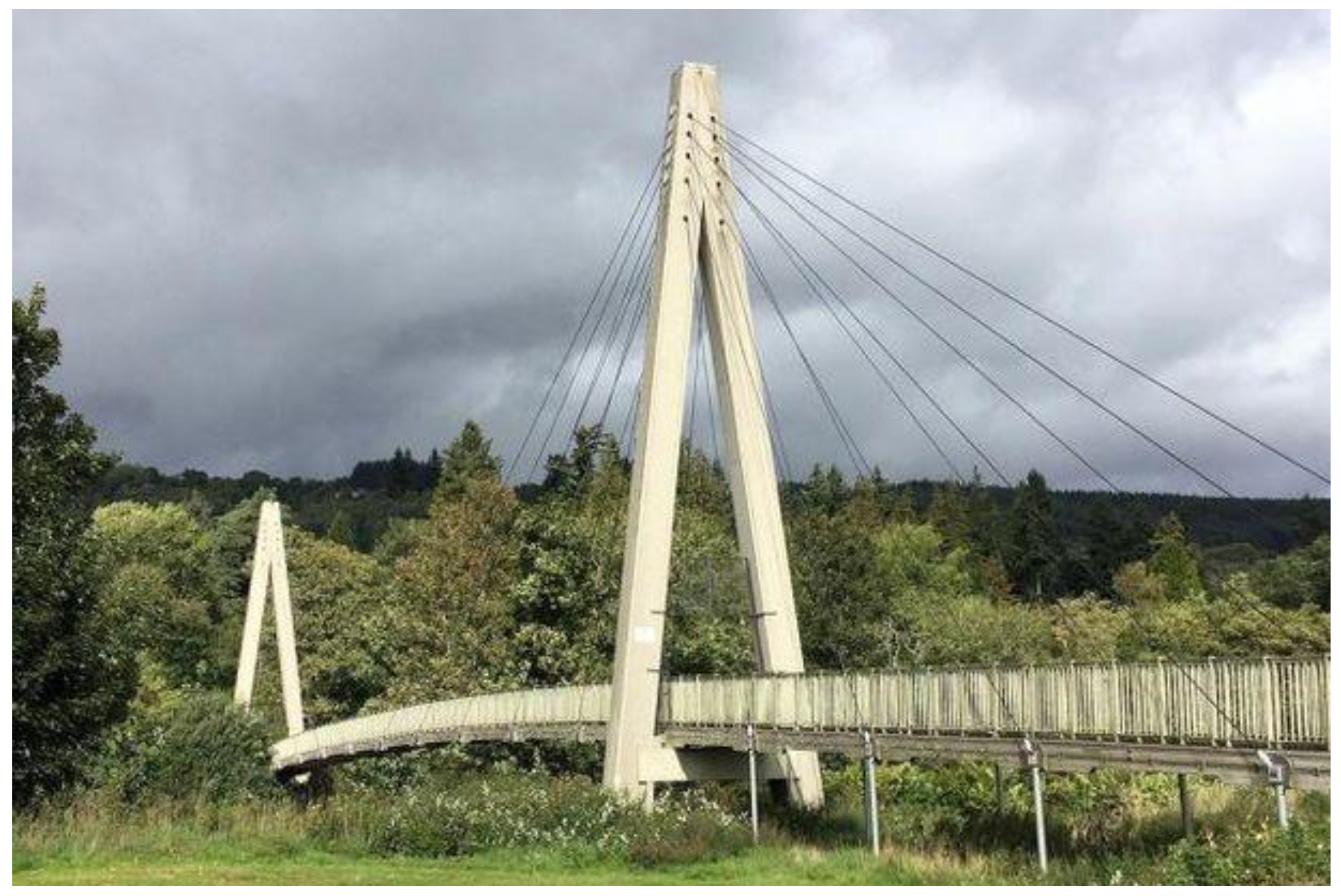
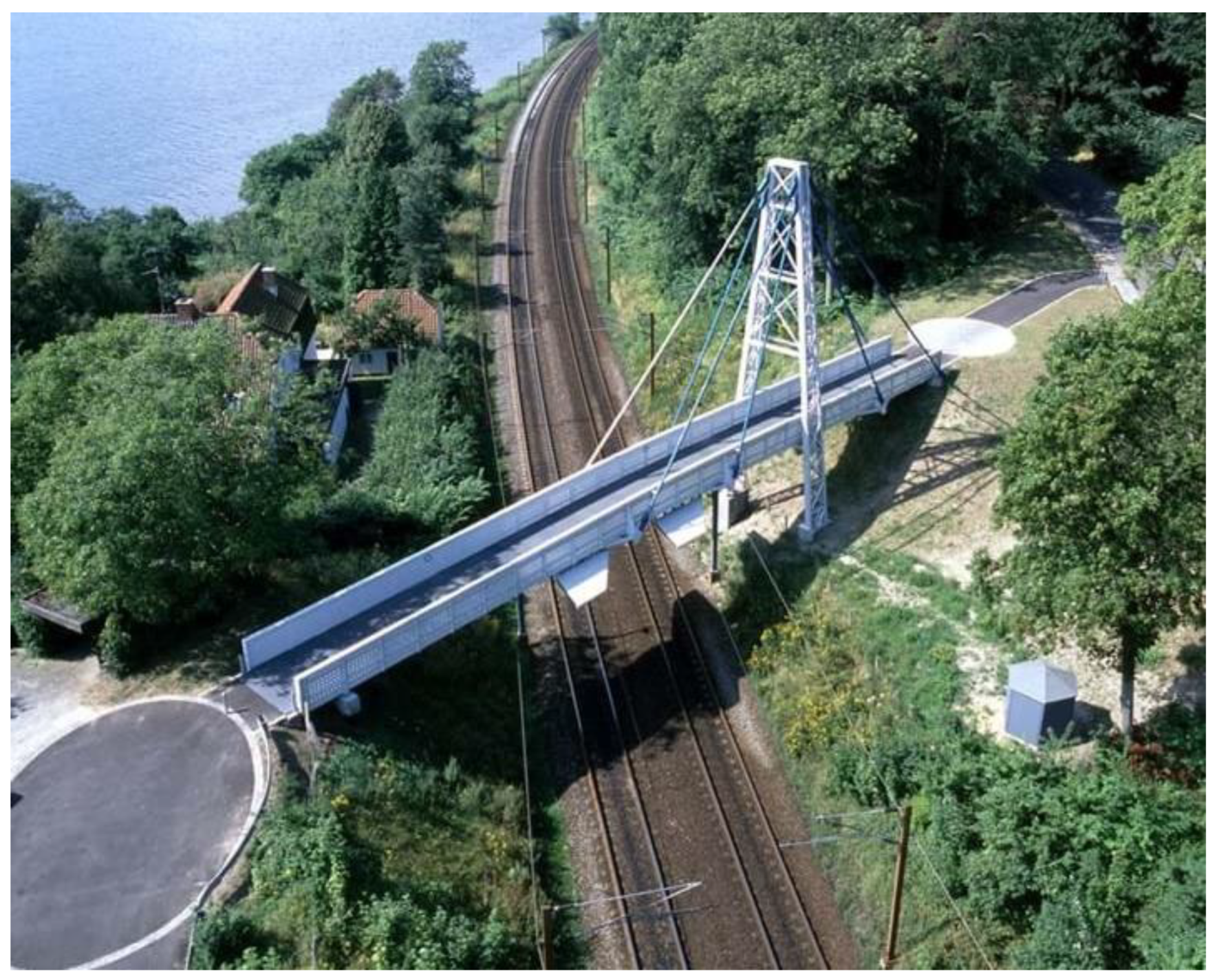
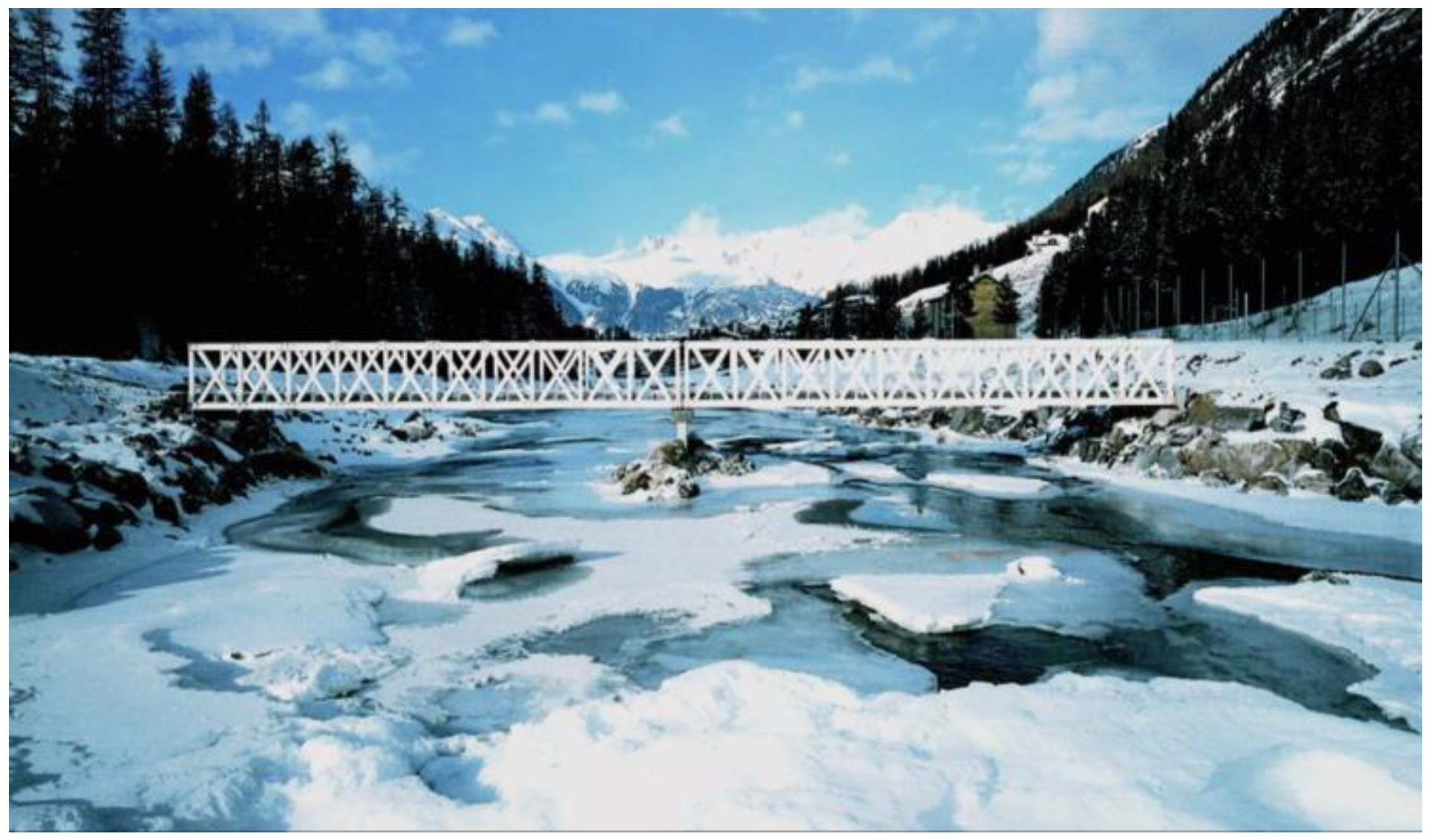
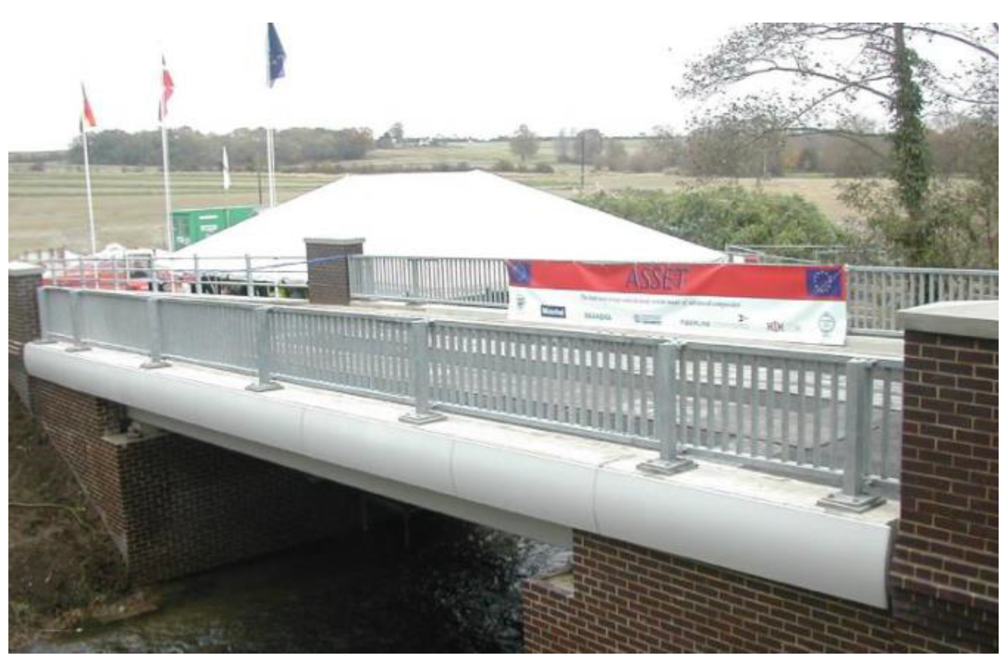
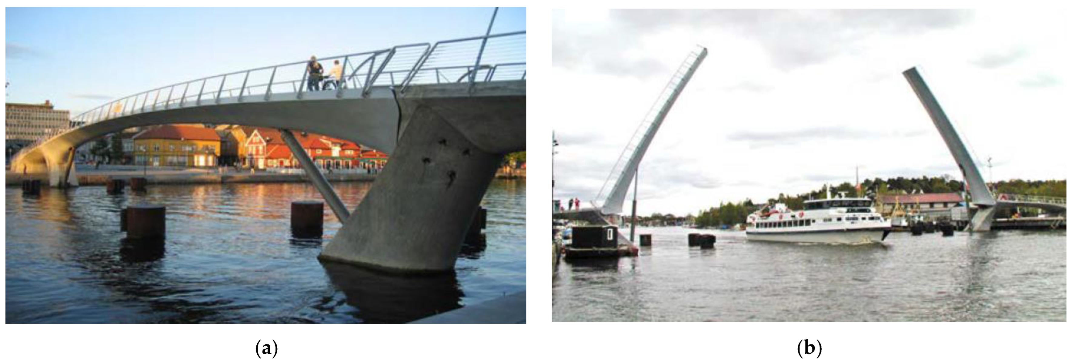
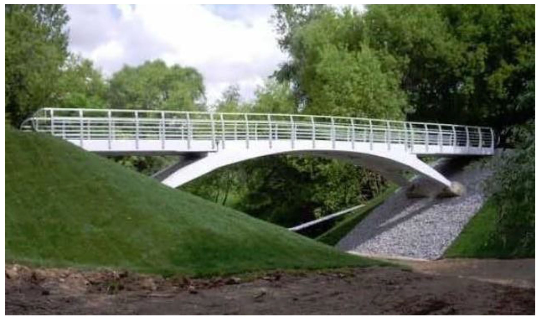
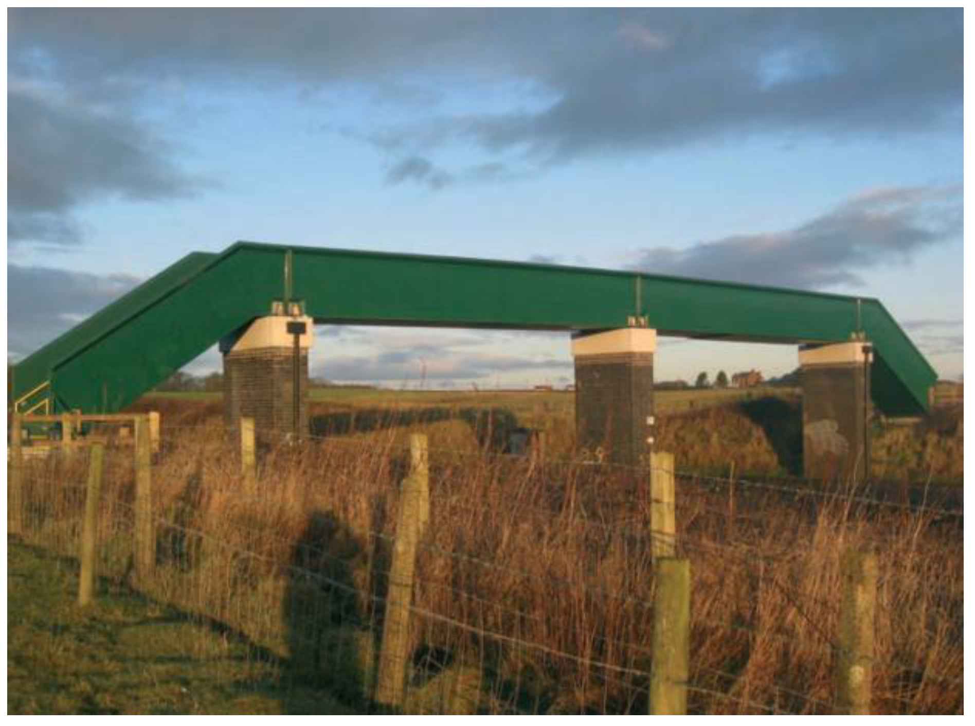
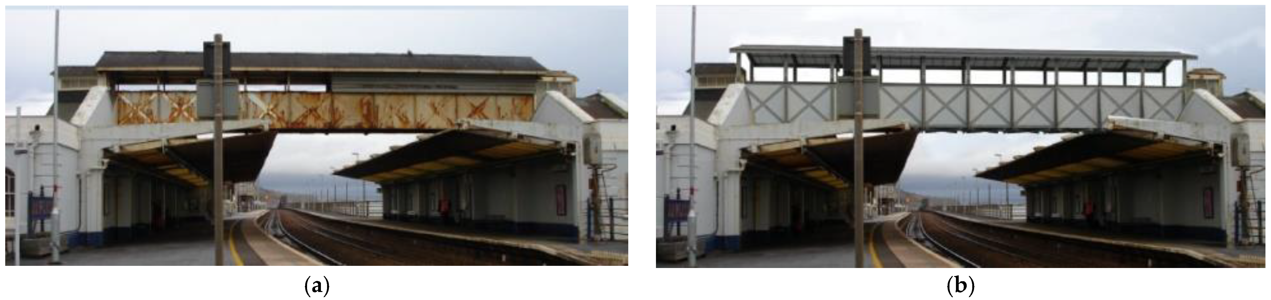
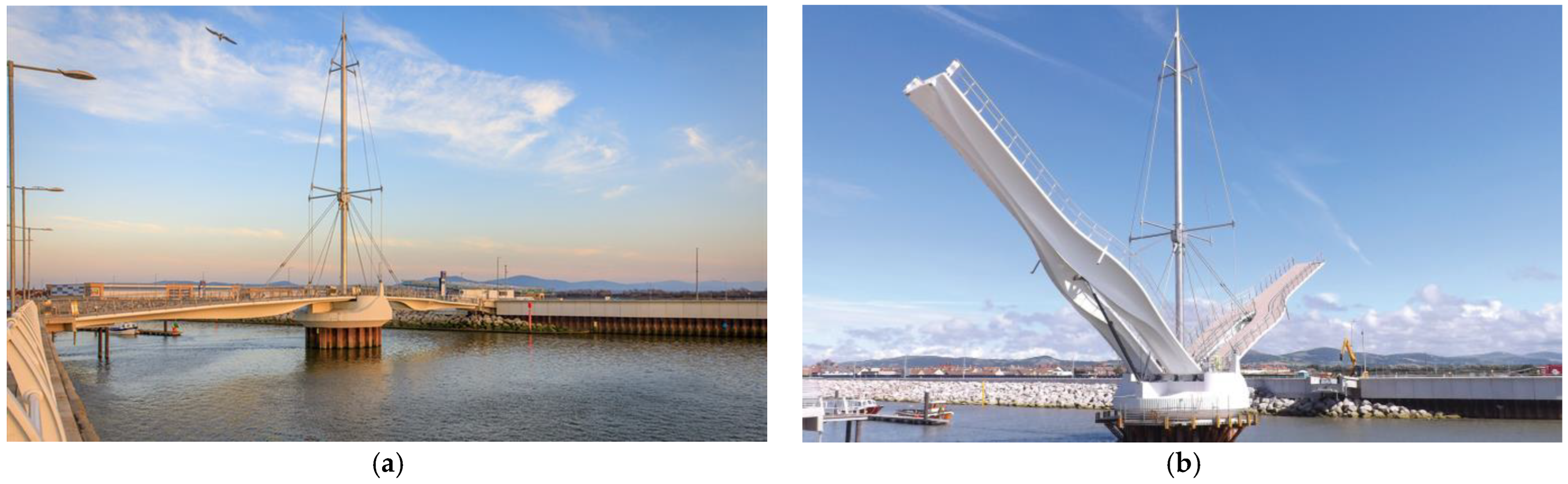
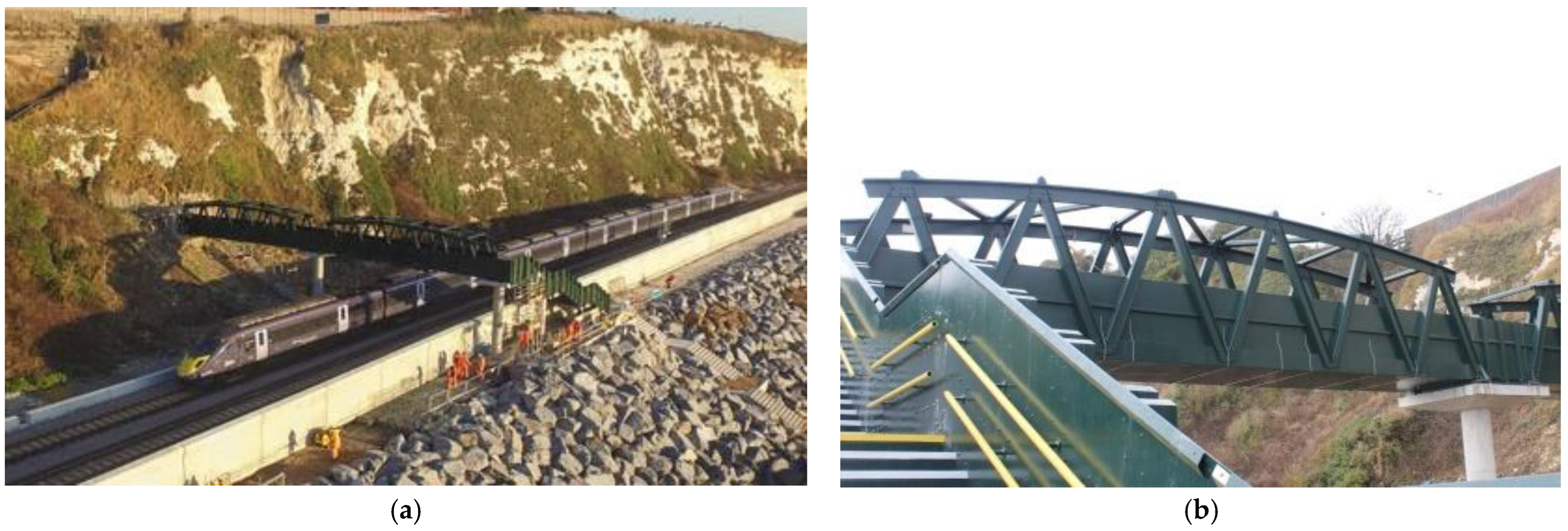
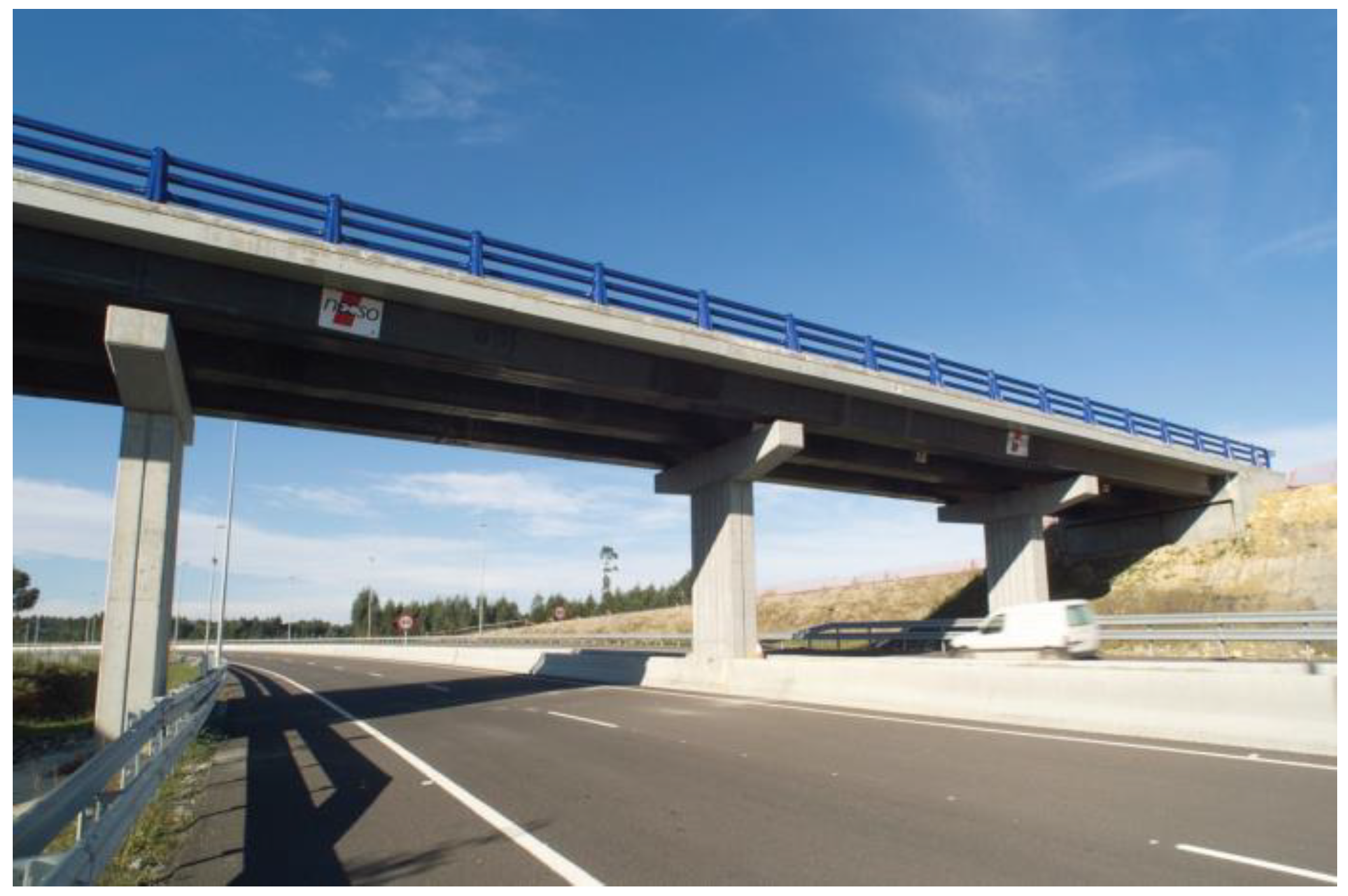
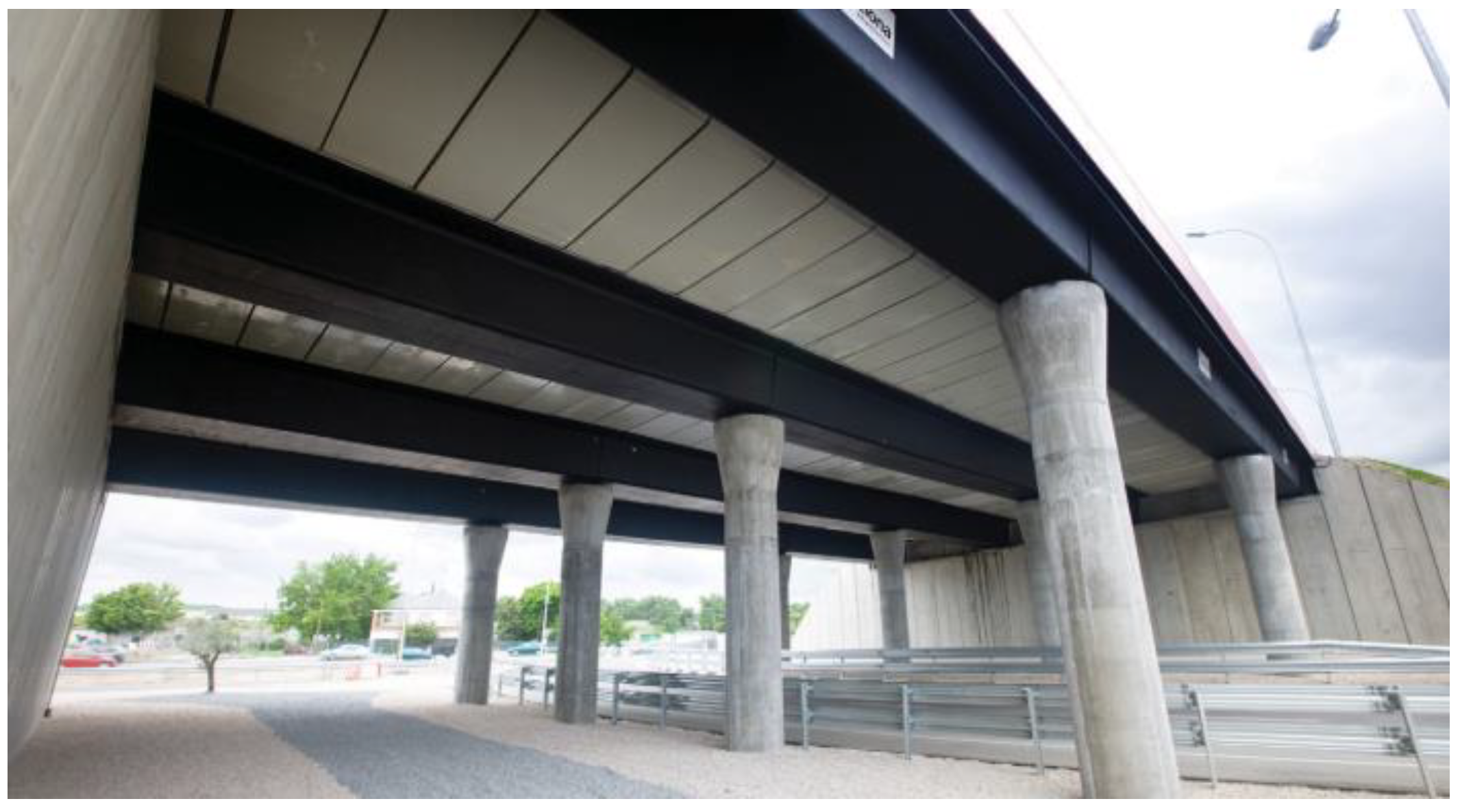
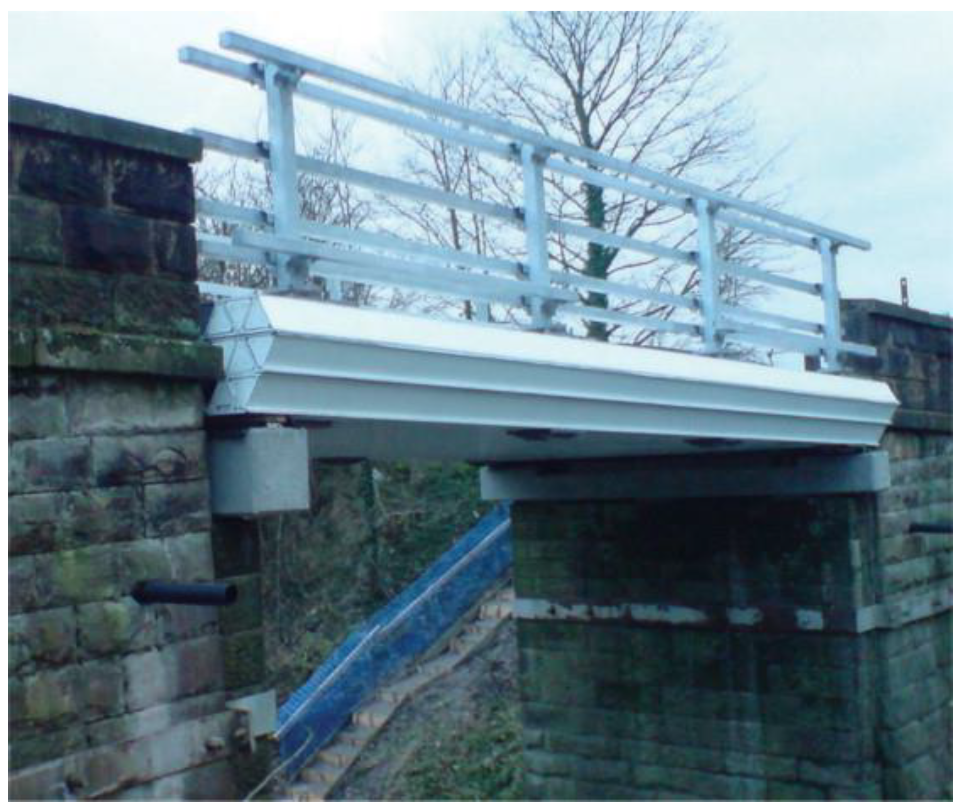
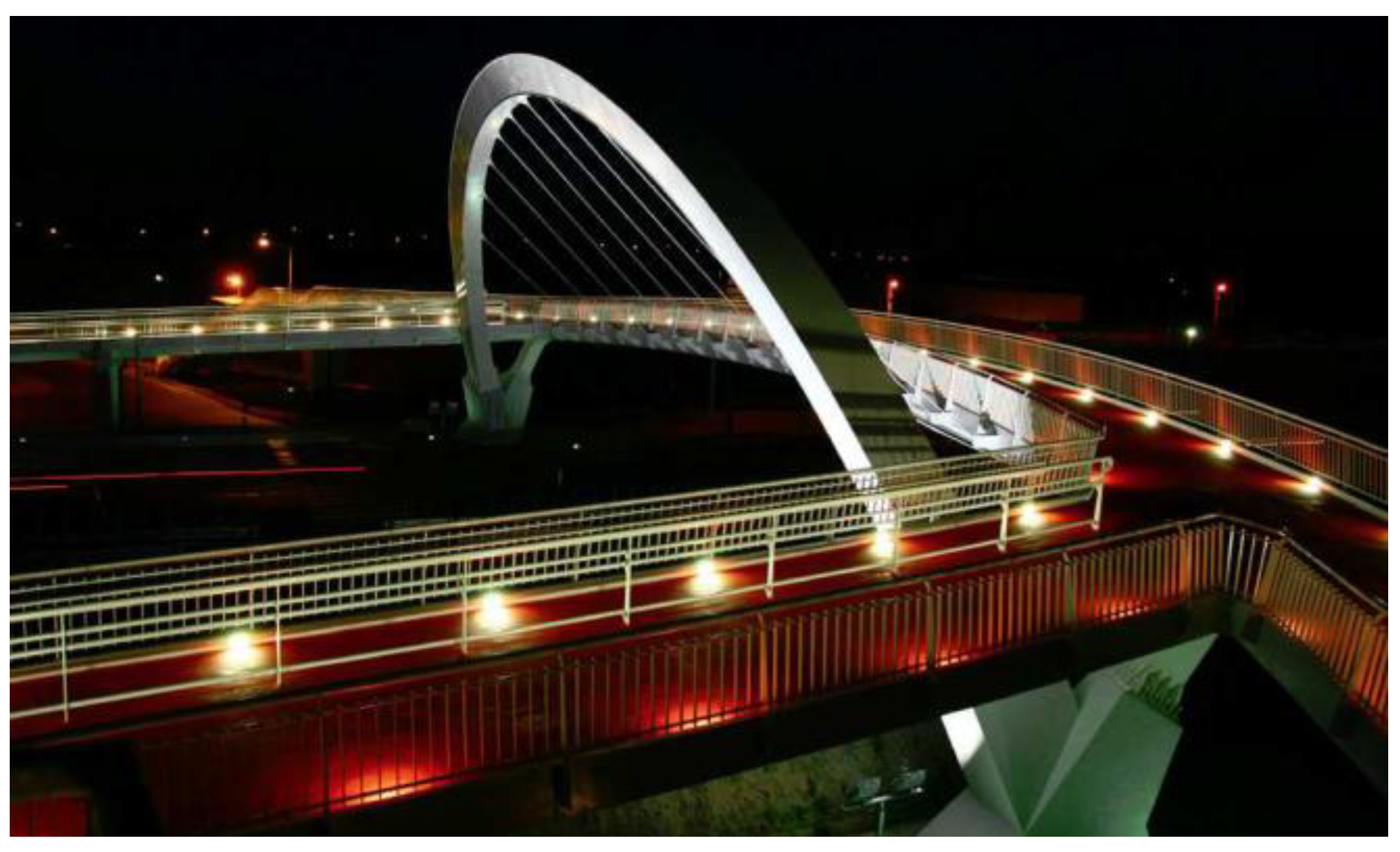
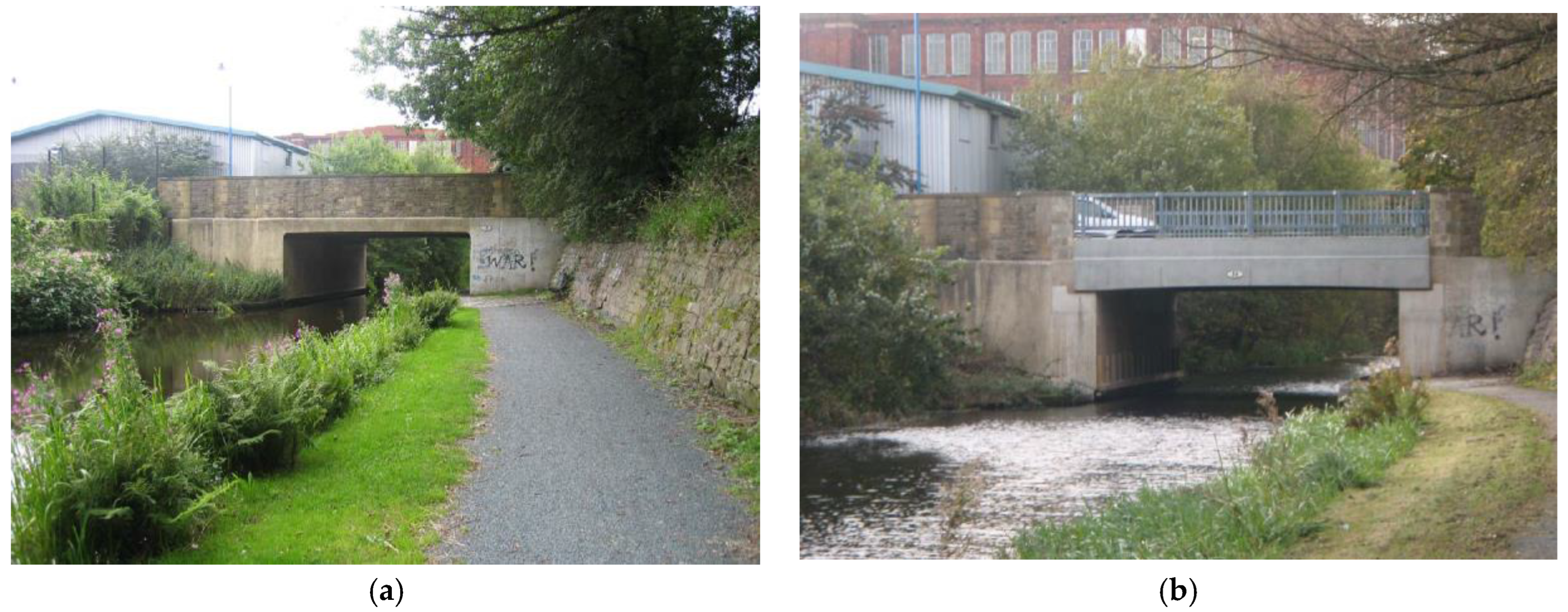
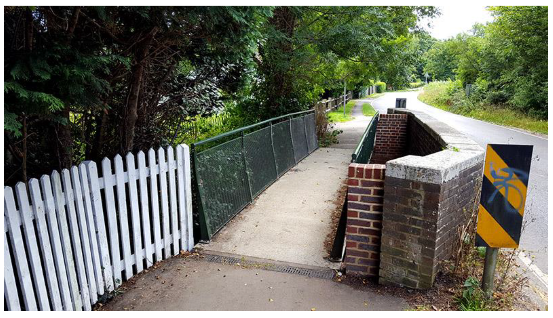
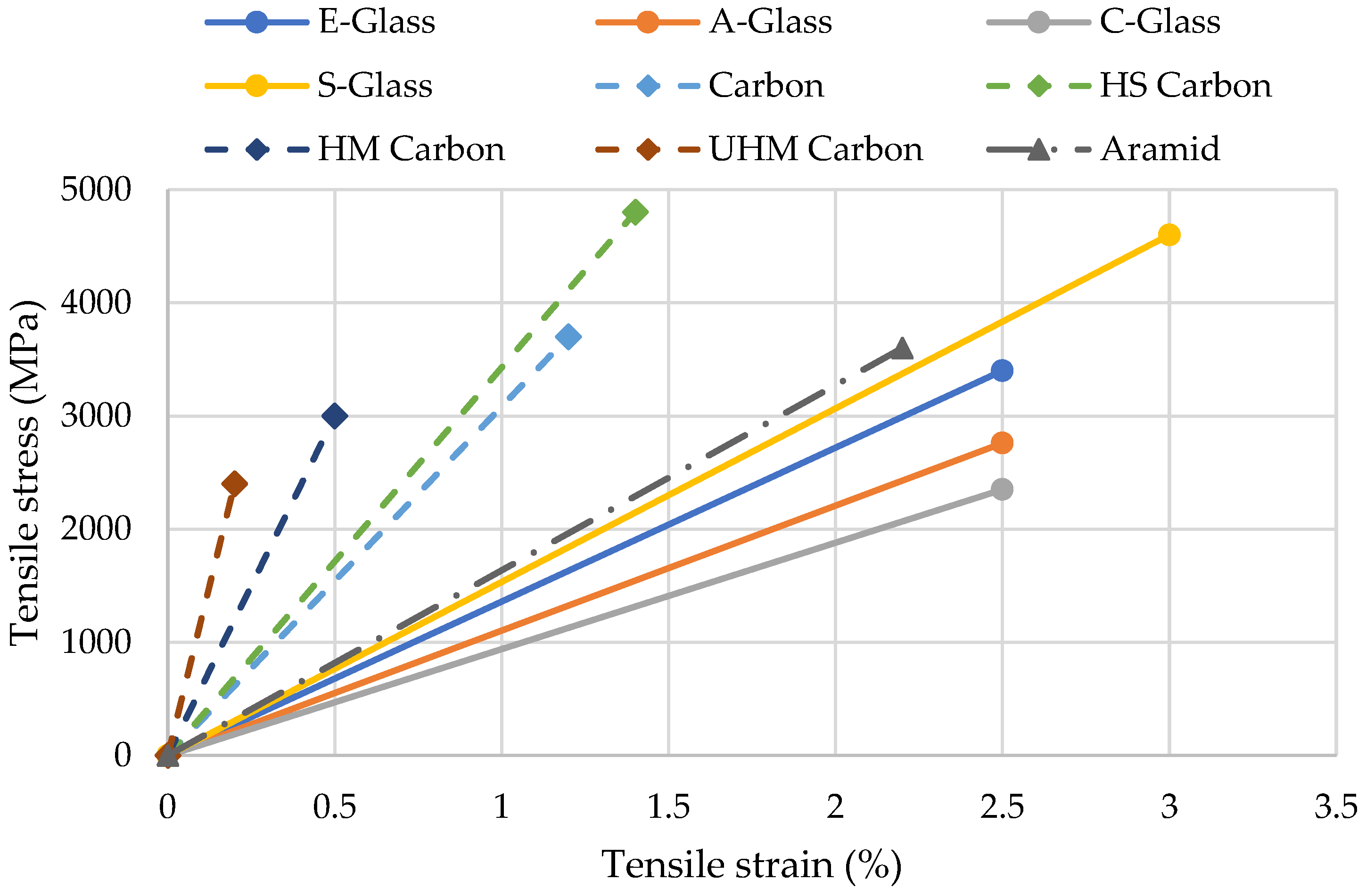
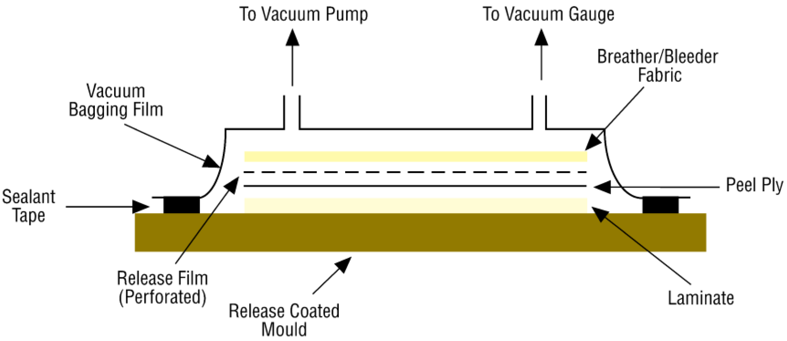
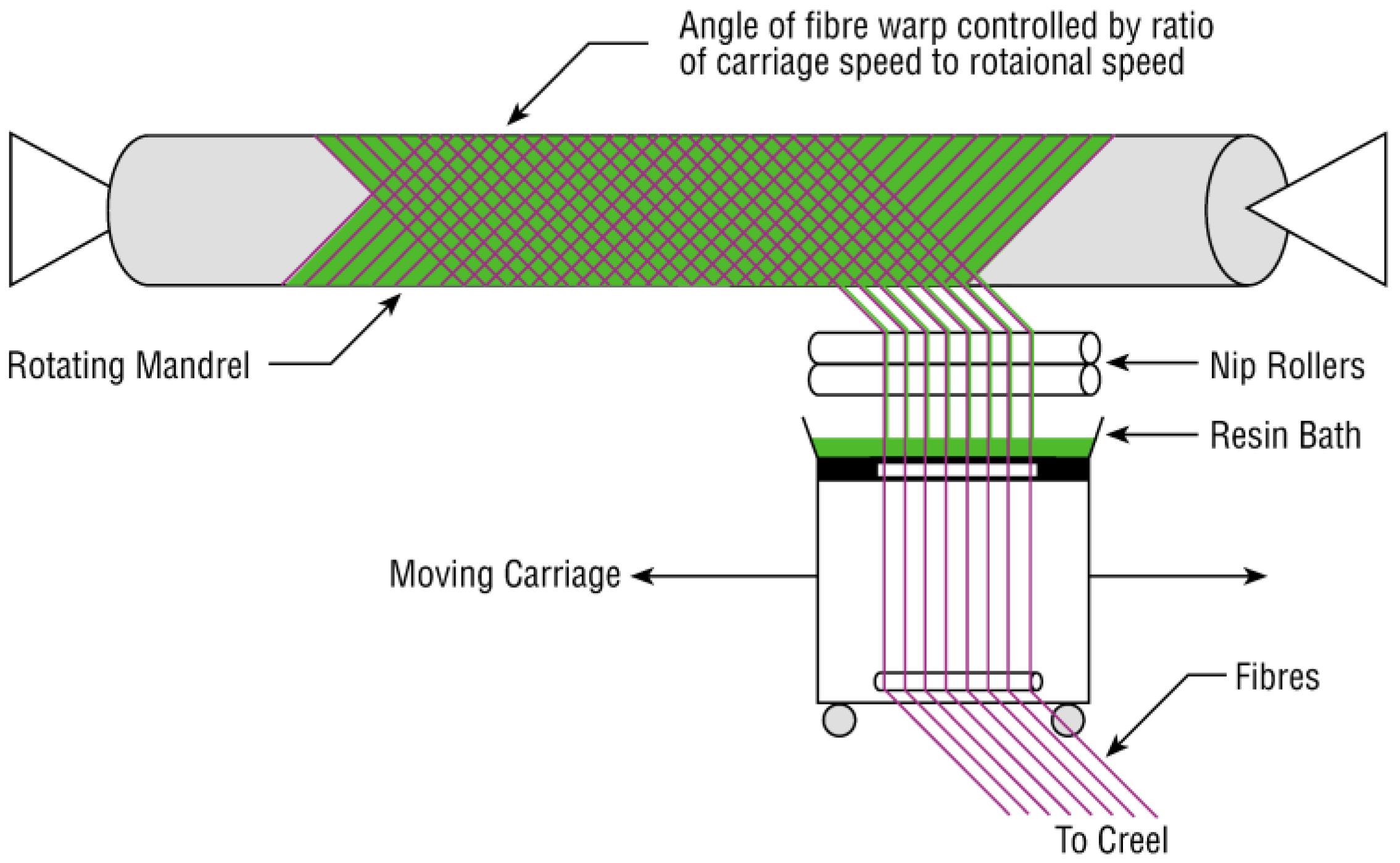
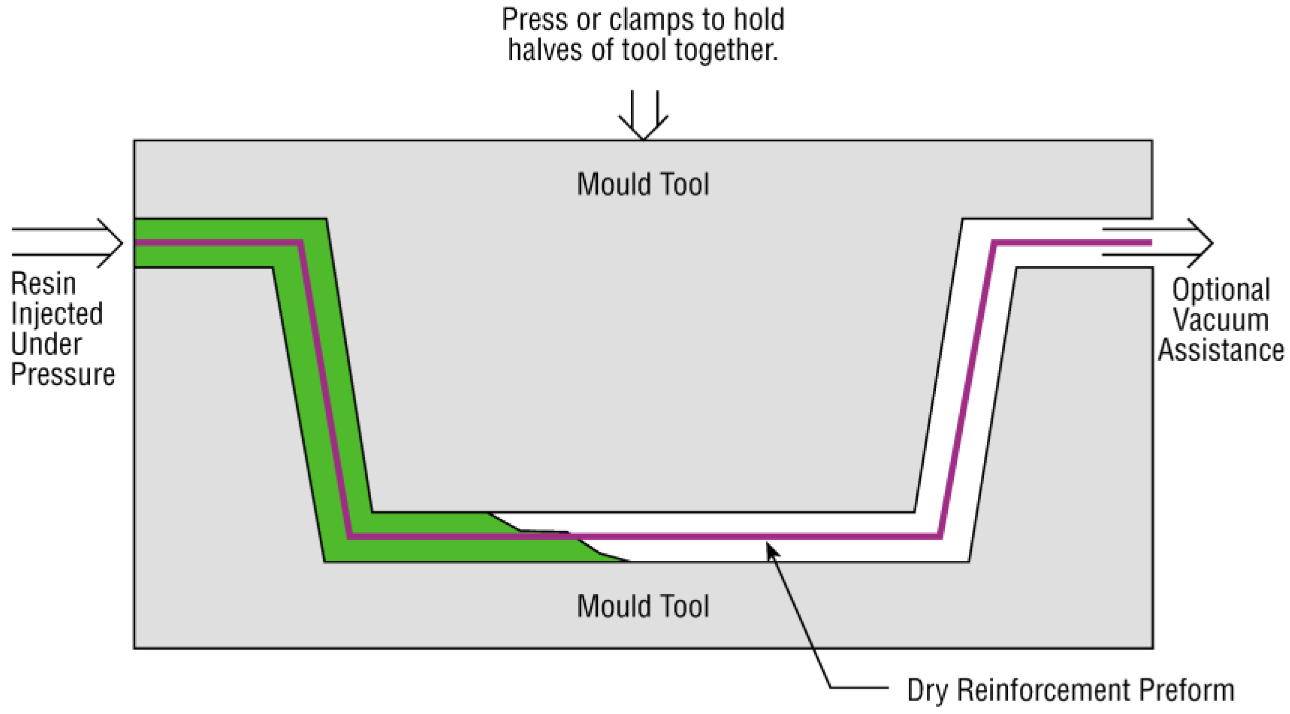
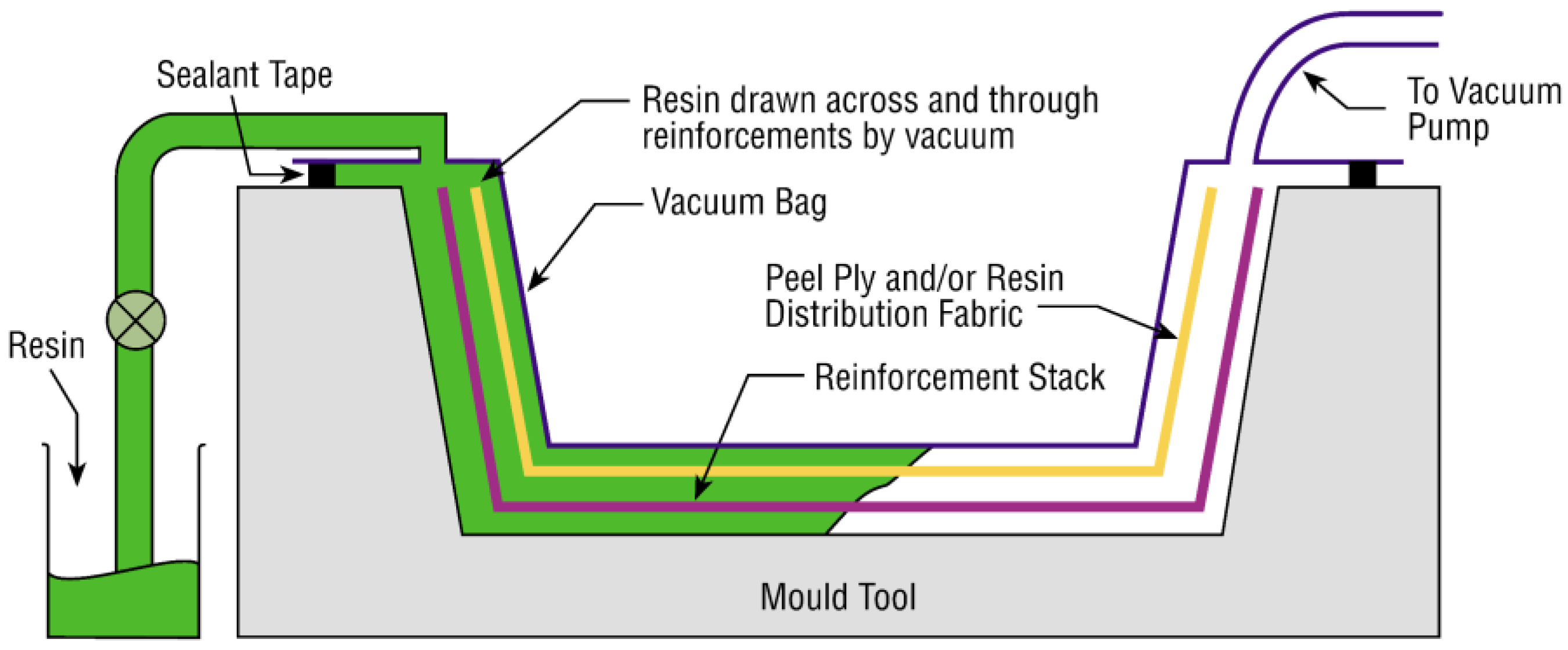
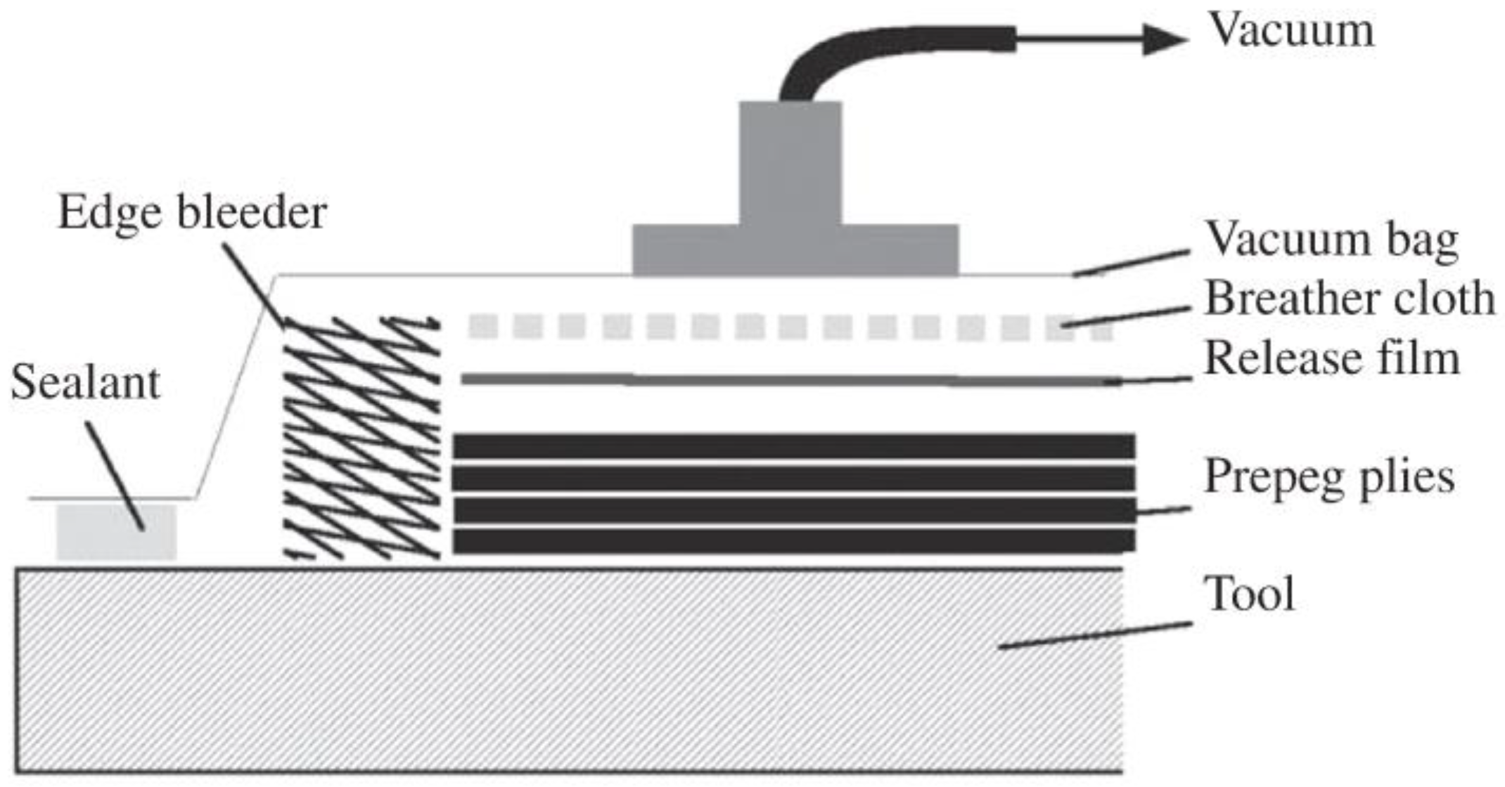
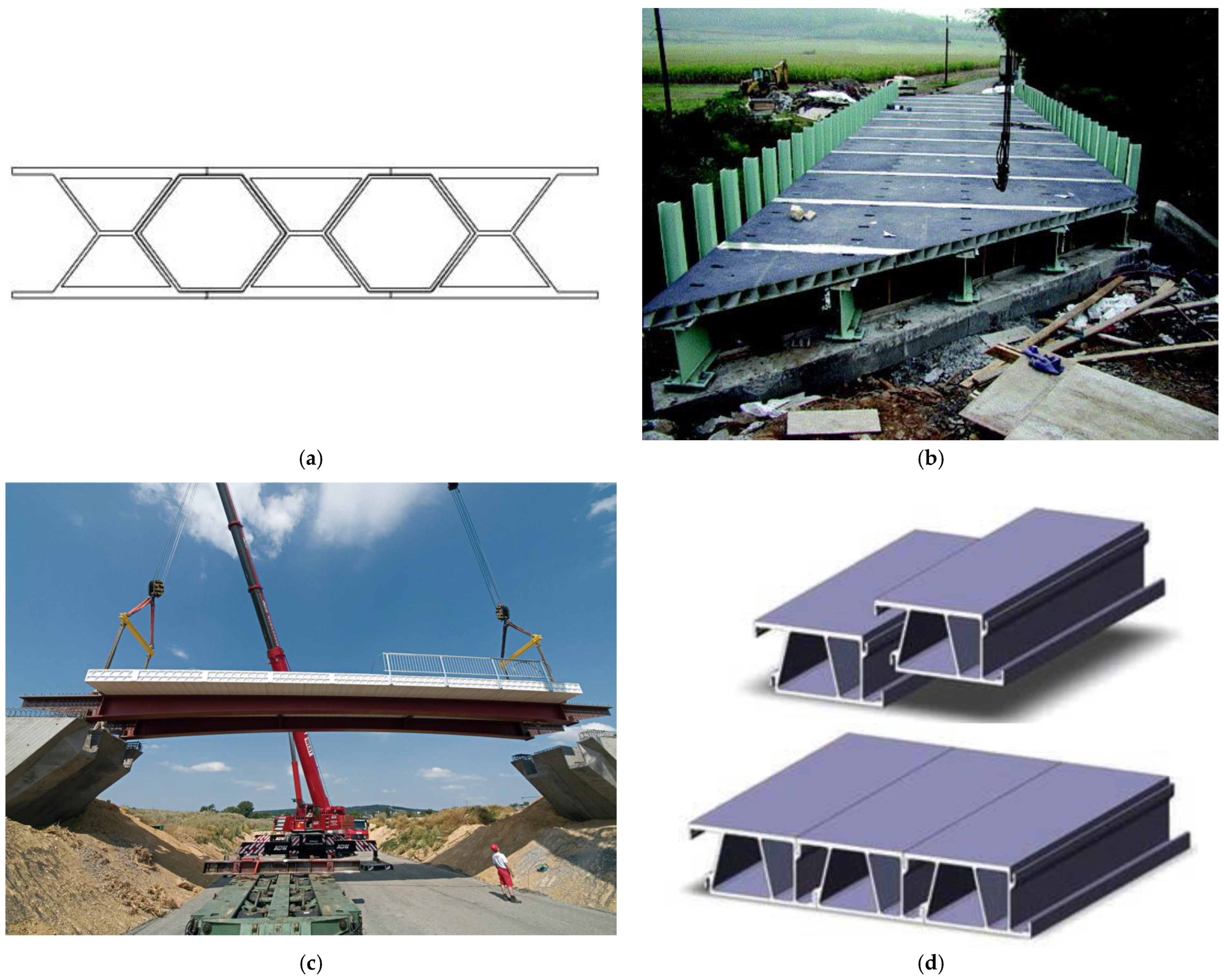
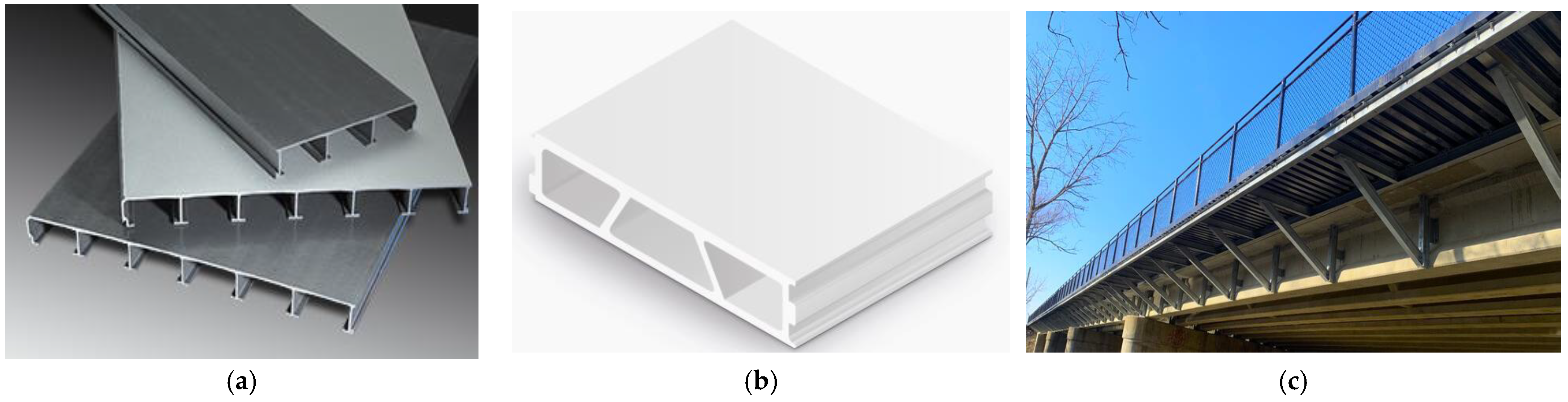
Figure 5.
Halgover Footbridge, Bodmin, UK, 2001 [49].
Figure 5.
Halgover Footbridge, Bodmin, UK, 2001 [49].

Figure 6.
Lleida Footbridge, Spain, 2001 [50].
Figure 6.
Lleida Footbridge, Spain, 2001 [50].

Figure 7.
West Mill Bridge, Oxfordshire, UK, 2002 [52].
Figure 7.
West Mill Bridge, Oxfordshire, UK, 2002 [52].

Figure 8.
Fredrikstad Bascule Footbridge Norway, built in 2003 [55]: (a) Bridge in a closed state; (b) Bridge in an open state for navigation.
Figure 8.
Fredrikstad Bascule Footbridge Norway, built in 2003 [55]: (a) Bridge in a closed state; (b) Bridge in an open state for navigation.

Figure 9.
St Austell Railway Bridge, Cornwall, UK, built in 2007 [56]: (a) Front view of the bridge; (b) Side view of the bridge.
Figure 9.
St Austell Railway Bridge, Cornwall, UK, built in 2007 [56]: (a) Front view of the bridge; (b) Side view of the bridge.

Figure 10.
ApATeCh arched footbridge, Moscow, Russia, built in 2008 [39].
Figure 10.
ApATeCh arched footbridge, Moscow, Russia, built in 2008 [39].

Figure 11.
Bradkirk Footbridge, Kirkham, Lancashire, UK, built in 2009, with permission from Taylor & Francis, License Number: 5538760110498 [59].
Figure 11.
Bradkirk Footbridge, Kirkham, Lancashire, UK, built in 2009, with permission from Taylor & Francis, License Number: 5538760110498 [59].

Figure 12.
Dawlish Railway Footbridge, Exeter, South Devon, UK [1]: (a) Old rusty steel bridge using riveted built section and cross bracing, 1937; (b) New FRP bridge using pultruded FRP profiles, moulded parapet and stairway, 2012.
Figure 12.
Dawlish Railway Footbridge, Exeter, South Devon, UK [1]: (a) Old rusty steel bridge using riveted built section and cross bracing, 1937; (b) New FRP bridge using pultruded FRP profiles, moulded parapet and stairway, 2012.

Figure 13.
Pont y Ddraig or the Dragon’s Bridge, Rhyl Harbour, North Wales, built in 2013 [62]: (a) Bridge in a lowered position; (b) Bridge in a raised position.
Figure 13.
Pont y Ddraig or the Dragon’s Bridge, Rhyl Harbour, North Wales, built in 2013 [62]: (a) Bridge in a lowered position; (b) Bridge in a raised position.

Figure 14.
Eindhoven bio-composite footbridge over the river Dommel, Eindhoven, The Netherlands, built in 2016 [63].
Figure 14.
Eindhoven bio-composite footbridge over the river Dommel, Eindhoven, The Netherlands, built in 2016 [63].

Figure 15.
Dover Sea Wall Footbridge, Dover, Kent, UK, built in 2017 [64]: (a) Complete footbridge over a railway line; (b) Bridge span directly on top of rail tracks.
Figure 15.
Dover Sea Wall Footbridge, Dover, Kent, UK, built in 2017 [64]: (a) Complete footbridge over a railway line; (b) Bridge span directly on top of rail tracks.

Figure 16.
Asturias composite bridge CFRP girders and concrete deck, Spain, built in 2004 [66].
Figure 16.
Asturias composite bridge CFRP girders and concrete deck, Spain, built in 2004 [66].

Figure 17.
M111 road bridges, Madrid, Spain, consisting of moulded FRP primary beams and concrete deck, were built in 2007 [65,68].

Figure 18.
Standen Hey Overbridge, Clitheroe, Lancashire, UK, built in 2007 [70].
Figure 18.
Standen Hey Overbridge, Clitheroe, Lancashire, UK, built in 2007 [70].

Figure 19.
Gądki Footbridge, Poland, built in 2008 [71].
Figure 19.
Gądki Footbridge, Poland, built in 2008 [71].

Figure 20.
Moss Canal road bridge, Rochdale, UK, built in 2011 [72]: (a) Original bridge with in situ concrete portal frame; (b) New FRP bridge using double web pultruded FRP beams and FRP deck with multiaxial E-glass fibres.
Figure 20.
Moss Canal road bridge, Rochdale, UK, built in 2011 [72]: (a) Original bridge with in situ concrete portal frame; (b) New FRP bridge using double web pultruded FRP beams and FRP deck with multiaxial E-glass fibres.

Figure 21.
Mapledurham Footbridge, Mapledurham, Oxfordshire, UK, built in 2015 [8]: (a) FRP bridge deck delivered to site by floating on a barge along River Thames; (b) Mapledurham FRP bridge installed with no physical joints.
Figure 21.
Mapledurham Footbridge, Mapledurham, Oxfordshire, UK, built in 2015 [8]: (a) FRP bridge deck delivered to site by floating on a barge along River Thames; (b) Mapledurham FRP bridge installed with no physical joints.

Figure 22.
Sedlescombe Footbridge, East Sussex, UK, built in 2015 [8].
Figure 22.
Sedlescombe Footbridge, East Sussex, UK, built in 2015 [8].

Figure 23.
Uniaxial tension stress–strain curves for unidirectional glass, carbon and aramid fibres.
Figure 23.
Uniaxial tension stress–strain curves for unidirectional glass, carbon and aramid fibres.

Figure 24.
Schematic representation of spray lay-up method [90].
Figure 24.
Schematic representation of spray lay-up method [90].

Figure 25.
Schematic illustration of wet or hand lay-up method [8].
Figure 25.
Schematic illustration of wet or hand lay-up method [8].

Figure 26.
Schematic illustration of vacuum bagging method.

Figure 27.
Schematic illustration of filament winding method.

Figure 28.
Schematic illustration of the pultrusion method.

Figure 29.
Schematic illustration of Resin Transfer Moulding (RTM) method.

Figure 30.
Schematic diagram of Vacuum Assisted Resin Transfer Moulding (VARTM) method.

Figure 31.
Schematic diagram of prepreg autoclave method [90].
Figure 31.
Schematic diagram of prepreg autoclave method [90].

Figure 32.
FiberSPAN FRP Pedestrian Bridge Decks by Creative Composites [96]: (a) Moulded FiberSPAN deck panels; (b) Reinforcement and core details for FiberSPAN sandwich panels; (c) Installation of FiberSPAN deck on a pedestrian bridge.
Figure 32.
FiberSPAN FRP Pedestrian Bridge Decks by Creative Composites [96]: (a) Moulded FiberSPAN deck panels; (b) Reinforcement and core details for FiberSPAN sandwich panels; (c) Installation of FiberSPAN deck on a pedestrian bridge.

Figure 33.
FRP bridge decks fabricated using adhesively bonded pultruded shapes: (a) Superdeck by Creative Composites Group—USA [35]; (b) DuraSpan by Martin Marietta Composites installed at Dunnings Creek bridge, USA [99]; (c) FRP composite ASSET double deck by Fiberline bonded to steel beams at Friedberg Bridge, Germany [9]; (d) Delta deck—Korea [24].

Figure 34.
Lightweight FRP plank/deck system for walkways: (a) Strongwell plank 80 × 333 mm [101]; (b) Fiberline Ultra Duty Plank 80 × 333 mm [46]; (c) A cantilever sidewalk using FRP planks at Cass Avenue Bridge, Clinton, Southeast Michigan, USA, built in 2019, using Creative Composites’ deck system.

Figure 35.
Pultruded FRP highway bridge girders [101]: (a) Strongwell EXTERN DWB; (b) Route 601 highway bridge in Sugar Grove, Virginia, USA using EXTERN DWB 900 × 450 mm, built in 2001; (c) Tom’s Creek Bridge, Blacksburg, Virginia, USA, built in 1997 and used EXTERN DWB 200 × 150 mm.
Figure 35.
Pultruded FRP highway bridge girders [101]: (a) Strongwell EXTERN DWB; (b) Route 601 highway bridge in Sugar Grove, Virginia, USA using EXTERN DWB 900 × 450 mm, built in 2001; (c) Tom’s Creek Bridge, Blacksburg, Virginia, USA, built in 1997 and used EXTERN DWB 200 × 150 mm.

Figure 36.
FRP light truss bridges [3]: (a) FRP truss ready to install; (b) Full FRP truss bridge.
Figure 36.
FRP light truss bridges [3]: (a) FRP truss ready to install; (b) Full FRP truss bridge.

Figure 37.
Types of FRP cables [30,31]: (a) FRP parallel wire cable; (b) FRP twisted wire cable; (c) FRP plate cable; (d) FRP sheet cable.

Figure 38.
Applications of FRP cables in cable-supported bridges [31]: (a) Stork Bridge in Winterthur, Switzerland, 1996; (b) Laroin CFRP Footbridge, France, 2002; (c) Herning Footbridge in Denmark, 1999.
Figure 38.
Applications of FRP cables in cable-supported bridges [31]: (a) Stork Bridge in Winterthur, Switzerland, 1996; (b) Laroin CFRP Footbridge, France, 2002; (c) Herning Footbridge in Denmark, 1999.

| Material | Grade | Density (g/cm3) | Tensile Modulus (GPa) | Tensile Strength (MPa) | Max Elongation (%) | Fibre Architecture | Glass Transition Temperature (°C) | |
|---|---|---|---|---|---|---|---|---|
| Fibre | Glass | E | 2.57 | 73 | 3400 | 2.5 | Isotropic | -- |
| A | 2.46 | 73 | 2760 | 2.5 | ||||
| C | 2.46 | 74 | 2350 | 2.5 | ||||
| S | 2.47 | 88 | 4600 | 3.0 | ||||
| Carbon | Standard | 1.70 | 250 | 3700 | 1.2 | Anisotropic | -- | |
| High strength | 1.80 | 250 | 4800 | 1.4 | ||||
| High modulus | 1.90 | 500 | 3000 | 0.5 | ||||
| Ultrahigh modulus | 2.10 | 800 | 2400 | 0.2 | ||||
| Aramid | -- | 1.40 | 70–190 | 2800–4100 | 2.0–2.4 | Anisotropic | ||
| Polymer Resin | Polyester | -- | 1.20 | 4.0 | 65 | 2.5 | -- | 70–120 |
| Epoxy | -- | 1.20 | 3.0 | 90 | 8.0 | -- | 100–270 | |
| Vinylester | -- | 1.12 | 3.5 | 82 | 6.0 | -- | 102–150 | |
| Phenolic | -- | 1.24 | 2.5 | 40 | 1.8 | -- | 260 | |
| Polyurethane | -- | varies | 2.9 | 71 | 5.9 | -- | 135–140 [79] | |
Disclaimer/Publisher’s Note: The statements, opinions and data contained in all publications are solely those of the individual author(s) and contributor(s) and not of MDPI and/or the editor(s). MDPI and/or the editor(s) disclaim responsibility for any injury to people or property resulting from any ideas, methods, instructions or products referred to in the content. |
© 2023 by the author. Licensee MDPI, Basel, Switzerland. This article is an open access article distributed under the terms and conditions of the Creative Commons Attribution (CC BY) license (https://creativecommons.org/licenses/by/4.0/).
Share and Cite
MDPI and ACS Style
Qureshi, J. A Review of Fibre Reinforced Polymer Bridges. Fibers 2023, 11, 40. https://doi.org/10.3390/fib11050040
AMA Style
Qureshi J. A Review of Fibre Reinforced Polymer Bridges. Fibers. 2023; 11(5):40. https://doi.org/10.3390/fib11050040
Chicago/Turabian StyleQureshi, Jawed. 2023. "A Review of Fibre Reinforced Polymer Bridges" Fibers 11, no. 5: 40. https://doi.org/10.3390/fib11050040
Note that from the first issue of 2016, this journal uses article numbers instead of page numbers. See further details here.