

Effective Strengthening of RC Beams Using Bamboo-Fibre-Reinforced Polymer: A Finite-Element Analysis
by
 , , and
Jia Ning Siew
1,
Qi Yan Tan
1,
Kar Sing Lim
1,
Jolius Gimbun
2,3 ,
,
Kong Fah Tee
4,5,* and
Siew Choo Chin
1,3,* 1
Faculty of Civil Engineering Technology, Universiti Malaysia Pahang, Gambang 26300, Malaysia
2
Faculty of Chemical and Process Engineering Technology, Universiti Malaysia Pahang, Gambang 26300, Malaysia
3
Centre for Research in Advanced Fluid and Processes (Fluid Centre), Universiti Malaysia Pahang, Gambang 26300, Malaysia
4
Department of Civil and Environmental Engineering, King Fahd University of Petroleum and Minerals, Dhahran 31261, Saudi Arabia
5
Interdisciplinary Research Center for Construction and Building Materials, King Fahd University of Petroleum and Minerals (KFUPM), Dhahran 31261, Saudi Arabia
*
Authors to whom correspondence should be addressed.
Fibers 2023, 11(5), 36; https://doi.org/10.3390/fib11050036
Submission received: 14 November 2022
/
Revised: 14 April 2023
/
Accepted: 19 April 2023
/
Published: 22 April 2023
(This article belongs to the Special Issue Sustainable High Performance Fiber-Reinforced Cementitious Composites (HPFRCCs) and Fiber-Reinforced Polymers (FRPs))
Abstract
:This paper presents a finite-element model of the structural behaviour of reinforced concrete (RC) beams with and without openings externally strengthened with bamboo-fibre-reinforced composite (BFRC) plates. The simulation was performed using ABAQUS Unified FEA 2021HF8 software. The stress–strain relationship of the RC was modelled using a model code for concrete structures, whereas the concrete-damaged plasticity model was used to simulate concrete damage. The predicted crack pattern of the beams was comparable to that from experimental observations. The ultimate load-bearing capacity of RC beams in flexure was predicted with an error of up to 1.50%, while the ultimate load-bearing capacity of RC beams with openings in shear was predicted with an error ranging from 1.89 to 13.43%. The most successful arrangement for strengthening a beam with openings in the shear zone was to place BFRC plates perpendicular to the crack on both sides of the beam’s surface, which increased the beam’s original load-bearing capacity by 110.06% compared to that of the control beam (CB). The most effective method for strengthening RC beams in flexure is to attach a BFRC plate to the entire bottom soffit of the RC beam. This maximises the ultimate load-bearing capacity at the expense of the beam’s ductility.
1. Introduction
Web openings in reinforced concrete beams are commonly provided for the passage of utility pipes and ducts [1] in order to accommodate essential mechanical and electrical building services [2,3]. Openings are occasionally necessary on sites due to abrupt changes in the building’s purpose [4]. However, such web openings may dramatically reduce the beam’s capacity and affect its serviceability [1]. The provision of openings also changes the simple beam behaviour into complex [3].
There is a need to strengthen and retrofit deteriorated or damaged structures [5,6]. The deterioration of structures can be due to environmental influences, inadequate design and construction, structural upgrades, steel corrosion due to exposure to aggressive environments, accident events such as earthquakes, poor concrete quality, and excessive deflection. Therefore, strengthening structures is vital to address the aforementioned problems.
The external strengthening of beams is preferred over steel reinforcement to avoid hacking and drilling into existing beams, which could result in further damage [4]. In the early 1990s, fibre-reinforced polymer (FRP) composites were widely used as externally bonded reinforcements for strengthening existing RC structures [7] and retrofitting works [8]. FRP materials have outstanding properties such as corrosion resistance, light weight, fatigue resistance, and high tensile strength [9,10,11]. Due to their remarkable properties, FRPs are also considered an alternative to conventional steel [10].
FRPs are primarily developed from synthetic fibres such as carbon, aramid, and glass. However, the use of synthetic fibres is not environmentally friendly, it is nonbiodegradable and poorly recycled, and has high production costs [6,8,12]. The production of synthetic fibres requires a large amount of fossil fuels and is energy-intensive [13,14]. It is estimated that 300 GJ is required to produce 1 tonne of carbon fibres. Compared to hemp, this natural fibre only requires 5 GJ [13,15]. This energy consumption is equivalent to the amount of greenhouse gases emitted during fibre production. A tonne of carbon fibres produced around 29,500 kg CO2, and one tonne of glass fibres produced roughly 1700–2500 kg CO2. Natural fibres such as hemp, flax, jute, and kenaf produced approximately 410, 350, 550, and 420 kg CO2 per tonne of fibre, respectively [13,16]. The production of synthetic FRPs releases toxic byproducts that can be detrimental to human health depending on the level of exposure [7,13,17,18,19].
Due to the disadvantages of FRPs, researchers have turned to natural plant fibres as an alternative to synthetic types [20] because of their biorenewable properties and ecofriendly characteristics. Natural plant fibres include flax, hemp, jute, sisal, coir, kapok, and banana [21]. Natural fibres have numerous advantages over synthetic fibres, including low cost and density, comparable specific tensile properties, nonirritation to the skin, lower health risk, and recyclability and biodegradability [22,23]. Compared to other natural fibres such as sisal, kenaf, and jute, bamboo fibres possess good mechanical properties [23], such as lower density (608–780 kg/m3), higher tensile strength (140–800 MPa), and a lower modulus (11–46 GPa) [24,25,26].
Over the last few years, natural-plant-fibre-reinforced composites have gained increasing attention as a viable alternative to FRPs [27]. Natural-fibre-based composites have superior properties such as low cost, light weight, biodegradability, and high specific strength and stiffness [25]. In contrast to synthetic fibres, natural fibres can be incinerated at the end of their useful lives, with improved energy recovery and without adding to CO2 emissions, resulting in positive carbon credits and a lower global warming effect. Hence, the utilisation of natural-fibre-reinforced composite fibres is one of the key alternatives to solving environmental problems [28,29].
Many researchers consider bamboo processed into fibres, and then transform the fibre into reinforcing material in polymer matrices. Among other fibres, bamboo is selected as reinforcement due to its superior mechanical and thermal properties, rapid growth rate, local availability, low cost, environmentally friendly nature, and widespread global accessibility in tropical and subtropical regions [4,23,26,28,30]. On the basis of its excellent mechanical properties, bamboo fibre is considered a natural glass fibre [31,32]. Polymer matrices commonly used with natural fibre composites include epoxy, polyester, polypropylene (PP), and polyethylene (PE) [25]. Additionally, bamboo fibre composites produced with epoxy resin have many advantages, such as light weight, high strength, good fatigue resistance, good buffer performance, low cost, low energy consumption, and nontoxicity [31]. Epoxy resin is widely accepted in engineering fields due to its excellent mechanical properties, chemical resistance, and electrical insulation [23]. Bamboo-fibre-epoxy-based composites could replace glass fibre composites in the majority of applications [31,33].
Most earlier research experimented on structural strengthening, particularly with natural-fibre-reinforced polymers [4,6,34,35,36,37,38]. Most previous investigations utilised kenaf [35,36,38] and jute [36,37,39] fibres as composites for the external strengthening of solid RC beams. However, there are few studies on the utilisation of bamboo-fibre-reinforced composites as the external strengthening material of RC beams [4,34].
Nwanko and Ede [35] utilised a kenaf-fibre-reinforced polymer (KFRP) laminate to strengthen RC beams in flexure. The KFRP increased the ultimate load of the RC beam by 78%, and reduced beam deflection compared to the control beam.
Hafizah et al. [38] investigated the performance of kenaf fibre composites with various types of resins, including epoxy, polyester, and vinyl ester. Strengthening RC beams in flexure using kenaf fibre epoxy composite increases beam flexural strength and reduces deflection. Sen and Reddy [39] studied the flexural strengthening effect of RC beams using jute fibre (JFRP)-, carbon textile (CFRP)-, and glass textile (GFRP)-reinforced polymer composites. The strengthening configurations included U wrapping in a single layer along with the beam’s entire length with the full-wrapping and strip-wrapping techniques.
Alam and Al Riyami [36] studied the shear strengthening of RC beams using kenaf, jute, and jute-rope fibres in treated and untreated conditions. They found that natural fibre composite plates had higher ductility and higher failure loads compared to those of the control beams. A study using a jute-rope composite plate for the flexural strengthening of RC beams found 58% higher strength compared to that of the control beam [37].
Chin et al. [4] studied the behaviour of RC beams with openings strengthened using a bamboo-fibre-reinforced composite (BFRC) in the shear zone, and the strengthening of solid RC beams in flexure using BFRC. They studied various strengthening configurations using an epoxy-based BFRC. They reported that strengthening with a BFRC could regain the beam’s original capacity up to 98% of that of the control beam. Awoyera et al. [34] investigated the structural retrofitting of corroded reinforced concrete beams using a bamboo fibre laminate. A single laminate in the tensile region of the corroded beam increased the ultimate load capacity by up to 21% more than that of the corroded beam without retrofit.
The aforementioned literature showed that most previous experimental investigations primarily focused on the flexural strengthening of solid RC beams. Only a limited number of studies were performed on the shear strengthening of RC beams. Previous investigations mostly focused on solid RC beams rather than RC beams with openings. Natural-fibre-reinforced composites from previous work were produced mainly using kenaf and jute fibre composites. There are very few studies on the utilisation of bamboo-fibre-reinforced composite as the external strengthening material of RC beams.
There are only a few computational studies on BFRP in structural strengthening [40,41,42,43]. A numerical model of cantilever beams was produced using hemp, bamboo, and coir fibre composites to compare their performance with respect to their natural frequencies and damping values [40]. A nonlinear structural model for flexural bamboo beams was derived to analyse the nonlinear flexural behaviour of bamboo beams and predict the ultimate loads [41]. Hidayat et al. [42] performed the nonlinear finite element analysis of traditional flexural strengthening using betung bamboo (Dendrocalamus asper) on concrete beams. Sen and Reddy [43] conducted a nonlinear finite-element analysis to evaluate the performance of bamboo fibres in structural retrofitting. All previous investigations performing the finite-element analysis of bamboo composites mainly focused on the flexural strengthening of solid RC beams. However, no modelling studies have been conducted on the shear strengthening of RC beams with BFRC or RC beams with openings. Hence, this is the aim of the current work.
Computer simulations are vital to ensuring that a solution can be obtained faster with limited resources. Furthermore, various strengthening designs can be studied without the need to cast a beam and prepare a BFRP. There is limited research studying the effectiveness of BFRP in strengthening RC beams using finite-element analysis (FEA); hence, this is the aim of this work.
FEA was performed using ABAQUS Unified FEA version 2021HF8, and was validated with our experimental study [4]. Once validation had been successful, the model was used to predict the effect of various BFRP strengthening configurations on beam performance. The load–deflection behaviour, ultimate load-bearing capacity, and crack pattern of reinforced concrete beams with BFRP were investigated numerically. The ultimate aim of this work is to improve beam performance with opening with the external strengthening with BFRP beyond what was obtained from the experiment.
2. Methodology
2.1. Experimental Measurements
2.1.1. Preparation of RC Beams
Beam Groups A and B were used to assess the effects of shear and flexural strengthening [4]. The beams in Group A were controlled specimens (CB), unstrengthened beams with shear span openings (BUO), and beams with openings in the shear span strengthened with BFRP (BSO1). Group B’s beams were controlled specimens (CB), unstrengthened beams in the flexure zone (UB), and strengthened beams in the flexure zone (SB).
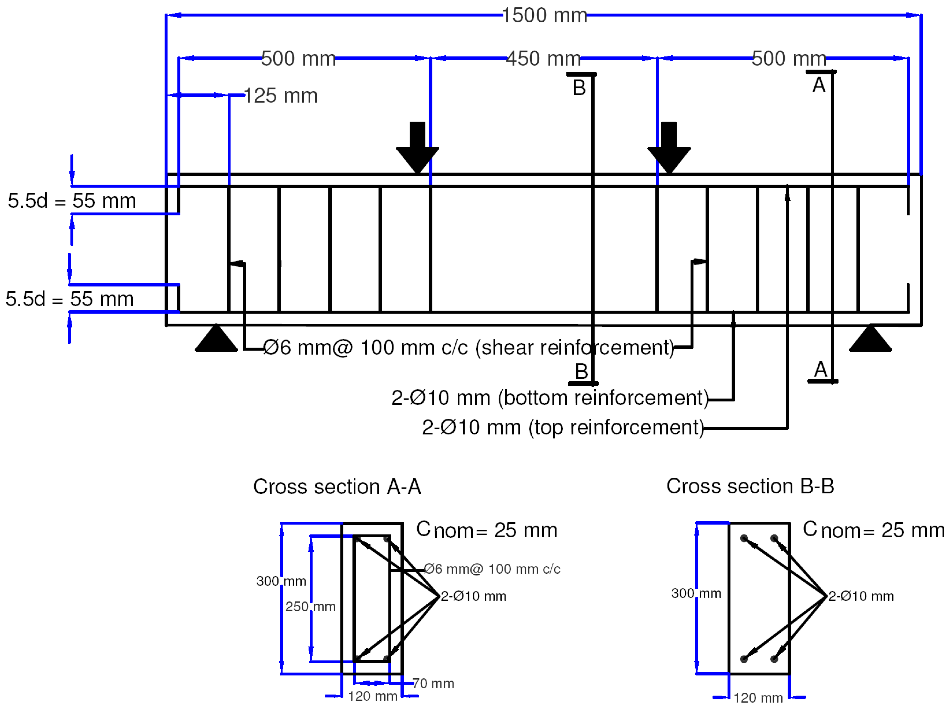
The two beam groups both had a width of 120 mm, a height of 300 mm, and a length beam of 1500 mm. All RC beams received longitudinal reinforcement in the form of two 10 mm diameter bars on the tension and compression sides, and shear reinforcement in the form of 6 mm diameter steel stirrups spaced 100 mm apart along the beam. The longitudinal reinforcement had a yield strength of 500 MPa and an elastic modulus of 200 GPa, while the stirrup had a yield strength of 250 MPa and an elastic modulus of 200 GPa. At 28 days, ready-mixed concrete was designed to have a compressive strength of 30 MPa. Two circular openings with a diameter of 120 mm were created at the shear spans of beams BUO and BSO1, and stirrups were not supplied around the openings in order to induce shear failure. UB and SB, on the other hand, did not include a stirrup in the flexure zone in order to encourage flexure failure.
2.1.2. BFRP Preparation
The BFRP plates used to strengthen the beams were hand-produced using a steel mould with dimensions of 120 × 8 × 450 mm. Each plate was composed of a base plate and a top plate. After the steel mould had been cleaned, a small layer of honey wax was added to facilitate the removal of the composite plate. The fibres were layered into the casting mould. Each layer was constructed with an equal fibre amount. The first layer of bamboo fibres was lain down systematically on the adhesive and gently pressed with a spatula to ensure that the fibres were completely saturated with resin. For interfacial bonding, the second layer of resin was poured on top of the first layer of bamboo fibres. Following that, another layer of bamboo fibres was manually positioned on top of the fresh resin layer. This procedure was continued until the mould was entirely filled. Lastly, pressure was applied to the top of the mould to dislodge any trapped air.
2.1.3. Strengthening Configuration
Two distinct surface strengthening strategies were used to strengthen RC beams in shear and flexural zones. To strengthen the shear spans of an RC beam with openings, BFRP plates were bonded onto both the top and bottom chords of the opening on each side of the beam surface. The BFRP were orientated in an alignment of 45° to the circular opening. Two BFRP plates with a horizontal alignment of 0° were installed next to each other at the bottom soffit of the beam’s middle span for beams with a deficient stress zone. The details of the reinforcement are depicted in Figure 1 and Figure 2.
2.2. RC Beam Modelling
The FEA in this work was performed using ABAQUS Unified FEA software, version 2021HF8. The elastic modulus, Poisson’s ratio, compressive and tensile strengths, and stress–strain relationship of concrete were all modelled using C3D8R. The experimental measurement [4] showed that compressive strength (fck) was 14.82 MPa. The elastic modulus (Ec) and tensile strength (fctm) of the material were determined using the mathematical relationships defined in Equations (1) and (2)m respectively [44]:
Concrete had density of 2300 kg/m3 and a Poisson’s ratio of 0.2. The stress–strain relationship of concrete was modelled in accordance with Model Codes 1990 [44] and 2010 [45], which were chosen as the reference constitutive models for concrete in compression and tension, respectively, as shown in Table 1. In this study, the concrete-damaged plasticity (CDP) model was used to simulate concrete damage. To simulate the CDP model specified in Equations (3) and (4), inelastic strain () and concrete damage parameter (dc/t) are defined as follows:
where denotes the elastic strain, c and t are compression and tension, respectively, and cm and ctm are the peak compressive and tensile strengths, respectively.
In this study, the dilation angle (), for concrete plasticity was defined according to Malm’s work [46]. The default values of eccentricity (), yield surface factors and , and viscosity parameter were assigned according to the design manual of ABAQUS [47] presented in Table 2.
The steel reinforcement was simulated using the T3D2 element to determine its elastic modulus, Poisson’s ratio, and yield stress. Table 3 shows the material parameters of the steel reinforcement. According to an experimental study [4], the rebars were assigned a 10 mm section, while the stirrups were assigned a 6 mm section.
The BFRP plate was modelled using the S4R element, and its orthotropic parameters were assigned. Due to the fact that the BFRP plate is a unidirectional fibre composite classified as an orthotropic material, its elastic properties are symmetrical in two orthogonal planes. Because the fibres were in the x direction, the BFRP plate was assumed to be transversely isotropic, which indicates that the material behaviour in the other two directions was substantially identical.
The elastic modulus, Poisson’s ratio, and shear modulus of the BFRP plates were determined using the rule of mixture (ROM), the inverse rule of mixture (IROM), and the Halpin–Tsai models [48]. The epoxy and bamboo fibre properties required to determine the mechanical properties of the BFRP plate are listed in Table 4. The material properties are expressed in Equations (5)–(11).
Longitudinal elastic modulus along the x direction :
Transverse elastic modulus along the y direction (:
Poisson’s ratio corresponding to the xy plane (:
Poisson’s ratio corresponding to the yz plane ():
Shear modulus corresponding to the xy plane (:
Shear modulus corresponding to the yz plane (:
where for a fibre with a circular or square cross section; and are the fibre Poisson’s ratio, matrix Poisson’s ratio, fibre elastic modulus, matrix elastic modulus, fibre volume fraction, and matrix volume fraction, respectively. According to Tysmans et al. [51], material isotropy could be assumed, and used owing to the homogeneous spread of fibres in the composite material. Moreover, the authors simulated nonlinear tensile behaviour with different compressive responses. Obaidat et al. [52] studied the effect of isotropic and orthotropic model assumptions on concrete structures retrofitted with fiber-reinforced plastic using finite-element analysis. They concluded that there was no statistically significant difference between the elastic isotropic and orthotropic models for fiber-reinforced plastic. From the previous work by Tysmans et al. [51] and Obaidat et al. [52], the isotropic shear assumption was used in this work.
The interface between concrete and FRP was modelled using a cohesive-zone model. The interface was also modelled as a perfect bond for comparison. However, all the findings reported in this work for beams strengthened with BFRP. except those specifically mentioned, were obtained from the cohesive-zone model. The cohesive zone was modelled as a solid mesh layer between the FRP and the bonding surface of the concrete beam. This layer was then assigned as a cohesive element through element-type editing. A material model was then established to enable input for the cohesive element parameter. The cohesive material’s input parameter was set according to Obaidat et al. [52]. The Maxs damage approach was utilised for cohesive material models within damage for traction separation laws.
2.3. RC Beam Configurations
The load-acting point of the four-point bending test is described as a discrete rigid roller using the R3D4 element, while the line supports at both ends of the beam were defined as pins and rollers. Steel reinforcement was assembled within the concrete beam using perfect bond-slip behaviour. A tie constraint was used to provide a precise binding between the BFRP plate and the RC beam. By adding displacement loads at the load-acting point, a dynamic explicit solution was used to ease convergence. The BFRP plate was modelled with the following dimensions: 120 mm length, 8 mm thickness, and 450 mm width, following those of Chin et al. [4]. A total of 19 beams were modelled in this work, as shown in Table 5 and Table 6.
For Group A, a total of eight beams were simulated, three of which corresponded to the experimental measurement and were used to validate the simulation result. The control beam (CB), unstrengthened beam with openings in shear span (BUO), and beams with openings in shear spans enhanced with BFRP with orientation perpendicular to the crack (BSO1) were modelled for validation purposes. Once the model had been validated, several strengthening configurations were simulated to determine the most effective strengthening of the RC beam. The remaining five beams were used for parametric analysis by modifying the BFRP plate’s strengthening configuration (Table 5). Group B had a total of 11 beams modelled of which 3 were used to validate the experimental results: control beam (CB), unstrengthened beam (UB), and strengthened beam (SB). The remaining eight beams were employed for parametric analysis (Table 6).
3. Results and Discussion
3.1. Validation of Numerical Results
3.1.1. Load–Deflection and Crack Pattern of Shear-Strengthened RC Beam with Openings
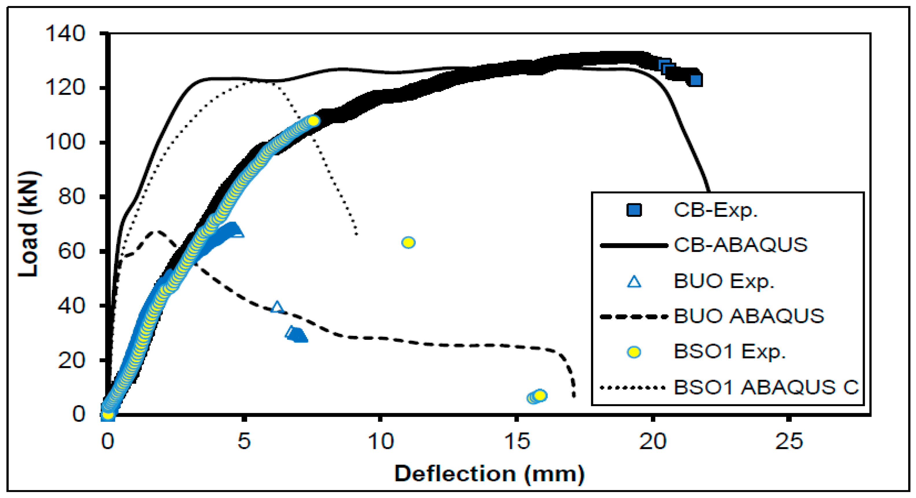
Figure 3 shows a comparison of the load–deflection curves of the experimental and numerical data for validation. Both load–deflection curves for CB began in the elastic zone, and progressed through strain hardening and softening. The two BUO curves followed a similar trend, as they behaved elastically prior to the first crack and then demonstrated a dramatic load reduction after reaching the ultimate load. For BSO1, the FEA and experimental curves both climbed linearly until the ultimate load had been reached, at which point the load was abruptly reduced. However, all load–deflection curves generated using FEA had a greater slope in the linear–elastic stage than that in the experimental observations. According to Mansour [53], and Ogbolugogo et al. [54], the FEA curve’s steeper slope may have been due to the interaction between the BFRP plate and concrete. A comparison between the perfect bond and cohesive contact assumptions was also modelled in this work. The cohesive contact assumption improved the prediction accuracy, with an error reduction of up to 3.2%. Thus, the FEA in this work was performed using the cohesive contact assumption except for those cases without a strengthening or control beam. Ogbologugo et al. [54] further asserted that the steeper slope from FEA could have been a result of the machine’s stiffness, and the emergence of microcracks within the concrete as a result of drying shrinkage and handling. In conclusion, the FEA and experimental load–deflection curves for all beam models had comparable load–deflection trends and showed reasonable agreement, especially on the ultimate load value. Thus, the FEA model was fairly accurate and could be used further to evaluate various strengthening configurations.
The FEA’s ultimate load prediction and the experimental measurement for RC beams with openings in shear were compared according to Al-bared and Marto [55], and this is summarised in Table 7. The CB and BUO were both not strengthened and hence were not affected by the cohesive or perfect bond assumption. The error in this case was decreased from 16.7% under the perfect bond assumption to 13.43% under the cohesive element model. The rig used for experimental measurements by Chin et al. [4] had an average standard deviation of about 6%. Since the prediction was relatively comparable to the experimental measurement, the FEA RC beam models developed in this work had adequate reliability and precision for predicting external strengthening with BFRP [55].
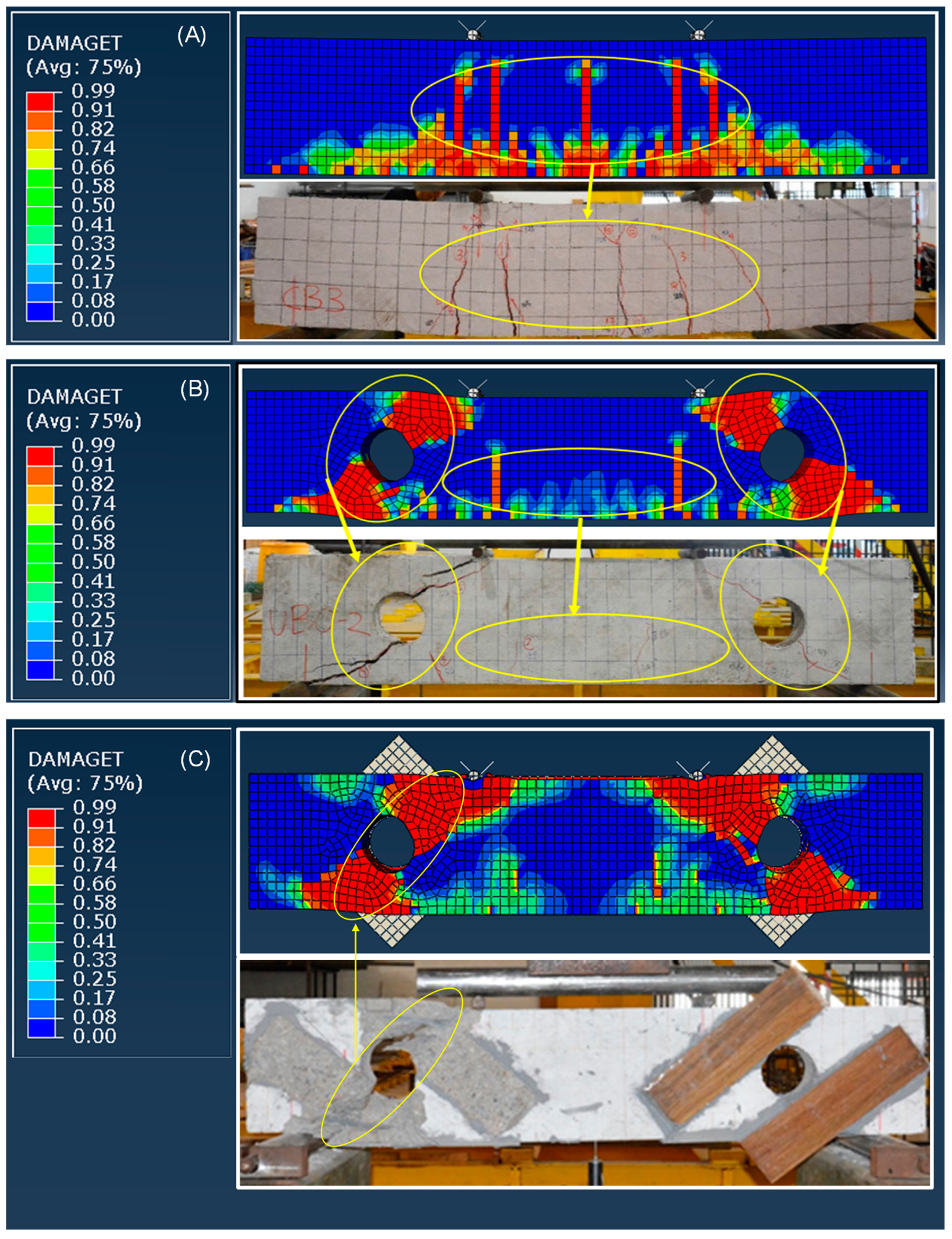
Flexural cracks first developed in the tension zone of the CB’s midspan. With increasing stress, the flexural cracks vertically propagated upwards to the compression zone. As the load increased, the cracks continued to develop and propagate towards the roller supports. The CB failed as a result of the tension steel reinforcement yielding. On the basis of the fracture pattern, numerical and experimental CBs exhibited ductile flexural failure, as shown in Figure 4A. BUO failed the shear test, as shown in Figure 4B, with two diagonal cracks extending from the roller supports to the loading point. The diagonal crack began at the circular openings and continue to extend diagonally towards the beam’s tension and compression zones as the load was continuously increased. Simultaneously, flexural cracks were found in the beam’s tension zone. As the stress increased, the concrete was crushed at the loading point and roller support, indicating the beam’s ultimate failure. The brittle behaviour of BUO was due to the existence of shear openings that disrupted the beam’s natural load path, concentrating stress around the openings and producing diagonal cracks. BSO1 also exhibited shear failure at the openings and midspan, as shown in Figure 4C, with shear cracks and fine flexural cracks. BSO1 had a similar fracture pattern to that of BUO, but due to the ideal bond assumption for the contact between the BFRP plate and concrete in numerical BSO1, the debonding of the BFRP plate observed in the experimental BSO1 was not captured in the modelled BSO1. In conclusion, all experimental and FEA beams exhibited identical crack patterns. This result demonstrates that the numerical beam models were validated satisfactorily and could be further used to evaluate various strengthening configurations.
3.1.2. Load–Deflection and Crack Pattern of Flexural Strengthened RC Beam
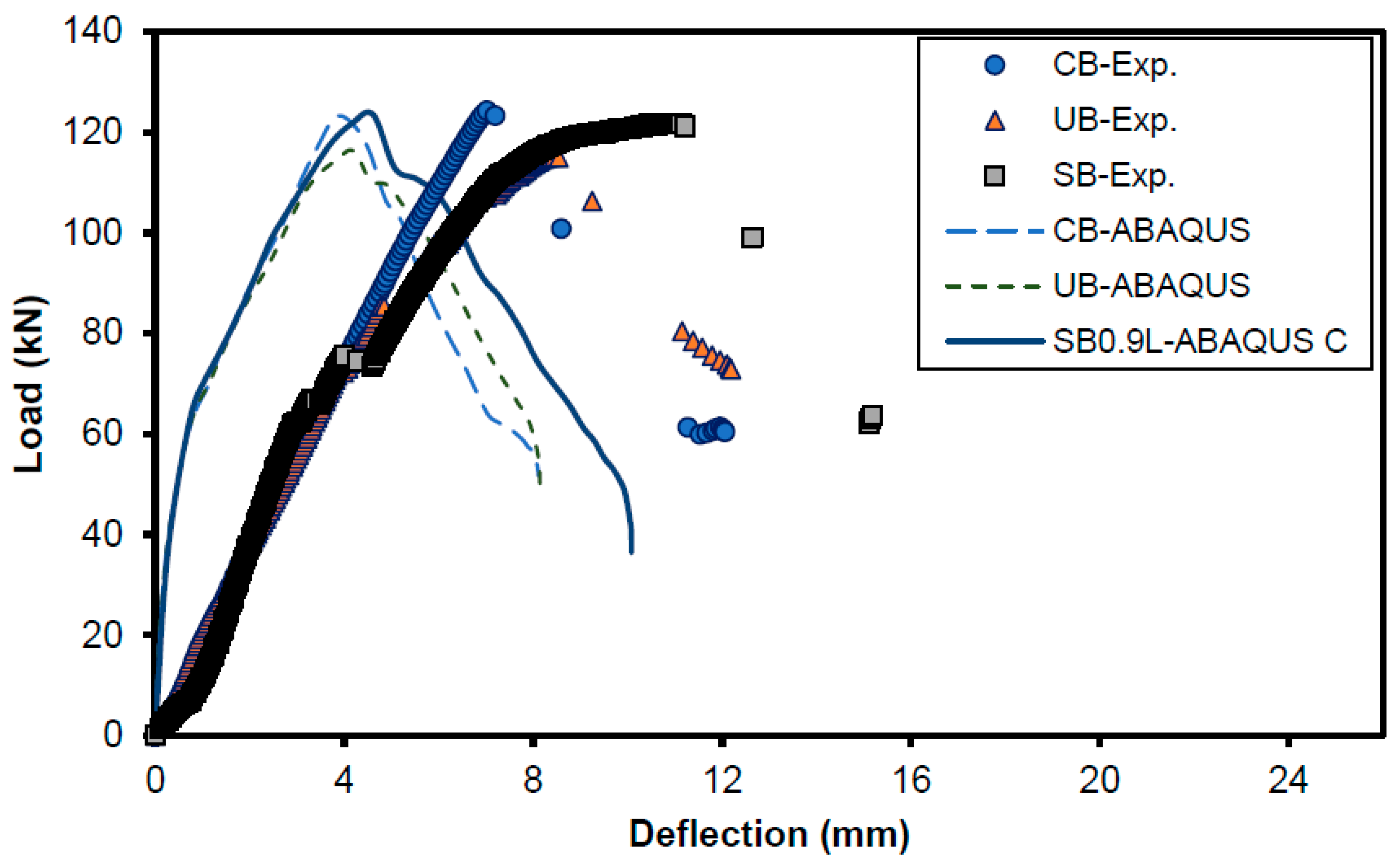
Figure 5 shows the comparison of the load–deflection curve from experimental measurement and FEA. Numerical CB, UB, and SB results indicated a steeper slope during the elastic stage compared to the experimental measurement. This could be attributable to the model’s assumption of complete bonding between the concrete beam and the steel reinforcement. Moreover, the bond slip between the concrete beam and steel reinforcement could account for the slope’s steepness. Additionally, microcracks inside the cementitious material and machine stiffness [54] contributed to the discrepancy in steepness. After the elastic stage, the numerical curves reached the inelastic stage during which they exhibited ductile behaviour due to strain hardening. At that point, the curve exhibited a comparable inelastic gradient to that observed in the experimental measurements. After reaching their peak strength, the numerical and experimental curves exhibited identical strain-softening gradients that were characteristic of brittle behaviour. Generally, the FEA results are in fair agreement with the experimental results, especially regarding ultimate load-bearing capacity. Finite-element-modelled and experimentally observed load–deflection curves exhibited similar patterns.
Table 8 shows the comparison of the predicted and experimentally measured ultimate load-bearing capability of RC beams in flexure. The FEA accurately predicted the ultimate load-bearing capability of the specimen with an average error of about 1.13%. Therefore, the FEA RC beam models developed in this work are dependable and sufficiently accurate. The difference between the error of the predicted ultimate load-bearing capability for a reinforced beam in flexure between the perfect bond and cohesive contact assumptions was not significant. However, as mentioned earlier, the load–deflection curve prediction obtained from the cohesive contact assumption was closer to the experimental measurement than that obtained from the perfect bond model. Hence, a parametric study was performed using the cohesive contact model.
First, fine and short cracks were observed in the CB’s midspan. Vertical cracks first occurred approximately 500 mm from the beam’s edge as the load increased. As the additional incremental load was applied, diagonal cracks developed towards the loading points and supports. The two diagonal cracks propagated diagonally towards the supports and loading points. A few microcracks were formed along the beam’s midspan in both the FEA and the experiment. The experimental beam crack patterns and the ABAQUS-generated crack map of the control beam (CB) at beam failure are shown in Figure 6. Although UB cracks are similar to CB cracks in terms of growth and propagation, more fine cracks were seen at the beam’s midspan, along with slightly larger diagonal and vertical cracks, because the beam’s flexural zone was not reinforced with stirrups for UB. SB had fewer cracks along the beam’s midspan than those of UB because the strengthening of BFRP plates in SB mitigates crack formation and propagation. The majority of vertical cracks are deflected away from the strengthened zone, while diagonal cracks grow towards loading points and support, eventually resulting in the beam failing in shear. In terms of fracture propagation and failure mode, the crack patterns of the numerical findings were in fair agreement with the experimental observations for CB, UB, and SB0.9L, as shown in Figure 6. Major experimentally observed crack lines were also reproduced numerically.
3.2. Parametric Study
3.2.1. Strengthening Configuration of RC Beam with Openings in Shear with BFRP
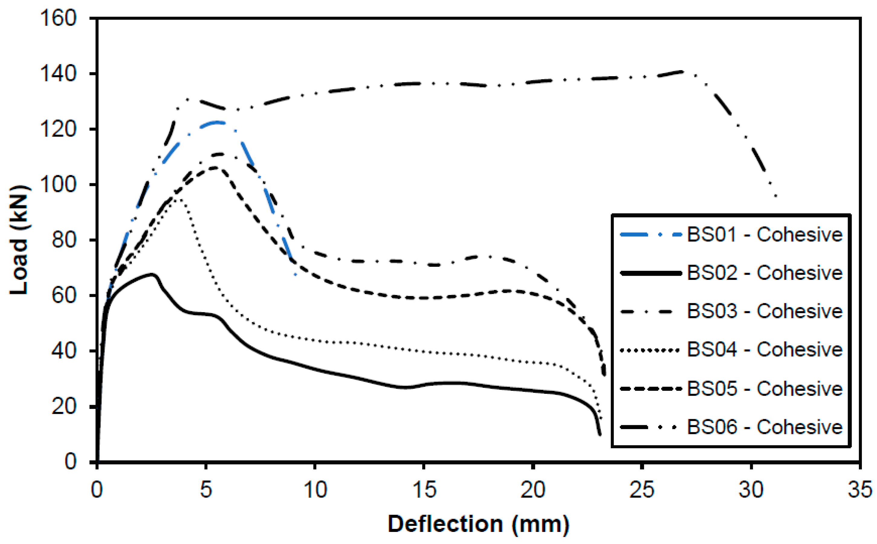
Figure 7 shows the load–deflection curve for all beams with openings strengthened using a BFRP plate in various configurations. All beams except BSO6, with BFRP plates strengthened on both sides of the beam surface in a perpendicular direction to the crack, demonstrated brittle failure. BSO6 exhibited similar ductile properties to those of CB.
BSO1, BSO2, BSO3, BSO4, BSO5, and BSO6 exhibited comparable initial tangent stiffness at 59.74, 59.25, 59.04, 62.87, 61.81, and 60.32 kN, respectively. All the beams started to crack at a deflection from 0.5 to 0.7 mm. After the initial crack had been initiated, the load on BSO1, BSO2, BSO3, BSO4, and BSO5 continued to build until the ultimate load had been reached, at which point they failed abruptly with quick load reduction. According to the simulation results, BSO2 and BSO4 failed prior to the steel yielding. In the case of BSO6, the load continued to increase beyond the end of linear elastic behaviour until it had reached 130.38 kN at a deflection of 4.06 mm; then, the load steadily increased due to the strain hardening behaviour. It ultimately failed at 140 kN with a deflection of 27.16 mm. BSO6 indicated ductile behaviour.
The ultimate load for BSO6 was 140 kN, followed by 122.34 kN for BSO1, 105.65 kN for BSO3, 105.66 kN for BSO5, 94.60 kN for BSO4, and 67.55 kN for BSO2. This comparison demonstrates that the most effective strengthening configuration for a beam with openings at the shear zone is to place the BFRP plate perpendicular to the crack on both sides of the beam’s surface. In the case of BSO2, the effect of BFRP strengthening was insignificant because the BSO2 load was just 0.27% greater than the BUO load (unstrengthened beam with opening). Thus, aligning the BFRP plate parallel to the fracture did not contribute to strengthening the beam with shear openings.
Figure 8 shows the load–deflection curves of CB, BUO, and BSO6. CB and BSO6 exhibited ductile behaviour with a gradual increase in load preceding beam failure, whereas BUO exhibited brittle behaviour with a sudden fall in load before beam collapse. This demonstrates an improvement in the strengthening strategy compared to the prior study by Chin et al. [4], who successfully transformed the behaviour of the RC beam with openings in shear from brittle into ductile, which is more desirable in terms of structural member safety.
The cracking, yielding, and ultimate loads, and associated deflections for the three beams are summarised in Table 9. CB had the largest cracking load, followed by BSO6 and BUO. When the external strengthening of the BFRP plate was applied, a 7.94% increase in yielding load was observed. This demonstrates the benefit of using BSO6 in a strengthening configuration on a beam with openings in shear. BSO6 had the highest ultimate load, followed by CB and BUO. Additionally, the ultimate load-carrying capacity of BUO drastically dropped, by 47.14%, due to the reduction in the cross-sectional area of the beam caused by the openings. This conclusion is consistent with the findings in [4,56,57,58] that determined that, for a beam with large openings at 0.4 d, the load-carrying capacity of the beam is reduced by at least 26%. However, by employing BFRP plate strengthening in a similar configuration to that of BSO6, the beam could restore its original load-carrying capability of CB by 110.06%, which represents a 10.06% increase in load-carrying capacity compared to the control beam.
Figure 8 shows that the maximal deflection values for CB, BUO, and BSO6 dropped from 31.32 mm for BSO6 to 22.11 mm for CB, and 17.10 mm for BUO. According to El Ame et al. [1], a beam is ductile if it can undergo significant plastic deformation before failing. The reduction in maximal deflection due to the presence of openings in BUO was consistent with that previously reported by El Ame et al. [1]. BSO6 exhibited a greater maximal deflection than that of CB, implying that it was more ductile. Thus, the strengthening configuration of BSO6 was effective, as it not only restored ductility to the beam with openings in shear, but also enhanced its ductility compared to CB.
3.2.2. Strengthening Configuration of RC Beam with BFRP in Flexure
Length of BFRP Plate
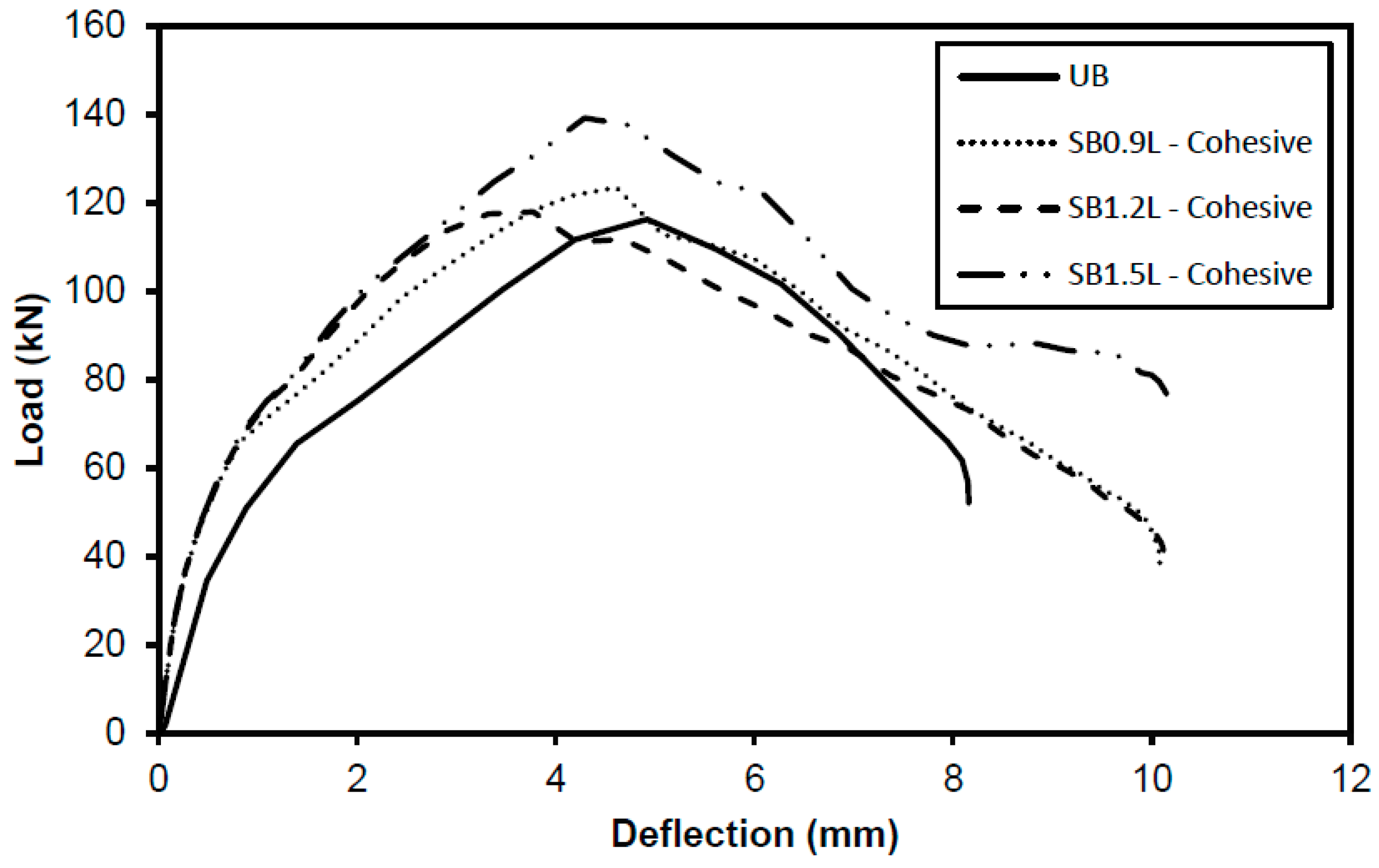
To examine the effect of BFRP plate length on the flexure of an RC beam, a BFRP plate with three different lengths of 900, 1200, and 1500 mm was modelled. When UB was strengthened with a single BFRP plate that spanned the whole length and width of the beam (SB1.5L), it exhibited the stiffest elastic slope among the modelled beams. It attained its ultimate load-bearing capacity of 139.23 kN with a deflection of 4.29 mm, which corresponded to a 19.7% improvement compared to UB. This enhancement, however, came at a loss of beam ductility. SB1.5L had a significant decrease in ductility with a failure deflection of 8.18 mm. SB0.9L increased the ultimate load-bearing capacity of UB by 6.18%, which is 123.51 kN. However, increasing the length of the BFRP plate to 1200 mm resulted in a negligible increase in ultimate load-bearing capacity by SB1.2L, as shown in Figure 9. Generally, strengthening the entire bottom soffit of the beam with the BFRP plate resulted in the greatest increase in load-bearing capability.
BFRP Plate Width
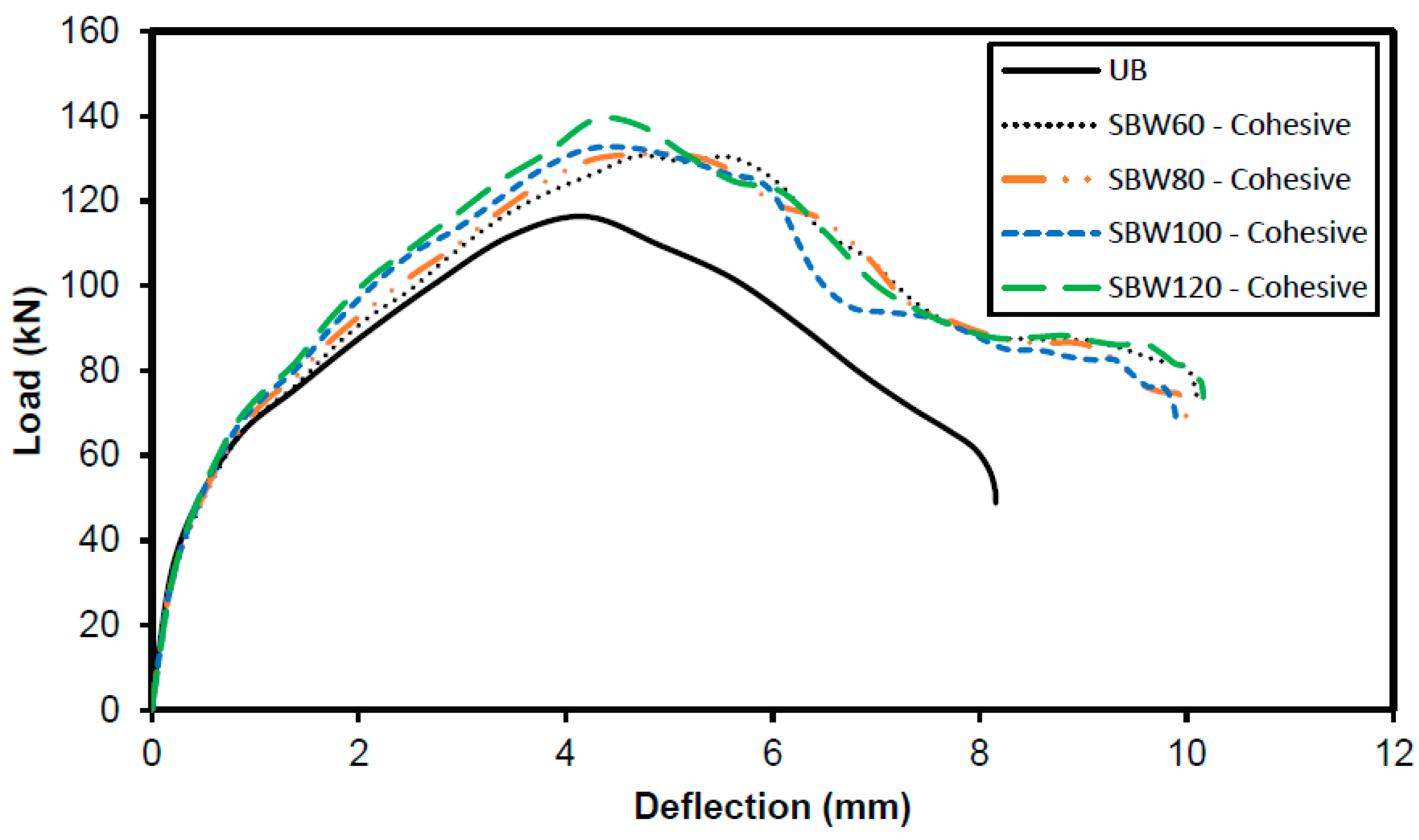
The SB1.5L achieved the greatest increase in ultimate load-bearing capability. Thus, the 1500 mm long BFRP plate was used for the remainder of the parametric investigation. Plate widths ranging from 60 to 120 mm were investigated. Figure 10 shows that a BFRP plate with a width of 120 mm (SB120W) covering the entire width of the beam had the greatest increase in ultimate strength, up to 19.70%. SB60W, SB80W, and SB100W all provided a small improvement in ultimate strength when deflected by an average of 4.68 mm. The width of the BFRP plate had a minimal effect on the ultimate strength of the RC beam.
Thickness of BFRP Plate
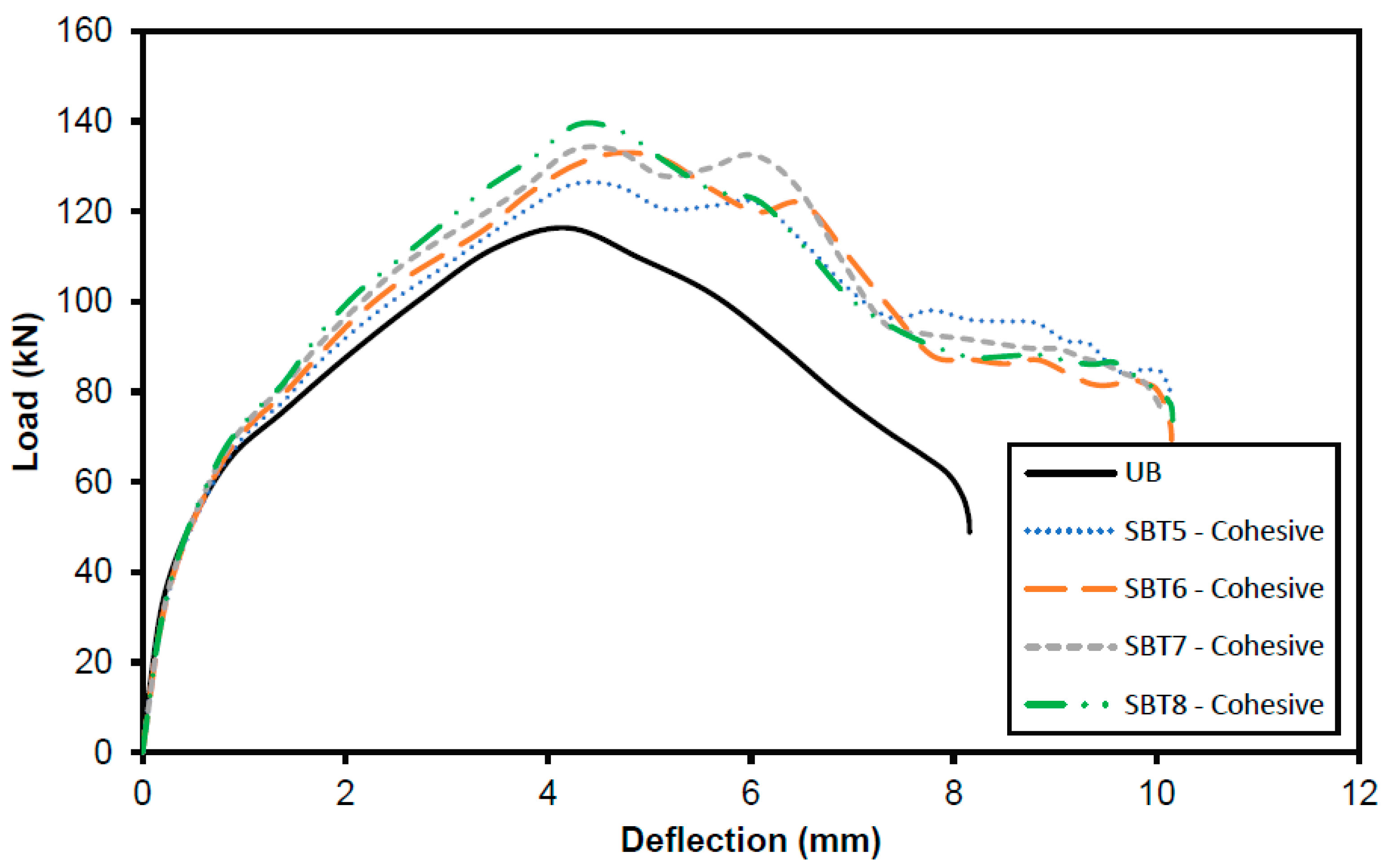
A further parametric investigation was performed using BFRP plates with thicknesses of 5, 6, 7, and 8 mm to strengthen the UB. The SB8T (8 mm plate) attained the highest ultimate strength of 139.23 kN, while the SB5T (5 mm plate) only slightly improved the ultimate strength of UB, to 126.05 kN (Figure 11). Increases in plate thickness often improve the ultimate strength of RC beams, but at the expense of the beam’s ductility.
4. Conclusions
The FEA results agreed well with the experimental measurements. The beams’ load–deflection curves and crack patterns matched the experimental data. However, the beam was predicted to be somewhat stiffer during its elastic behaviour in FEA due to the interaction between the BFRP plate and concrete. In the experimental investigation, only a limited configuration was tested because of difficulties in casting the beams and preparing sufficient BFRPs for each test, which needed to be replicated thrice. However, in FEA, it was possible to cost-efficiently test various configurations without casting the actual beams. The most effective strengthening configuration for a beam with openings in shear was to place BFRP plates on both sides of the beam’s surface with a perpendicular orientation to the fracture (BSO6). BSO6 increased the beam’s original load-bearing capability by 10.06% compared to CB, and that of the unstrengthened beam with an opening (BUO) by 108.18%. The FEA enabled an effective beam-strengthening configuration with BFRP, which was not discovered during the experimental investigation when the tested configuration could only regain up to 98% of the original beam capacity. However, with FEA, it was possible to study more configurations, resulting in a greater load-bearing amount (140.25 kN) than that of the original beam (127.43 kN). Additionally, this strengthening method contributed to the transition of the beam with openings in shear from shear into flexural failure, thereby increasing structural safety. The most effective arrangement for strengthening the RC beam in flexure was to bond the BFRP plate to the RC beam’s entire bottom soffit. This resulted in the greatest increase in ultimate load, but at the expense of the beam’s ductility.
Author Contributions
Conceptualization, S.C.C., J.N.S. and Q.Y.T.; methodology, J.N.S., Q.Y.T., S.C.C., K.S.L. and J.G.; validation, J.N.S., Q.Y.T., K.F.T. and S.C.C.; formal analysis, J.N.S., Q.Y.T., K.S.L. and S.C.C.; investigation, J.N.S., Q.Y.T. and S.C.C.; resources, S.C.C., K.F.T. and J.G.; data curation, J.N.S., Q.Y.T. and S.C.C.; writing—original draft preparation, J.N.S., Q.Y.T. and S.C.C.; writing—review and editing, S.C.C., J.G. and K.F.T.; supervision, S.C.C.; project administration, S.C.C.; funding acquisition, S.C.C. All authors have read and agreed to the published version of the manuscript.
Funding
This research was funded by Universiti Malaysia Pahang, grant number RDU1803105.
Institutional Review Board Statement
Not applicable.
Informed Consent Statement
Not applicable.
Data Availability Statement
Experimental data used in this manuscript is available from the electronic supplementary material of Chin et al. [4] at https://doi.org/10.1617/s11527-020-01572-y. Meanwhile, the FEA simulation is self-contained in this manuscript.
Acknowledgments
The authors gratefully acknowledge the lab assistance and facilities provided by the Faculty of Civil Engineering Technology Laboratory of Universiti Malaysia Pahang.
Conflicts of Interest
The authors declare no conflict of interest.
References
- El Ame, F.; Mwero, J.N.; Kabubo, C.K. Openings Effect on the Performance of Reinforced Concrete Beams Loaded in Bending and Shear. Eng. Technol. Appl. Sci. Res. 2020, 10, 5352–5360. [Google Scholar] [CrossRef]
- Salawdeh, S.G.S. Design of Reinforced Concrete Beams with Web Openings. Civ. Eng. Res. Irel. 2020, 3, 2020. [Google Scholar]
- Mansur, M.A. Design of Reinforced Concrete Beams with Web Openings. In Proceedings of the 6th Asia-Pacific Structural Engineering and Construction Conference, Kuala Lumpur, Malaysia, 5–6 September 2006. [Google Scholar]
- Chin, S.C.; Tee, K.F.; Tong, F.S.; Doh, S.I.; Gimbun, J. External strengthening of reinforced concrete beam with opening by bamboo fiber reinforced composites. Mater. Struct. 2020, 53, 1–12. [Google Scholar] [CrossRef]
- Gizachew, A.P.; Makebo, M. Contracts for Durable Concrete Structures: A Case Study. Int. J. Aquat. Sci. 2021, 12, 955–962. [Google Scholar]
- Sen, T.; Reddy, H.J. Strengthening of RC beams in flexure using natural jute fibre textile reinforced composite system and its comparative study with CFRP and GFRP strengthening systems. Int. J. Sustain. Built Environ. 2013, 2, 41–55. [Google Scholar] [CrossRef]
- Yang, J. Strengthening Reinforced Concrete Structures with FRP Composites Strengthening Reinforced Concrete Structures with FRP Composites Department of Architecture and Civil Engineering; Chalmers University of Technology: Gothenburg, Sweden, 2021. [Google Scholar]
- Manoj, A.; Sathyan, D. Strengthening of concrete square column using FRP composites. J. Phys. Conf. Ser. 2021, 2070, 012206. [Google Scholar] [CrossRef]
- Asyraf, M.R.M.; Khan, T.; Syamsir, A.; Supian, A.B.M. Synthetic and Natural Fiber-Reinforced Polymer Matrix Composites for Advanced Applications. Materials 2022, 15, 6030. [Google Scholar] [CrossRef] [PubMed]
- Bazli, M.; Heitzmann, M.; Hernandez, B.V. Durability of fibre-reinforced polymer-wood composite members: An overview. Compos. Struct. 2022, 295, 115827. [Google Scholar] [CrossRef]
- Abbood, I.S.; Odaa, S.A.; Hasan, K.F.; Jasim, M.A. Properties evaluation of fiber reinforced polymers and their constituent materials used in structures—A review. Mater. Today Proc. 2020, 43, 1003–1008. [Google Scholar] [CrossRef]
- Madhavi, K.; Harshith, V.; Gangadhar, M.; Kumar, V.C.; Raghavendra, T. External strengthening of concrete with natural and synthetic fiber composites. Mater. Today Proc. 2020, 38, 2803–2809. [Google Scholar] [CrossRef]
- Nwankwo, C.O.; Mahachi, J.; Olukanni, D.O.; Musonda, I. Natural fibres and biopolymers in FRP composites for strengthening concrete structures: A mixed review. Constr. Build. Mater. 2023, 363. [Google Scholar] [CrossRef]
- Sen, T.; Reddy, H.J. Efficacy of bio derived jute FRP composite based technique for shear strength retrofitting of reinforced concrete beams and its comparative analysis with carbon and glass FRP shear retrofitting schemes. Sustain. Cities Soc. 2014, 13, 105–124. [Google Scholar] [CrossRef]
- Haufe, J.; Carus, M. Hemp Fibres for Green Products—An Assessment of Life Cycle Studies on Hemp Fibre Applications; nova-Institut GmbH: Hürth, Germany, 2011. [Google Scholar]
- Barth, M.; Carus, M. Multi Hemp Carbon Footprint and Sustainability of Different Natural Fibres for Biocomposites and Insulation Material; nova-Institut GmbH: Hürth, Germany, 2015. [Google Scholar]
- Zwawi, M. A Review on Natural Fiber Bio-Composites; Surface Modifications and Applications. Molecules 2021, 26, 404. [Google Scholar] [CrossRef]
- Uz Zaman, A.; A Gutub, S.; Soliman, M.F.; Wafa, M.A. Sustainability and human health issues pertinent to fibre reinforced polymer composites usage: A review. J. Reinf. Plast. Compos. 2014, 33, 1069–1084. [Google Scholar] [CrossRef]
- Ivanova, I.; Assih, J.; Dontchev, D. Investigation of the Mechanical Behavior of Natural Vegetable Fibers Used in Composite Materials for Structural Strengthening. Key Eng. Mater. 2021, 888, 15–21. [Google Scholar] [CrossRef]
- Karimah, A.; Ridho, M.R.; Munawar, S.S.; Adi, D.S.; Ismadi; Damayanti, R.; Subiyanto, B.; Fatriasari, W.; Fudholi, A. A review on natural fibers for development of eco-friendly bio-composite: Characteristics, and utilizations. J. Mater. Res. Technol. 2021, 13, 2442–2458. [Google Scholar] [CrossRef]
- Ku, H.; Wang, H.; Pattarachaiyakoop, N.; Trada, M. A review on the tensile properties of natural fiber reinforced polymer composites. Compos. Part B Eng. 2011, 42, 856–873. [Google Scholar] [CrossRef]
- Balakrishnan, T.S.; Sultan, M.T.H.; Naveen, J.; Shahar, F.S.; Najeeb, M.I.; Shah, A.U.M.; Khan, T.; Sebaey, T.A. Selection of Natural Fibre for Pultruded Hybrid Synthetic/Natural Fibre Reinforced Polymer Composites Using Analytical Hierarchy Process for Structural Applications. Polymers 2022, 14, 3178. [Google Scholar] [CrossRef] [PubMed]
- Zhang, K.; Wang, F.; Liang, W.; Wang, Z.; Duan, Z.; Yang, B. Thermal and Mechanical Properties of Bamboo Fiber Reinforced Epoxy Composites. Polymers 2018, 10, 608. [Google Scholar] [CrossRef] [PubMed]
- Wasti, S.; Kore, S.; Yeole, P.; Tekinalp, H.; Ozcan, S.; Vaidya, U. Bamboo fiber reinforced polypropylene composites for transportation applications. Front. Mater. 2022, 9, 967512. [Google Scholar] [CrossRef]
- Lotfi, A.; Li, H.; Dao, D.V.; Prusty, G. Natural fiber–reinforced composites: A review on material, manufacturing, and machinability. J. Thermoplast. Compos. Mater. 2019, 34, 238–284. [Google Scholar] [CrossRef]
- Tong, F.S.; Chin, S.C.; Doh, S.I.; Gimbun, J. Natural Fiber Composites as Potential External Strengthening Material—A Review. Indian J. Sci. Technol. 2017, 10, 1–5. [Google Scholar] [CrossRef]
- Begum, M.; Islam, K. Natural Fiber as a substitute to Synthetic Fiber in Polymer Composites: A Review. Res. J. Eng. Sci. 2013, 2, 46–53. [Google Scholar]
- Radzi, A.; Zaki, S.A.; Hassan, M.Z.; Ilyas, R.A.; Jamaludin, K.R.; Daud, M.Y.M.; Aziz, S.A. Bamboo-Fiber-Reinforced Thermoset and Thermoplastic Potential Applications. Polymers 2022, 14, 1387. [Google Scholar] [CrossRef]
- Kamarudin, S.H.; Basri, M.S.M.; Rayung, M.; Abu, F.; Ahmad, S.; Norizan, M.N.; Osman, S.; Sarifuddin, N.; Desa, M.S.Z.M.; Abdullah, U.H.; et al. A Review on Natural Fiber Reinforced Polymer Composites (NFRPC) for Sustainable Industrial Applications. Polymers 2022, 14, 3698. [Google Scholar] [CrossRef]
- Chaowana, K.; Wisadsatorn, S.; Chaowana, P. Bamboo as a Sustainable Building Material—Culm Characteristics and Properties. Sustainability 2021, 13, 7376. [Google Scholar] [CrossRef]
- Zhang, W.; Wang, C.; Gu, S.; Yu, H.; Cheng, H.; Wang, G. Physical-Mechanical Properties of Bamboo Fiber Composites Using Filament Winding. Polymers 2021, 13, 2913. [Google Scholar] [CrossRef]
- Raja, D.B.P.; Retnam, B.S.J.; Bhusan, J.K.; Rajadhas, J.E. Experimental Investigation of Hybrid Bamboo/Glass Fibre Reinforced Polyester Composites. Elixir Mater. Sci. 2018, 119, 51189–51192. [Google Scholar]
- Chandrasekaran, S.; Sato, N.; Tölle, F.; Mülhaupt, R.; Fiedler, B.; Schulte, K. Fracture toughness and failure mechanism of graphene based epoxy composites. Compos. Sci. Technol. 2014, 97, 90–99. [Google Scholar] [CrossRef]
- Awoyera, P.O.; Nworgu, T.A.; Shanmugam, B.; Arunachalam, K.P.; Mansouri, I.; Romero, L.M.B.; Hu, J.-W. Structural Retrofitting of Corroded Reinforced Concrete Beams Using Bamboo Fiber Laminate. Materials 2021, 14, 6711. [Google Scholar] [CrossRef]
- Nwankwo, C.O.; Ede, A.N. Flexural strengthening of reinforced concrete beam using a natural fibre reinforced polymer laminate: An experimental and numerical study. Mater. Struct. 2020, 53, 1–13. [Google Scholar] [CrossRef]
- Alam, M.A.; Al Riyami, K. Shear strengthening of reinforced concrete beam using natural fibre reinforced polymer laminates. Constr. Build. Mater. 2017, 162, 683–696. [Google Scholar] [CrossRef]
- Alam, M.A.; Nouri, K.; Jumaat, M.Z.; Muda, Z.C. Flexural strengthening of reinforced concrete beam using jute rope compo-site plate. In Proceedings of the 3rd National Graduate Conference (NatGrad2015), Kajang, Malaysia, 8–9 April 2015; pp. 210–213. [Google Scholar]
- Hafizah, N.A.K.; Bhutta, M.A.R.; Jamaludin, M.Y.; Warid, M.H.; Ismail, M.; Rahman, M.S.; Yunus, I.; Azman, M. Kenaf Fiber Reinforced Polymer Composites for Strengthening RC Beams. J. Adv. Concr. Technol. 2014, 12, 167–177. [Google Scholar] [CrossRef]
- Sen, T.; Jagannatha Reddy, H.N. Pretreatment of woven jute FRP composite and its use in strengthening of reinforced concrete beams in flexure. Adv. Mater. Sci. Eng. 2013, 2013, 128158. [Google Scholar] [CrossRef]
- Singh, S.P.; Dutt, A.; Hirwani, C.K. Experimental and numerical analysis of different natural fiber polymer composite. Mater. Manuf. Process. 2022, 38, 322–332. [Google Scholar] [CrossRef]
- Qiu, Z.; Fan, H. Nonlinear modeling of bamboo fiber reinforced composite materials. Compos. Struct. 2020, 238, 111976. [Google Scholar] [CrossRef]
- Hidayat, B.A.; Hu, H.-T.; Han, A.L.; Haryanto, Y.; Widyaningrum, A.; Pamudji, G. Nonlinear finite element analysis of traditional flexural strengthening using betung bamboo (Dendrocalamus asper) on concrete beams. IOP Conf. Ser. Mater. Sci. Eng. 2019, 615, 012073. [Google Scholar] [CrossRef]
- Sen, T.; Reddy, H.N.J. A Numerical Study of Strengthening of RCC Beam using Natural Bamboo Fibre. Int. J. Comput. Theory Eng. 2011, 3, 707–713. [Google Scholar] [CrossRef]
- CEB-FIP. Design of Concrete Structures. CEB-FIP Model Code 1990; Thomas Telford Services Ltd.: Lausanne, Switzerland, 1993. [Google Scholar]
- Walraven, J.C.; Van Der Horst, A.Q.C. Fib Model Code for Concrete Structures 2010; John Wiley & Sons: Hoboken, NJ, USA, 2013. [Google Scholar]
- Malm, R. Predicting shear type crack initiation and growth in concrete with non-linear finite element method. Ph.D. Thesis, KTH Royal Institute of Technology, Stockholm, Sweden, 2009. [Google Scholar]
- Abaqus 6.14 Theory Manual, Dassault Systemes Simulia, Inc.: Vélizy-Villacoublay, France, 2014.
- Agarwal, B.D.; Broutman, L.J.; Chandrashekhara, K. Analysis and Performance of Fiber Composites, 3rd ed.; John Wiley & Sons, Ltd.: Hoboken, NJ, USA, 1981; ISBN 978-0-471-26891-8. [Google Scholar]
- Chin, S.C.; Tee, K.F.; Tong, F.S.; Ong, H.R.; Gimbun, J. Thermal and mechanical properties of bamboo fiber reinforced composites. Mater. Today Commun. 2019, 23, 100876. [Google Scholar] [CrossRef]
- Ruamcharoen, P.; Umaree, S.; Ruamcharoen, J. Relationship between Tensile Properties and Morphology of Epoxy Resin Modified by Epoxidised Natural Rubber. J. Mater. Sci. Eng. 2011, 5, 504–510. [Google Scholar]
- Tysmans, T.; Wozniak, M.; Remy, O.; Vantomme, J. Finite element modelling of the biaxial behaviour of high-performance fibre-reinforced cement composites (HPFRCC) using Concrete Damaged Plasticity. Finite Elem. Anal. Des. 2015, 100, 47–53. [Google Scholar] [CrossRef]
- Obaidat, Y.T.; Heyden, S.; Dahlblom, O. The effect of CFRP and CFRP/concrete interface models when modelling retrofitted RC beams with FEM. Compos. Struct. 2010, 92, 1391–1398. [Google Scholar] [CrossRef]
- Mansour, W. Numerical analysis of the shear behavior of FRP-strengthened continuous RC beams having web openings. Eng. Struct. 2020, 227, 111451. [Google Scholar] [CrossRef]
- Ogbologugo, U.; Saidani, M.; Olubanwo, A.O.; Coakley, E. Finite element analysis of the flexural behaviour of steel-reinforced GEM-TECH cementitious material. Eng. Solid Mech. 2018, 263–274. [Google Scholar] [CrossRef]
- Al-Bared, M.A.M.; Marto, A. Evaluating the Compaction Behaviour of Soft Marine Clay Stabilized with Two Sizes of Recycled Crushed Tiles; GCEC 2017; Lecture Notes in Civil Engineering; Pradhan, B., Ed.; Springer: Singapore, 2019; Volume 9. [Google Scholar]
- Shoeib, A.E.-K.; Sedawy, A.E.-S. Shear strength reduction due to introduced opening in loaded RC beams. J. Build. Eng. 2017, 13, 28–40. [Google Scholar] [CrossRef]
- Latha, M.S.; Naveen Kumar, B.M. Behavior of reinforced concrete beam with opening. Int. J. Civ. Eng. Technol. 2017, 8, 581–593. [Google Scholar]
- Shubbar, A.; Alwan, H.; Phur, E.Y.; Mcloughlin, J.; Al-Khaykan, A. Studying the Structural Behaviour of RC Beams with Cir-cular Openings of Different Sizes and Locations Using FE Method. Int. J. Struct. Constr. Eng. 2017, 11, 916–919. [Google Scholar]
Figure 1.
Reinforcement detailing of RC beam with openings in shear.

Figure 2.
Reinforcement detailing of RC beam without shear links in flexure.

Figure 3.
Load–deflection plot of CB, BUO, and BSO1. Experimental data from Chin et al. [4].
Figure 3.
Load–deflection plot of CB, BUO, and BSO1. Experimental data from Chin et al. [4].

Figure 4.
Comparison of the crack patterns of the FEA and the experiment [4] for (A) CB, (B) BUO, and (C) BSO1.
Figure 4.
Comparison of the crack patterns of the FEA and the experiment [4] for (A) CB, (B) BUO, and (C) BSO1.

Figure 5.
Load–deflection plot of CB, UB, and SB. The experimental data points were adopted from Chin et al. [4].
Figure 5.
Load–deflection plot of CB, UB, and SB. The experimental data points were adopted from Chin et al. [4].

Figure 6.
Experimental [4] and ABAQUS-generated crack patterns for (A) CB, (B) UB, and (C) SB0.9L.
Figure 6.
Experimental [4] and ABAQUS-generated crack patterns for (A) CB, (B) UB, and (C) SB0.9L.

Figure 7.
Load–deflection curves for BSO Abaqus.

Figure 8.
Comparison of the load–deflection curves for Abaqus CB, BUO, and BSO6.

Figure 9.
Load–deflection behaviour of flexural strengthened RC beams with different BFRP plate lengths.
Figure 9.
Load–deflection behaviour of flexural strengthened RC beams with different BFRP plate lengths.

Figure 10.
Load–deflection behaviour of flexural strengthened RC beams with different widths of BFRP plate.
Figure 10.
Load–deflection behaviour of flexural strengthened RC beams with different widths of BFRP plate.

Figure 11.
Load–deflection behaviour of flexural strengthened RC beams with different BFRP plate thicknesses.
Figure 11.
Load–deflection behaviour of flexural strengthened RC beams with different BFRP plate thicknesses.


Table 1.
Adopted constitutive model for concrete in compression and tension.
| Compression | where | |
| Tension | in mm when when |
Note: represents the secant modulus from the origin to the peak compressive stress, represents the strain corresponding to the peak compressive stress, represents the crack opening in mm, represents the fracture energy in N/mm.
| Plastic Flow Potential | Yield Surface | Viscosity Parameter | ||
|---|---|---|---|---|
Table 3.
Properties of steel reinforcement from Chin et al. [4].
Table 3.
Properties of steel reinforcement from Chin et al. [4].
| Density | Elastic Modulus | Poisson’s Ratio | Yield Stress | |
|---|---|---|---|---|
| Rebar | 7.85 g/cm3 | 210 GPa | 0.3 | 450 MPa |
| Stirrup | 7.85 g/cm3 | 210 Gpa | 0.3 | 225 MPa |
Table 4.
Properties of epoxy and bamboo fibres.
| Density (g/cm3) | Elastic Modulus, (GPa) | Poisson’s Ratio | Reference | |
|---|---|---|---|---|
| Epoxy | 1.16 | 2.2 | 0.36 | [49] |
| Bamboo | 0.89 | 27.93 | 0.30 | [48,50] |
Table 5.
Details of beams modelled in this research for Group A.
| Beam | Strengthening Configuration | Analysis |
|---|---|---|
| CB | - | Experiment and FEA |
| BUO | - | Experiment and FEA |
| BSO1 | BFRP perpendicular to the crack | Experiment and FEA |
| BSO2 | BFRP parallel to the crack | FEA |
| BSO3 | BFRP surrounding the openings | FEA |
| BSO4 | BFRP is located at the left and right of the openings | FEA |
| BSO5 | BFRP is located at the top and bottom of the openings | FEA |
| BSO6 | BFRP perpendicular to the crack at both sides surface | FEA |
Table 6.
Details of beams modelled in this work for Group B.
| Beam | Strengthening Configuration | Analysis |
|---|---|---|
| CB | - | Experiment and FEA |
| UB | - | Experiment and FEA |
| SB0.9L | 900 mm length of BFRP at the bottom soffit of the beam | Experiment and FEA |
| SB1.2L | 1200 mm length of BFRP at the bottom soffit of the beam | FEA |
| SBP1.5L | 1500 mm length of BFRP at the bottom soffit of the beam | FEA |
| SB60W | 60 mm width of BFRP at the bottom soffit of the beam | FEA |
| SB80W | 80 mm width of BFRP at the bottom soffit of the beam | FEA |
| SB100W | 100 mm width of BFRP at the bottom soffit of the beam | FEA |
| SB120W | 120 mm width of BFRP at the bottom soffit of the beam | FEA |
| SB5T | 5 mm thickness of BFRP at the bottom soffit of the beam | FEA |
| SB6T | 6 mm thickness of BFRP at the bottom soffit of the beam | FEA |
| SB7T | 7 mm thickness of BFRP at the bottom soffit of the beam | FEA |
| SB8T | 8 mm thickness of BFRP at the bottom soffit of the beam | FEA |
Table 7.
Comparison of the ultimate load-bearing capacity of RC beams with openings in shear FEA and the experiment.
Table 7.
Comparison of the ultimate load-bearing capacity of RC beams with openings in shear FEA and the experiment.
| Beam Specimen | Assumption | Ultimate Load-Bearing Capacity (kN) | Error (%) | |
|---|---|---|---|---|
| FEA | Experiment | |||
| CB | - | 127.43 | 131.23 | 2.90 |
| BUO | - | 67.37 | 68.66 | 1.89 |
| BSO1 | Perfect bond | 125.82 | 107.85 | 16.67 |
| BSO1 | Cohesive | 122.34 | 107.85 | 13.43 |
Table 8.
Comparison of the FEA and experimental ultimate load-bearing capacity of RC beams in flexure [4].
Table 8.
Comparison of the FEA and experimental ultimate load-bearing capacity of RC beams in flexure [4].
| Beam Specimen | Ultimate Load-Bearing Capacity (kN) | Error (%) | ||
|---|---|---|---|---|
| Assumption | FEA | Experiment | ||
| CB | - | 122.98 | 124.24 | 1.01 |
| UB | - | 116.32 | 115.11 | 1.05 |
| SB0.9L | Perfect bond | 122.89 | 121.70 | 0.98 |
| SB0.9L | Cohesive | 123.51 | 121.70 | 1.49 |
Table 9.
Predicted cracking, yielding, and ultimate loads of CB, BUO, and BSO6.
| Beam | Cracking | Yielding | Ultimate | |||
|---|---|---|---|---|---|---|
| Load (kN) | Deflection (mm) | Load (kN) | Deflection (mm) | Load (kN) | Deflection (mm) | |
| CB | 67.83 | 0.47 | 120.79 | 3.08 | 127.43 | 16.44 |
| BUO | 56.00 | 0.46 | - | - | 67.37 | 1.78 |
| BSO6 | 60.32 | 0.48 | 130.38 | 4.06 | 140.25 | 27.16 |
Disclaimer/Publisher’s Note: The statements, opinions and data contained in all publications are solely those of the individual author(s) and contributor(s) and not of MDPI and/or the editor(s). MDPI and/or the editor(s) disclaim responsibility for any injury to people or property resulting from any ideas, methods, instructions or products referred to in the content. |
© 2023 by the authors. Licensee MDPI, Basel, Switzerland. This article is an open access article distributed under the terms and conditions of the Creative Commons Attribution (CC BY) license (https://creativecommons.org/licenses/by/4.0/).
Share and Cite
MDPI and ACS Style
Siew, J.N.; Tan, Q.Y.; Lim, K.S.; Gimbun, J.; Tee, K.F.; Chin, S.C. Effective Strengthening of RC Beams Using Bamboo-Fibre-Reinforced Polymer: A Finite-Element Analysis. Fibers 2023, 11, 36. https://doi.org/10.3390/fib11050036
AMA Style
Siew JN, Tan QY, Lim KS, Gimbun J, Tee KF, Chin SC. Effective Strengthening of RC Beams Using Bamboo-Fibre-Reinforced Polymer: A Finite-Element Analysis. Fibers. 2023; 11(5):36. https://doi.org/10.3390/fib11050036
Chicago/Turabian StyleSiew, Jia Ning, Qi Yan Tan, Kar Sing Lim, Jolius Gimbun, Kong Fah Tee, and Siew Choo Chin. 2023. "Effective Strengthening of RC Beams Using Bamboo-Fibre-Reinforced Polymer: A Finite-Element Analysis" Fibers 11, no. 5: 36. https://doi.org/10.3390/fib11050036
Note that from the first issue of 2016, this journal uses article numbers instead of page numbers. See further details here.