
Damage Investigation on the Carbon Tows during Rewinding and Braiding Processes

1
Laboratoire de Génie et Matériaux, Gemtex, Ensait, University of Lille, F-59000 Roubaix, France 2 MBDA, F-18000 Bourges, France
2
MBDA, F-18000 Bourges, France
*
Author to whom correspondence should be addressed.
Fibers 2023, 11(3), 30; https://doi.org/10.3390/fib11030030
Submission received: 15 February 2023
/
Revised: 13 March 2023
/
Accepted: 15 March 2023
/
Published: 22 March 2023
(This article belongs to the Special Issue Fibers 10th Anniversary: Past, Present, and Future)
Abstract
:During the manufacturing process, the fibrous materials used in composite reinforcements are subjected to many sources of damage that must be managed if the best possible quality is to be reached for the final product. More specifically, carbon fibers are subjected, during reinforcement manufacturing, to friction with mechanical components and with other tows and to excessive tensile loads due to specific configurations required by textile devices, which results in degradation that affects their mechanical properties and those of final products. While many studies have focused on carbon tow damage during the weaving process, roving quality control during the post-braiding steps, such as the rewinding or braiding processes, is less studied in the literature. In this study, an experimental approach was developed to quantify the damage inflicted on 12 K carbon tows during the rewinding and braiding processes using image analysis software. Based on these images, a damage criterion is defined to quantify the influence of the parameters associated with rewinding and braiding processes on degradation of carbon tows. During the rewinding stage, the influence of the process parameters on the degradation by friction of the tows was significant, but the properties (linear density and tenacity) of these carbon tows were little-modified. On the other hand, the great influence of the tension applied on tows on the inflicted damage was experimentally demonstrated, during both the rewinding and braiding steps, which may have resulted in a loss of tenacity of up to 27%.
1. Introduction
Due to the advantages of the braiding process as a time- and cost-efficient manufacturing method that reduces carbon dioxide emissions and meets the growing demand for high-performance structures such as jet engine stator blades, fan blades, and shafts [1,2], braided composites are becoming more widely used for industrial applications.
Two-dimensional biaxial braids can be obtained by interweaving yarn around a mandrel using a maypole or radial braiding machines with different braid patterns; additional axial fibers can be introduced to produce triaxial-braided structures [3,4,5,6]. Considering the description of the braiding process, numerous studies have analytically linked the process parameters to the braid characteristics, such as the braiding angle or the cover factor [7,8,9]. The influence of these characteristics, the type of braids (biaxial or triaxial), and braid patterns on the mechanical properties of braided composites has been the subject of many works [6,9,10,11,12].
At the scale of braided composites, some applications based on carbon fibers are described in the literature. Wu et al. [13] experimentally and numerically studied the low-speed impact and axial compression behavior of composite tubes made from carbon braids, as a function of the number of layers. In investigating the axial crushing behavior of composite tubes reinforced by triaxial carbon braids, Mc Gregor et al. [14] showed the influence of the shape and dimensions of the section as well as the number of layers. Czichos et al. [15] investigated the influence of the parameters of the braiding process on the variability of parameters associated with biaxial carbon braids. C. Wang et al. [16] used image analysis (SEM, micro-CT) to explore the characteristics of the microstructure of composites made from carbon braids. Chai et al. [17] studied the damage evolution, using tomography, of biaxial-braided carbon composites during torsional loadings. These studies have shown that the braiding process must be controlled to minimize defects at composite and reinforcement scales, because braiding, as well as the weaving process, induces damage on yarn, which may result in a loss of tensile properties of carbon tows of up to 12% in the 3D weaving process, as shown by several authors [18,19,20,21].
For braiding, Ebel et al. [22] proposed a classification system to assess the level of damage to yarn, such as fiber breakage, damage to the surface or inside tows, and degradation of sizing, which modifies the cohesion of fibers. These types of damage increase when carbon fibers, which are brittle and easily broken, are used [15]. In response to these studies on the kinds of damage inflicted on carbon tows, modifications of braiding parameters to minimize this damage are also described, particularly during the braiding preparation steps. Y. Kyosev [23] described the importance of transferring yarn from storage bobbins to the yarn carriers and the regulation of tension during the steps of unwinding/winding, because all bobbins have to be wound with the same tension. Additionally, during the braiding process, the tension of tows must be kept equal for all carriers; if one carrier has a different tension, a spiral effect can occur, where the tows with a lower tension wind themselves around the others [23]. S. S. Roy et al. [24] studied these aspects in different parts during the braiding, such as the evolution of the tension in carbon tows between the carrier and braid fell point, as well as the influence of braid carrier tension on braid parameters (braiding angle or cover factor) and the effect of tow tension on the nesting effect between layers during over-braiding of carbon layers. These authors have shown that increasing the tension has an influence on the width of the tows, which may result in a decreased cover factor. A braid manufactured with higher tow tension exhibited better fabric consolidation, characterized by the percentage reduction of the braid thickness in the composite material.
Considering these state-of-the-art studies, we conducted an experimental study to analyze the damage inflicted on carbon tows during the steps of rewinding and braiding. The level of damage inflicted on carbon tows as a function of the set process parameters during these steps was analyzed with a damage criterion as defined using the image analysis method, alongside the evolution of textile properties (linear density, tenacity), relative to their initial values before braiding. The objective of this study was to optimize the process parameters to reduce material damage.
2. Materials and Methods
2.1. Carbon Tows
To study the degradation that occurs during the rewinding and braiding steps, 12 K carbon tows were used. Characterization of the textile and mechanical properties of these rovings was performed as follows. The thickness was measured using a thickness test bench, following the NF EN ISO 5084 standard [25]. The linear density was identified according to the NF G07-316 standard [26]. Tenacity and strain at break were characterized using an MTS Criterion Series 45 tensile test machine on five samples with a gauge length of 250 mm and a crosshead displacement rate of 10 mm/min, following the NF EN ISO 2062 standard [27]. These characteristics are given in Table 1, and were considered the reference properties for this material, which we compared with those obtained after the rewinding and braiding steps.
2.2. Rewinding Device
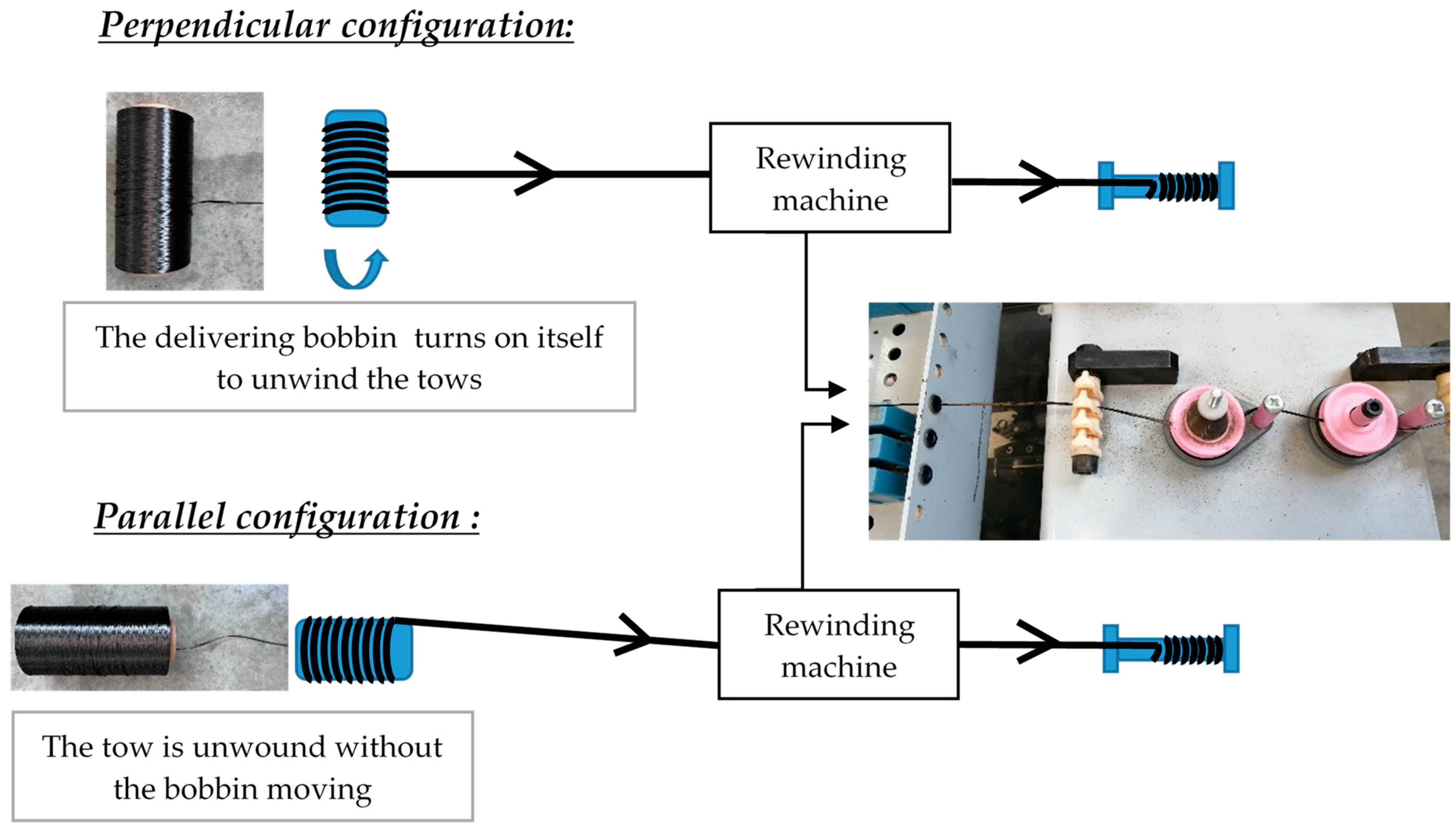
The degradation of carbon tows that occurs during the rewinding step was tested on a 2PVLU\220 Ratera® winding machine [28]. Two bobbins can be rewound simultaneously on this specific device. A potentiometer allows the user to control the speed at which the bobbin is rewound by increasing or decreasing the speed of rotation of the bobbin as well as the speed of displacement in putting the carbon tow on the bobbin. C. Cherif [29] showed that a low production speed may be more appropriate for brittle and fragile carbon-based products in order to minimize friction [30]. In this study, the influence of winding machine parameters on the degradation of carbon tows was investigated. Three parameters were considered: the speed used during rewinding and orientation (or placement) of the bobbin and angle (defining the position of the delivering bobbin) at which the tow is introduced into winding machine. For the orientation of the bobbin in relation to the winding machine, two configurations were considered. The concept of a winding machine is represented in Figure 1, with the two configurations of the bobbin orientation. When this bobbin is parallel to the axis of the winding machine, only the carbon tow is in a position to be unwound (configuration denoted as Parallel). If this bobbin is placed perpendicular to the axis of the winding machine, it then turns on itself to unwind the roving fed to the winding machine (configuration denoted as Perpendicular).
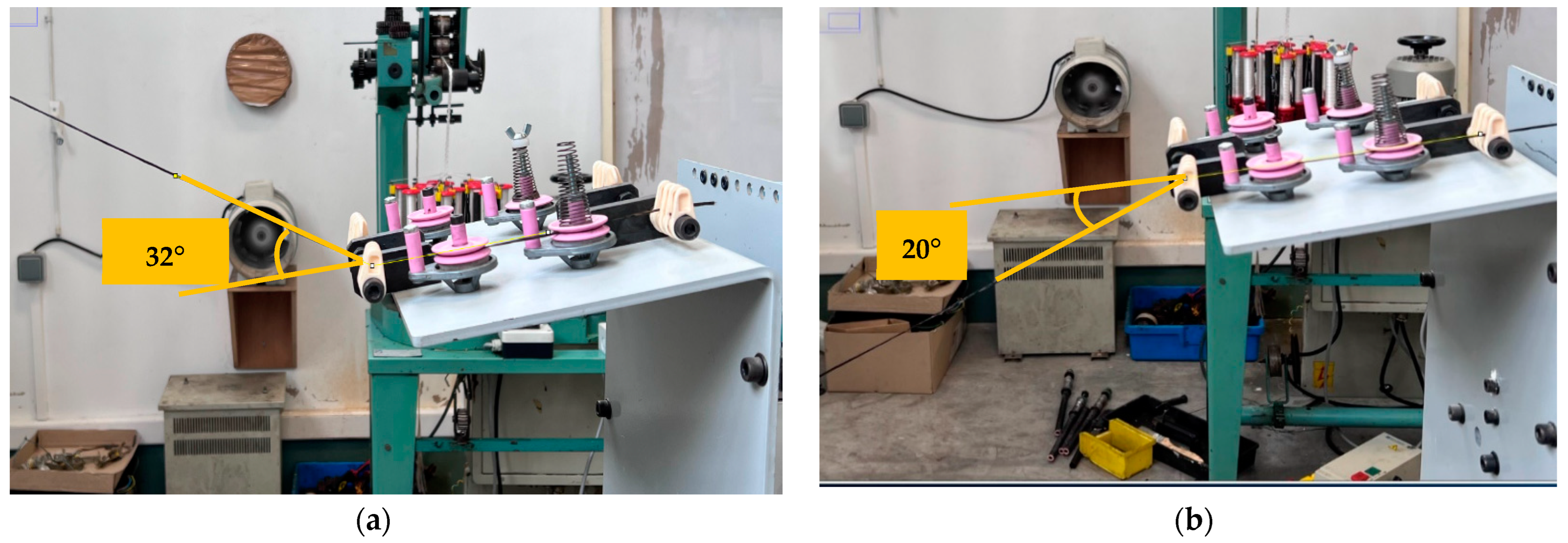
For the position of the delivering bobbin, two different angles were chosen. When the delivering bobbin is placed on the highest position of the creel, carbon tows enter into the winding machine at an angle of 32°, as shown in Figure 2a. In the lowest position of the creel, the carbon tows enter the winding machine at an angle of 20°, as shown in Figure 2b. The 32° angle is the highest value possible on this winding device, and will apply the most friction to the tows. The second position, associated with a lower angle (20°), is considered a more general rewinding configuration [23]. This position parameter was studied to analyze if the angle value applied during entry to the rewinding machine has a significant influence or not on the degradation of the tows.
For the applied speed used during rewinding, two configurations were considered: a low speed (configuration denoted as Low) and a high speed (configuration denoted as High). Following these different configurations, detailed in Table 2, an experiment was designed for the production of height samples. These samples are denoted, in the results section, with values used for each parameter. For example, the sample denoted as “32°-Low-Perpendicular” was rewound with an orientation perpendicular to the bobbin, with the delivering bobbin placed at the highest position at an angle of 32° on the creel and introduced at a low speed.
For each of these samples, the influence of these rewinding parameters on the degradation of carbon tows was analyzed. To complete the analysis, the tension applied to the tows during the rewinding process was monitored with a digital tensiometer placed after the entrance of the winding machine.
2.3. Braiding Process
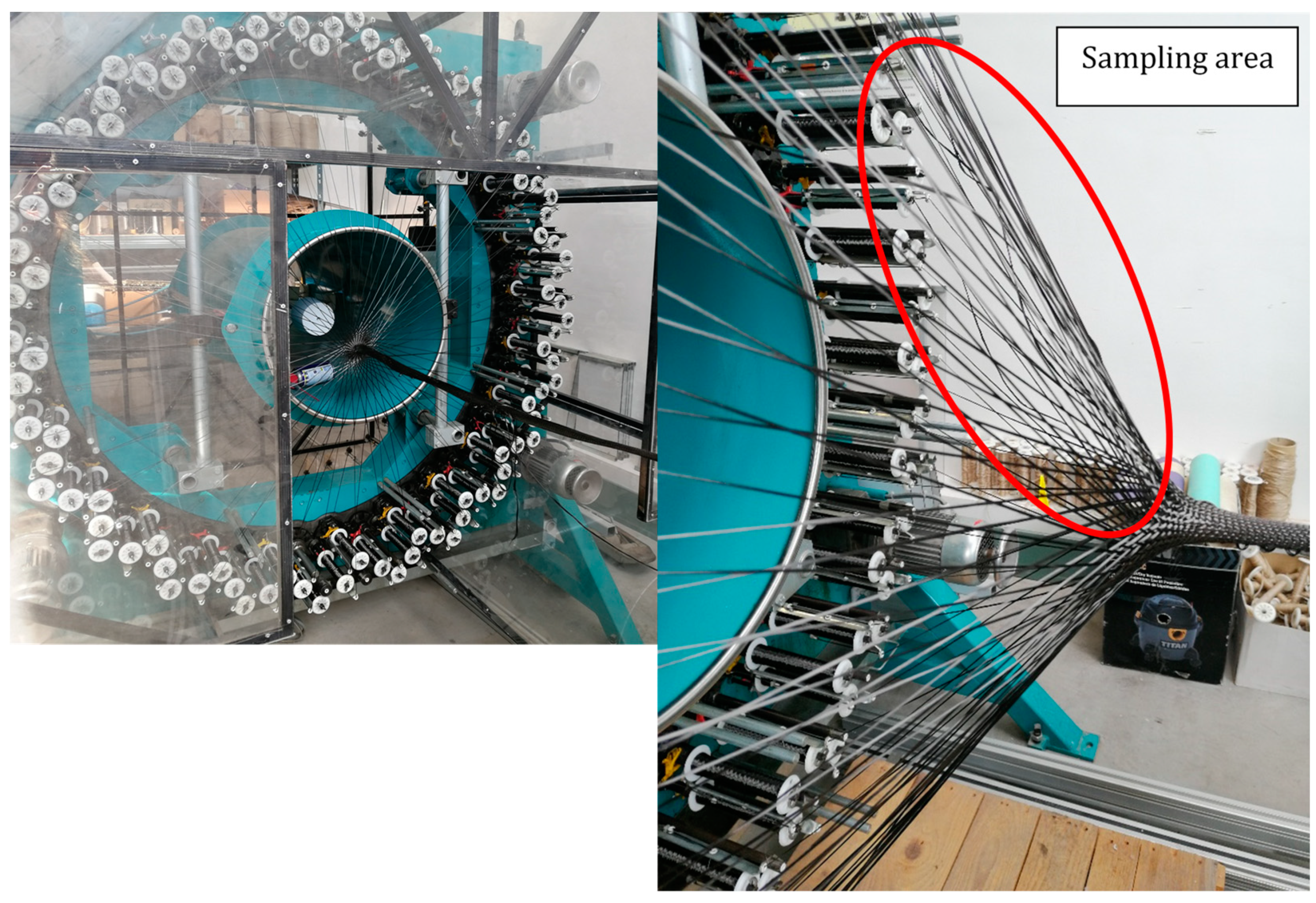
Once the carbon tows were rewound, the bobbins could be placed on the braiding machine. A HERZOG radial braiding machine with a capacity of 144 spools (96 and 48 for bias and axial tows, respectively) was used in the GEMTEX laboratory (Figure 3). It has been described in previous works [31,32,33,34]. As explained in the Introduction, tension plays a key role in the degradation of carbon tows and has an influence on braid parameters.
During the braiding process, the tension applied to the tows is controlled by the springs positioned inside the spools. The tension control system is driven by these springs. Therefore, the stiffer the spring, the greater the tension applied to the tows, which will result in greater friction with the braiding machine’s components, such as the eyelets. During the manufacture of the braid via the interlacing of the tows, friction occurs between them. It is essential to keep the tows stretched during the braiding process to prevent any inhomogeneity in the braiding angle or cover factor. Using he right springs, which should apply enough tension to produce a regular braid without excessive damage to the tows, is essential in the braiding process. Two types of springs were tested in this study for the production of braid samples: one that provides a tension of 115 cN, and a stiffer one that applies a tension of 200 cN. This braiding machine can fit a wide range of springs, from 30 cN to 950 cN. Due to the brittle quality of the carbon tows, these springs (115 cN and 200 cN) were chosen as they provided enough tension to keep the carbon tows stretched while being stiff enough to prevent tow breaks, which would stop the braiding process. S. S. Roy et al. [24] selected springs from the same range (150 cN and 300 cN) to braid carbon tows. The influence of these types of springs on the damage inflicted was analyzed at two scales; the purpose of this work was to compare the degradation of the tows between the output of the bobbin and the braiding point, as shown in Figure 3. In this sample zone, damage comes from the friction between the tows and braiding machine components and the friction between tows during the interlacing. In this zone, carbon tows were extracted, and their properties were compared, depending on the spring used, to their initial properties (given in Table 1). The kinds of damage inflicted were also analyzed at the scale of braids. From the carbon tows, two biaxial circular braids (denoted as Braid 1 and Braid 2) were produced with the same braiding parameters, except for the type of spring used in the bobbins. For their production, the carrier rotational speed and production speed were chosen as constants, and a braiding angle of 45° was used. Biaxial braids were manufactured with 96 carbon tows [31]. Characteristics of these braids and braiding parameters are given in Table 3. At this scale, the influence of the type of springs used on the defects in and damage inflicted on the braids produced was analyzed.
2.4. Analysis of Damages
Several methods can be used to analyze the degradation of carbon tows during the different stages of textile processes. The most frequently used methods are those based on image analysis methods to quantify carbon tow damage, from filament breaks on the edges of the carbon tows due to weak degradation to more critical breaks to the breaking of all the tows in the most severe cases [30]. To quantify the degradation and to be able to compare samples, Ebel et al. [30] proposed a classification system divided into five levels, from 0, when the tow is free of any defect, to 5, which corresponds to a complete break of the tow. Visual analysis can be performed with microscopic observations, or with scanned photos of the samples, provided that the contrast and quality of each photo are identical for all samples. However, while these methods provide an assessment of the surface condition of the tow, little information is available on the cross-section of tows or the consequence of degradation for the mechanical properties of tows. Other tests can be performed, such as mechanical characterization to follow the evolution of these properties (tensile or abrasion tests [35,36,37]) as well as local measurements to highlight material loss [22]. However, these methods require extraction and handling of the samples, which can increase degradation and therefore modify the results.
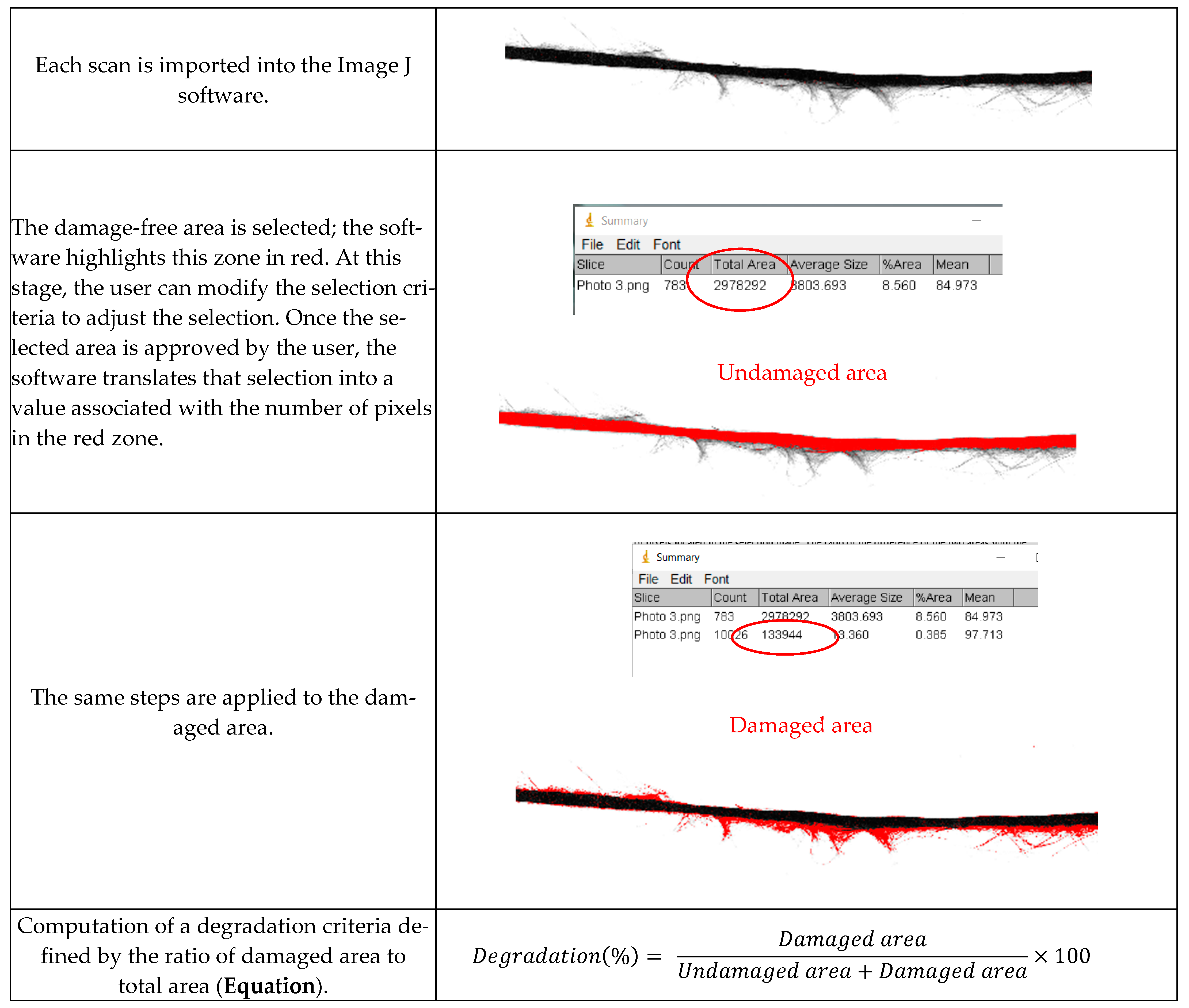
In this study, the samples were analyzed via image analysis and with tensile tests. Each tow sample was scanned at a resolution of 600 ppx. The images were then imported into the image processing software ImageJ [38]. The analysis was based on the damaged and non-damaged areas of the tow where no filament was broken or misaligned. The areas considered were highlighted in red by the software. Adjustments could be made manually to be as accurate as possible. Once the areas were selected, the software translated the selected surface into a value corresponding to the number of pixels located in the zone. The ratio of the area of damaged surface to the total surface considered allowed us to define a percentage of degradation of the tow occurring during the rewinding and braiding processes. The steps of this approach are described in Figure 4.
First, validations of the degradation criteria were performed for samples used in the rewinding step experiments (Table 2). For each configuration, five samples were considered, and degradation criteria were computed as an average over the length of each sample, and then averaged on these five samples, following the approach described in Figure 4. To study the accuracy of the method, samples with different damage levels were considered, and are presented in Table 4. For the initial tows, before rewinding, and considered without damage, the value of degradation reached 1.4%, which may indicate the accuracy of the method. For samples with increasing damage levels, the degradation criterion follows this trend with increasing values.
Following these first tests, for each configuration of carbon tows (depending on the parameters of the rewinding step or type of springs used during the braiding step), the percentage of degradation was evaluated for three samples, following the method described (Figure 4). The linear density and tenacity of tows after rewinding were measured and compared to the initial values given by the reference properties (Table 1).
3. Results and Discussion
3.1. Degradation during the Rewinding Step
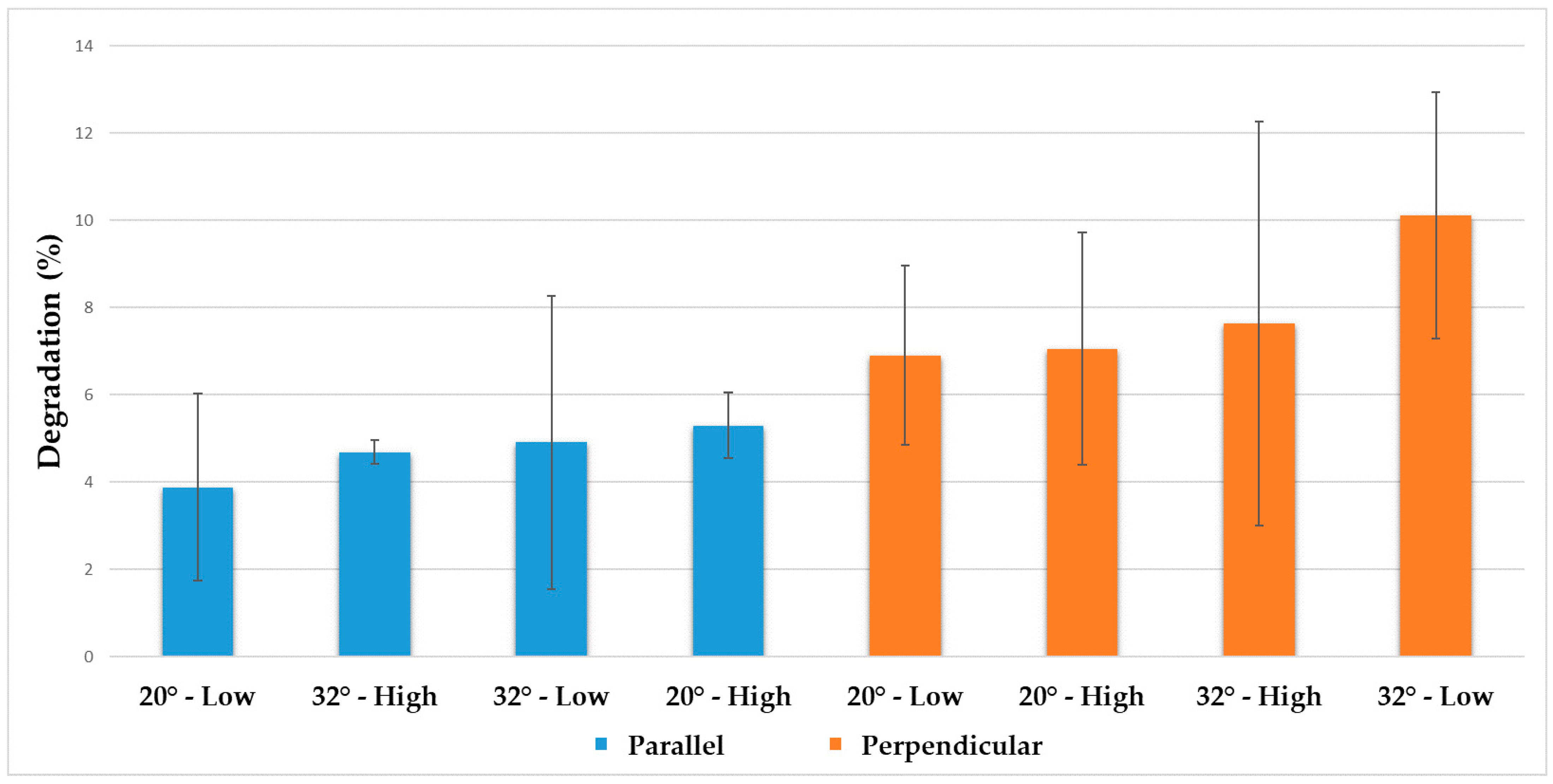
Following the designed experiment, as introduced previously (Table 2), Figure 5 shows the degradation criteria values, computed with Equation, for the height configurations, denoted with values of the three rewinding parameters used in this study.
Figure 5 shows that when the delivering bobbin was placed perpendicular to the axis of the winding machine (configuration in orange on the graph), a greater degradation was seen than when it was placed parallel to this axis (configuration in blue on the graph), regardless of the configurations of the speed or position parameters. In the parallel configuration, the delivering bobbin was aligned with the production axis. Therefore, the tows were free to unwind from the bobbin with no restriction. However, in the perpendicular configuration, the delivering bobbin had to roll in order to free the tows. Because the tows need to be transferred from the delivering bobbin to the receiving one, they were the ones driving the movement of the delivering bobbin. Therefore, the tows must be stretched and under tension during the rewinding process. The heavier the delivering bobbin is, the more tension is applied to the tows, increasing the rubbing of the tows against the guiding parts of the machine. This added friction results in a higher degradation percentage, in accordance with the observations made by Czichos [15] and the findings of several studies [18,19,20,21]. The highest position of the delivering bobbin (with an angle of 32°) seemed to increase the degradation of carbon tows, especially when this parameter was associated with a perpendicular orientation. Here, again, a higher angle value can be translated to higher stress for the carbon tows, and more friction where the angle is formed. The influence of rewinding speed (configurations: Low or High) seems to be low regardless of the other parameters.
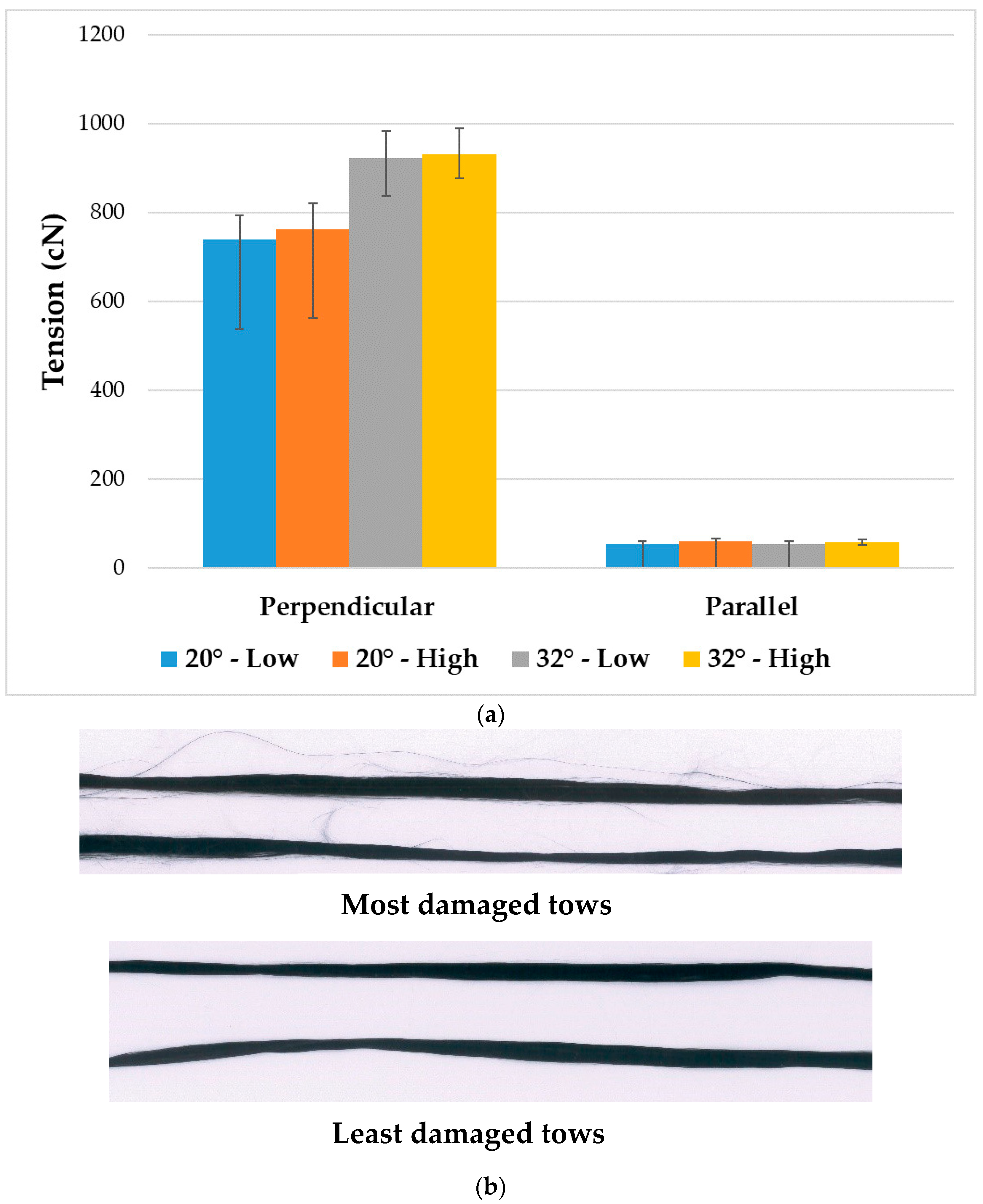
To explain this phenomenon, tension loads applied to the tows were measured using the digital tensiometer, placed after the entrance of the winding machine, as shown in Figure 6a.
Figure 6a shows that when the delivering bobbin was placed perpendicular to the axis of the winding machine, the weight of the bobbin provided additional tension for the roving, which was significant compared to the tension values measured when the delivering bobbin was placed parallel to this axis. As shown previously for the degradation criteria, an angle of 32°, associated with the highest position of the delivering bobbin, increases tension on carbon tows. Figure 6b shows carbon tows with two extreme values of the studied parameters after the rewinding step. For samples with the configuration “32°-Low-Perpendicular”, which had a higher value of the damage criterion, as shown in Figure 5, and higher tension applied on carbon tows, as shown in Figure 6a, the damage was clearly visible compared to samples with the configuration “20°-Low-Parallel”. These results show the link between the tension applied on carbon tows and the degradation occurring during this rewinding step.
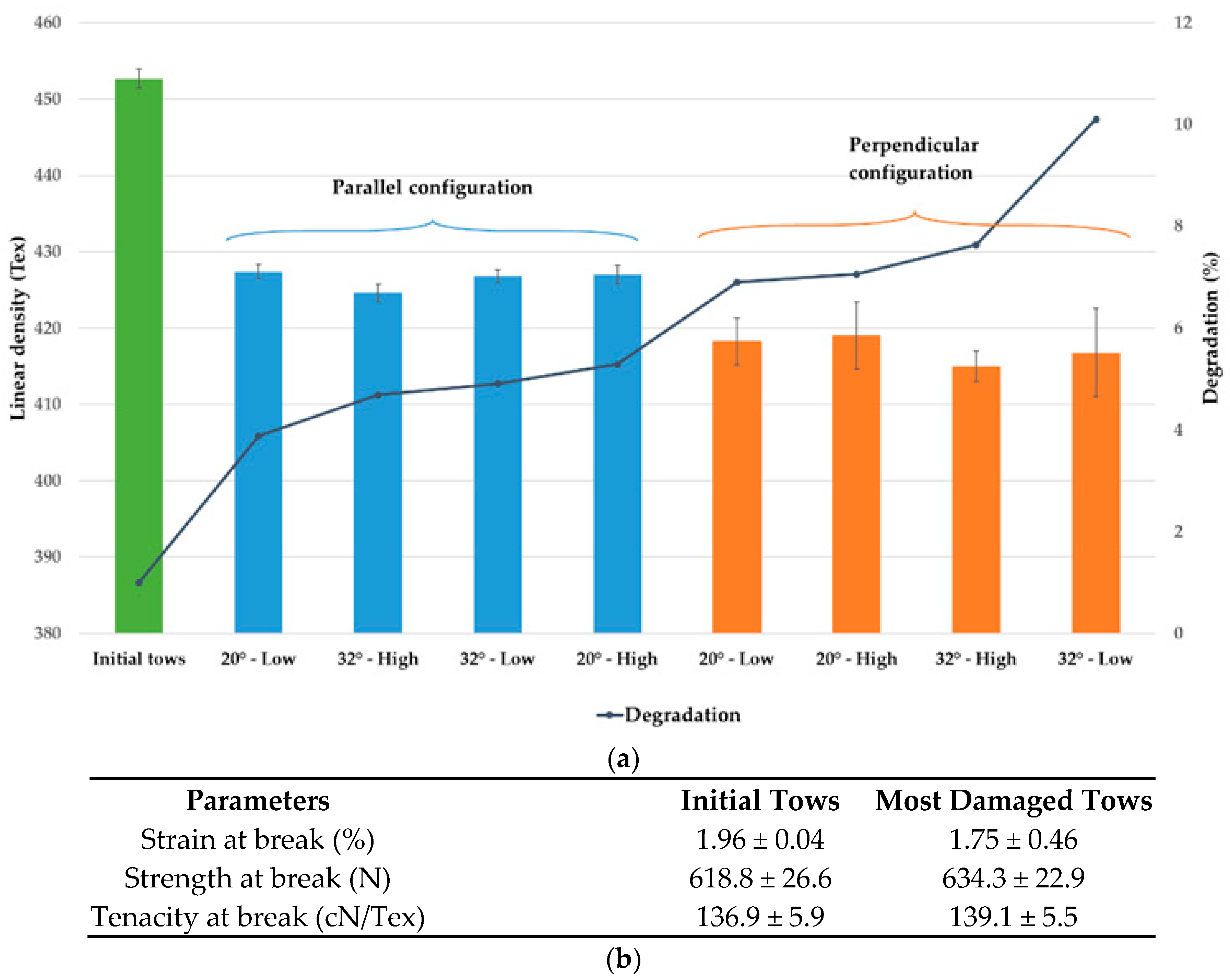
At the scale of tows, the level of damage was quantified with the measurement of the linear density and the tenacity at break of samples after rewinding. Figure 7a shows the comparison of the linear density of samples relative to the initial value before rewinding, as given in Table 1. The superposition on this curve (in black in Figure 7a) of the evolution of the degradation criterion shows a clear trend in the evolution of the linear density: the more the tows were damaged, the more the linear density decreased. For the most damaged samples, we observed a relative decrease of 6.3% in the yarn count. As shown in Figure 6b, the degradation of carbon tows took the form of filament breaks as well as surface fibrils due to friction, which indicates material loss and a decrease in the linear density of the tows. Figure 7b compares the tensile characteristics of the most damaged sample with that of the initial tows. We can deduce that the level of damage does not involve, at the tow scale, a significant decrease in mechanical properties.
These results show that during the rewinding step, the tension applied on carbon tows is a main factor affecting the degradation state of these tows. The damage was quantified using the definition of a degradation criterion, and mainly took the form of fibrils, fiber misalignments and fiber breaks, which can be consistent along the entire tow, but have little influence on the main properties of these tows, including the linear density and tenacity. On the other hand, this damage can increase during the following stages, in particular the braiding step.
3.2. Degradation during the Braiding Step
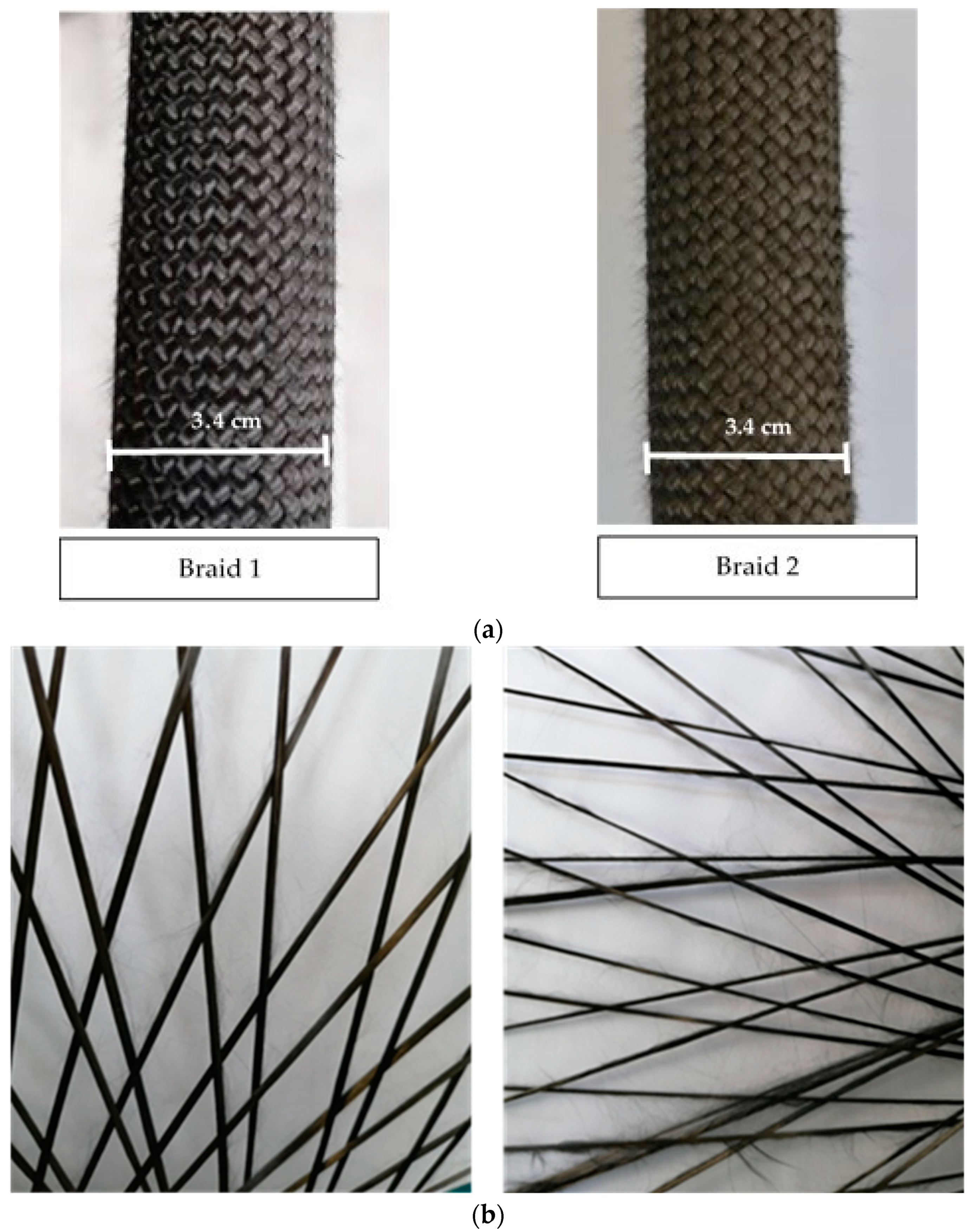
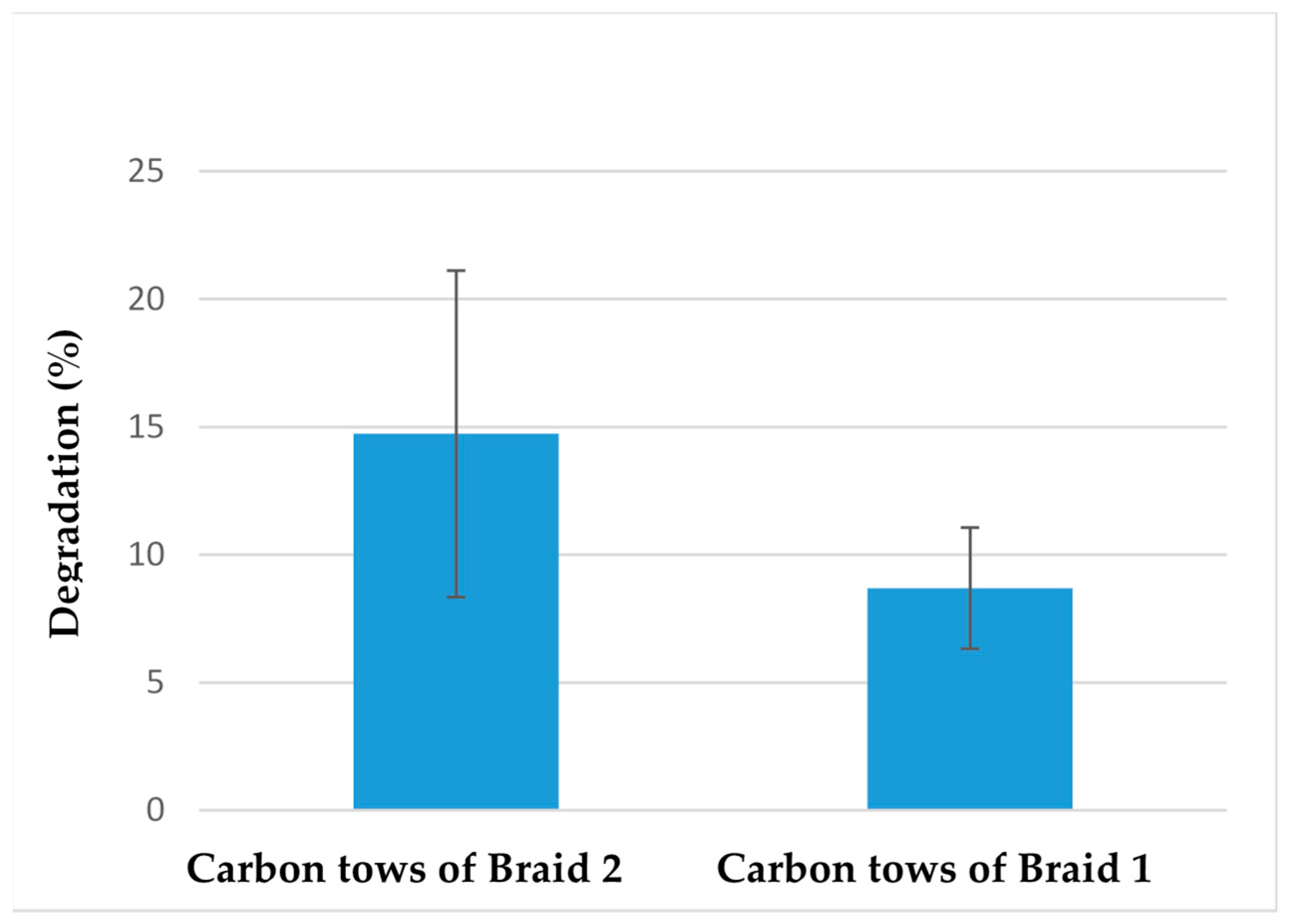
As presented in Section 2.3, two types of braids (Braid 1 and Braid 2) were manufactured with the braiding parameters given in Table 3, which differed in the springs used. Figure 8 shows the products obtained as well as the state of the carbon tows in the sampling area (defined Figure 3). We can clearly note a difference between the two products. Compared to Braid 1, for Braid 2, which was manufactured with stiffest springs, the carbon tows were under a higher tension and had more fibrils or misalignments of fibers (Figure 8b). The corresponding braid (Braid 2) was hairier, with a lot of fibrils on its surface (Figure 8a).
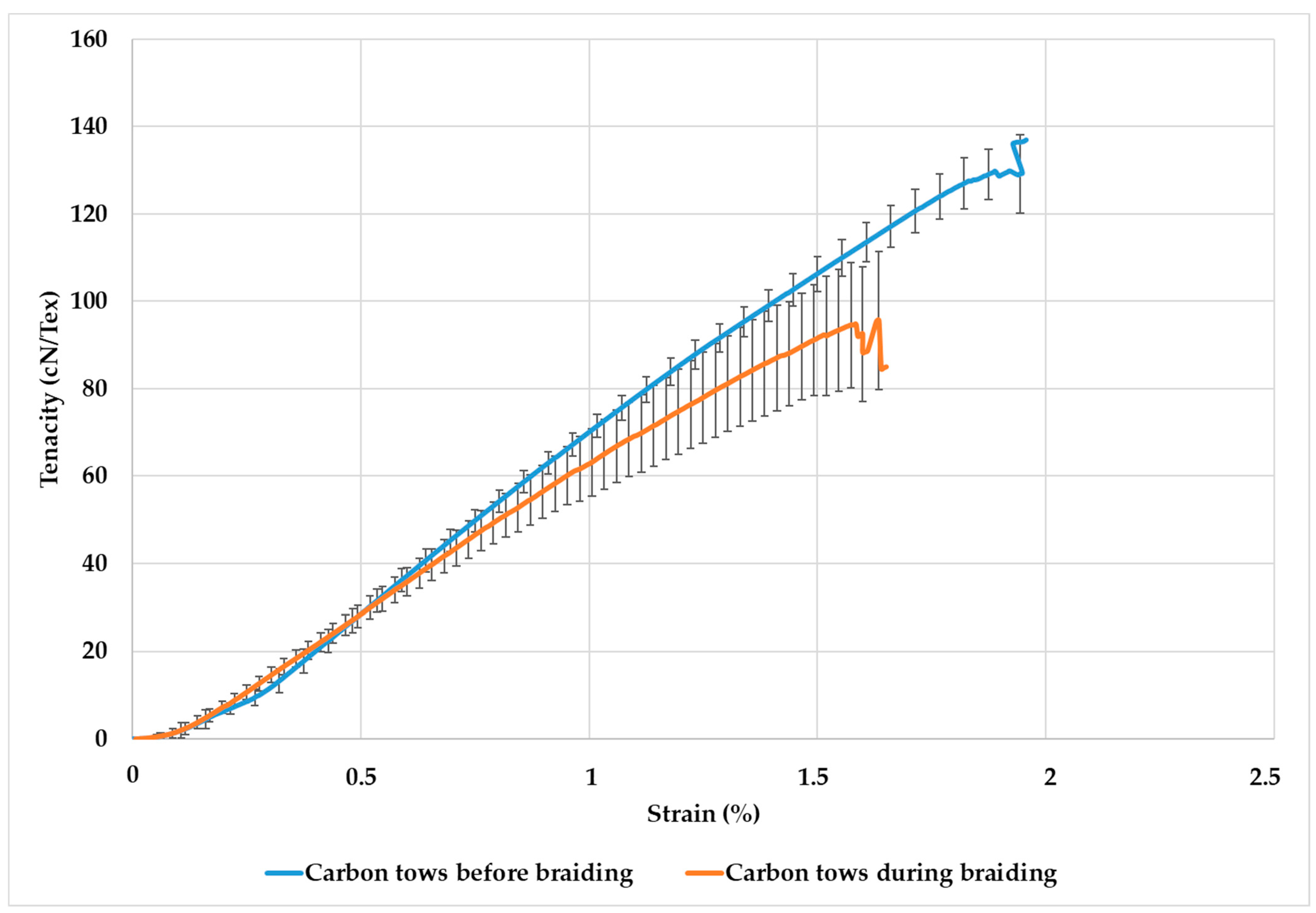
These visual observations were confirmed by the degradation of the carbon tows extracted from the sampling area (Figure 3), and quantified thanks to the criteria defined in the image analysis method detailed in Figure 4. The degradation criteria for carbon tows used in the production of both braids are given in Figure 9. These values showed 15% degradation when the stiffest springs were used (carbon tows of Braid 2), compared to 8% degradation with the less stiff springs (carbon tows of Braid 1). Results in Figure 9 show the same tendency observed in the rewinding step: a higher tension results in a higher degradation of the carbon tows. The values of the degradation criteria were quantitatively higher than those measured during the rewinding process (Figure 5). The influence of this degradation on the mechanical behavior of carbon tows was studied via the comparison of the tensile behavior of carbon tows extracted from the sampling area during the production of Braid 2 with that of the initial tows, as shown in Figure 10. Compared to the initial properties of the carbon tows before braiding, the degradation of carbon tows during the braiding stage affected their tensile properties. From these curves, parameters associated with these mechanical behaviors are compared in Table 5. This comparison shows a loss of properties equal to 17%, 30% and 27% for the strain at break, the load at break and the tenacity, respectively. These values are in accordance with the loss reported in several studies on the degradation of tows used in the winding process [19,20,21]. Compared to the influence of degradation on the mechanical behavior during the rewinding step (Figure 7b), these results show the significant influence of the level of damage during the braiding step.
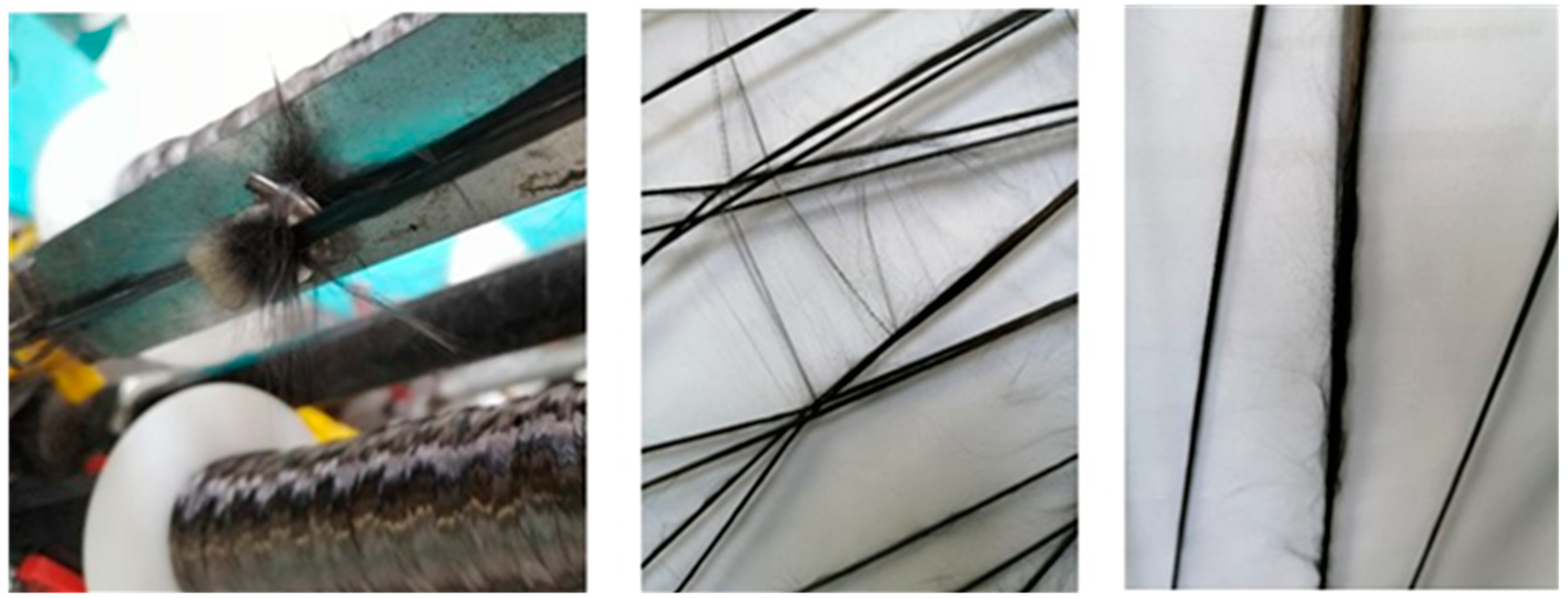
These results show that the degradation initialized during the rewinding of the tows increased during the braiding step. The braiding process produces much more friction between tows than the rewinding stage. The angles at which the tows must pass through the braider’s winding system are very high, and the tension control system pushes the tows, resulting in additional damage in the friction zones. As illustrated in Figure 11, the degradation of the tows is associated with different types of defects, such as fiber clusters that are stuck in the eyelets of the bobbins, broken filaments that interlace the tows together, and, in some cases, the break of tows during braiding. These defects lead to production stops and a lower quality of the braid obtained.
4. Conclusions
The degradation of 12 K carbon tows occurring during two specific stages associated with the braiding process was investigated in this experimental work. To produce a braid, the first step is rewinding the bobbins before placing them on the braiding machine. Carbon tows are brittle; it is therefore essential to understand the influence of the process parameters of each of these steps, rewinding and braiding, on their textile and mechanical properties. As detailed in this paper and following works published in the literature, the levels of degradation were analyzed and quantified thanks to an image analysis method applied on carbon tows extracted after the rewinding step and during the braiding stage. Results obtained in this study show that damage inside these tows starts at the rewinding step but this degradation has a low influence on their textile and mechanical properties, such as the linear density and tenacity. During this rewinding step, an experiment based on the values of three specific rewinding parameters exhibited the main influence of the tension generated by these parameters and applied on tows during this step on the level of degradation. During the braiding step, the influence of the tension of tows on their degradation has been studied considering the type of spring used in the bobbins in the braiding machine. Two springs with different stiffness values were used, and levels of degradation of carbon tows extracted from a sampling area before the braiding point were quantified. The friction between tows in this zone increased the damage inflicted on tows in this step more so than the rewinding step. Depending on the type of springs used, a loss of tenacity of up to 27% may be seen compared to the initial properties of these carbon tows before braiding. Different types of defects in tows generated during the braiding step have been identified. The objective of this study was the control and the optimization of the process parameters of these steps to minimize the degradation of the carbon tows. Future work will focus, using static approaches, on the influence of a larger range of values of parameters of these manufacturing steps on the damage quantified using the degradation criterion.
Author Contributions
Investigation: J.C.; writing—original draft preparation: J.C.; validation and supervision: D.S., X.L. and S.R.; writing—review and editing: D.S., X.L. and S.R. All authors have read and agreed to the published version of the manuscript.
Funding
This research received no external funding.
Data Availability Statement
Not applicable.
Conflicts of Interest
The authors declare no conflict of interest.
References
- Carey, J.P. Introduction to braided composites. In Handbook of Advances in Braided Composite Materials; Carey, J.P., Ed.; Woodhead Publishing: Sawston, UK, 2017; pp. 1–21. [Google Scholar] [CrossRef]
- Hao, W.; Huang, Z.; Zhang, L.; Zhao, G.; Luo, Y. Study on the torsion behavior of 3-D braided composite shafts. Compos. Struct. 2019, 229, 111384. [Google Scholar] [CrossRef]
- Ayranci, C.; Carey, J.P. 2D braided composites: A review for stiffness critical applications. Compos. Struct. 2008, 85, 43–58. [Google Scholar] [CrossRef]
- Kyosev, Y. Advances in Braiding Technology: Specialized Techniques and Applications. In Woodhead Publishing Series in Textiles; Woodhead Publishing: Oxford, UK, 2016; ISBN 978-0-08-100926-0. [Google Scholar]
- Emonts, C.; Grigat, N.; Merkord, F.; Vollbrecht, B.; Idrissi, A.; Sackmann, J.; Gries, T. Innovation in 3D Braiding Technology and Its Applications. Textiles 2021, 1, 185–205. [Google Scholar] [CrossRef]
- Melenka, G.W.; Carey, J.P. Experimental analysis of diamond and regular tubular braided composites using three-dimensional digital image correlation. J. Compos. Mater. 2017, 51, 3887–3907. [Google Scholar] [CrossRef]
- Potluri, P. Braiding. In Wiley Encyclopedia of Composites; Nicolais, L., Borzacchiello, A., Eds.; John Wiley & Sons, Inc.: Hoboken, NJ, USA, 2012. [Google Scholar] [CrossRef]
- Potluri, P.; Manan, A. Mechanics of non-orthogonally interlaced textile composites. Compos. Part A 2007, 38, 1216–1226. [Google Scholar] [CrossRef]
- Ayranci, A.; Carey, J.P. Predicting the longitudinal elastic modulus of braided tubular composites using a curved unit-cell geometry. Compos. Part B 2010, 41, 229–235. [Google Scholar] [CrossRef]
- Heieck, F.; Hermann, F.; Middendorf, P.; Schladitz, K. Influence of the cover factor of 2D biaxial and triaxial braided carbon composites on their in-plane mechanical properties. Compos. Struct. 2017, 163, 114–122. [Google Scholar] [CrossRef]
- Birkefeld, K.; Röder, M.; Von Reden, T.; Bulat, M.; Drechler, K. Characterization of Biaxial and Triaxial Braids: Fiber Architecture and Mechanical Properties. Appl. Compos. Mater. 2012, 19, 259–273. [Google Scholar] [CrossRef]
- Armanfard, A.; Melenka, G.W. Experimental evaluation of carbon fibre, fibreglass and aramid tubular braided composites under combined tension–torsion loading. Compos. Struct. 2021, 269, 114049. [Google Scholar] [CrossRef]
- Wu, Z.; Shi, L.; Cheng, X.; Xiang, Z.; Hu, X. Transverse impact behavior and residual axial compression characteristics of braided composite tubes: Experimental and numerical study. Int. J. Impact Eng. 2020, 142, 103578. [Google Scholar] [CrossRef]
- McGregor, C.; Vaziri, R.; Poursartip, A.; Xiao, X. Axial crushing of triaxially braided composite tubes at quasi-static and dynamic rates. Compos. Struct. 2016, 157, 197–206. [Google Scholar] [CrossRef]
- Czichos, R.; Bareiro, O.; Pickett, A.K.; Middendorf, P.; Gries, T. Experimental and numerical studies of process variabilities in biaxial carbon fiber braids. Int. J. Mater. Form. 2021, 14, 39–54. [Google Scholar] [CrossRef]
- Wang, C.; Tang, M.; Liu, W.; Zhu, T. Study on Microstructure Characteristics of Axially Braided Carbon/Carbon Composites Based on SEM and Micro-CT. Materials 2020, 13, 1414. [Google Scholar] [CrossRef] [PubMed] [Green Version]
- Chai, Y.; Wang, Y.; Yousaf, Z.; Storm, M.; Vo, N.T.; Wanelik, K.; Burnett, T.L.; Potluri, P.; Withers, P.J. Following the effect of braid architecture on performance and damage of carbon fibre/epoxy composite tubes during torsional straining. Compos. Sci. Technol. 2020, 200, 108451. [Google Scholar] [CrossRef]
- Archer, E.; Buchanan, S.; Mcllhagger, A.T.; Quinn, J.P. The effect of 3D weaving and consolidation on carbon fiber tows, fabrics and composites. J. Reinf. Plast. Compos. 2010, 29, 3162–3170. [Google Scholar] [CrossRef]
- Lee, B.; Leong, K.H.; Herszberg, I. Effect of weaving on the tensile properties of carbon fibre tows and woven composites. J. Reinf. Plast. Compos. 2001, 20, 652–670. [Google Scholar] [CrossRef]
- Rudov-Clark, S.; Mouritz, A.P.; Lee, L.; Bannister, M.K. Fibre damage in the manufacture of advanced three-dimensional woven composites. Compos. Part A 2003, 34, 963–970. [Google Scholar] [CrossRef]
- Abtew, M.A.; Boussu, F.; Bruniaux, P.; Loghin, C.; Cristian, I.; Chen, Y.; Wang, L. Yarn degradation during weaving process and its effect on the mechanical behaviours of 3D warp interlock p-aramid fabric for industrial applications. J. Ind. Text. 2022, 51 (Suppl. S5), 9047S–9070S. [Google Scholar] [CrossRef]
- Ebel, C.; Mierzwa, A.; Kind, K. Yarn damage during braiding of reinforcement fibers for composites. In Chapter 13 of Advances in Braiding Technology; Woodhead Publishing Series in Textiles; Woodhead Publishing: Oxford, UK, 2016. [Google Scholar] [CrossRef]
- Kyosev, Y. Yarn winding operations in braiding. In Chap.10 of Braiding Technology for Textiles; Kyosev, Y., Ed.; Woodhead Publishing Series in Textiles; Woodhead Publishing: Oxford, UK, 2015. [Google Scholar]
- Roy, S.S.; Zao, W.; Potluri, P. Influence of Braid Carrier Tension on Carbon Fibre Braided Preforms. In Recent Developments in Braiding and Narrow Weaving; Kiosev, Y., Ed.; Springer International Publishing Switzerland: Berlin/Heidelberg, Germany, 2016. [Google Scholar] [CrossRef]
- NF EN ISO 5084; Textiles-Determination of Thickness of Textiles and Textile Products. AFNOR: Saint-Denis, France, 1996.
- NF G07-316; Textiles-Tests of Yarns-Determination of Linear Density. AFNOR: Saint-Denis, France, 1988.
- NF EN ISO 2062; Textiles–Yarns from Packages–Determination of Single-End Breaking Force and Elongation at Break Using Constant Rate of Extension (CRE) Tester. AFNOR: Saint-Denis, France, 2010.
- Ratera® Winding Machines. Available online: https://ratera.com/en/applications/auxiliary-machines/ (accessed on 22 November 2022).
- Cherif, C. Textile Werkstoffe für den Leichtbau; Springer: Berlin/Heidelberg, Germany, 2011. [Google Scholar] [CrossRef]
- Ebel, C.; Brand, M.; Drechsler, K. Effects of fiber damage on the efficiency of the braiding process. In Proceedings of the Composites Week in Leuven and TexComp-11 Conference, Leuven, Belgium, 16–20 September 2013. [Google Scholar] [CrossRef]
- Duchamp, B.; Soulat, D.; Legrand, X. The tensile behaviour of biaxial and triaxial braided fabrics. J. Ind. Text. 2018, 47, 2184–2204. [Google Scholar] [CrossRef]
- Jacquot, P.B.; Wang, P.; Soulat, D.; Legrand, X. Analysis of the preforming behaviour of the braided and woven flax/polyamide fabrics. J. Ind. Text. 2016, 46, 698–718. [Google Scholar] [CrossRef]
- Xiao, S.; Wang, P.; Soulat, D.; Gao, H. An exploration of the deformability behaviour dominated by braiding angle during the forming of the triaxial carbon fibre braids. Compos. Part A 2020, 133, 1058990. [Google Scholar] [CrossRef]
- Zhai, W.; Soulat, D.; Legrand, X.; Wang, P. Influence of the Unit Cell Parameters on the Thermomechanical Non-Symmetric In-Plane Shear Behavior of 2D Biaxial Braided Preform for Thermoplastic Biocomposites. Polymers 2022, 14, 1117. [Google Scholar] [CrossRef] [PubMed]
- Tourlonias, M.; Bueno, M.A.; Fassi, G.; Aktas, I.; Wielhorski, Y. Influence of friction angle between carbon single fibres and tows: Experimental analysis and analytical model. Compos. Part A 2019, 124, 105478. [Google Scholar] [CrossRef]
- Smerdova, O.; Benchekroun, O.; Brunetiere, N. Transversal friction of epoxy-lubricated and dry carbon tows: From initial stages to stabilised state. Compos. Part A 2021, 143, 1062363. [Google Scholar] [CrossRef]
- Wu, N.; Xie, X.; Wang, J.; Feng, Y.; Jiao, Y.; Chen, L.; Xu, J.; Jian, X. Effect of normal load on the frictional and wear behaviour of carbon fiber in tow-on-tool contact during three-dimensional weaving process. J. Ind. Text. 2022, 51 (Suppl. S2), 2753S–2773S. [Google Scholar] [CrossRef]
- Image J: An Open Platform for Scientific Image Analysis. Available online: http://imagej.net/Welcome (accessed on 1 July 2022).
Figure 1.
Scheme of the winding machine with configurations of the bobbin orientation.

Figure 2.
Positions of the delivering bobbin: (a) high position (32°), (b) low position (20°).

Figure 3.
Braiding machine (left) and sampling area (right).

Figure 4.
Image analysis of damage and definition of degradation criteria.

Figure 5.
Evolution of degradation criteria as a function of rewinding parameters.

Figure 6.
(a) Tension during rewinding process; (b) pictures of carbon tows after rewinding.

Figure 7.
(a) Linear density of samples before and after rewinding; (b) tensile characteristics of samples before and after rewinding.
Figure 7.
(a) Linear density of samples before and after rewinding; (b) tensile characteristics of samples before and after rewinding.

Figure 8.
Braid production: (a) braid appearance; (b) carbon tows in sampling area.

Figure 9.
Degradation of carbon tows during the braiding step.

Figure 10.
Tensile behavior of carbon tows before and during braiding with the stiffest springs.

Figure 11.
Different types of defects that can occur during braiding process.


Table 1.
Properties of 12 K carbon tows.
| Thickness (mm) | 2.5 ± 0.04 |
| Linear density (Tex) | 452.68 ± 1.25 |
| Tenacity (cN/Tex) | 136.9 ± 5.9 |
| Strain at break (%) | 1.96± 0.04 |
Table 2.
Design of rewinding experiment.
| Parameters | Level 1 | Level 2 |
|---|---|---|
| Orientation of the bobbin | Perpendicular | Parallel |
| Rewinding speed | Low | High |
| Position of the delivering bobbin | 32° | 20° |
Table 3.
Braiding parameters and properties of carbon braids.
| Parameters | Braid 1 | Braid 2 |
|---|---|---|
| Tension of springs used (cN) | 115 | 200 |
| Number of tows | 96 | 96 |
| Type of braids | biaxial | biaxial |
| Braiding angle (°) | 45 | 45 |
| Carrier rotational speed (tr/min) | 90 | 90 |
| Production speed (m/h) | 30 | 30 |
Table 4.
Elementary tests to validate the method.
| Sample Name | Pictures of Samples | Degradation |
|---|---|---|
| Initial tows |  | 1.4% |
| 32–High–Parallel |  | 4.7% |
| 32–High–Perpendicular |  | 7.6% |
| 32–Low–Perpendicular |  | 10.1% |
Table 5.
Tensile characteristics of carbon tows before and during braiding with the stiffest springs.
Table 5.
Tensile characteristics of carbon tows before and during braiding with the stiffest springs.
| Parameters | Before Braiding | During Braiding |
|---|---|---|
| Strain at break (%) | 1.93 ± 0.04 | 1.61 ± 0.03 |
| Load at break (N) | 584.74 ± 26.51 | 409.08 ± 62.42 |
| Tenacity at break (cN/Tex) | 131.40 ± 5.96 | 96.03 ± 14.65 |
Disclaimer/Publisher’s Note: The statements, opinions and data contained in all publications are solely those of the individual author(s) and contributor(s) and not of MDPI and/or the editor(s). MDPI and/or the editor(s) disclaim responsibility for any injury to people or property resulting from any ideas, methods, instructions or products referred to in the content. |
© 2023 by the authors. Licensee MDPI, Basel, Switzerland. This article is an open access article distributed under the terms and conditions of the Creative Commons Attribution (CC BY) license (https://creativecommons.org/licenses/by/4.0/).
Share and Cite
MDPI and ACS Style
Calba, J.; Soulat, D.; Legrand, X.; Renauld, S. Damage Investigation on the Carbon Tows during Rewinding and Braiding Processes. Fibers 2023, 11, 30. https://doi.org/10.3390/fib11030030
AMA Style
Calba J, Soulat D, Legrand X, Renauld S. Damage Investigation on the Carbon Tows during Rewinding and Braiding Processes. Fibers. 2023; 11(3):30. https://doi.org/10.3390/fib11030030
Chicago/Turabian StyleCalba, Justine, Damien Soulat, Xavier Legrand, and Sébastien Renauld. 2023. "Damage Investigation on the Carbon Tows during Rewinding and Braiding Processes" Fibers 11, no. 3: 30. https://doi.org/10.3390/fib11030030
Note that from the first issue of 2016, this journal uses article numbers instead of page numbers. See further details here.