Article

Six-Core GeO2-Doped Silica Microstructured Optical Fiber with Induced Chirality

by
Anton V. Bourdine
1,2,3,4,
Vladimir V. Demidov
2,
Konstantin V. Dukelskii
2,4,5,
Alexander V. Khokhlov
2,
Egishe V. Ter-Nersesyants
2,
Sergei V. Bureev
2,
Alexandra S. Matrosova
2,5,
Grigori A. Pchelkin
2,4,6,
Artem A. Kuznetsov
7,
Oleg G. Morozov
7,*,
Ilnur I. Nureev
7,
Airat Zh. Sakhabutdinov
7,
Timur A. Agliullin
7,
Michael V. Dashkov
1,
Alexander S. Evtushenko
1,
Elena S. Zaitseva
1,
Alexander A. Vasilets
8,
Azat R. Gizatulin
9,
Ivan K. Meshkov
9,
Yaseera Ismail
10,
Francesco Petruccione
11,12,
Ghanshyam Singh
13,
Manish Tiwari
14 and
Juan Yin
15
add Show full author list remove Hide full author list
1
Department of Communication Lines, Povolzhskiy State University of Telecommunications and Informatics, 23, Lev Tolstoy Street, Samara 443010, Russia
2
JSC “Scientific Production Association State Optical Institute Named after Vavilov S.I.”, 36/1, Babushkin Street, St. Petersburg 192171, Russia
3
“OptoFiber Lab” LLC, Skolkovo Innovation Center, 7, Nobel Street, Skolkovo Innovation Center, Moscow 143026, Russia
4
Department of Photonics and Communication Links, Saint Petersburg State University of Telecommunications Named after M.A. Bonch-Bruevich, 22, Bolshevikov Avenue, St. Petersburg 193232, Russia
5
Faculty of Photonics and Optical Information, School of Photonics, ITMO University, Bldg. A, 49, Kronverksky Alley, St. Petersburg 197101, Russia
6
Institute of Physics, Nanotechnology and Telecommunications, Peter the Great St. Petersburg Polytechnic University, Bldg. II, 29, Politekhnicheskaya Str., St. Petersburg 194064, Russia
7
Department of Radiophotonics and Microwave Technologies, Kazan National Research Technical University Named after A.N. Tupolev-KAI, 10, Karl Marx Street, Kazan 420111, Rep. Tatarstan, Russia
8
Department of Physics and Mathematics Branches of Science and Information Technologies, Volga Region State University of Physical Culture, Sport and Tourism, 35, Universiade Village, Kazan 420010, Rep. Tatarstan, Russia
9
Department of Telecommunication Systems, Ufa University of Science and Technology, 12, Karl Marx Street, Ufa 450000, Russia
10
Quantum Research Group, School of Chemistry and Physics, University of KwaZulu-Natal, Durban 4001, South Africa
11
School of Data Science and Computational Thinking, Stellenbosch University, Stellenbosch 7602, South Africa
12
National Institute for Theoretical and Computational Sciences (NITheCS), Durban 4001, South Africa
13
Department of Electronics and Communication Engineering, School of Electrical and Electronics & Communication Engineering, Malaviya National Institute of Technology, J.L.N Road, Jaipur 302017, Rajasthan, India
14
School of Electrical and Electronics & Communication Engineering, Manipal University Jaipur, Dehmi Kalan, Off Jaipur-Ajmer Expressway, Jaipur 303007, Rajasthan, India
15
Division of Quantum Physics and Quantum Information, University of Science and Technology of China, No.99 Xiupu Road, Pudong District, Shanghai 200093, China
*
Author to whom correspondence should be addressed.
Fibers 2023, 11(3), 28; https://doi.org/10.3390/fib11030028
Submission received: 3 December 2022 / Revised: 16 February 2023 / Accepted: 6 March 2023 / Published: 7 March 2023
(This article belongs to the Special Issue Optical Fibers as a Key Element of Distributed Sensor Systems II)

Abstract

:
This work presents a fabricated silica few-mode microstructured optical fiber (MOF) with a special six GeO2-doped core geometry, an outer diameter of 125 µm (that corresponds to conventional commercially available telecommunication optical fibers), and improved induced twisting up to 500 revolutions per 1 m (under a rotation speed of 1000 revolutions per meter with a drawing speed of ~2 m per minute). The article discusses some technological aspects and issues of manufacturing the above-described twisted MOFs with complicated structures and geometry as GeO2-doped silica supporting elements for them. We present results of some measurements performed for fabricated samples of chiral silica six-GeO2-doped-core few-mode MOFs with various orders of twisting and both step and graded refractive indexes of “cores”. These tests contain research on MOF geometrical parameters, attenuation, and measurements of the far-field laser beam profile.

1. Introduction

To the best of our knowledge, twisted optical fibers have been known for about forty years; for example, the idea of manufacturing a fiber with the rotation of a preform was first presented in [1], and the authors of [2] propose twisting of an already drawn fiber, rather than a preform. It is known that fiber twist can reduce polarization mode dispersion (PMD) in single-mode fibers, as shown in [1,2,3,4], and, in the case of multimode optical fibers, induced chirality (including twist) contributes to the differential mode delay (DMD), which decreases as the transmission bandwidth increases [5,6]. Twisted optical fibers with a high degree of twisting have great potential for applications in high-power fiber laser systems, such as high-order mode-suppression active fibers [7] or highly mode-locked optical fibers for clad-pumped devices [8].
Recently, twisted microstructured optical fibers (MOFs) have been considered to have great potential for various applications in both fiber optic sensor networks and telecommunication systems [9]. The same method of inducing chirality after stretching the MOF, first demonstrated in 2004 in [10], made it possible to significantly reduce the PMD. To date, a number of theoretical and experimental works have been published showing that twisted MOFs maintain polarization and generate optical activity [11,12,13,14,15] and are also considered as fiber optic probes for measuring strain and twisting [16,17,18] and sensors for measuring magnetic field and electric current [19]; they are also used as spectral and mode filters [20], optical tweezers, and are used in optical orbital angular momentum (OAM) based telecommunication technologies [21,22,23,24,25,26,27,28,29,30,31].
This paper presents first-time successfully fabricated silica twisted few-mode multicore MOFs. These MOFs differ by GeO2-doped special core geometry, contain six cores (six-core MOF), have an outer diameter of 125 µm, and operate in a few-mode regime. MOFs are twisted with a step of 1000 revolutions per minute (e.g., at a drawing speed of the order of two meters per minute at ~500 revolutions per meter (rpm)).
The rest of this paper is structured as follows. Section 2 is focused on technological issues of strongly twisted silica MOF manufacturing and describes in detail the performed required modifications of optical fiber drawing tower equipment. Section 3.1 introduces a technique for the fabrication of silica GeO2-doped MOF supporting element preforms (rod blanks). Section 3.2 is concerned with the analysis of GeO2-doped six-core-MOF to localize the GeO2 dopant concentration, which would provide desired four-mode operation at a wavelength of λ = 1550 nm. Section 3.3 and 3.4 present successfully fabricated silica few-mode GeO2-doped six-core-MOFs with graded- and step-index refractive index profiles and twistings of 50…500 rpm. They contain results of manufactured MOF geometry and transmission spectra measurements, while Section 3.5 is focused on measurements of beam profiles under various launching conditions and laser sources. Section 4 presents our conclusions.

2. Fabrication of Twisted Silica Microstructured Optical Fibers

We described in detail the first attempts of weakly twisted silica MOF fabrication in previously published works [32,33,34,35,36]. Here, the same approach proposed in [1] was utilized: rotation of optical fiber preform during the drawing process. Some modifications to the drawing tower were performed: we installed a stepper motor to the feed unit to add the rotation option to the drawing system. The maximal rotation speed of the stepper motor was only 200 revolutions per minute, which provides a maximum chirality of 100 rpm under the drawing speed of 2 m per minute (Figure 1a). Additionally, we developed and fabricated a special fluoroplastic rotational adapter (Figure 1b) that directly connects an excess pressure hose to the top end of the cane and fixes it without twisting. This adapter provides the ability of cane rotation during the MOF drawing under the desired speed, and blocks drops in pressure between the hose and the top end of the cane due to the sealed internal space of the rotational adapter.
Therefore, manufacturing of twisted MOFs contains three steps: (1) MOF stack (preform) formation, (2) cane (pre-fiber) fabrication by re-drawing, and (3) drawing of MOF from the cane with twisting [32,33,34,35,36].
During the first step, we re-drew high-purity fused synthetic silica supporting elements (rods and tubes with a content of hydroxyl groups less than 1 ppm) to micro-rods and capillaries with an outer diameter of 1.37 mm and cut them into segments with lengths 30 cm long. After a series of operations for the preparation of both capillaries and micro-rods (end melting in the flame of an oxyhydrogen torch under blowing by dried oxygen, chemical cleaning by concentrated hydrofluoric acid, washing by distilled water, drying in a muffle furnace, etc.), we formed an MOF stack by manually placing these prepared elements inside an 18 mm inner diameter silica substrate tube, according to the desired cross-section geometry/structure, and melted its end by using MCVD station.
During the second step, by using a drawing tower, we drew MOF cane with a length of 0.5 m and an outer diameter of 3 mm from the prepared stack under vacuum at 0.5 atm, with a feeding speed of 10 mm per minute, a drawing speed of 0.5 m per minute, and a drawing temperature of 1920 °C [32,33,34,35,36].
The third step contained the installation of prepared MOF cane into the feed unit of the drawing tower. Then it is driven into the high-temperature furnace and re-drawn to optical fiber under twisting provided by the installed stepper motor. We tested various combinations of excess pressure, drawing temperature, drawing speed, and rotation speed [32,33,34,35,36] to obtain twisted MOFs with desired non-perturbed geometry/microstructure over the drawn length. After a series of experiments, the first pilot samples of twisted MOFs with a desired pitch ratio of 0.95 were successfully fabricated under excess pressure of 25 mbar and a drawing temperature of 1900 °C [32,33,34,35,36]. As a result, the performed modifications to the drawing tower [32,33,34,35,36] provided fabrication of MOFs with weakly induced chirality from 10 rpm twisting (rotation speed is 20 revolutions per minute with MOF drawing speed of 2 m per minute) up to 66 rpm twisting (rotation speed is 200 rpm with MOF drawing speed 3 m per minute).
Therefore, the next aim was to obtain a strong improvement in the fabricating silica MOF twisting order by decreasing the drawing speed with the tower feed unit or by increasing the preform rotation speed in the tower feed unit. The first approach was implemented during the fabrication of silica few-mode MOF with typical hexagonal geometry with offset core (ratio of air hole diameter to the pitch ratio is 0.65…0.70, quality of spatial guided modes is 3…4). Here, the chirality order was improved up to 217 rpm. Pilot samples of the above-described MOF were fabricated under a slow drawing speed of 0.9 m per minute. However, further drawing speed decreases led to the intermittent interruption of the drawing process due to an unacceptably low pull force and, thereby, to the optical fiber outer diameter local deviations from the desired reference value under failures of MOF cross-section geometry parameters. Because the maximal value of stepper motor rotation speed is 200 revolutions per minute, the maximal twisting order for proposed chiral MOFs, fabricated by the described technique, was limited only by 217 rpm.
During the next step, we performed a further series of drawing tower equipment modifications, focused on a strong improvement in the feed unit rotation speed. Analogous to the previously proposed solution [32,33,34,35,36], here, we also implemented a complete replacement of the stepper motor (Figure 1c) with a commutator motor with a driver and control system:
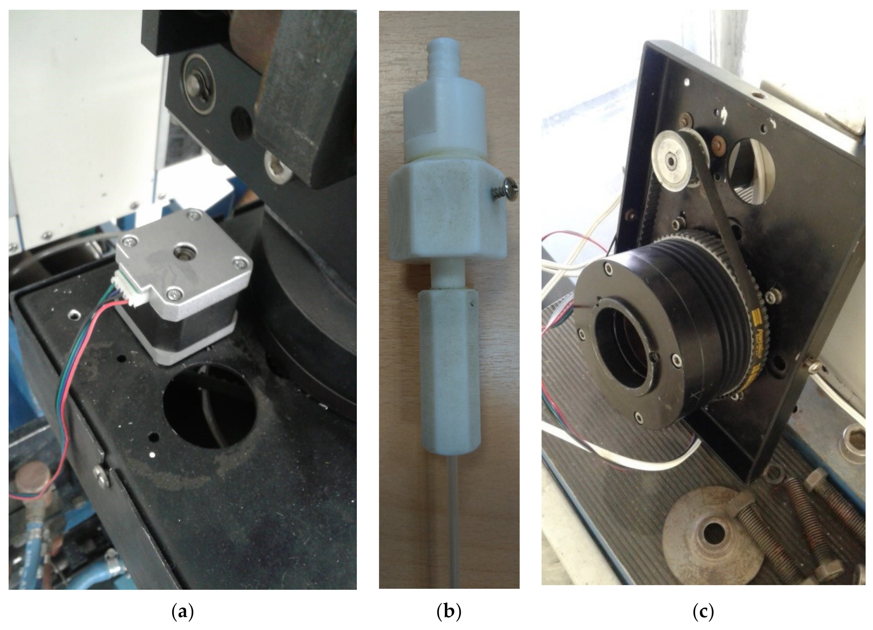
  • By corresponding engineering research carried out, we developed technical specifications for a new rotation unit and replaced the step engine with a commutator motor, providing a maximal rotation speed of 2000 revolutions per minute.
  • A lightweight aluminum carrier for the commutator motor was designed and fabricated.
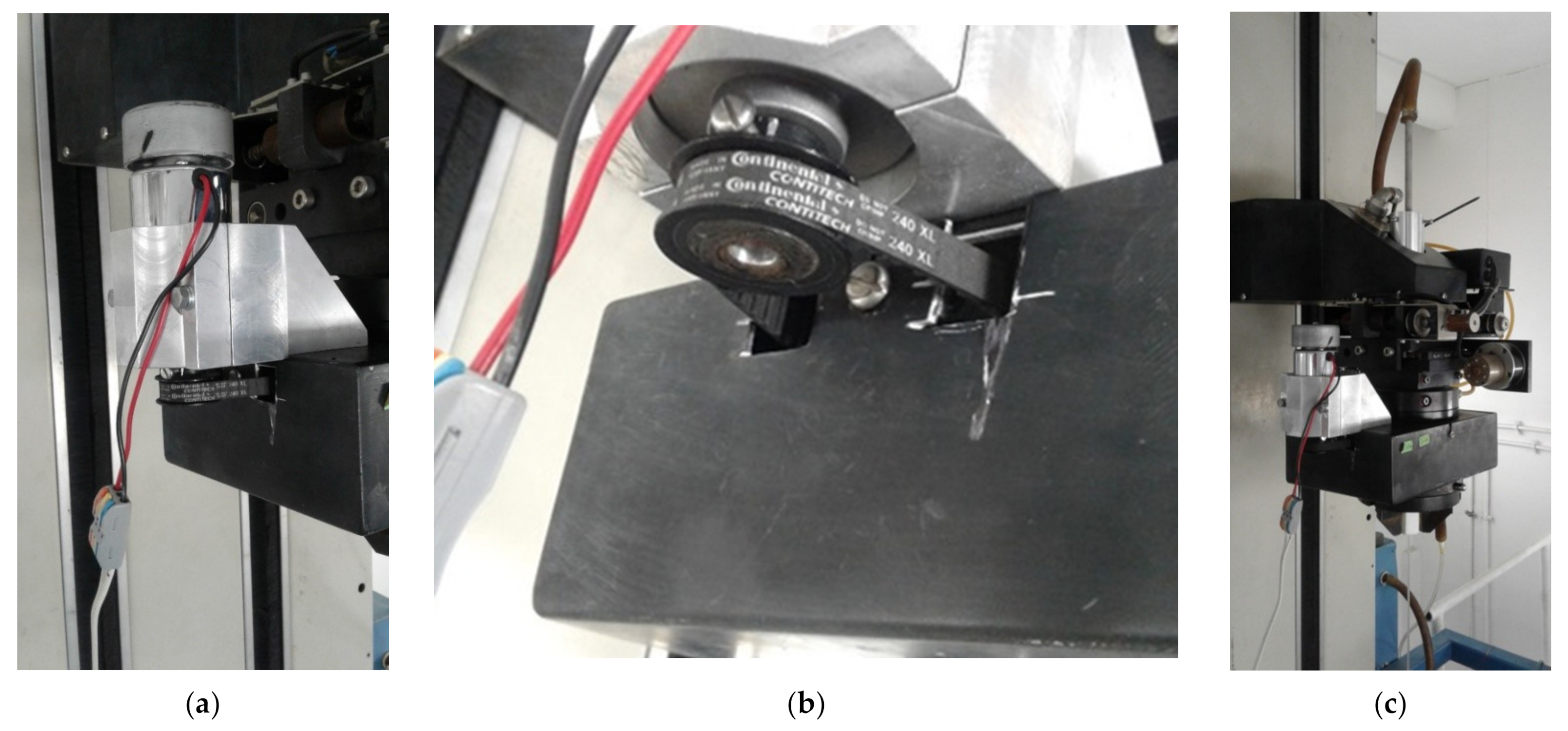
  • The commutator motor was installed and fixed on the feed unit chuck by the fabricated carrier (Figure 2a).
  • We utilized/installed a new drive belt with an improved length due to increasing the distance between the commutator motor shaft and feed unit chuck (Figure 2b).
  • A supporting pad was mounted with the fixed commutator motor, protective shroud, and driving system in the drawing tower feed unit (Figure 2c).
  • We modified the existing electronic control unit with a power supply and driver for commutator motor control: here, the engage switch and the quantity controller of revolutions were connected to the outside control panel.
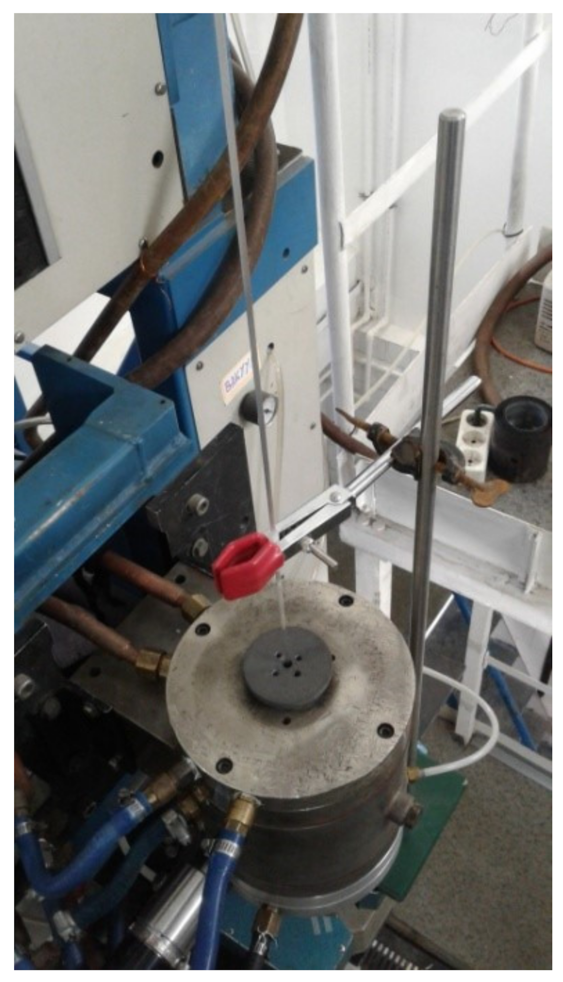
  • We proposed and fabricated a special device for additional fixing of MOF cane to prevent its unacceptably strong vibrations in the horizontal plane with further destruction, occurring under a rotation speed of more than 300 revolutions per minute. This fixing device contains a ring stand with a clamped piece of fluoroplastic tube with a corresponding diameter. It was mounted between the tower feed unit and the tower furnace (Figure 3).
  • As a result, the performed modifications provide improvements in the preform rotation speed in the drawing tower feed unit of up to 2000 revolutions per minute and in the chirality of fabricating twisted optical fibers of up to 1000 rpm under a drawing speed of 2 m per minute for silica graded-index few-mode optical fiber with typical “telecommunication” structure (solid core, bounded by one outer solid cladding) and up to 500 rpm under the same drawing speed for MOFs.

3. Results of Twisted Silica Microstructured Optical Fibers with Special Six GeO2-Doped Core Geometry Characterization

3.1. Technological Issues

Earlier on [32,33], we fabricated pilot samples of chiral few-mode MOFs with induced twisting at 10 and 66 rpm, based on the only silica supporting elements (both rods and tubes). Here we focused on the forming of desired special MOF cross-section geometry that provides cut-off conditions only for 3…4 guided modes under weak twisting. According to published works [9,21,22,23,24,25,26,27,28,29,30,31], twisted MOFs are promoted as generators/guided systems for OAM modes or optical vortices. In papers [32,33], we confirmed the ability of implementation of few-mode MOFs with induced longitudinal twisting and demonstrated that improvement in the chirality order for the same MOF leads to a general radial mode field localization near the core center under a more uniform averaging of the emission intensity between excited guided modes. For example, two-mode MOF with hexagonal cross-section structure and offset core (pitch ratio 0.55) under chirality improvement from 10 to 66 rpm transforms typical superimposed bipartite radial mode field distribution to quasi-ring pattern [36].
This work is focused on the attempt to provide a complimentary degree of freedom—spatial variation in the refractive index over the few-mode MOF cross-section near the optical fiber center. Here, during stack forming, we utilized silica supporting elements (rods) with an improved refractive index by GeO2 dopants. The proposed design structure was a six-core-MOF with GeO2-doped silica “cores” equidistant from the MOF center on the double-pitch distance. We tested both graded-index (bought from a third-party manufacturer—these rods were fabricated from high-purity fused silica glass with a specified OH content below 1 ppm (analog of the brand Heraus Suprasil F300 or OHARA SK-1310)) and step-index rods (fabricated by own research team via conventional MCVD technique). For step-index rods, we utilized silica supporting tubes with a high OH-group concentration (more than 1000 ppm—analog to the brands Heraeus Suprasil Standard, Saint-Gobain Spectrosil A and B, Corning HPFS 7980, JGS1, Dynasil 1100/Dynasil 4100, Russian GOST 15130-86 “Optical quartz glass” KU-01, etc.), because the MCVD-process should be performed under low temperatures to prevent tube deformation and redundant evaporation of highly GeO2-doped quartz near-surface layers. The same low-price silica glass elements (rods and tubes) were also applied for the main part of the designed MOF, based on stacks with capillaries and micro-rods.
Here, the technological process of fabrication of GeO2-doped silica rod blanks contained the following sequential steps:
  • Distilled water flushing of the silica supporting tube and, further, its drying under normal conditions.
  • Installation of supporting tube in the chucks of MCVD station.
  • Supplying SF6 to the inside of the tube for chemical etching of distorted near-surface quartz layers.
  • Deposition of phosphor-silicate quartz layers to prevent the diffusion of OH-groups from the supporting tube to the germane-silicate quartz layers.
  • Deposition of germane-silicate quartz layers for an improvement in refractive index and material photosensitivity by the formation of germanium oxygen-deficient centers.
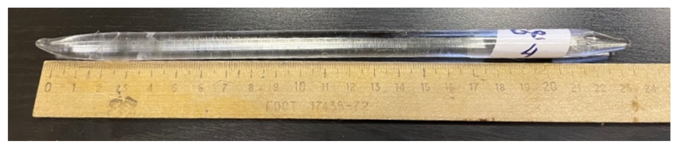
  • Finalization of rod blank fabrication by high-temperature collapsing of supporting tube with deposited layers of doped quartz.
Measured by the refractometer Photon Kinetics P-101, refractive index profiles of rod blanks, been fabricated as the supporting elements for “cores”, are represented in Figure 4: purchased graded-index rod blank (Figure 4a) and fabricated quasi-step-index rod blank (Figure 4b).
Geometrical and optical parameters of both graded-index and quasi-step-index rod blanks are presented in Table 1.
The design of the fabricated six-core-MOF is presented in Figure 5. It is supposed that such geometry, combined with induced chirality, would improve modal stability and would concentrate (e.g., focus) mode fields closely to “GeO2-centres”. We prepared the fiber stack (Figure 5a–c), then redrew it into the cane with an outer diameter of 2.92 mm (Figure 5d).
After that, two types of six-core-MOF samples with the core capillaries drawn from the preform with the customized graded-index profile and a core/cladding diameter ratio of 0.8 (Figure 5e) and the preform with the step-index profile and a core/cladding diameter ratio of 0.4 (Figure 5f) were fabricated. The geometry of the fabricated six-core-MOFs was scaled to an outer diameter of 125 µm, which is a typical cladding diameter for conventional telecommunication optical fibers of ratified ITU-T Recommendations and ISO/IEC/TIA/ANSI standards, to simplify connection to commercially available measurement/test equipment systems and utilization of field mounting tools such as strippers, precision cleavers, fusion splicers, etc.
The core preform rod blank was fabricated by the above-described technological route with an additional final procedure of pure quartz layer deposition. Therefore, four layers of phosphor-silicate quartz, fifty-five layers of germane-silicate quartz, and five layers of pure silica quartz were deposited over the inner surface of the supporting silica tube. The resulting thickness of the deposited germane-silicate quartz layers was approximately 4.55 mm.
During the high-temperature process of collapsing the tube to a rod, an oxyhydrogen torch was moved with a speed of 5 mm/min under a flame temperature of 1820 °C for the first pass, 5 mm/min under 1800 °C for the second pass, and 3 mm/min under 1800 °C for the third pass. Therefore, the usable length of the core preform was 130 mm for an outer diameter of 11.22 mm (Figure 6).
Figure 4. Refractive index profiles of GeO2-doped silica rod blanks: (a) purchased graded-index rod blank; (b) fabricated quasi-step-index rod blank.
Fibers 11 00028 g004
Figure 5. Six-core-MOF: (a) stack; (b) stack inside a silica tube; (c) MOF preform; (d) MOF cane; (e) MOF cane cross-section; (f) MOF cross-section.
Fibers 11 00028 g005
Figure 6. Fabricated core preform for MOF core supporting elements.
Fibers 11 00028 g006
Therefore, based on the conventional MCVD technique for special silica optical fiber preform manufacturing, we developed technological methods for the fabrication of silica with a highly concentrated GeO2-dopant inside the layers of rod blank preforms. The above-described rod blanks may be utilized as supporting elements for silica MOF canes/preforms. We assume that in addition to induced chirality (twisting during MOF drawing), the inclusion of MOF structure silica GeO2-doped supporting elements will provide contraction (e.g., focusing) of the radial mode field distribution to core centers and provide new properties, also improved by optionally recording fiber Bragg gratings.

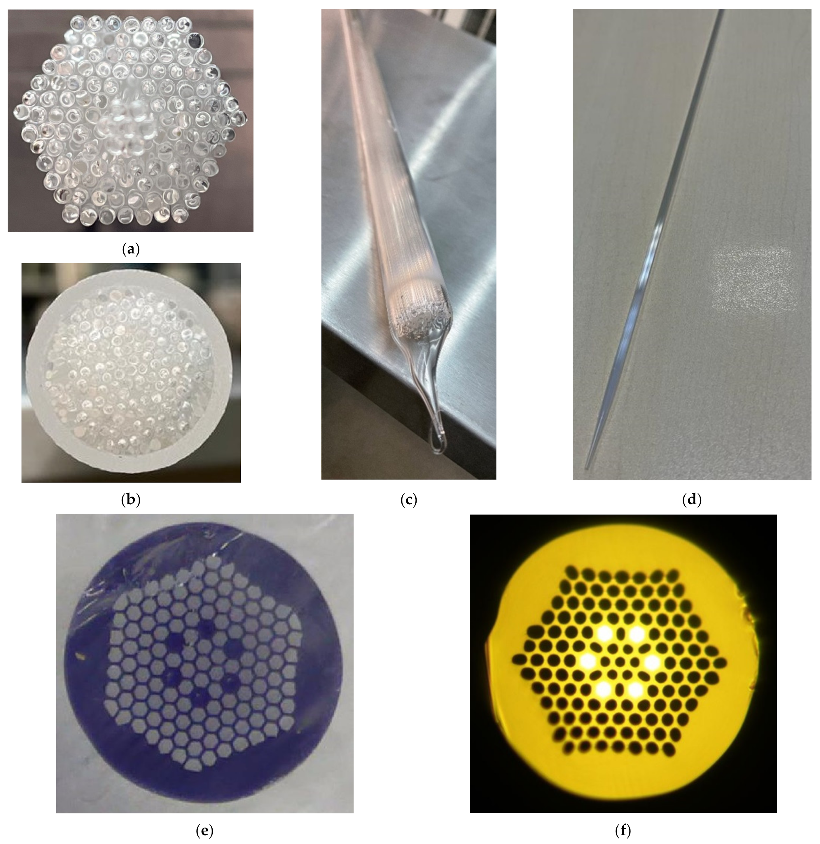
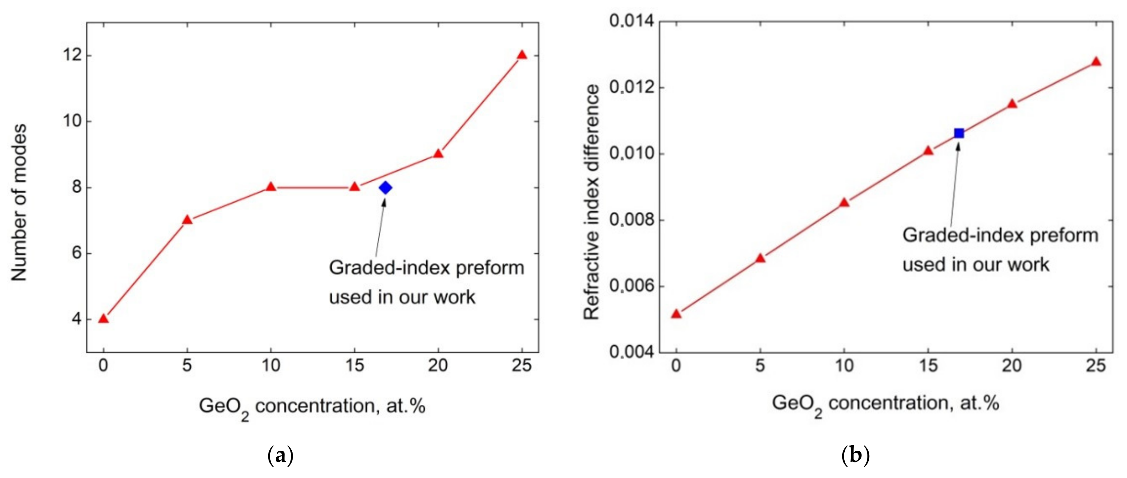
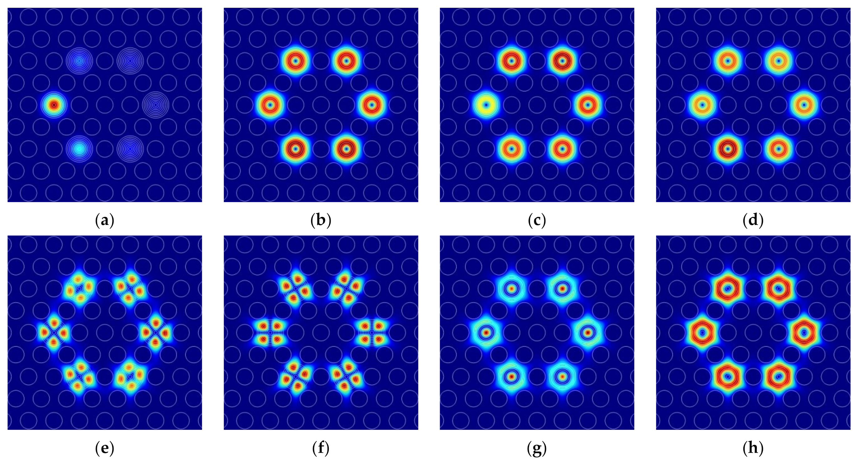
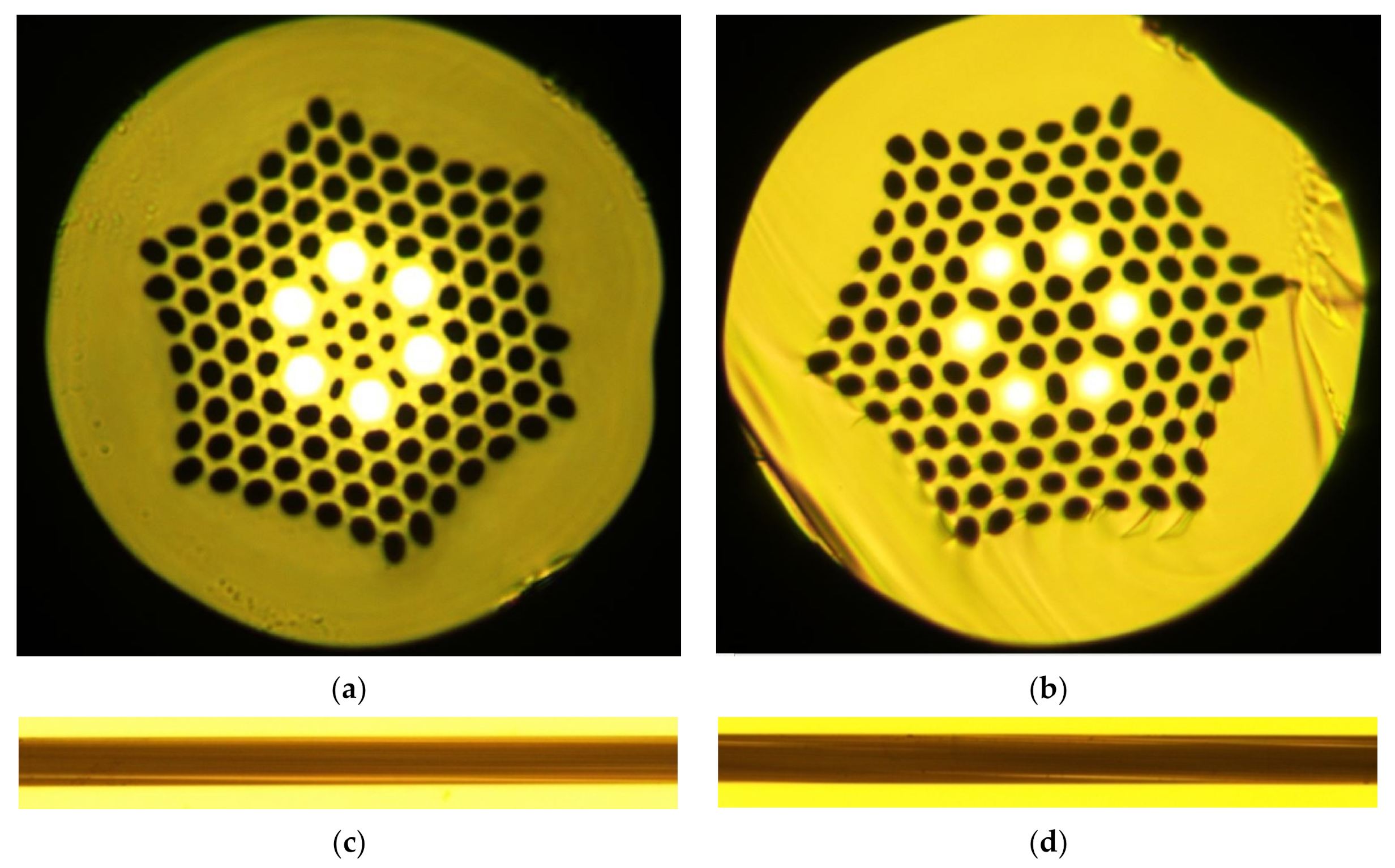
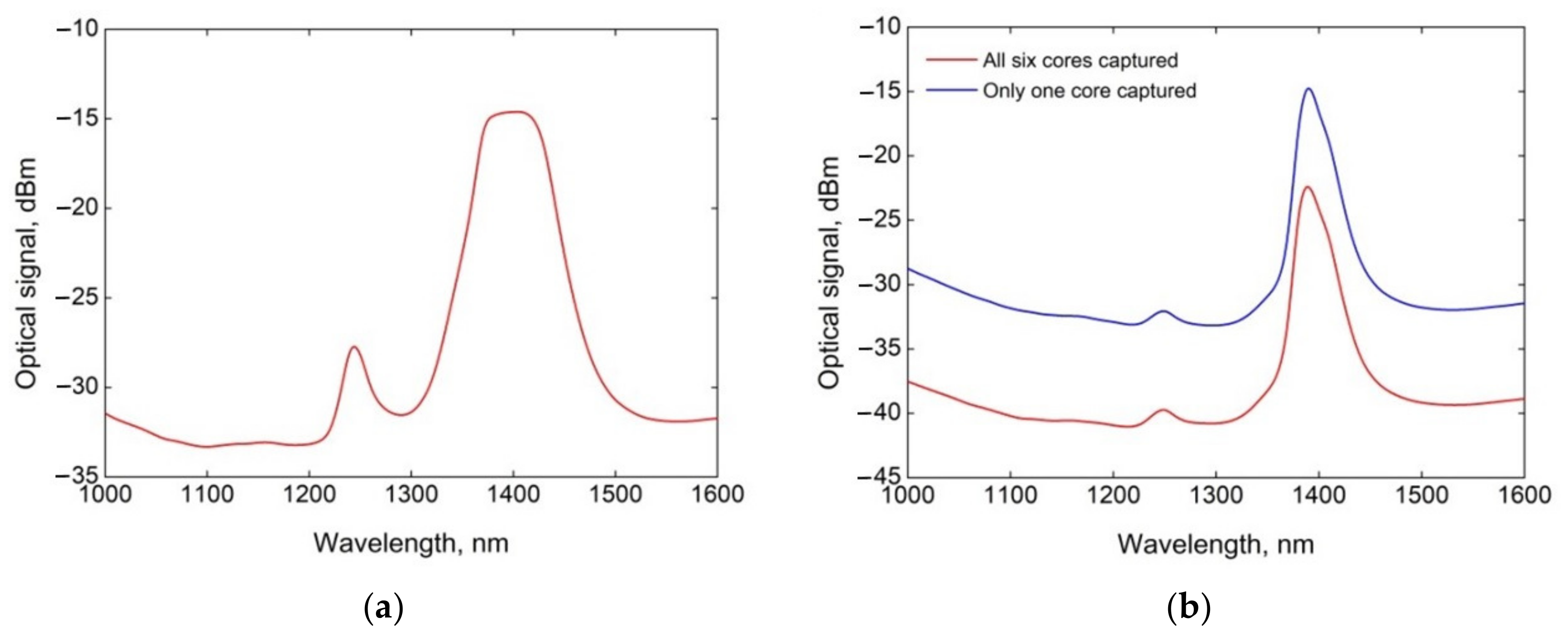
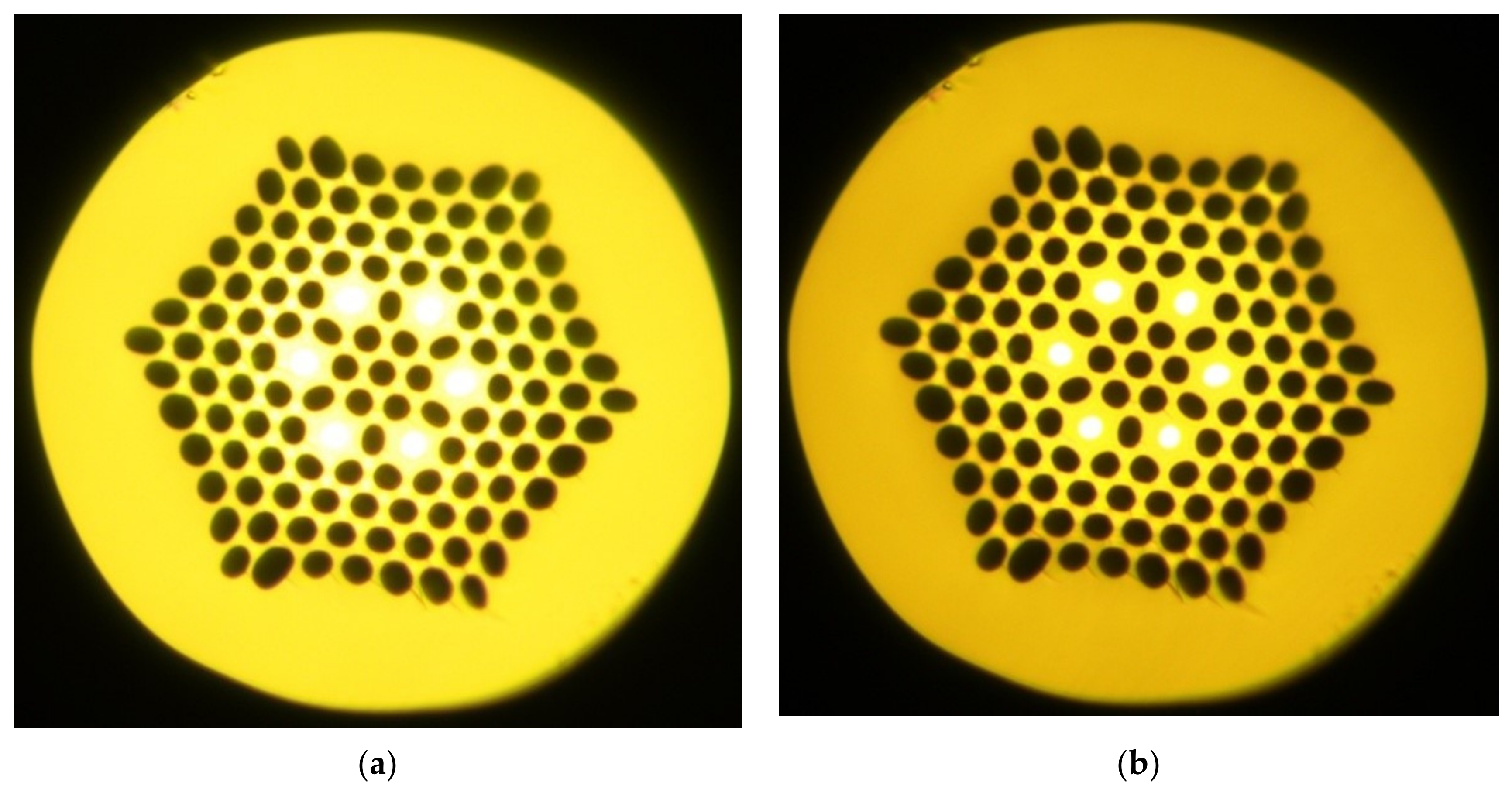
3.2. Analysis of the Six-Core-MOF Based on the Supporting Elements with Graded-Index Profile

In order to predict waveguide properties of the MOFs with the predetermined structure, we performed a series of computations and numerical simulations based on the commercially available software COMSOL Multiphysics, utilizing the finite element method. We used desired geometrical parameters of the six-core-MOF, namely a diameter of the air holes of 5 µm, a pitch (air-hole-to-air-hole distance) of 7.7 µm, and a k-parameter (air hole diameter to pitch ratio) of approximately 0.65. Such a k-parameter should guarantee the excitation of at least four spatial modes at a wavelength of 1.55 µm.
During our computations, we varied the GeO2 concentration in each of the six cores, assuming that when this parameter is exceeded, the number of spatial modes will be larger than four. Therefore, the GeO2 concentration should be tightly regulated, providing a simultaneously limited number of modes and enhancement in optical activity while the MOF is twisted. The results of the computation of waveguide properties of the desired six-core-MOF are presented in Figure 7.
Figure 8 illustrates the radial mode field distributions, computed for eight guided polarization modes, propagating without cutoff, calculated for the selected six-core-MOF (Δn = 0.0275 or at a GeO2 concentration of 16.80%).

3.3. Six-Core-MOFs Based on the Core Elements with Graded-Index Refractive Index Profile

Images of the successfully fabricated chiral six-core-MOFs with core elements drawn from the preform with the customized graded-index profile and low order (50 and 100 rpm) induced twisting are shown in Figure 9.
Transmission spectra are presented in Figure 10. We researched the wavelength band λ = 1000…1600 nm by using a halogen lamp as a light source, a programmable monochromator, a germanium photodiode, an optical amplifier, and an optical power meter. Here, the lengths of the tested MOFs with induced twistings of 50 and 100 rpm were 5 m. Strong improvement in optical signal power level during all six-core excitation (MOF end face radially overfilled launching conditions) should be noticed (Figure 10b—red line) in comparison to only one core excitation (Figure 10b—blue line). This fact may be considered as confirmation of weak mode coupling, propagating in neighboring cores, that may be improved by induced longitudinal chirality (e.g., twisting). Additionally, typical “water peaks”—strong increasing silica MOF attenuation at resonance wavelengths 1240 and 1380 nm due to OH ion absorption—can be noticed.
Images of another series of fabricated twisted six-core-MOF sample fragments, based on the core supporting elements, also drawn from the preform with the customized graded-index profile, are shown in Figure 11. This set of MOFs differs by improved twist rate up to 400…500 rpm. Transmission spectra are presented in Figure 12. Unlike weakly twisted MOFs, here, water peaks are almost missed. This fact may be considered a confirmation of the assumption about the increase in mode field distribution contraction from the periphery MOF cross-section to the core centers under improved twisting. As mentioned above, graded-index GeO2-doped core elements were drawn from the rod blank, fabricated from high-purity fused silica glass with a specified OH content below 1 ppm, while the main part of the designed MOF (stack with capillaries and rods) was prepared from silica with high OH-group concentration (more 1000 ppm). Therefore, water peaks on transmission spectra of weakly twisted MOFs indicate, that the main part of the launched optical signal transfers over pure silica zones of MOFs fabricated from “water” silica glass while smoothing the transmission spectra curves, measured for MOFs with strong twisting, may be considered as confirmations of mode field “concentration” in the GeO2-doped cores.

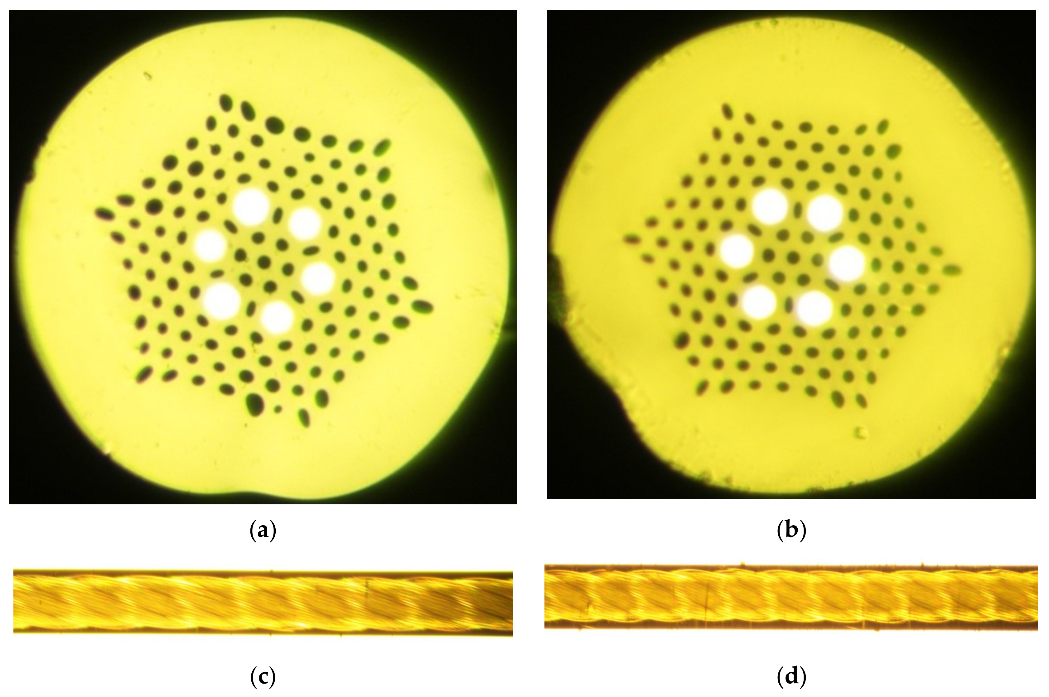
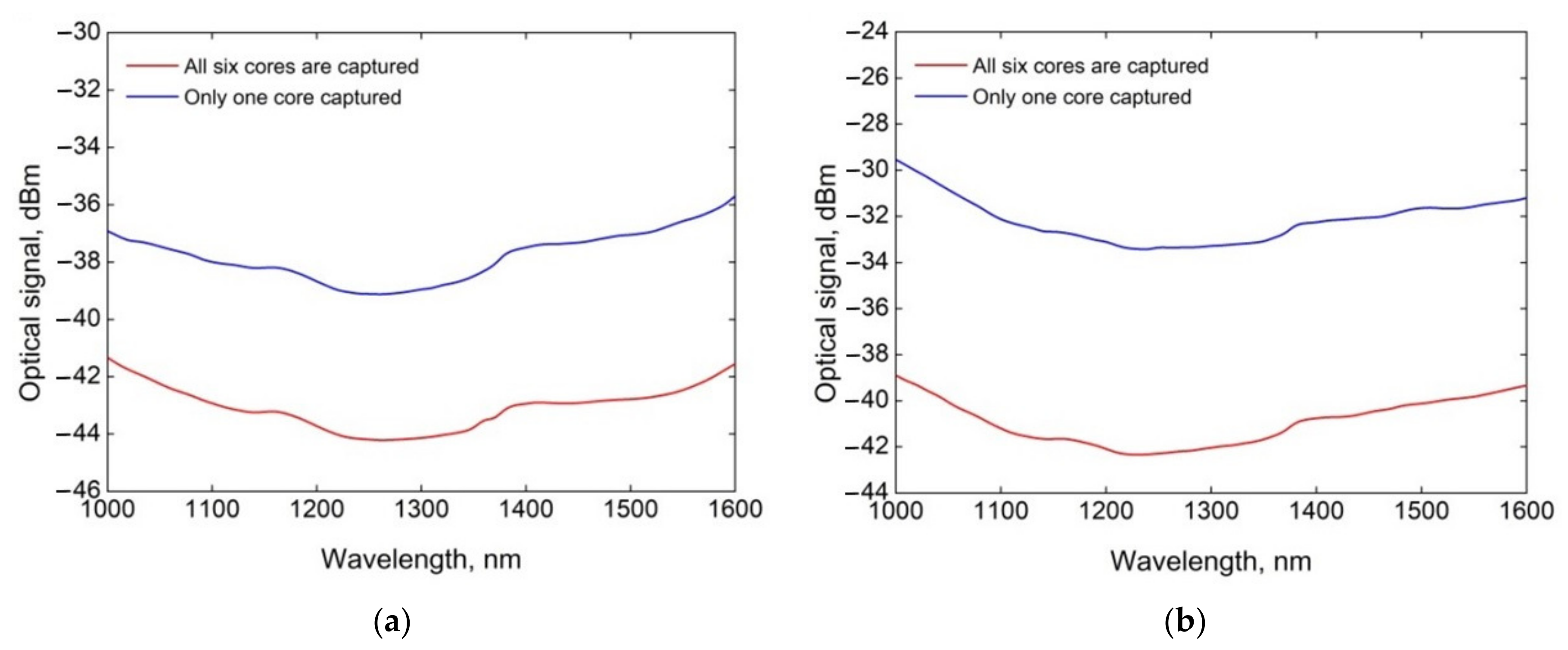
3.4. Six-Core-MOFs Based on the Core Elements with Step-Index Refractive Index Profile

Images of fabricated twisted six-core-MOF cross-sections with core elements, drawn from the preform with the step-index profile are shown in Figure 13. Here we paid attention for fabrication of MOF samples with a high rotation speeds of 470 and 570 rpm. Transmission spectra are presented in Figure 14.
According to mentioned above, unlike to twisted MOFs with graded-index 6 GeO2-doped cores, been fabricated from high-purity fused silica glass with low (below 1 ppm) OH content, here quasi-step-index GeO2-doped cores as well as other MOF supporting elements (micro-rods and capillaries) were prepared from low-cost silica glass with high OH-group concentration (more 1000 ppm). So, unlike to strongly twisted MOFs with graded-index cores, transmission spectra of strongly twisted MOFs with step-index cores keep contain water-peaks (due to described above high OH-group concentration). However, the difference between levels of peaks and other part of curves became strongly lower in comparison with spectra for low order twisted MOFs (Figure 14 vs. Figure 10–approximately 2.5…3.0 dB instead initial 12.5 dB). This may be also considered as confirmation, that chirality impacts on mode field contraction to core centers.
Figure 13. Six-core-MOFs with step-index core supporting elements: (a) cross-section view of the fabricated MOF with twisting 470 rpm; (b) cross-section view of the fabricated MOF with twisting 570 rpm.
Fibers 11 00028 g013
Figure 14. Six-core-MOFs with step-index core supporting elements transmission spectra: (a) MOF with a twisting of 470 rpm; (b) MOF with a twisting of 570 rpm.
Fibers 11 00028 g014

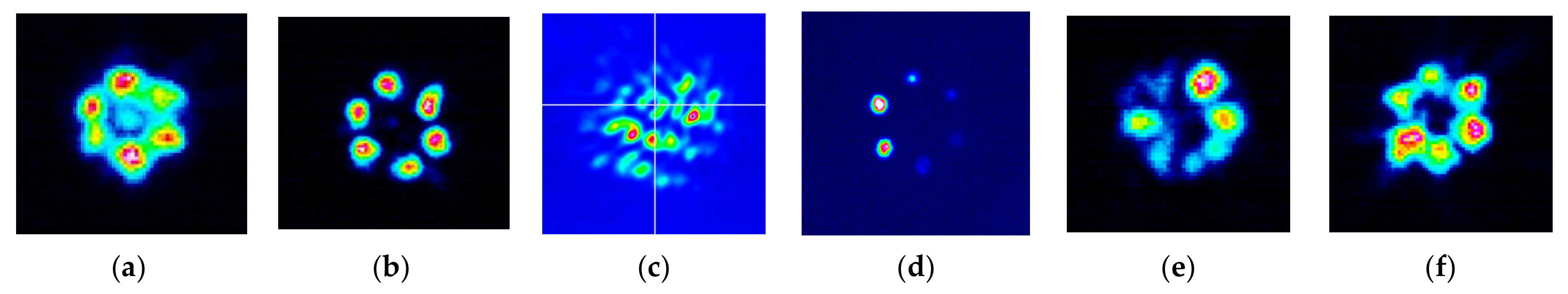
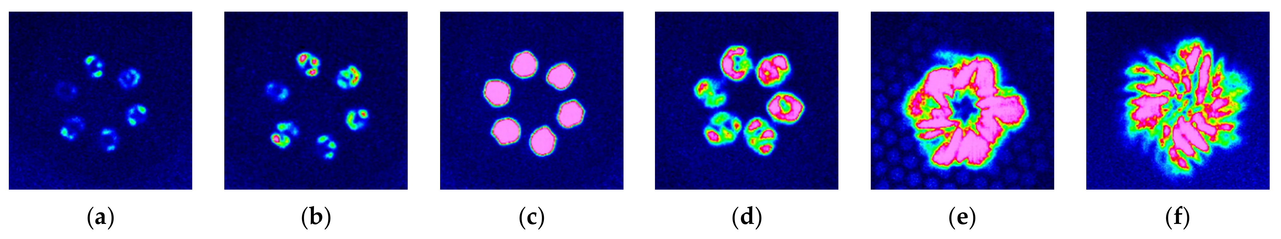
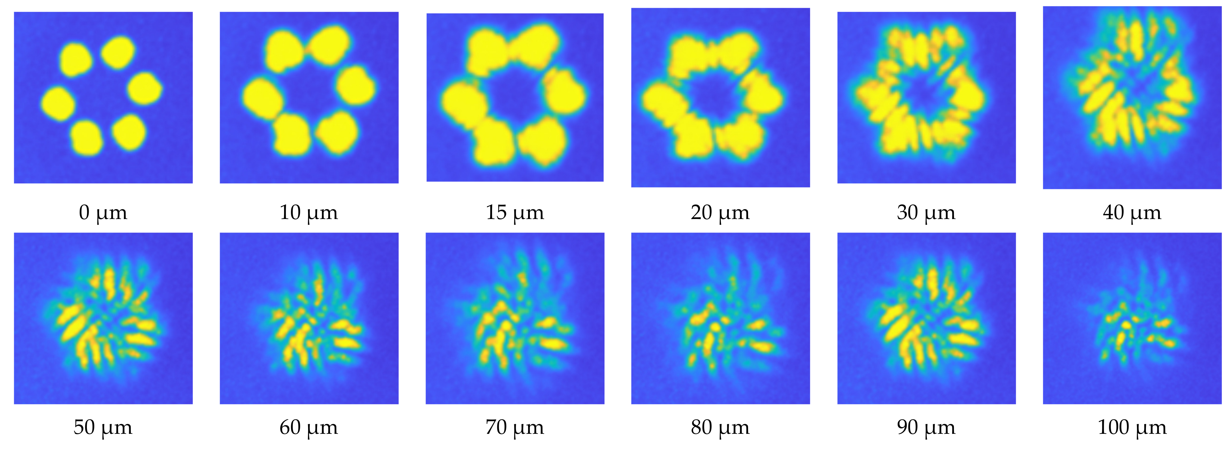
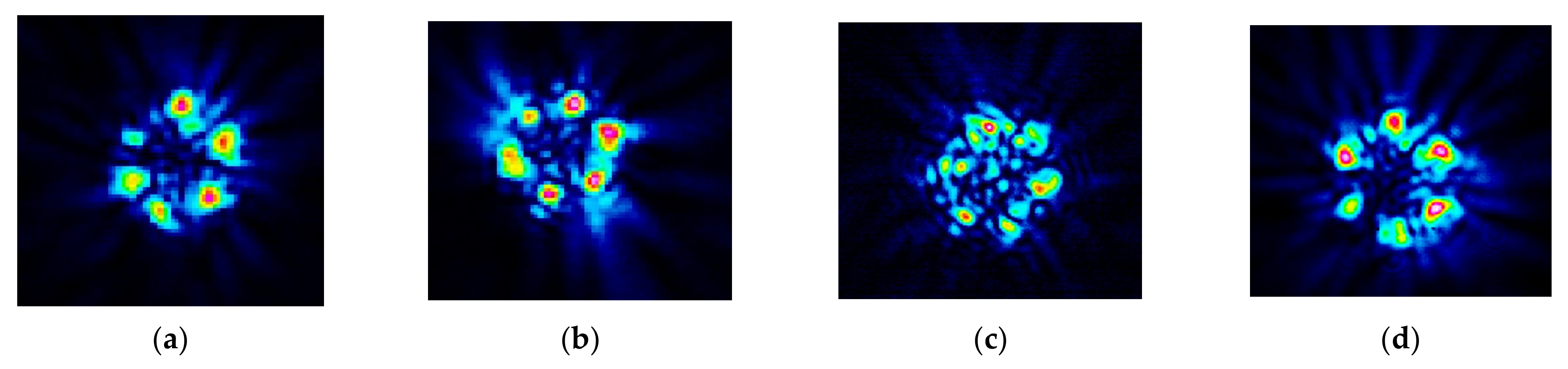
3.5. Results of Laser Beam Profile Measurements

In this section, we present some results of far-field measurements performed for the laser beam profile after propagation over the 5 m long fabricated six-core-MOF samples with various launching conditions and laser sources. These experimental studies were independently performed by three differently equipped labs of co-author research teams.
The first test series was performed for graded-index six-core-MOF under free space overfilled launching (OFL) conditions by using a focusing system containing a plane-parallel laser beam former and focusing objective. We utilized a semiconductor laser (SL) operating at a wavelength of λ = 1550 nm. The MOF end face was prepared by a cleaver tool with quality control by a microscope. The results of beam profile measurements are presented in Figure 15a,b for both 50 rpm and 100 rpm twisted graded-index six-core-MOFs, respectively. Here, once again, the improvement in twisting order demonstrates the effect of mode field “contraction” to core centers.
During the next test series, we performed the launching of laser-excited optical emission (λ = 1550 nm) to MOF via 1 m long pig-tails with graded-index multimode optical fibers (MMFs) with an outer cladding diameter of 125 µm and core diameters of 50 and 100 µm. The non-terminated pig-tail end was cleaved and directly aligned with a tested 100 rpm twisted graded-index six-core-MOF center by field commercially available fusion splicer without gaps and any misalignments. Here both MOF and MMF ends were prepared by precision fiber optic cleavers. A DFB (Distributed Feedback) laser was connected to the tested MOF via MMF 50/125, while MMF 100/125 was used for exciting by BLD source (single frequency Bragg grating laser diode). Measured beam profiles are shown in Figure 15c,d.
As expected, during launching via MMF 50/125, a typical speckle pattern at the tested MOF receiving end was detected: here, strong mode mixing and power diffusion occurred, and most of the laser-generated optical signal transferred over pure silica hole-assisted MOF center zone, while GeO2-doped core centers are located at about a 14.5 µm distance in relation to the MOF cross-section center (that is more than the laser-excited beam diameter, even after MMF 50/125 propagation and some widening).
Figure 15. Far-field laser beam profiles (λ = 1550 nm), measured at the receiving end after propagation over 5 m long twisted graded-index six-core-MOFs: (a) 50 rpm, SL, free space; (b) 100 rpm, SL, free space; (c) 100 rpm, DFB laser, MMF 50/125; (d) 100 rpm, BLD, MMF 100/125; (e) 50 rpm, SL, SMF free space; (f) 100 rpm, SL, SMF free space.
Fibers 11 00028 g015
MMF 100/125, on the contrary, provided delivery of optical emission to GeO2-doped core centers by its great core diameter. However, because the laser-excited narrow beam was initially launched to MMF 100/125, only a small part of the emission was delivered to the MOF GeO2-doped cores after propagation over MMF 100/125 with some widening of the beam. Therefore, the resulting detected laser beam profile pattern at the receiving end of the tested MOF was weak.
The next set of measurements (Figure 15e,d) was made for laser-generated emission launching to MOF via standard single-mode optical fiber (SMF, ITU-T Rec. G.652), aligned with tested MOF over free space with an air gap of about 150…200 µm. Here, we used SL, and both the MOF and SMF ends were prepared by a cleaver tool with quality control by a microscope, while aligning was performed by the above-described focusing system.
The comparison of all six detected laser beam profile patterns shown in Figure 15 demonstrates the efficiency of the OFL conditions in comparison with a connection via large core MMFs. Therefore, the next test series was focused on studies of laser connections to the tested MOF via SMF under OFL. Here the BLD source was connected to a 100 rpm twisted graded-index GeO2-doped six-core-MOF via pig-tail with SMF. The end faces of both optical fibers were prepared by a precise commercially available fiber optic cleaver. SMF and MOF center aligning with a desired 150…200 µm air gap for OFL conditions were set by the field fusion splicer. During the first three tests, we measured the beam profile under various BLD source output powers (Figure 16a–c—according to specification, maximal is 100 mW) to detect the optimal operation mode that provides a strong enough intensity of launched optical emission to receive a high-quality and detailed laser beam profile pattern. Then, we fixed the output power (at the medium order) and made some variations in the distance between the tested MOF receiving end and the IR camera objective by using a three-axis micropositioner (Figure 16d–f). Here, a 0 µm distance corresponded to a maximal contrast of the detected MOF end-face image (Figure 16d), while further increases in the distance modified the laser beam pattern and added some interferometric/optical vortex-like effects. During the next stage of research, we tested the same setup (BLD, OFL conditions via SMF, 100 rpm twisted graded-index GeO2-doped six-core-MOF) and measured laser beam profile pattern dynamics by varying the distance between the receiving end face of the tested MOF and the IR-camera objective over the range of 0…100 µm, which is presented in Figure 17. Here, under a distance of more than 30 µm, the pattern is modified by some interferometric effects.
The last (additional) test series included measurements performed for a low-wavelength (λ = 980 nm) laser beam profile after propagation over a 5 m long six-core-MOF with both a graded- and step-index. Here, we utilized special SMF with a shifted cut-off condition, providing single-mode operation at a wavelength of λ = 980 nm. The special SMF was connected to SL and aligned to the tested MOF by using the above-described focusing system (over free space, also with an air gap to provide OFL conditions). Both the MOF and special SMF end faces were cleaved by a cleaving tool with quality control by a microscope. Measured beam profiles at the receiving end of both the graded- and step-index six-core-MOFs with twistings of 50 and 100 rpm are shown in Figure 18. Here, the tested MOF excitation by a low-wavelength laser source led to an improved propagating mode number. This made the detected beam profile more similar to the MMF speckle pattern (especially for the step-index six-core-MOF—Figure 18c), while under an improvement in the twisting order, the pattern becomes somewhat more “clear” (Figure 18b,d).

4. Conclusions

This work presents designed and fabricated samples of new silica few-mode twisted multicore MOFs with six-GeO2-doped cores (both graded- and step-index), an outer diameter of 125 µm, and induced chirality with twisting up to 500…570 rpm (or, e.g., a twisting speed of 1000 revolutions per minute under a drawing speed of ~2 m per minute). Some technological issues and the fabrication of described complicated MOFs are discussed.
We presented the results of the tests performed with pilot samples of described above designed and manufactured MOFs, including their geometrical parameters and basic transmission characteristics, as well as measurements of far-field laser beam profiles. We experimentally verified that the inclusion of silica GeO2-doped supporting elements in the MOF structure under MOF twisting order improvement would provide contraction (e.g., focusing) of the radial mode field distribution to the core centers. By analyzing a set of measured laser beam profiles, optimal launching conditions were detected: first of all, OFL is required. Increasing the distance between the tested MOF receiving end and the camera objective by up to about 30 µm and more modifies the beam profile pattern and adds some interferometric effects to it.
Detailed research of the presented twisted few-mode six-core-MOF properties for utilization in various applications in measurements/sensors or/and laser systems, telecommunications, etc., require their customization as well as an additional series of tests and experiments in future works.

Author Contributions

Conceptualization, A.V.B., V.V.D., O.G.M., G.S., M.T., and J.Y.; methodology, A.V.B., K.V.D., Y.I., O.G.M., F.P., and J.Y.; investigation, A.V.B., V.V.D., K.V.D., A.V.K., A.S.M., G.A.P., E.V.T.-N., S.V.B., M.V.D., A.S.E., and E.S.Z.; validation, V.V.D., A.V.K., A.S.M., G.A.P., E.V.T.-N., A.A.K., I.I.N., M.V.D., E.S.Z., A.A.V., A.R.G., and I.K.M.; resources, A.V.B., V.V.D., and M.V.D.; writing—original draft, A.V.B. and O.G.M.; writing—review and editing, A.V.B., V.V.D., O.G.M., I.I.N., A.Z.S., and T.A.A.; visualization, A.V.B. and V.V.D.; supervision, A.V.B. and O.G.M.; project administration, A.V.B. All authors have read and agreed to the published version of the manuscript.

Funding

This research was funded by RFBR, DST, NSFC, and NRF according to the research project 19-57-80016 BRICS_t. The work is carried out in accordance with the Strategic Academic Leadership Program “Priority 2030” of the Kazan Federal University of the Government of the Russian Federation.

Institutional Review Board Statement

Not applicable.

Informed Consent Statement

Not applicable.

Data Availability Statement

The data presented in this study are available on request from the corresponding author. The data are not publicly available because they are still being collected, compared, and analyzed for the set of fabricated pilot samples of twisted MOFs with various configurations.

Conflicts of Interest

The authors declare no conflict of interest. The funders had no role in the design of the study; in the collection, analyses, or interpretation of data; in the writing of the manuscript; or in the decision to publish the results.

References

  1. Barlow, A.J.; Ramskov-Hansen, J.J.; Payne, D.N. Birefringence and polarization mode dispersion in spun single-mode fibers. Appl. Opt. 1981, 20, 2962–2968. [Google Scholar] [CrossRef] [PubMed]
  2. Hart, A.C., Jr.; Huff, R.G.; Walker, K.L. Method of Making a Fiber Having Low Polarization Mode Dispersion Due to a Permanent Spin. U.S. Patent 5298047, 29 March 1994. [Google Scholar]
  3. Blaszyk, P.E.; Christoff, W.R.; Gallagher, D.E.; Hawk, R.M.; Kiefer, W.J. Method and Apparatus for Introducing Controlled Spin in Optical Fibers. U.S. Patent 6324872 B1, 4 December 2001. [Google Scholar]
  4. Li, M.-J.; Chen, X.; Nolan, D.A. Fiber spinning for reducing polarization mode dispersion in single-mode fibers: Theory and applications. Proc. SPIE 2003, 5247, 97–110. [Google Scholar]
  5. DiGiovanni, D.J.; Golowich, S.E.; Jones, S.L.; Reed, W.A. Method of Making an Improved Multimode Optical Fiber and Fiber Made by Method. U.S. Patent 2001019652 A1, 6 September 2001. [Google Scholar]
  6. DiGiovanny, D.J.; DiMarcello, F.V.; Jiang, X.L.; Oulundsen, G.E.; Pandit, S.P. Multimode Optical Fiber with Increased Bandwidth. U.S. Patent 2004228590 A1, 18 November 2004. [Google Scholar]
  7. Ye, C.; Koponen, J.; Sosnowski, T. Spun Non-Circular and Non-Elliptical Core Optical Fibers and Apparatuses Utilizing the Same. U.S. Patent 2014/0268310 A1, 18 September 2014. [Google Scholar]
  8. Koska, P.; Peterka, P.; Doya, V. Numerical modeling of pump absorption in coiled and twisted double-clad fibers. IEEE J. Sel. Top. Quantum Electron. 2016, 22, 4401508. [Google Scholar] [CrossRef]
  9. Wong, G.K.L.; Beravat, R.; Russell, P.S.J. Helically twisted photonic crystal fibres. Philos. Trans. R. Soc. A Math. Phys. Eng. Sci. 2017, 375, 20150440. [Google Scholar]
  10. Fuochi, M.; Hayes, J.R.; Furusawa, K.; Belardi, W.; Baggett, J.C.; Monro, T.M.; Richardson, D.J. Polarization mode dispersion reduction in spun large mode area silica holey fibres. Opt. Express 2004, 12, 1972–1977. [Google Scholar] [CrossRef] [Green Version]
  11. Weiss, T.; Wong, G.K.L.; Biancalana, F.; Barnett, S.M.; Xi, X.M.; Russell, P.S.J. Topological Zeeman effect and circular birefringence in twisted photonic crystal fibers. J. Opt. Soc. Am. B. 2013, 30, 2921–2927. [Google Scholar] [CrossRef] [Green Version]
  12. Xi, X.M.; Weiss, T.; Wong, G.K.L.; Biancalana, F.; Barnett, S.M.; Padgett, M.J.; Russell, P.S.J. Optical activity in twisted solid-core photonic crystal fibers. Phys. Rev. Lett. 2013, 110, 143903. [Google Scholar] [CrossRef] [Green Version]
  13. Wong, G.K.L.; Xi, X.M.; Frosz, M.H.; Russell, P.S.J. Enhanced optical activity and circular dichroism in twisted photonic crystal fiber. Opt. Lett. 2015, 40, 4639–4642. [Google Scholar] [CrossRef]
  14. Alexeyev, C.N.; Lapin, B.P.; Milione, G.; Yavorsky, M.A. Optical activity in multihelicoidal optical fibers. Phys. Rev. A 2015, 92, 033809. [Google Scholar] [CrossRef]
  15. Alexeyev, C.N.; Lapin, B.P.; Milione, G.; Yavorsky, M.A. Resonance optical activity in multihelicoidal optical fibers. Opt. Lett. 2016, 41, 962–965. [Google Scholar] [CrossRef]
  16. Xi, X.M.; Wong, G.K.L.; Weiss, T.; Russell, P.S.J. Measuring mechanical strain and twist using helical photonic crystal fiber. Opt. Lett. 2013, 38, 5401–5404. [Google Scholar] [CrossRef]
  17. Napiorkowski, M.; Zolnacz, K.; Statkiewicz-Barabach, G.; Bernas, M.; Kiczor, A.; Mergo, P.; Urbanczyk, W. Twist induced mode confinement in partially open ring of holes. J. Light. Technol. 2020, 38, 1372–1381. [Google Scholar] [CrossRef]
  18. Zhang, M.; Zhang, L.; Chen, O.; Bai, G.; Li, S. A designed twist sensor based on the SPR effect in the thin-gold-film-coated helical microstructured optical fibers. Sensors 2022, 22, 5668. [Google Scholar] [CrossRef]
  19. Bohnert, K.; Gabus, P.; Kostovic, J.; Brandle, H. Optical fiber sensors for the electric power industry. Opt. Lasers Eng. 2005, 43, 511–526. [Google Scholar] [CrossRef]
  20. Ma, X.; Zhu, C.; Hu, I.-N.; Kaplan, A.; Galvanauskas, A. Single-mode chirally-coupled-core fibers with larger than 50 μm diameter cores. Opt. Express 2014, 22, 9206–9219. [Google Scholar] [CrossRef]
  21. Wong, G.K.L.; Kang, M.S.; Lee, H.W.; Biancalana, F.; Conti, C.; Weiss, T.; Russell, P.S.J. Excitation of orbital angular momentum resonances in helically twisted photonic crystal fiber. Science 2012, 337, 446–449. [Google Scholar] [CrossRef]
  22. Willner, A.E.; Huang, H.; Yan, Y.; Ren, Y.; Ahmed, N.; Xie, G.; Bao, C.; Li, L.; Cao, Y.; Zhao, Z.; et al. Optical communications using orbital angular momentum beams. Adv. Opt. Photonics 2015, 7, 66–106. [Google Scholar] [CrossRef] [Green Version]
  23. Barshak, E.V.; Alexeyev, C.N.; Lapin, B.P.; Yavorsky, M.A. Twisted anisotropic fibers for robust orbital-angular-momentum-based information transmission. Phys. Rev. A 2015, 91, 033833. [Google Scholar] [CrossRef]
  24. Stefani, A.; Kuhlmey, B.T.; Fleming, S. Orbital angular momentum modes by twisting of a hollow core antiresonant fiber. In Proceedings of the 2017 European Conference on Lasers and Electro-Optics and European Quantum Electronics Conference, Munich, Germany, 25–29 June 2017. CC_5_6-1. [Google Scholar]
  25. Stefani, A.; Fleming, S.C.; Kuhlmey, B.T. Terahertz orbital angular momentum modes with flexible twisted hollow core antiresonant fiber. APL Photonics 2018, 3, 051708. [Google Scholar] [CrossRef] [Green Version]
  26. Napiórkowski, M.; Urbanczyk, W. The effect of coupling between core and cladding modes in twisted microstructured optical fibers. Proc. SPIE 2018, 10681, 84–90. [Google Scholar]
  27. Fu, C.; Liu, S.; Wang, Y.; Bai, Z.; He, J.; Liao, C.; Zhang, C.; Zhang, F.; Yu, B.; Gao, S.; et al. High-order orbital angular momentum mode generator based on twisted photonic crystal fiber. Opt. Lett. 2018, 43, 1786–1789. [Google Scholar] [CrossRef] [PubMed] [Green Version]
  28. Cui, Y.; Ye, J.; Li, Y.; Dai, P.; Qu, S. Vortex chirality-dependent filtering in helically twisted single-ring photonic crystal fibers. Opt. Express 2019, 27, 20816–20823. [Google Scholar] [CrossRef] [PubMed]
  29. Zhou, G.; Liu, J.; Xia, C.; Hou, Z. Orbital-angular-momentum-amplifying helical vector modes in Yb3+-doped three-core twisted microstructure fiber. Opt. Express 2020, 28, 21110–221119. [Google Scholar]
  30. Zhang, Y.; Li, B.; Xia, C.; Hou, Z.; Zhou, G. Orbit angular momentum supermode in chirality helical dual-core microstructure fiber. Opt. Commun. 2020, 475, 126245. [Google Scholar] [CrossRef]
  31. Cui, M.; Mo, Z.; Zhao, N.; Xia, C.; Hou, Z.; Zhou, G. High-order orbital angular momentum generation in a helically twisted pig-nose-shaped core microstructured optical fiber. Opt. Express 2021, 29, 6542–6552. [Google Scholar] [CrossRef]
  32. Bourdine, A.V.; Barashkin, A.Y.; Burdin, V.A.; Dashkov, M.V.; Demidov, V.V.; Dukelskii, K.V.; Evtushenko, A.S.; Ismail, Y.; Khokhlov, A.V.; Kuznetsov, A.A.; et al. Twisted silica microstructured optical fiber with equiangular spiral six-ray geometry. Fibers 2021, 9, 27. [Google Scholar] [CrossRef]
  33. Bourdine, A.V.; Demidov, V.V.; Kuznetsov, A.A.; Vasilets, A.A.; Ter-Nersesyants, E.V.; Khokhlov, A.V.; Matrosova, A.S.; Pchelkin, G.A.; Dashkov, M.V.; Zaitseva, E.S.; et al. Twisted few-mode optical fiber with improved height of quasi-step refractive index profile. Sensors 2021, 22, 3124. [Google Scholar] [CrossRef]
  34. Bourdine, A.V.; Dashkov, M.V.; Kuznetsov, A.A.; Demidov, V.V.; Evtushenko, A.S.; Barashkin, A.Y.; Ter-Nersesyants, E.V.; Vasilets, A.A.; Morozov, O.G.; Burdin, V.A.; et al. Pulse and spectral responses of laser-excited twisted silica few-mode optical fiber with improved height of quasi-step refractive index profile. Proc. SPIE 2021, 12295, 51–61. [Google Scholar]
  35. Bourdine, A.V.; Barashkin, A.Y.; Burdin, V.A.; Dashkov, M.V.; Demidov, V.V.; Khokhlov, A.V.; Ter-Nersesyants, E.V.; Matrosova, A.S.; Pchelkin, G.A.; Dukelskii, K.V.; et al. Researches of parameters of chiral few-mode optical fiber pilot sample with improved height of step refractive index profile. Proc. Telecommun. Univ. 2021, 7, 37–49. [Google Scholar] [CrossRef]
  36. Bourdine, A.V.; Burdin, V.A.; Demidov, V.V.; Dukelskii, K.V.; Gizatulin, A.R.; Khokhlov, A.V.; Meshkov, I.K.; Sultanov, A.K.; Ter-Nersesyants, E.V.; Ustinov, S.V.; et al. Design of vortex optical fibers for RoF systems: Part II: Pilot samples of chiral microstructured optical fibers. Proc. SPIE 2020, 11516, 522–528. [Google Scholar]
Figure 1. Previously performed modifications to the drawing tower feed unit: (a) top of the feed unit with installed stepper motor that rotates a preform under desired speed; (b) completed and jointed fluoroplastic rotational adapter with installed MOF cane; (c) removed supporting pad with stepper motor and its driving system.
Fibers 11 00028 g001
Figure 2. Installation of commutator motor: (a) lightweight aluminum carrier for the commutator motor; (b) drive belt and protective shroud; (c) general view of modified drawing tower feed unit with installed commutator motor.
Fibers 11 00028 g002
Figure 3. Special device for additional fixing of MOF cane to prevent its strong vibrations under a rotation speed of more than 300 revolutions per minute.
Fibers 11 00028 g003
Figure 7. Calculated number of modes (a) and refractive index difference between the first and second excited modes (b) depending on the GeO2 concentration of the six-core-MOF based on the core elements with graded-index profile.
Fibers 11 00028 g007
Figure 8. Computed radial mode field distributions of eight guided polarization modes, propagating without cutoff, in the selected six-core-MOF: (a) LP01-like; (bd) LP11-like; (e,f) LP21-like; (g) LP02-like; (h) LP31-like.
Fibers 11 00028 g008
Figure 9. Twisted six-core-MOFs with graded-index cores as supporting elements: (a) cross-sectional view of the fabricated MOF with a twisting of 50 rpm; (b) cross-sectional view of the fabricated MOF with a twisting of 100 rpm; (c) longitudinal view of the fabricated MOF with a twisting of 50 rpm; (d) longitudinal view of the fabricated MOF with a twisting of 100 rpm.
Fibers 11 00028 g009
Figure 10. Transmission spectra of six-core-MOFs with graded-index core supporting elements: (a) MOF with a twisting of 50 rpm; (b) MOF with a twisting of 100 rpm.
Fibers 11 00028 g010
Figure 11. Strongly twisted six-core-MOFs with graded-index core supporting elements: (a) cross-section view of the fabricated MOF with twisting 400 rpm; (b) cross-section view of the fabricated MOF with twisting 500 rpm; (c) longitudinal view of the fabricated MOF with twisting 400 rpm; (d) longitudinal view of the fabricated MOF with twisting 500 rpm.
Fibers 11 00028 g011
Figure 12. Transmission spectra of six-core-MOFs with graded-index core supporting elements: (a) MOF with twisting 400 rpm; (b) MOF with twisting 500 rpm.
Fibers 11 00028 g012
Figure 16. Far-field laser beam profiles, measured at the receiving end after propagation over 5 m long 100 rpm twisted graded-index six-core-MOF, connected to BLD source (λ = 1550 nm) via SMF with an air gap of 150…200 µm to provide OFL conditions under various laser-excited emission intensities and distances between the MOF receiving end and the IR-camera objective: (a) low intensity, 0 µm; (b) medium intensity, 0 µm; (c) maximal intensity, 0 µm; (d) medium intensity, 20 µm; (e) medium intensity, 40 µm; (f) medium intensity, 70 µm.
Fibers 11 00028 g016
Figure 17. Dynamics of laser beam profile pattern, measured at the receiving end after propagation over 5 m long 100 rpm twisted graded-index six-core-MOF, connected to BLD source (λ = 1550 nm) via SMF OFL conditions over the researched range of distances between the MOF receiving end and the IR-camera objective of 0…100 µm.
Fibers 11 00028 g017
Figure 18. Far-field laser beam profiles, measured at the receiving end after propagation over 5 m long twisted six-core-MOF, connected to SL (λ = 980 nm) via special SMF with air gap 150…200 µm to provide OFL conditions: (a) 50 rpm twisted graded-index six-core-MOF; (b) 100 rpm twisted graded-index six-core-MOF; (c) 50 rpm twisted step-index six-core-MOF; (d) 100 rpm twisted step-index six-core-MOF.
Fibers 11 00028 g018
Table 1. Geometrical and optical parameters of rod blanks.
#ParameterGraded-Index Rod BlankQuasi-Step-Index Rod Blank
1Diameter (mm)28.711.2
2Diameter core/cladding ratio0.80.4
3Numerical aperture0.2680.296
4Core-cladding refractive index difference (Δn)0.02750.0360
5GeO2-dopant concentration (mol %) 16.820.5
Disclaimer/Publisher’s Note: The statements, opinions and data contained in all publications are solely those of the individual author(s) and contributor(s) and not of MDPI and/or the editor(s). MDPI and/or the editor(s) disclaim responsibility for any injury to people or property resulting from any ideas, methods, instructions or products referred to in the content.

