State of the Art in Directed Energy Deposition: From Additive Manufacturing to Materials Design


Abstract
:1. Introduction
Metal and Alloy Systems
2. DED Process Variables and Modelling Efforts
2.1. Overview of Powder-Fed DED Process Physics and Thermal History
2.2. Surface Tension and Marangoni Effect
2.3. Dimensionless Numbers
2.4. Energy Distribution in a DED System
2.5. Process–Microstructure Relationship
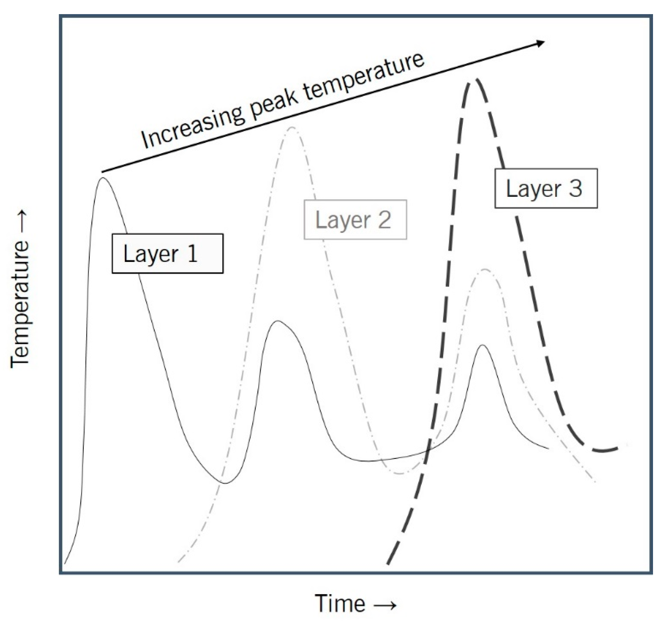
- Cooling rates as high as 13,000 K/s were recorded in the literature during in-situ process monitoring of Ti-6Al-4V with laser based DED [81]. The initial cooling rates and microstructures changed with an increase in the number of deposited layers. This may be due to the accumulation of thermal energy in the part as more layers are deposited. This is proven in a study of Ti-6Al-4V printed with laser based DED, wherein a martensite microstructure formed in the first layers slowly convert to a Widmanstaten microstructure as the layers build up [82].
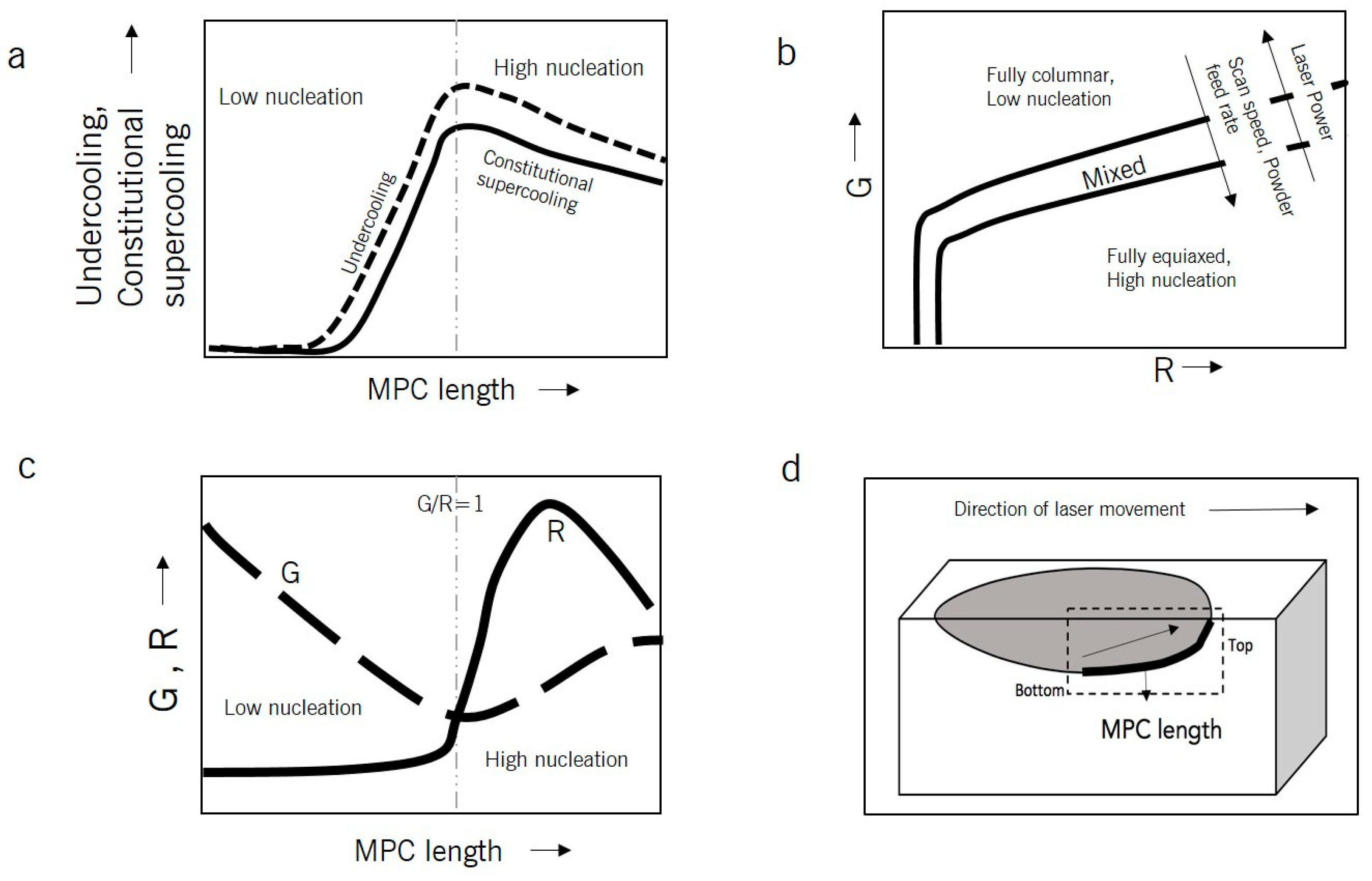
- According to the literature, the microstructure of laser based DED processed Ti-6Al-4V was columnar near the substrate (smaller MPC length) and equiaxed away from the substrate (higher MPC length) (due to differences in cooling rates), and there was a superheated melt pool during the process (almost 40%–50%) [81]. Figure 4a shows the relationship between undercooling and constitutional supercooling with respect to the MPC length.
- Heterogeneous nucleation varies with respect to the scanning speed, powder feed rate, and heat source power as shown in Figure 4b. Increases in the scanning speed and powder feed rate or decreasing the heat source power decreases the thermal gradient, G. That leads to an increase in R and a higher amount of equiaxed structure in the part.
- The ratio of G/R is an important parameter. G/R > 1 means a low rate of nucleation, due to a thermal gradient that is greater than the solidification front velocity, and G/R < 1 means a high rate of nucleation, due to a thermal gradient that is smaller than the solidification front velocity, as shown in Figure 4c.
- Figure 4d shows the MPC length, and increases in the value from the bottom to the top of the melt pool.
2.6. Dilution
3. Common Defects
3.1. Porosity
3.2. Changes in Chemical Compositions due to Solute Segregation and Loss of Alloying Elements
3.3. Printability of Alloys
4. Mechanical Properties
4.1. Tensile Strength
4.2. Hardness
4.3. Fatigue
4.4. Residual Stress
5. DED Process Control and Monitoring
6. Determination of Optimal Process Parameters for Laser Based Powder-Fed DED
7. Applications and Emerging Technologies
7.1. DED Metal Parts Used in Various Biomedical Applications
7.2. Welding and Cladding
7.3. Repair
7.4. Bulk Combinatorial Alloy Design
7.5. Construction Materials
7.6. Hybrid Additive Manufacturing
8. Summary and Outlook
Funding
Conflicts of Interest
References
- Mazumder, J. Design for metallic additive manufacturing machine with capability for “certify as you build”. Procedia CIRP 2015, 36, 187–192. [Google Scholar] [CrossRef]
- Cao, L.; Chen, S.; Wei, M.; Guo, Q.; Liang, J.; Liu, C.; Wang, M. Effect of laser energy density on defects behavior of direct laser depositing 24CrNiMo alloy steel. Opt. Laser Technol. 2019, 111, 541–553. [Google Scholar] [CrossRef]
- Khairallah, S.A.; Anderson, A.T.; Rubenchik, A.M.; King, W.E. Laser powder-bed fusion additive manufacturing: Physics of complex melt flow and formation mechanisms of pores, spatter, and denudation zones. Acta Mater. 2016, 108, 36–45. [Google Scholar] [CrossRef] [Green Version]
- Thompson, S.M.; Bian, L.; Shamsaei, N.; Yadollahi, A. An overview of Direct Laser Deposition for additive manufacturing; Part I: Transport phenomena, modeling and diagnostics. Addit. Manuf. 2015, 8, 36–62. [Google Scholar] [CrossRef]
- Caiazzo, F. Additive manufacturing by means of laser-aided directed metal deposition of titanium wire. Int. J. Adv. Manuf. Technol. 2018, 96, 2699–2707. [Google Scholar] [CrossRef] [Green Version]
- DebRoy, T.; Wei, H.L.; Zuback, J.S.; Mukherjee, T.; Elmer, J.W.; Milewski, J.O.; Beese, A.M.; Wilson-Heid, A.; De, A.; Zhang, W. Additive manufacturing of metallic components—Process, structure and properties. Prog. Mater. Sci. 2018, 92, 112–224. [Google Scholar] [CrossRef]
- Sames, W.J.; List, F.A.; Pannala, S.; Dehoff, R.R.; Babu, S.S. The Metallurgy and Processing Science of metal additive manufacturing. Int. Mater. Rev. 2016, 61, 315–360. [Google Scholar] [CrossRef]
- Gorsse, S.; Hutchinson, C.; Gouné, M.; Banerjee, R. Additive manufacturing of metals: A brief review of the characteristic microstructures and properties of steels, Ti-6Al-4V and high-entropy alloys. Sci. Technol. Adv. Mater. 2017, 18, 584–610. [Google Scholar] [CrossRef]
- Lewandowski, J.J.; Seifi, M. Metal Additive Manufacturing: A Review of Mechanical Properties. Annu. Rev. Mater. Res. 2016, 46, 151–186. [Google Scholar] [CrossRef] [Green Version]
- Harun, W.S.W.; Kamariah, M.S.I.N.; Muhamad, N.; Ghani, S.A.C.; Ahmad, F.; Mohamed, Z. A review of powder additive manufacturing processes for metallic biomaterials. Powder Technol. 2018, 327, 128–151. [Google Scholar] [CrossRef]
- Pinkerton, A.J.; Ul Haq Syed, W.; Li, L. An experimental and theoretical investigation of combined gas- and water-atomized powder deposition with a diode laser. J. Laser Appl. 2006, 18, 73–80. [Google Scholar] [CrossRef]
- Shin, Y.C.; Bailey, N.; Katinas, C.; Tan, W. Predictive modeling capabilities from incident powder and laser to mechanical properties for laser directed energy deposition. Comput. Mech. 2018, 61, 617–636. [Google Scholar] [CrossRef]
- Ramani, K.; Ramanujan, D.; Bernstein, W.Z.; Zhao, F.; Sutherland, J.; Handwerker, C.; Choi, J.-K.; Kim, H.; Thurston, D. Integrated Sustainable Life Cycle Design: A Review. J. Mech. Des. 2010, 132, 091004. [Google Scholar] [CrossRef] [Green Version]
- Greer, C.; Nycz, A.; Noakes, M.; Richardson, B.; Post, B.; Kurfess, T.; Love, L. Introduction to the design rules for Metal Big Area Additive Manufacturing. Addit. Manuf. 2019, 27, 159–166. [Google Scholar] [CrossRef]
- Heralić, A.; Christiansson, A.K.; Lennartson, B. Height control of laser metal-wire deposition based on iterative learning control and 3D scanning. Opt. Lasers Eng. 2012, 50, 1230–1241. [Google Scholar] [CrossRef]
- Zhang, L.C.; Liu, Y.; Li, S.; Hao, Y. Additive Manufacturing of Titanium Alloys by Electron Beam Melting: A Review. Adv. Eng. Mater. 2018, 20, 1–16. [Google Scholar] [CrossRef]
- Hoefer, K. Arc based additive manufacturing of steel components—Comparison of wire- and powder based variants. Weld. World 2018, 62, 243–247. [Google Scholar] [CrossRef]
- Moridi, A.; Hassani-Gangaraj, S.M.; Guagliano, M.; Dao, M. Cold spray coating: Review of material systems and future perspectives. Surf. Eng. 2014, 30, 369–395. [Google Scholar] [CrossRef]
- Hassani-Gangaraj, M.; Veysset, D.; Champagne, V.K.; Nelson, K.A.; Schuh, C.A. Adiabatic shear instability is not necessary for adhesion in cold spray. Acta Mater. 2018, 158, 430–439. [Google Scholar] [CrossRef]
- Zheng, B.; Topping, T.; Smugeresky, J.E.; Zhou, Y.; Biswas, A.; Baker, D.; Lavernia, E.J. The influence of Ni-coated TiC on laser-deposited IN625 metal matrix composites. Metall. Mater. Trans. A 2010, 41, 568–573. [Google Scholar] [CrossRef]
- Li, X.C.; Stampfl, J.; Prinz, F.B. Mechanical and thermal expansion behavior of laser deposited metal matrix composites of Invar and TiC. Mater. Sci. Eng. A 2002, 282, 86–90. [Google Scholar] [CrossRef]
- Liu, W.; DuPont, J.N. Fabrication of carbide-particle-reinforced titanium aluminide-matrix composites by laser-engineered net shaping. Metall. Mater. Trans. A 2004, 35, 1133–1140. [Google Scholar] [CrossRef] [Green Version]
- Liu, W.; DuPont, J.N. Fabrication of functionally graded TiC/Ti composites by Laser Engineered Net Shaping. Scr. Mater. 2003, 48, 1337–1342. [Google Scholar] [CrossRef]
- Gualtieri, T.; Bandyopadhyay, A. Additive manufacturing of compositionally gradient metal-ceramic structures: Stainless steel to vanadium carbide. Mater. Des. 2018, 139, 419–428. [Google Scholar] [CrossRef]
- Zhang, Y.; Bandyopadhyay, A. Direct fabrication of compositionally graded Ti-Al2O3 multi-material structures using Laser Engineered Net Shaping. Addit. Manuf. 2018, 21, 104–111. [Google Scholar] [CrossRef]
- Balla, V.K.; DeVasConCellos, P.D.; Xue, W.; Bose, S.; Bandyopadhyay, A. Fabrication of compositionally and structurally graded Ti-TiO2 structures using laser engineered net shaping (LENS). Acta Biomater. 2009, 5, 1831–1837. [Google Scholar] [CrossRef] [PubMed]
- Bandyopadhyay, P.P.; Balla, V.K.; Bose, S.; Bandyopadhyay, A. Compositionally graded aluminum oxide coatings on stainless steel using laser processing. J. Am. Ceram. Soc. 2007, 90, 1989–1991. [Google Scholar] [CrossRef]
- Das, M.; Balla, V.K.; Kumar, T.S.S.; Manna, I. Fabrication of Biomedical Implants using Laser Engineered Net Shaping (LENS™). Trans. Indian Ceram. Soc. 2013, 72, 169–174. [Google Scholar] [CrossRef]
- Heer, B.; Bandyopadhyay, A. Silica coated titanium using Laser Engineered Net Shaping for enhanced wear resistance. Addit. Manuf. 2018, 23, 303–311. [Google Scholar] [CrossRef]
- Das, M.; Balla, V.K.; Kumar, T.S.S.; Bandyopadhyay, A.; Manna, I. Tribological, electrochemical and in vitro biocompatibility properties of SiC reinforced composite coatings. Mater. Des. 2016, 95, 510–517. [Google Scholar] [CrossRef]
- Bandyopadhyay, A.; Dittrick, S.; Gualtieri, T.; Wu, J.; Bose, S. Calcium phosphate-titanium composites for articulating surfaces of load-bearing implants. J. Mech. Behav. Biomed. Mater. 2016, 57, 280–288. [Google Scholar] [CrossRef] [PubMed]
- Stenberg, K.; Dittrick, S.; Bose, S.; Bandyopadhyay, A. Influence of simultaneous addition of carbon nanotubes and calcium phosphate on wear resistance of 3D-printed Ti6Al4V. J. Mater. Res. 2018, 33, 2077–2086. [Google Scholar] [CrossRef]
- Traxel, K.D.; Bandyopadhyay, A. Reactive-deposition based additive manufacturing of Ti-Zr-BN composites. Addit. Manuf. 2018, 24, 353–363. [Google Scholar] [CrossRef]
- Ke, D.; Vu, A.A.; Bandyopadhyay, A.; Bose, S. Compositionally graded doped hydroxyapatite coating on titanium using laser and plasma spray deposition for bone implants. Acta Biomater. 2019, 84, 414–423. [Google Scholar] [CrossRef] [PubMed]
- Torgerson, T.B.; Mantri, S.A.; Banerjee, R.; Scharf, T.W. Room and elevated temperature sliding wear behavior and mechanisms of additively manufactured novel precipitation strengthened metallic composites. Wear 2019, 426, 942–951. [Google Scholar] [CrossRef]
- Srinivas, V.; Savitha, U.; Jagan Reddy, G. Processing and Characterization of NiCr-YSZ Compositionally Graded Coatings on Superalloy using Laser Engineered Net Shaping (LENS). Mater. Today Proc. 2018, 5, 27277–27284. [Google Scholar] [CrossRef]
- Hu, Y.; Wang, H.; Li, Y.; Ning, F.; Cong, W. Surface grinding of ZTA parts fabricated by laser engineered net shaping process: Effects of ZrO2 content and ultrasonic vibration. In Proceedings of the 13th International Manufacturing Science and Engineering Conference, College Station, TX, USA, 18–22 June 2018. [Google Scholar]
- Yan, J.; Masoudi, N.; Battiato, I.; Fadel, G. Optimization of process parameters in laser engineered Net shaping (LENS) deposition of multi-materials. In Proceedings of the ASME 2015 International Design Engineering Technical Conferences and Computers and Information in Engineering Conference, Boston, MA, USA, 2–5 August 2015; p. V01AT02A034. [Google Scholar]
- Zhang, Y.; Sahasrabudhe, H.; Bandyopadhyay, A. Additive manufacturing of Ti-Si-N ceramic coatings on titanium. Appl. Surf. Sci. 2015, 346, 428–437. [Google Scholar] [CrossRef]
- Bernard, S.A.; Balla, V.K.; Bose, S.; Bandyopadhyay, A. Direct laser processing of bulk lead zirconate titanate ceramics. Mater. Sci. Eng. B 2010, 172, 85–88. [Google Scholar] [CrossRef]
- Li, Y.; Hu, Y.; Cong, W.; Zhi, L.; Guo, Z. Additive manufacturing of alumina using laser engineered net shaping: Effects of deposition variables. Ceram. Int. 2017, 43, 7768–7775. [Google Scholar] [CrossRef]
- Niu, F.; Wu, D.; Zhou, S.; Ma, G. Power prediction for laser engineered net shaping of Al2O3 ceramic parts. J. Eur. Ceram. Soc. 2014, 34, 3811–3817. [Google Scholar] [CrossRef]
- Wu, D.J.; Niu, F.Y.; Ma, G.Y.; Zhang, B.; Yan, S. Process optimization for suppressing cracks in laser engineered net shaping of Al2O3 ceramics. JOM 2016, 69, 557–562. [Google Scholar]
- Ma, G.; Wang, J.; Niu, F.; Sun, B.; Wu, D. Influence of powder distribution on the Al2O3 thin-wall ceramic formed by laser engineered net shaping. Chin. J. Lasers 2015, 42, 0103006. [Google Scholar]
- Niu, F.; Wu, D.; Ma, G.; Zhang, B. Additive manufacturing of ceramic structures by laser engineered net shaping. Chin. J. Mech. Eng. 2015, 28, 1117–1122. [Google Scholar] [CrossRef]
- Wu, D.; Liu, H.; Lu, F.; Ma, G.; Yan, S.; Niu, F.; Guo, D. Al2O3-YAG eutectic ceramic prepared by laser additive manufacturing with water-cooled substrate. Ceram. Int. 2019, 45, 4119–4122. [Google Scholar] [CrossRef]
- Roy, M.; Vamsi Krishna, B.; Bandyopadhyay, A.; Bose, S. Laser processing of bioactive tricalcium phosphate coating on titanium for load-bearing implants. Acta Biomater. 2008, 4, 324–333. [Google Scholar] [CrossRef] [PubMed]
- Yan, S.; Wu, D.; Niu, F.; Huang, Y.; Liu, N.; Ma, G. Effect of ultrasonic power on forming quality of nano-sized Al2O3-ZrO2 eutectic ceramic via laser engineered net shaping (LENS). Ceram. Int. 2018, 44, 1120–1126. [Google Scholar] [CrossRef]
- Hu, Y.; Ning, F.; Cong, W.; Li, Y.; Wang, X.; Wang, H. Ultrasonic vibration-assisted laser engineering net shaping of ZrO2-Al2O3 bulk parts: Effects on crack suppression, microstructure, and mechanical properties. Ceram. Int. 2018, 44, 2752–2760. [Google Scholar] [CrossRef]
- Niu, F.; Wu, D.; Ma, G.; Wang, J.; Guo, M.; Zhang, B. Nanosized microstructure of Al2O3-ZrO2 (Y2O3) eutectics fabricated by laser engineered net shaping. Scr. Mater. 2015, 95, 39–41. [Google Scholar] [CrossRef]
- Marattukalam, J.J.; Singh, A.K.; Datta, S.; Das, M.; Balla, V.K.; Bontha, S.; Kalpathy, S.K. Microstructure and corrosion behavior of laser processed NiTi alloy. Mater. Sci. Eng. C 2015, 57, 309–313. [Google Scholar] [CrossRef]
- Stull, J.A.; Hill, M.A.; Lienert, T.J.; Tokash, J.; Bohn, K.R.; Hooks, D.E. Corrosion characteristics of laser-engineered net shaping additively-manufactured 316L stainless steel. JOM 2018, 70, 2677–2683. [Google Scholar] [CrossRef]
- Dehoff, R.R.; Sarosi, P.M.; Collins, P.C.; Fraser, H.L.; Mills, M.J. Microstructural evaluation of LENS™ deposited Nb-Ti-Si-Cr alloys. MRS Online Proc. Libr. Arch. 2002, 753, 2–7. [Google Scholar] [CrossRef]
- Sridharan, N.; Cakmak, E.; Dehoff, R.R. Microstructure evolution during laser direct energy deposition of a novel Fe-Cr-Ni-W-B hardfacing coating. Surf. Coat. Technol. 2019, 358, 362–370. [Google Scholar] [CrossRef]
- Gu, D.D.; Meiners, W.; Wissenbach, K.; Poprawe, R. Laser additive manufacturing of metallic components: Materials, processes and mechanisms. Int. Mater. Rev. 2012, 57, 133–164. [Google Scholar] [CrossRef]
- Gibson, I.; Rosen, D.; Stucker, B. Additive Manufacturing Technologies: 3D Printing, Rapid Prototyping, and Direct Digital Manufacturing, 2nd ed.; Springer: New York, NY, USA, 2015. [Google Scholar]
- DebRoy, T.; Zhang, W.; Turner, J.; Babu, S.S. Building digital twins of 3D printing machines. Scr. Mater. 2017, 135, 119–124. [Google Scholar] [CrossRef]
- Pinkerton, A.J.; Moat, R.; Shah, K.; Li, L.; Preuss, M.; Withers, P.J. A verified model of laser direct metal deposition using an analytical enthalpy balance method. In Proceedings of the International Congress on Applications of Lasers & Electro-Optics, Orlando, FL, USA, 29 October–1 November 2007. [Google Scholar]
- Liu, S.; Zhang, Y.; Kovacevic, R. Numerical simulation and experimental study of powder flow distribution in high power direct diode laser cladding process. Lasers Manuf. Mater. Process. 2015, 2, 199–218. [Google Scholar] [CrossRef]
- Heigel, J.C.; Michaleris, P.; Reutzel, E.W. Thermo-mechanical model development and validation of directed energy deposition additive manufacturing of Ti-6Al-4V. Addit. Manuf. 2015, 5, 9–19. [Google Scholar] [CrossRef]
- Kovaleva, I.; Kovalev, O.; Zaitsev, A.; Smurov, I. Numerical simulation and comparison of powder jet profiles for different types of coaxial nozzles in direct material deposition. Phys. Procedia 2013, 41, 870–872. [Google Scholar] [CrossRef]
- Tian, Y.; McAllister, D.; Colijn, H.; Mills, M.; Farson, D.; Nordin, M.; Babu, S. Rationalization of microstructure heterogeneity in INCONEL 718 builds made by the direct laser additive manufacturing process. Metall. Mater. Trans. A Phys. Metall. Mater. Sci. 2014, 45, 4470–4483. [Google Scholar] [CrossRef]
- Radhakrishnan, B.; Gorti, S.; Babu, S. Large scale phase field simulations of microstructure evolution during thermal cycling. In Proceedings of the International Conference on Solid-Solid Phase Transformations in Inorganic Materials (PTM), Whistler, BC, Canada, 28 June–3 July 2015. [Google Scholar]
- Amine, T.; Newkirk, J.W.; Liou, F. Investigation of effect of process parameters on multilayer builds by direct metal deposition. Appl. Therm. Eng. 2014, 73, 500–511. [Google Scholar] [CrossRef]
- DebRoy, T.; David, S.A. Physical processes in fusion welding. Rev. Mod. Phys. 1995, 67, 85–112. [Google Scholar] [CrossRef]
- Raghavan, A.; Wei, H.L.; Palmer, T.A.; DebRoy, T. Heat transfer and fluid flow in additive manufacturing. J. Laser Appl. 2014, 25, 052006. [Google Scholar] [CrossRef]
- Manvatkar, V.; De, A.; DebRoy, T. Spatial variation of melt pool geometry, peak temperature and solidification parameters during laser assisted additive manufacturing process. Mater. Sci. Technol. 2015, 31, 924–930. [Google Scholar] [CrossRef]
- Manvatkar, V.; De, A.; Debroy, T. Heat transfer and material flow during laser assisted multi-layer additive manufacturing. J. Appl. Phys. 2014, 116, 124905. [Google Scholar] [CrossRef] [Green Version]
- Farahmand, P.; Kovacevic, R. An experimental–numerical investigation of heat distribution and stress field in single- and multi-track laser cladding by a high-power direct diode laser. Opt. Laser Technol. 2014, 63, 154–168. [Google Scholar] [CrossRef]
- Cao, J.; Gharghouri, M.A.; Nash, P. Finite-element analysis and experimental validation of thermal residual stress and distortion in electron beam additive manufactured Ti-6Al-4V build plates. J. Mater. Process. Technol. 2016, 237, 409–419. [Google Scholar] [CrossRef]
- Heiple, C.R.; Roper, J.R.; Stagner, R.T.; Aden, R.J. Surface active element effects on the shape of GTA, laser and electron beam welds. Weld. J. 1983, 62, 72–77. [Google Scholar]
- Mills, K.C.; Keene, B.J.; Brooks, R.F.; Shirali, A. Marangoni effects in welding. Philos. Trans. R. Soc. A Math. Phys. Eng. Sci. 1998, 356, 911–925. [Google Scholar] [CrossRef]
- Aucott, L.; Dong, H.; Mirihanage, W.; Atwood, R.; Kidess, A.; Gao, S.; Wen, S.; Marsden, J.; Feng, S.; Tong, M.; et al. Revealing internal flow behaviour in arc welding and additive manufacturing of metals. Nat. Commun. 2018, 9, 1–7. [Google Scholar] [CrossRef] [Green Version]
- Mukherjee, T.; Manvatkar, V.; De, A.; DebRoy, T. Dimensionless numbers in additive manufacturing. J. Appl. Phys. 2017, 121, 024904. [Google Scholar] [CrossRef]
- Van Elsen, M.; Al-Bender, F.; Kruth, J.P. Application of dimensional analysis to selective laser melting. Rapid Prototyp. J. 2008, 14, 15–22. [Google Scholar] [CrossRef]
- Mukherjee, T.; Manvatkar, V.; De, A.; DebRoy, T. Mitigation of thermal distortion during additive manufacturing. Scr. Mater. 2017, 127, 79–83. [Google Scholar] [CrossRef] [Green Version]
- Lia, F.; Park, J.; Tressler, J.; Martukanitz, R. Partitioning of laser energy during directed energy deposition. Addit. Manuf. 2017, 18, 31–39. [Google Scholar] [CrossRef]
- Song, J.; Chew, Y.; Bi, G.; Yao, X.; Zhang, B.; Bai, J.; Moon, S.K. Numerical and experimental study of laser aided additive manufacturing for melt-pool profile and grain orientation analysis. Mater. Des. 2018, 137, 286–297. [Google Scholar] [CrossRef]
- Bontha, S.; Klingbeil, N.W.; Kobryn, P.A.; Fraser, H.L. Thermal process maps for predicting solidification microstructure in laser fabrication of thin-wall structures. J. Mater. Process. Technol. 2006, 178, 135–142. [Google Scholar] [CrossRef]
- Liu, P.; Wang, Z.; Xiao, Y.; Horstemeyer, M.F.; Cui, X.; Chen, L. Insight into the mechanisms of columnar to equiaxed grain transition during metallic additive manufacturing. Addit. Manuf. 2019, 26, 22–29. [Google Scholar] [CrossRef]
- Marshall, G.J.; Young, W.J.; Thompson, S.M.; Shamsaei, N.; Daniewicz, S.R.; Shao, S. Understanding the microstructure formation of Ti-6Al-4V during direct laser deposition via in-situ thermal monitoring. JOM 2016, 68, 778–790. [Google Scholar] [CrossRef]
- Kistler, N.A.; Corbin, D.J.; Nassar, A.R.; Reutzel, E.W.; Beese, A.M. Effect of processing conditions on the microstructure, porosity, and mechanical properties of Ti-6Al-4V repair fabricated by directed energy deposition. J. Mater. Process. Technol. 2019, 264, 172–181. [Google Scholar] [CrossRef]
- Wolff, S.J. Laser-Matter Interactions in Directed Energy Deposition; Northwestern University Press: Evanston, IL, USA, 2018. [Google Scholar]
- Spalding, I.J. Applied laser tooling. J. Mod. Opt. 2007, 35, 754–755. [Google Scholar] [CrossRef]
- Wolff, S.J.; Lin, S.; Faierson, E.J.; Liu, W.K.; Wagner, G.J.; Cao, J. A framework to link localized cooling and properties of directed energy deposition (DED)-processed Ti-6Al-4V. Acta Mater. 2017, 132, 106–117. [Google Scholar] [CrossRef] [Green Version]
- Ahsan, M.N.; Bradley, R.; Pinkerton, A.J. Microcomputed tomography analysis of intralayer porosity generation in laser direct metal deposition and its causes. J. Laser Appl. 2011, 23, 022009. [Google Scholar] [CrossRef]
- Cunningham, R.; Nicolas, A.; Madsen, J.; Fodran, E.; Anagnostou, E.; Sangid, M.D.; Rollett, A. Analyzing the effects of powder and post-processing on porosity and properties of electron beam melted Ti-6Al-4V. Mater. Res. Lett. 2017, 5, 516–525. [Google Scholar] [CrossRef] [Green Version]
- Rabin, B.H.; Smolik, G.R.; Korth, G.E. Characterization of entrapped gases in rapidly solidified powders. Mater. Sci. Eng. A 1990, 124, 1–7. [Google Scholar] [CrossRef]
- Wang, Z.; Denlinger, E.; Michaleris, P.; Stoica, A.D.; Ma, D.; Beese, A.M. Residual stress mapping in Inconel 625 fabricated through additive manufacturing: Method for neutron diffraction measurements to validate thermomechanical model predictions. Mater. Des. 2017, 113, 169–177. [Google Scholar] [CrossRef] [Green Version]
- Rafi, H.K.; Pal, D.; Patil, N.; Starr, T.L.; Stucker, B.E. Microstructure and Mechanical Behavior of 17-4 Precipitation Hardenable Steel Processed by Selective Laser Melting. J. Mater. Eng. Perform. 2014, 23, 4421–4428. [Google Scholar] [CrossRef]
- Wang, Z.; Beese, A.M. Effect of chemistry on martensitic phase transformation kinetics and resulting properties of additively manufactured stainless steel. Acta Mater. 2017, 131, 410–422. [Google Scholar] [CrossRef] [Green Version]
- Mukherjee, T.; Zuback, J.S.; De, A.; DebRoy, T. Printability of alloys for additive manufacturing. Sci. Rep. 2016, 6, 1–8. [Google Scholar] [CrossRef] [PubMed]
- Sandgren, H.R.; Zhai, Y.; Lados, D.A.; Shade, P.A.; Schuren, J.C.; Groeber, M.A.; Kenesei, P.; Gavras, A.G. Characterization of fatigue crack growth behavior in LENS fabricated Ti-6Al-4V using high-energy synchrotron x-ray microtomography. Addit. Manuf. 2016, 12, 132–141. [Google Scholar] [CrossRef] [Green Version]
- Beese, A.M.; Carroll, B.E. Review of mechanical properties of Ti-6Al-4V made by laser based additive manufacturing using powder feedstock. JOM 2016, 68, 724–734. [Google Scholar] [CrossRef]
- Carroll, B.E.; Palmer, T.A.; Beese, A.M. Anisotropic tensile behavior of Ti-6Al-4V components fabricated with directed energy deposition additive manufacturing. Acta Mater. 2015, 87, 309–320. [Google Scholar] [CrossRef]
- Shamsaei, N.; Yadollahi, A.; Bian, L.; Thompson, S.M. An overview of direct laser deposition for additive manufacturing; Part II: Mechanical behavior, process parameter optimization and control. Addit. Manuf. 2015, 8, 12–35. [Google Scholar] [CrossRef]
- Zuback, J.S.; DebRoy, T. The Hardness of Additively Manufactured Alloys. Materials 2018, 11, 2070. [Google Scholar] [CrossRef] [PubMed]
- Arcella, F.G.; Froes, F.H. Producing titanium aerospace components from powder using laser forming. JOM 2000, 52, 28–30. [Google Scholar] [CrossRef]
- Kobryn, P.A.; Semiatin, S.L. Mechanical Properties of Laser-Deposited Ti-6Al-4V; Air Force Research Laboratory: Hanscom, MA, USA, 2013. [Google Scholar]
- Zhai, Y.; Galarraga, H.; Lados, D.A. Microstructure evolution, tensile properties, and fatigue damage mechanisms in Ti-6Al-4V alloys fabricated by two additive manufacturing techniques. Procedia Eng. 2015, 114, 658–666. [Google Scholar] [CrossRef]
- Bian, L.; Thompson, S.M.; Shamsaei, N. Mechanical properties and microstructural features of direct laser-deposited Ti-6Al-4V. JOM 2015, 67, 629–638. [Google Scholar] [CrossRef]
- Nalla, R.K.; Ritchie, R.O.; Boyce, B.L.; Campbell, J.P.; Peters, J.O. Influence of microstructure on high-cycle fatigue of Ti-6Al-4V: Bimodal vs. lamellar structures. Metall. Mater. Trans. A 2002, 33, 899–918. [Google Scholar] [CrossRef]
- Prabhu, A.W.; Vincent, T.; Chaudhary, A.; Zhang, W.; Babu, S.S. Effect of microstructure and defects on fatigue behaviour of directed energy deposited Ti–6Al–4V. Sci. Technol. Weld. Join. 2015, 20, 659–669. [Google Scholar] [CrossRef]
- Kobryn, P.A.; Semiatin, S. Mechanical properties of laser-deposited Ti-6Al-4V. In Solid Freeform Fabrication Proceedings; Landes Bioscience: Austin, TX, USA, 2001. [Google Scholar]
- Zhai, Y.; Lados, D.A.; Brown, E.J.; Vigilante, G.N. Fatigue crack growth behavior and microstructural mechanisms in Ti-6Al-4V manufactured by laser engineered net shaping. Int. J. Fatigue 2016, 93, 51–63. [Google Scholar] [CrossRef]
- Li, C.; Liu, Z.Y.; Fang, X.Y.; Guo, Y.B. Residual stress in metal additive manufacturing. Procedia CIRP 2018, 71, 348–353. [Google Scholar] [CrossRef]
- NIST. Measurement Science for Additive Manufacturing Program; NIST: Gaithersburg, MD, USA, 2013.
- Kenel, C.; Grolimund, D.; Li, X.; Panepucci, E.; Samson, V.A.; Sanchez, D.F.; Marone, F.; Leinenbach, C. In situ investigation of phase transformations in Ti-6Al-4V under additive manufacturing conditions combining laser melting and high-speed micro-X-ray diffraction. Sci. Rep. 2017, 7, 1–10. [Google Scholar] [CrossRef] [Green Version]
- Wolff, S.J.; Wu, H.; Parab, N.; Zhao, C.; Ehmann, K.F.; Sun, T.; Cao, J. In-situ high-speed X-ray imaging of piezo-driven directed energy deposition additive manufacturing. Sci. Rep. 2019, 9, 1–14. [Google Scholar] [CrossRef] [Green Version]
- Koester, L.W.; Taheri, H.; Bigelow, T.A.; Bond, L.J.; Faierson, E.J. In-situ acoustic signature monitoring in additive manufacturing processes. AIP Conf. Proc. 2018, 1949, 020006. [Google Scholar] [CrossRef]
- Wang, F.; Mao, H.; Zhang, D.; Zhao, X.; Shen, Y. Online study of cracks during laser cladding process based on acoustic emission technique and finite element analysis. Appl. Surf. Sci. 2008, 255, 3267–3275. [Google Scholar] [CrossRef]
- Griffith, M.L.; Schlienger, M.E.; Harwell, L.D.; Oliver, M.S.; Baldwin, M.D.; Ensz, M.T.; Essien, M.; Brooks, J.; Robino, C.V.; Smugeresky, J.E.; et al. Understanding thermal behavior in the LENS process. Mater. Des. 1999, 20, 107–113. [Google Scholar] [CrossRef]
- Nassar, A.R.; Keist, J.S.; Reutzel, E.W.; Spurgeon, T.J. Intra-layer closed-loop control of build plan during directed energy additive manufacturing of Ti–6Al–4V. Addit. Manuf. 2015, 6, 39–52. [Google Scholar] [CrossRef]
- Wang, L.; Felicelli, S.D.; Craig, J.E. Thermal modeling and experimental validation in the LENS™ process. In Proceedings of the 18th Solid Freeform Fabrication Symposium, Austin, TX, USA, 2007; pp. 100–111. [Google Scholar]
- Hua, T.; Jing, C.; Xin, L.; Fengying, Z.; Weidong, H. Research on molten pool temperature in the process of laser rapid forming. J. Mater. Process. Technol. 2008, 198, 454–462. [Google Scholar] [CrossRef]
- Tellez, A.G.M. Fibre Laser Metal Deposition with Wire: Parameters Study and Temperature Control; University of Nottingham: Nottingham, UK, 2010. [Google Scholar]
- Yu, J.; Lin, X.; Wang, J.; Chen, J.; Huang, W. Mechanics and energy analysis on molten pool spreading during laser solid forming. Appl. Surf. Sci. 2010, 256, 4612–4620. [Google Scholar] [CrossRef]
- Hu, D.; Kovacevic, R. Sensing, modeling and control for laser based additive manufacturing. Int. J. Mach. Tools Manuf. 2003, 43, 51–60. [Google Scholar] [CrossRef]
- Gegel, M.L.; Bristow, D.A.; Landers, R.G. A Quadratic-optimal repetitive process controller for laser metal deposition. In Proceedings of the Annual American Control Conference (ACC), Seattle, WA, USA, 27–29 June 2018. [Google Scholar]
- Thomas, M.; Baxter, G.J.; Todd, I. Normalised model based processing diagrams for additive layer manufacture of engineering alloys. Acta Mater. 2016, 108, 26–35. [Google Scholar] [CrossRef]
- Kuriya, T.; Ryo, K.; Oda, Y.; Yasuhiro, K. Evaluation and Analysis of Generated Void in Directed Energy Deposition of Inconel 718. J. Jpn. Soc. Precis. Eng. 2018, 84, 371–377. [Google Scholar] [CrossRef]
- Ferguson, J.B.; Schultz, B.F.; Moghadam, A.D.; Rohatgi, P.K. Semi-empirical model of deposit size and porosity in 420 stainless steel and 4140 steel using laser engineered net shaping. J. Manuf. Process. 2015, 19, 163–170. [Google Scholar] [CrossRef] [Green Version]
- Sciammarella, F.; Salehi Najafabadi, B. Processing Parameter DOE for 316L Using Directed Energy Deposition. J. Manuf. Mater. Process. 2018, 2, 61. [Google Scholar] [CrossRef]
- Mahamood, R.M.; Akinlabi, E.T. Processing Parameters Optimization for Material Deposition Efficiency in Laser Metal Deposited Titanium Alloy. Lasers Manuf. Mater. Process. 2016, 3, 9–21. [Google Scholar] [CrossRef]
- Ahsan, M.R.; Kim, Y.R.; Ashiri, R.; Cho, Y.J.; Jeong, C.; Park, Y.D. Cold metal transfer (CMT) gmaw of zinc-coated steel. Weld. J. 2016, 95, 120–132. [Google Scholar]
- Fathi, A.; Toyserkani, E.; Khajepour, A.; Durali, M. Prediction of melt pool depth and dilution in laser powder deposition. J. Phys. D Appl. Phys. 2006, 39, 2613–2623. [Google Scholar] [CrossRef]
- Bax, B.; Rajput, R.; Kellet, R.; Reisacher, M. Systematic evaluation of process parameter maps for laser cladding and directed energy deposition. Addit. Manuf. 2018, 21, 487–494. [Google Scholar] [CrossRef]
- Fan, Z.; Jambunathan, A.; Sparks, T.E.; Ruan, J.; Yang, Y.; Bao, Y.; Liou, F. Numerical simulation and prediction of dilution during laser deposition. In Solid Freeform Fabrication Proceedings, Proceedings of Seventeenth Annual Solid Freeform Fabrication (SFF) Symposium, Austin, TX, USA, 14–16 August 2006; University of Texas at Austin: Austin, TX, USA, 2006; pp. 532–545. [Google Scholar]
- Kong, F.; Kovacevic, R. Modeling of heat transfer and fluid flow in the laser multilayered cladding process. Metall. Mater. Trans. B Process Metall. Mater. Process. Sci. 2010, 41, 1310–1320. [Google Scholar] [CrossRef]
- Saqiba, S.; Urbanica, R.J.; Aggarwal, K. Analysis of laser cladding bead morphology for developing additive manufacturing travel paths. Procedia CIRP 2014, 17, 824–829. [Google Scholar] [CrossRef]
- Baidridge, T.; Poling, G.; Foroozmehr, E.; Kovacevic, R.; Metz, T.; Kadekar, V.; Gupta, M.C. Laser cladding of Inconel 690 on Inconel 600 superalloy for corrosion protection in nuclear applications. Opt. Lasers Eng. 2013, 51, 180–184. [Google Scholar] [CrossRef]
- Bhardwaj, T.; Shukla, M.; Paul, C.P.; Bindra, K.S. Direct energy deposition-laser additive manufacturing of titanium-molybdenum alloy: Parametric studies, microstructure and mechanical properties. J. Alloy. Compd. 2019, 787, 1238–1248. [Google Scholar] [CrossRef]
- Ansari, M.; Mohamadizadeh, A.; Huang, Y.; Paserin, V.; Toyserkani, E. Laser directed energy deposition of water-atomized iron powder: Process optimization and microstructure of single-tracks. Opt. Laser Technol. 2019, 112, 485–493. [Google Scholar] [CrossRef]
- Hofman, J.T.; De Lange, D.F.; Pathiraj, B.; Meijer, J. FEM modeling and experimental verification for dilution control in laser cladding. J. Mater. Process. Technol. 2011, 211, 187–196. [Google Scholar] [CrossRef]
- Harooni, A.; Nasiri, A.M.; Gerlich, A.P.; Khajepour, A.; Khalifa, A.; King, J.M. Processing window development for laser cladding of zirconium on zirconium alloy. J. Mater. Process. Technol. 2016, 230, 263–271. [Google Scholar] [CrossRef]
- Sun, Y.; Hao, M. Statistical analysis and optimization of process parameters in Ti6Al4V laser cladding using Nd:YAG laser. Opt. Lasers Eng. 2012, 50, 985–995. [Google Scholar] [CrossRef]
- Li, R.; Li, Z.; Huang, J.; Zhu, Y. Dilution effect on the formation of amorphous phase in the laser cladded Ni-Fe-B-Si-Nb coatings after laser remelting process. Appl. Surf. Sci. 2012, 258, 7956–7961. [Google Scholar] [CrossRef]
- Huang, Y.; Khamesee, M.B.; Toyserkani, E. A new physics based model for laser directed energy deposition (powder-fed additive manufacturing): From single-track to multi-track and multi-layer. Opt. Laser Technol. 2019, 109, 584–599. [Google Scholar] [CrossRef]
- Kobryn, P.A.; Moore, E.H.; Semiatin, S.L. Effect of laser power and traverse speed on microstructure, porosity, and build height in laser-deposited Ti-6Al-4V. Scr. Mater. 2000, 43, 299–305. [Google Scholar] [CrossRef]
- Ansari, M.; Shoja Razavi, R.; Barekat, M. An empirical-statistical model for coaxial laser cladding of NiCrAlY powder on Inconel 738 superalloy. Opt. Laser Technol. 2016, 86, 136–144. [Google Scholar] [CrossRef]
- De Oliveira, U.; Ocelík, V.; De Hosson, J.T.M. Analysis of coaxial laser cladding processing conditions. Surf. Coat. Technol. 2005, 197, 127–136. [Google Scholar] [CrossRef]
- Koike, M.; Martinez, K.; Guo, L.; Chahine, G.; Kovacevic, R.; Okabe, T. Evaluation of titanium alloy fabricated using electron beam melting system for dental applications. J. Mater. Process. Technol. 2011, 211, 1400–1408. [Google Scholar] [CrossRef]
- Cui, Z.; Yang, B.; Li, R.K. Application of biomaterials in cardiac repair and regeneration. Engineering 2016, 2, 141–148. [Google Scholar] [CrossRef]
- Xue, W.; Krishna, B.V.; Bandyopadhyay, A.; Bose, S. Processing and biocompatibility evaluation of laser processed porous titanium. Acta Biomater. 2007, 3, 1007–1018. [Google Scholar] [CrossRef] [PubMed]
- Hofmann, D.C.; Roberts, S.; Otis, R.; Kolodziejska, J.; Dillon, R.P.; Suh, J.O.; Shapiro, A.A.; Liu, Z.K.; Borgonia, J.P. Developing gradient metal alloys through radial deposition additive manufacturing. Sci. Rep. 2014, 4, 5357. [Google Scholar] [CrossRef] [PubMed]
- Korinko, P.; Adams, T. Laser engineered net shaping for repair and hydrogen compatibility. Weld. J. 2011, 90, 171–181. [Google Scholar]
- Chaudhari, R.; Ingle, A.; Kalita, K. Stress Analysis of Dissimilar Metal Weld between Carbon Steel and Stainless Steel formed by Transition Grading Technique. Mater. Today Proc. 2015, 2, 1657–1664. [Google Scholar] [CrossRef]
- Brentrup, G.; Leister, B.; Snowden, B.; DuPont, J.; Grenestedt, J. Preventing dissimilar metal weld failures: Application of new functionally graded transition joints. Proc. Mater. Sci. Technol. 2009, 2009, 2554–2562. [Google Scholar]
- Sexton, L.; Lavin, S.; Byrne, G.; Kennedy, A. Laser cladding of aerospace materials. J. Mater. Process. Technol. 2002, 122, 63–68. [Google Scholar] [CrossRef]
- Zhou, S.; Zeng, X.; Hu, Q.; Huang, Y. Analysis of crack behavior for Ni based WC composite coatings by laser cladding and crack-free realization. Appl. Surf. Sci. 2008, 255, 1646–1653. [Google Scholar] [CrossRef]
- Mackwood, A.P.; Crafer, R.C. Thermal modelling of laser welding and related processes: A literature review. Opt. Laser Technol. 2005, 37, 99–115. [Google Scholar] [CrossRef]
- Li, L. Advances and characteristics of high-power diode laser materials processing. Opt. Lasers Eng. 2000, 34, 231–253. [Google Scholar] [CrossRef]
- Das, M.; Bhattacharya, K.; Dittrick, S.A.; Mandal, C.; Balla, V.K.; Sampath Kumar, T.S.; Bandyopadhyay, A.; Manna, I. In situ synthesized TiB-TiN reinforced Ti6Al4V alloy composite coatings: Microstructure, tribological and in-vitro biocompatibility. J. Mech. Behav. Biomed. Mater. 2014, 29, 259–271. [Google Scholar] [CrossRef] [PubMed]
- Han, L.; Phatak, K.M.; Liou, F.W. Modeling of laser cladding with powder injection. Metall. Mater. Trans. B 2007, 35, 1139–1150. [Google Scholar] [CrossRef]
- Paul, C.P.; Jain, A.; Ganesh, P.; Negi, J.; Nath, A.K. Laser rapid manufacturing of Colmonoy-6 components. Opt. Lasers Eng. 2006, 44, 1096–1109. [Google Scholar] [CrossRef]
- Calleja, A.; Tabernero, I.; Fernández, A.; Celaya, A.; Lamikiz, A.; López De Lacalle, L.N. Improvement of strategies and parameters for multi-axis laser cladding operations. Opt. Lasers Eng. 2014, 56, 113–120. [Google Scholar] [CrossRef]
- Zhang, J.; Liou, F. Adaptive Slicing for a Multi-Axis Laser Aided Manufacturing Process. J. Mech. Des. 2004, 126, 254–261. [Google Scholar] [CrossRef]
- Liu, Z.; Cong, W.; Kim, H.; Ning, F.; Jiang, Q.; Li, T.; Zhang, H.C.; Zhou, Y. Feasibility exploration of superalloys for AISI 4140 steel repairing using laser engineered net shaping. Procedia Manuf. 2017, 10, 912–922. [Google Scholar] [CrossRef]
- Bi, G.; Gasser, A. Restoration of nickel-base turbine blade knife-edges with controlled laser aided additive manufacturing. Phys. Procedia 2011, 12, 402–409. [Google Scholar] [CrossRef]
- Díaz, E.; Amado, J.M.; Montero, J.; Tobar, M.J.; Yáñez, A. Comparative study of Co based alloys in repairing low Cr-Mo steel components by laser cladding. Phys. Procedia 2012, 39, 368–375. [Google Scholar] [CrossRef]
- Raju, R.; Duraiselvam, M.; Petley, V.; Verma, S.; Rajendran, R. Microstructural and mechanical characterization of Ti6Al4V refurbished parts obtained by laser metal deposition. Mater. Sci. Eng. A 2015, 643, 64–71. [Google Scholar] [CrossRef]
- Knoll, H.; Ocylok, S.; Weisheit, A.; Springer, H.; Jägle, E.; Raabe, D. Combinatorial Alloy Design by Laser Additive Manufacturing. Steel Res. Int. 2017, 88, 1–11. [Google Scholar] [CrossRef]
- Gwalani, B.; Soni, V.; Waseem, O.A.; Mantri, S.A.; Banerjee, R. Laser additive manufacturing of compositionally graded AlCrFeMoVx (x = 0 to 1) high-entropy alloy system. Opt. Laser Technol. 2019, 113, 330–337. [Google Scholar] [CrossRef]
- Buchanan, C.; Gardner, L. Metal 3D printing in construction: A review of methods, research, applications, opportunities and challenges. Eng. Struct. 2019, 180, 332–348. [Google Scholar] [CrossRef]
- Cortina, M.; Arrizubieta, J.I.; Ruiz, J.E.; Ukar, E.; Lamikiz, A. Latest developments in industrial hybrid machine tools that combine additive and subtractive operations. Materials 2018, 11, 2583. [Google Scholar] [CrossRef] [PubMed]
- Hönnige, J.R.; Colegrove, P.A.; Ahmad, B.; Fitzpatrick, M.E.; Ganguly, S.; Lee, T.L.; Williams, S.W. Residual stress and texture control in Ti-6Al-4V wire + arc additively manufactured intersections by stress relief and rolling. Mater. Des. 2018, 150, 193–205. [Google Scholar] [CrossRef] [Green Version]
- Ning, F.; Hu, Y.; Liu, Z.; Cong, W.; Li, Y.; Wang, X. Ultrasonic Vibration-Assisted Laser Engineered Net Shaping of Inconel 718 Parts: A Feasibility Study. Procedia Manuf. 2017, 10, 771–778. [Google Scholar] [CrossRef]


| Material System | Reported Functionality or Application or Process Optimization as Applicable * | References |
|---|---|---|
| Ni coated TiC on Inconel 625 | Improved mechanical properties | [20] |
| Invar + TiC | Invar has a very low coefficient of thermal expansion which was used to make parts with low thermal stresses | [21] |
| Ti–48Al–2Cr–2Nb + TiC | Used to study optimum process parameters, high temperature structural applications and it exhibited twice the hardness of Ti-6Al-4V | [22] |
| TiC/Ti | Combines the high temperature and wear resistance of ceramics with good mechanical properties of metals | [23] |
| VC on SS304 | Ultrahigh temperature coating on stainless steel to improve high temperature performance | [24] |
| Ti-6Al-4V-Al2O3 | Conventionally processed ceramics requires post-processing (e.g., high temperature sintering), but this compositionally graded ceramic deposit on Ti-6Al-4V (having compositions, like pure Ti-6Al-4V, Ti-6Al-4V + Al2O3, and pure Al2O3) can be achieved in one step using computer aided manufacturing, thereby reducing the need for post-processing | [25] |
| Ti-TiO2 | TiO2 on the surface of porous Ti increases surface wettability and biocompatibility | [26] |
| Compositionally graded alumina on SS303 | Better interfacial properties of coating due to growth of Al2O3 coarse columnar microstructure in the direction of deposition | [27] |
| CoCrMo on porous Ti-6Al-4V | Porous implant that can eliminate stress shielding issue associated with fully dense implants and CoCrMo coting can improve the biocompatibility | [28] |
| Ti + SiC | Good electrochemical and tribological properties, non-toxic for biological implants | [29,30] |
| Calcium phosphate on Ti | Load bearing implants with high hardness and wear resistance | [31] |
| CNT (carbon nanotubes) + calcium phosphate + Ti-6Al-4V | Tribo-film formation improved wear resistance for Ti-6Al-4V, CNT facilitated in-situ carbide formation enhancing hardness | [32] |
| Ti-Zr-BN | Demonstrated superior mechanical properties with respect to pure Ti; could be used to improve surface and bulk properties. | [33] |
| Hydroxyapatite (HA) coating on Ti-6Al-4V | Deposition of Ti/HA interfacial layer on Ti-6Al-4V using LENS™, followed by plasma spraying of HA, to improve bond strength and increase osteoconductivity of metallic implants | [34] |
| Ni-18Al-11Cr-9C and Ni-14Al-8Cr-29C | Improved wear resistance | [35] |
| YSZ (yttria stabilized zirconia) on Ni based superalloy | Good thermal barrier protection and good thermal cycling resistance | [36] |
| ZTA (zirconia toughened alumina) | ZTA is tougher than pure alumina, making it useful in many industries, but it exhibits poor surface quality and therefore was post-processed using rotary ultrasonic machining, which combines both grinding and ultrasonic machining processes | [37] |
| Inconel and ceramic powders | Optimized the process parameters with the help of mode FRONTIER® software that helped minimize energy consumption and material wastes, and maximizes powder melting | [38] |
| Ti-Si-N coatings on Ti | Higher hardness and wear resistant coatings on Ti (with varying ratios of Ti-Si, higher Ti content lead to higher hardness) | [39] |
| Lead zirconate titanate (PZT) | Reasonable dielectric properties achieved with DED without post-processing, can be used potentially in the PZT embedded sensors and transducers on structural materials | [40] |
| Alumina (Al2O3) | Easier manufacturing of refractory materials by DED compared to expensive and difficult traditional processing techniques | [41,42,43,44,45] |
| Al2O3 + YAG (yttrium aluminum garnet) | This eutectic ceramic with water-cooled substrate showed a 10% increase in microhardness and a fracture toughness increase of 8.5%, compared to non-water cooled substrate | [46] |
| Tri calcium phosphate (TCP) ceramic | Good biocompatibility with cell differentiation ability for load bearing bone implants | [47] |
| Al2O3 + ZrO2 | DED with ultrasonic vibrations helped in achieving crack free parts and good mechanical properties | [48,49] |
| Al2O3-ZrO2 (Y2O3) eutectic ceramic structures | Direct fabrication by DED without binders, having acceptable mechanical performance | [50] |
| Ni-Ti | Influence of laser power on the properties of DED fabricated equi-atomic Ni-Ti composition and the effect of laser power on corrosion resistance | [51] |
| SS316L | Greater resistance to corrosion after heat treatment | [52] |
| Nb-Ti-Si-Cr | High temperature structural strength and oxidation resistance | [53] |
| Fe-Cr-Ni-Mo-W-B | Optimized volume of hard precipitates using CALPHAD, achieved crack free deposition on carbon steel substrate when it was preheated to 400 °C | [54] |
| Model | Explanation | Reference |
|---|---|---|
| Powder stream mass and temperature of the melt pool | Mass flow model taking into account powder flow into the melt pool using negative enthalpy method (subtracting the mass out of the model compared to the one considering no mass). | [58] |
| Powder flow trajectory simulations | The powder catchment efficiency was dependent on the carrier gas flow rate, with a higher flow rate giving more catchment; bigger powders had a smaller velocity due to inertia, leading to less catchment efficiency. Smaller powders also had less catchment efficiency. | [59] |
| Forced convection events | This model takes into account forced convection effects due to inert gas flow inside the chamber, and also the powder flow along with the inert gas, to reduce errors in simulations. | [60] |
| Powder nozzle physics | Numerical simulations to study the powder flow and determine the contribution of nozzle geometry in affecting the powder flow. | [61] |
| Columnar to equiaxed transition | Thermal modelling and computational thermodynamics to study microstructure heterogeneity during AM. | [62] |
| Phase transformations in Ti-6Al-4V | Large scale phase field modelling approach to predict the localized phase transformations in Ti-6Al-4V. | [63] |
| Heat transfer and cooling rates during DED | Modelling of melt pool temperatures, velocities, cyclic thermal cooling behavior, and peak temperatures. | [64,65,66,67,68] |
| Residual stress evolution | Simulations of localized residual stresses using finite element analysis, and assuming quasi-static models. | [69,70] |
| Name | Formula * | Definition | Literature Reported |
|---|---|---|---|
| Non-dimensional Heat Input | where P is the laser power, V is the scanning speed, Pr is the reference laser power, and Vr is the reference scanning speed (Pr and Vr provide the lowest heat input per unit length of deposited material) | Energy per unit length of material used to deposit layers | [74] |
| Peclet Number | where U is the characteristic velocity, α is the thermal diffusivity of the alloy, and L is the characteristic length. | The relative strength of convection to conduction in the system | [75] |
| Fourier Number | where α is the thermal diffusivity, τ is the characteristic time scale, and L is the characteristic length | Gives relative value between heat dissipation and heat storage rates | [76] |
| Study Technique | Function | Reported Literature |
|---|---|---|
| In-situ acoustic monitoring | Detects defects and cracks during process | [110,111] |
| Non-destructive thermographic inspections like IR cameras | Captures the thermal history | [81,112] |
| IR two wave pyrometers and high-speed CCD cameras | Monitors the melt-pool characteristics and temperature | [81,113,114,115,116,117,118] |
| High energy X-ray diffraction and imaging | Detects phase transformations and melt pool dynamics | [73,108,109] |
| Repetitive process controller | Used to optimize layer height during the process | [119] |
| Material System | Optimal Dilution Range or Optimal Process Parameters or Acceptable Range Values as Reported | Study |
|---|---|---|
| Stainless steel grade 303L | – | [126] |
| H13 tool steel | Optimal, generally low dilution preferred | [12] |
| Inconel 718 in steel substrate | – | [127] |
| Ti-6Al-4V | Within 10%–30% | [128] |
| Ti-6Al-4V | – | [5] |
| H13 tool steel | – | [129] |
| P420 steel on low carbon steel | 12%–20%; optimal is 16% | [130] |
| Inconel 690 on Inconel 600 | Optimal | [131] |
| 24CrMoNi alloy steel | 32% | [2] |
| Ti-15Mo | 54%–68% | [132] |
| Fe | 10%–20% | [133] |
| Inconel 718 on AISI 1045 carbon steel | – | [83] |
| Stellite® 12 (Cr-W based alloy) on 0.2% C steel | – | [134] |
| Zirconium on Zr alloy | 50% | [135] |
| Ti-6Al-4V | 48%–52% | [136] |
| NiFeBSiNb on mild steel | Above 10% | [137] |
| Inconel | Optimal | [121] |
| Fe | – | [138] |
| Ti-6Al-4V | Within 10% to 30% | [128] |
| Ti-6Al-4V | Zero porosity data; optimal | [139] |
| NiCrAlY on Inconel 738 superalloy | 15%–25% | [140] |
| Ni-Cr based alloy (commercially known as 19E alloy) | 5%–30% | [141] |
© 2019 by the authors. Licensee MDPI, Basel, Switzerland. This article is an open access article distributed under the terms and conditions of the Creative Commons Attribution (CC BY) license (http://creativecommons.org/licenses/by/4.0/).
Share and Cite
Dass, A.; Moridi, A. State of the Art in Directed Energy Deposition: From Additive Manufacturing to Materials Design. Coatings 2019, 9, 418. https://doi.org/10.3390/coatings9070418
Dass A, Moridi A. State of the Art in Directed Energy Deposition: From Additive Manufacturing to Materials Design. Coatings. 2019; 9(7):418. https://doi.org/10.3390/coatings9070418
Chicago/Turabian StyleDass, Adrita, and Atieh Moridi. 2019. "State of the Art in Directed Energy Deposition: From Additive Manufacturing to Materials Design" Coatings 9, no. 7: 418. https://doi.org/10.3390/coatings9070418