1. Introduction
The wind industry is one of the renewable energy industries with excellent commercial operation. In 2020, the cumulative global wind power capacity had increased to 743 GW [
1]. However, in recent years, severe weather such as cold waves, snowstorms and frost frequently occur with climate change. The ice accumulates on wind turbines, reducing the output power and even causing safety accidents, which causes serious harm to the wind industry [
2,
3]. Therefore, the ice problem of wind turbines has attracted increasing attention.
Scholars have long explored the ice problem of wind turbines [
4]. According to previous research, the research methods of ice mainly include experimental and simulation methods [
5,
6]. The experimental method includes the field observation method and wind tunnel test method. Field observation is carried out after the ice accumulates on the wind turbine, which is affected by the weather and is a certain contingency. The field observation method quantifies ice thickness distributions and power loss by taking images [
7,
8]. The simulation method identifies the ice type, ice distribution, and aerodynamic performance of blades by software under different climatic conditions [
9]. Due to the imperfect analysis model and complex simulation conditions, the simulation results are somewhat different from the actual conditions. Compared with the simulation method, the wind tunnel test is easier to reach results similar to natural conditions. Guo Wenfeng et al. studied the effect of the tip speed ratio on the icing characteristics of the straight-bladed vertical axis wind turbine by the wind tunnel test [
10]. The results showed that the tip speed ratio significantly affected icing characteristics. Gao Linyue et al. carried out the wind tunnel test to study the aerodynamic performance of the icing blade [
11]. It was found that the aerodynamic performance of the icing blade changes significantly. Jia Yi Jin et al. studied the ice accretion and aerodynamic performance of S826 and S832 airfoils under dry and wet ice conditions [
12]. The results showed that the geometric characteristics of airfoils affect the ice accretion and ice causes the aerodynamic performance to decrease. However, the effect of the blade materials on ice distribution has not been studied.
In this paper, an icing wind tunnel experimental system for icing distribution tests was designed and built. An evaluation method of surface icing distribution for the blade airfoil was proposed. Icing wind tunnel tests of aluminum alloy and carbon fiber-reinforced polymer (CFRP) blades under different icing times and ambient temperatures were carried out. The ice shapes were acquired and analyzed quantitatively under different conditions. This study can be a reference for research on the surface ice characteristics of wind turbine blades.
2. Experiment
2.1. Experimental Blade
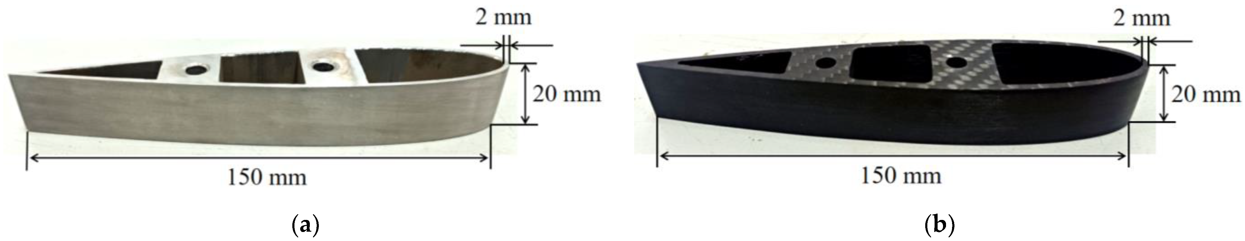
The blade segment sample with the airfoil of NACA0018 was used in the experiment, shown in
Figure 1. As shown in
Figure 1, the chord length of the blade segment is 150 mm; the thickness of the wall is 2 mm; and the length of the wing span is 20 mm. In the present study, the NACA0018 airfoil was selected because it has the characteristics of symmetry and a high power coefficient. Aluminum is widely used in icing research because of its isotropy and stable heat transfer characteristics. CFRP is commonly used in the skin of wind turbine blades because of its lower weight and higher strength [
13]. In this research, the blade segment sample was made of 6061 aluminum alloy and T300 CFRP. The material properties of experimental blades are shown in
Table 1.
2.2. Experimental System and Procedure
This paper built a reflux icing wind tunnel, as shown in
Figure 2. The icing wind tunnel was composed of the refrigeration system, the spray system, and the air duct. The cross-section size of the test chamber was 250 mm × 250 mm. The experimental conditions in the icing wind tunnel are listed in
Table 2. The nozzle was located in the center of the cross-section of the stable chamber. Water droplets were sprayed out of the nozzle and mixed with the cold airflow in the icing wind tunnel. They were then cooled into supercooled water droplets in the process of movement. In the test chamber, water droplets impact the blade surface and freeze; thus, the blade segment sample was fixed in the center of the cross-section of the test chamber, and the blocking area ratio was about 1.8%.
Before each icing test, the blade segment surface was cleaned with alcohol and dried by an air blower. The cleaned blade segment was fixed on the support of the icing wind tunnel test chamber, and the angle of attack of the experimental blade was 0°. The icing wind tunnel’s test temperature and wind speed were set through the control panel, and the precooling began. The electronic screen of the control panel displayed the temperature and wind speed in the test chamber in real time. When the temperature and wind speed reached the set value, the spray system installed in the stable chamber began to work. Then, the water droplets were mixed with cold air in the stable chamber to cool into supercooled water droplets, which collided with the blade segment after flowing into the test chamber. The ice shape on the blade surface was captured by a high-speed camera, model Phantomv5.1, and the acquisition interval was 2 min. Then the picture was imported into CAD software, and the contour of the ice was identified. When the time length of the icing test reached the set value, the spray system stopped working.
2.3. Experimental Scheme
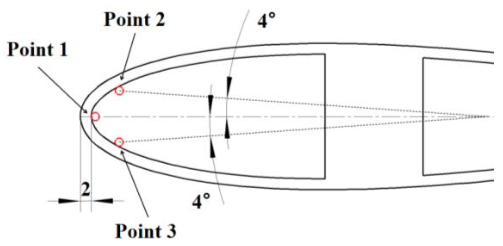
The temperature is one crucial factor that affects the ice type. The previous research results show three types of atmospheric ice under different temperature conditions: glaze, mixed, and rime ice. To explore the effects of temperature on the icing distribution, three kinds of ambient temperatures, −5 °C, −10 °C, and −15 °C, were selected. The time lengths of icing tests were 2 min, 4 min, and 6 min, respectively, in the present study. To be consistent with the experimental conditions of each test, such as the blade surface temperature, the blade segment was cooled down 5 min before the icing test. To acquire the variation of the surface temperature of the blade, a multichannel thermometer with T-type thermocouple, model KSA06A2R, was used to collect the surface temperature of the blade. The measuring points are shown in
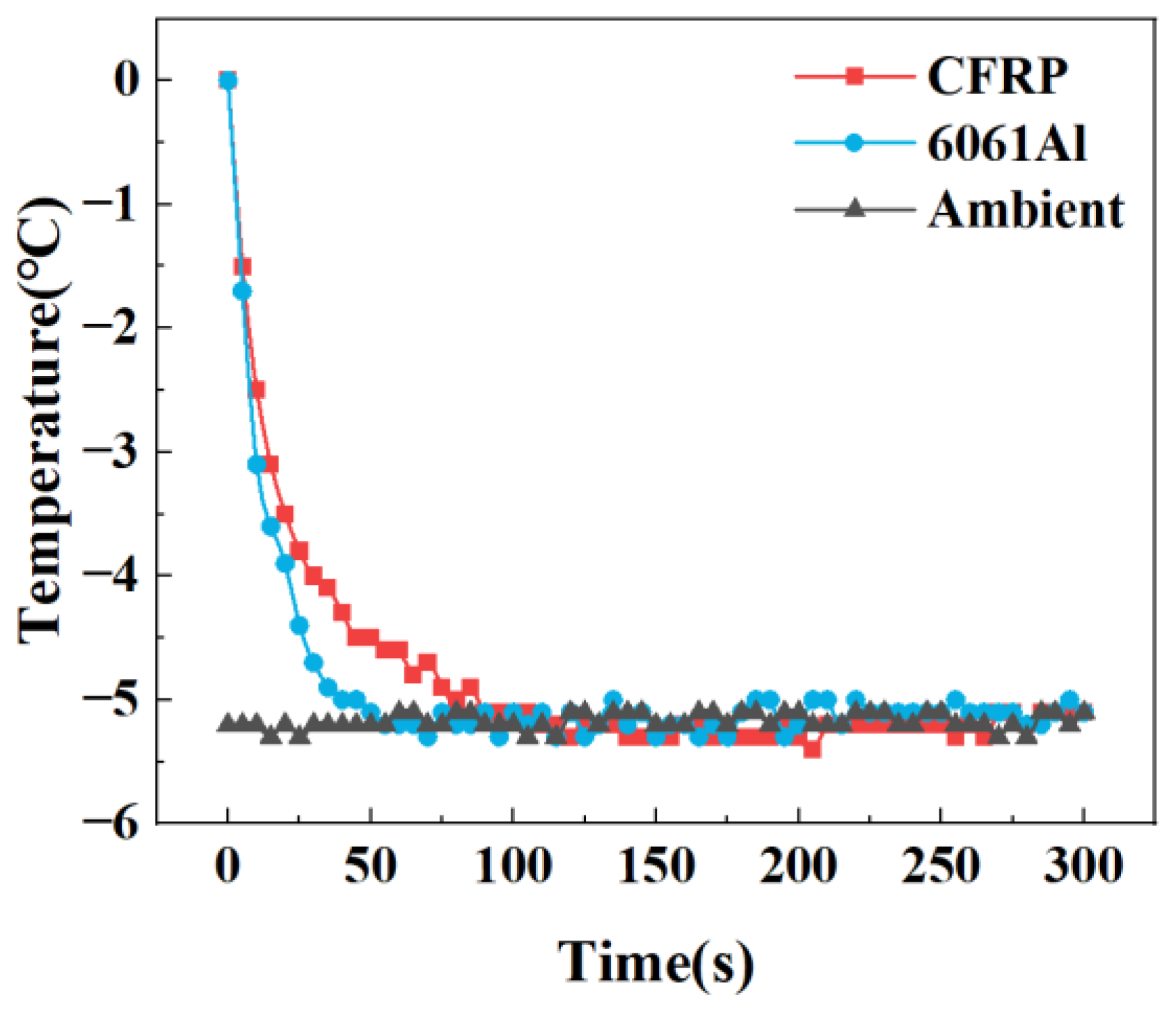
Figure 3. The thermometer displayed the blade surface temperature in real time. Under an ambient temperature of −5 °C and a wind speed of 10 m/s, the variation between the ambient temperature and blade surface is shown in
Figure 4. As shown in
Figure 2, when the cooling time was 50 s, the surface temperature of the 6061 aluminum alloy blade trended toward the ambient temperature. In contrast, when the cooling time was 100 s, the surface temperature of the CFRP blade trended toward the ambient temperature. Therefore, within a cooling time of 5 min, the surface temperature of 6061 aluminum alloy and the CFRP blade are the same. The experimental scheme is listed in
Table 3.
3. Evaluation Method
In order to quantitatively analyze the distribution of ice on the blade surface, the average thickness of ice parameter
H is defined in this paper.
Hi is the average thickness of ice in the normal direction of the airfoil profile within the corresponding region of the chord
xi − 1~
xi (
i = 1,2,3…), which is expressed as Equation (1).
where
Si is the ice area in the normal direction of the airfoil surface within the corresponding region of the chord
xi − 1~
xi (
i = 1,2,3…), and
Li is the curve length of the airfoil surface within the corresponding region of the chord
xi − 1~
xi (
i = 1,2,3…).
The schematic diagram of the parameters is expressed in Equation (1), as shown in
Figure 5. The x-axis is the chord of the airfoil in the figure, and the y-axis is the parallel line of the airfoil thickness.
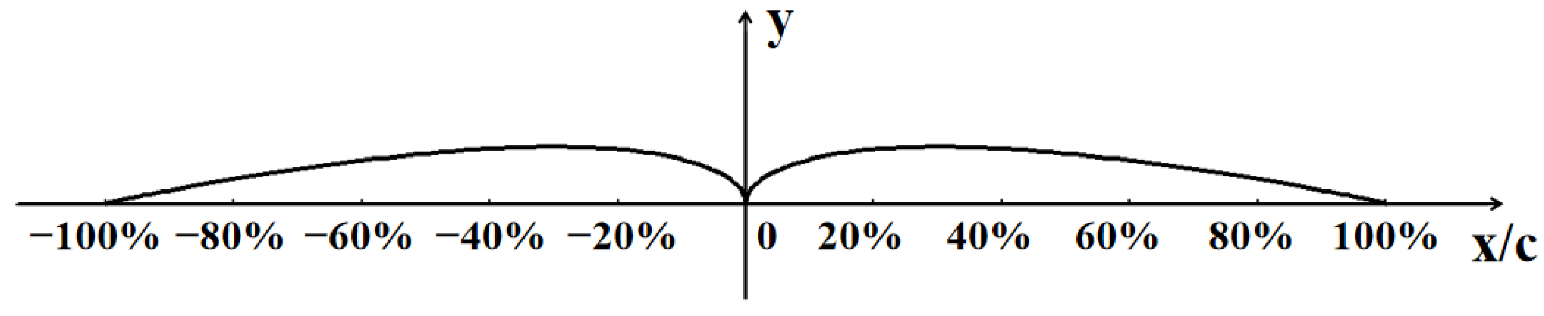
In this paper, the chord is dimensionless, and the relative position of the chord is marked to facilitate the analysis. The relative position of the chord is shown in
Figure 6. As shown in
Figure 6, the positive direction of the x-axis is the upper airfoil, the negative direction of the x-axis is the lower airfoil, c is the chord length of the airfoil, and the x/c is the relative position of the chord.
4. Results and Discussion
4.1. Distribution of Icing on the Blade Surface
The icing distribution of the blade surface under different conditions is shown in
Figure 7.
As shown in
Figure 7, the temperature and icing time significantly affect the shape and type of ice on the blade surface. When the temperatures are −5 °C, −10 °C, and −15 °C, the type of ice are glaze ice, mixed ice, and rime ice, respectively. With the decrease in temperature, the type of ice changes from glaze ice to rime ice, which is the same as the previous research results [
15]. When the temperature is −5 °C, icicles form on the lower airfoil surface of the CFRP blade, while there are none on the aluminum blade. The ice mainly concentrates on the blade’s leading edge from the figures. In the initial stage of icing, the thickness of the ice is thin, and the ice evenly distributes on the leading edge, which leads to a bit of damage to the aerodynamic profile of the blade. With the increase in the icing duration, the ice builds up layer by layer, the airfoil profile of the blade changes significantly, and the aerodynamic performance is destroyed.
4.2. Effect of Icing Duration on Icing Distribution
When the temperature is −10 °C, the wind speed is 10 m/s, and the icing time is 2 min, 4 min, and 6 min, respectively. The average thickness of ice on the blade surface is shown in
Figure 8. The average thickness of the ice accretion on the blade surface was tested five times under each experimental condition to confirm the accuracy of the test results.
As shown in
Figure 8, with the increase in icing time, the average ice thickness on the aluminum and CFRP blade surfaces increases. The ice thickness of the accretion on the aluminum blade is roughly the same as that of the CFRP blade. The ice thickness on the airfoil surface within the corresponding region of −1% ~ 1% of chord is significantly thicker than that of other areas. The upper and lower airfoil ice thickness decreases from the leading edge to the blade’s trailing edge. When the icing time length is 6 min, the thickness of the ice on the blade surface is the maximum. The maximum thickness of the ice on the aluminum blade is 8.8 mm, and that of the CFRP is 8.9 mm.
4.3. Effect of Temperature on Icing Distribution
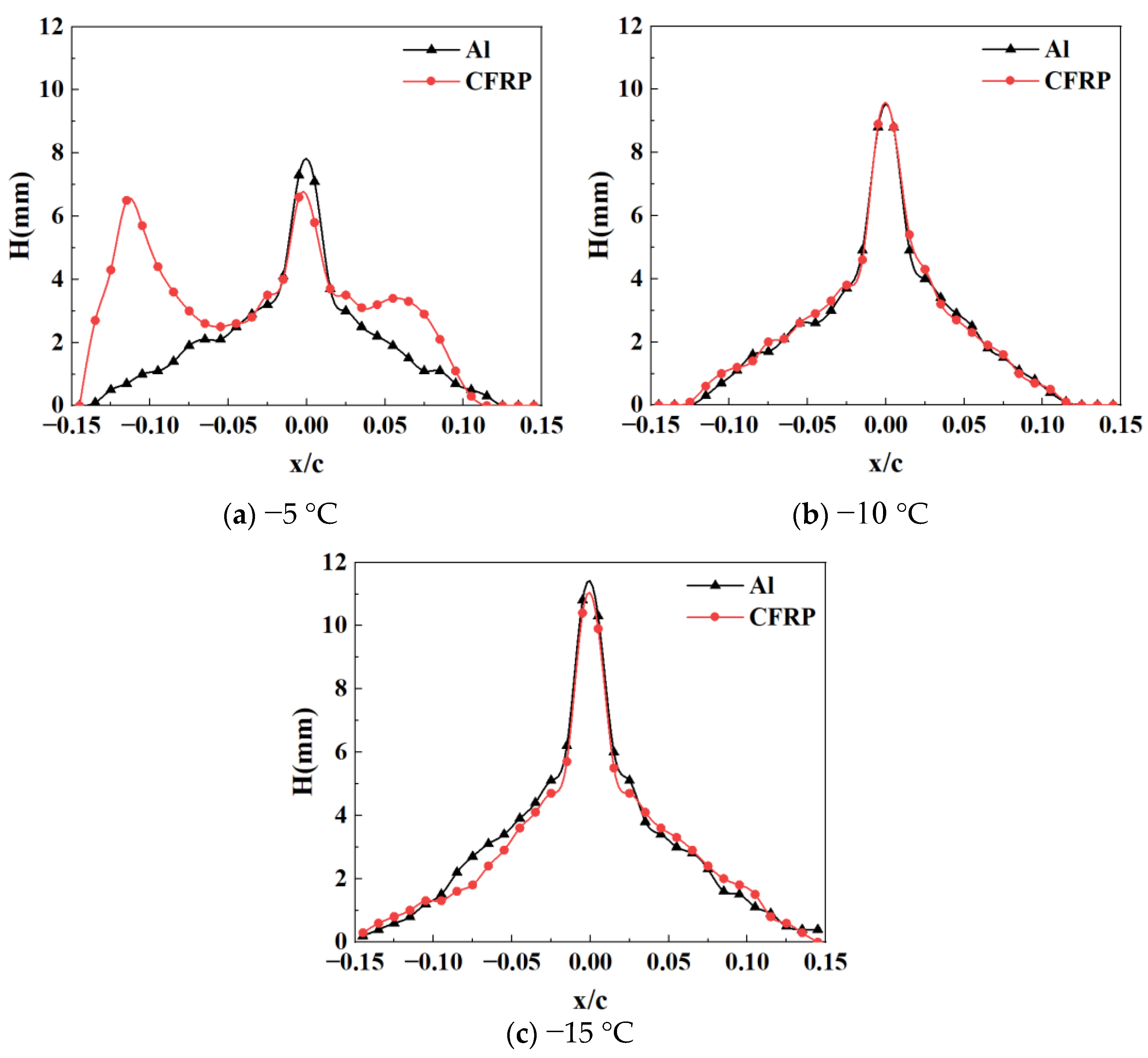
When the icing time is 6 min, the wind speed is 10 m/s, and the temperatures are −5 °C, −10 °C, and −15 °C, respectively. The average thickness of the ice on the blade surface is shown in
Figure 9.
As shown in
Figure 9, with the decrease in temperature, the average thickness of the ice on the surface of the aluminum and CFRP blades increases. The reason is that the freezing rate increases as the temperature decreases after supercooled droplets impact the blade surface. The energy transfer between the droplet, the blade, and the air is carried through heat conduction, thermal radiation, and convective heat transfer. At the temperature of −5 °C, the rate of energy transfer is slower, leading to droplet freezing on the blade surface for a long time. When the airflow force on the droplets is greater than the adhesive force between droplets and ice, the droplets will separate with the blade under the airflow action, which results in a thinner ice accretion on the blade surface. With the decrease in temperature, the rate of energy transfer between the droplets, the blade and the air increases, and the freezing time of the droplets shortens. The increase in the freezing rate of the droplets leads to the transition of the ice type from glaze ice to rime ice, and the ice thickness increases.
When the temperature is −5 °C, the ice accretion on the leading edge of the CFRP blade is thinner than the aluminum blade, and the icicle generates on the lower airfoil. While, at temperatures below −10 °C, the material of the blade has little effect on the icing distribution, and the distribution of ice accretion on the aluminum blade is roughly the same as that of the CFRP blade. This phenomenon is related to the thermal conductivity of materials. The thermal conductivity of CFRP is 10.5 W/(mK), while that of 6061 aluminum alloy is 167 W/(mK). Under the same conditions, the heat conduction rate of the CFRP blade is slower than the 6061 aluminum alloy blade, which leads to a longer time for droplets to freeze. The droplets flow and gather on the blade surface under airflow and gravity, resulting in a thinner ice accretion on the leading edge of the CFRP blade, the icicle generates on the lower airfoil of the CFRP blade. With the decrease in temperature, the energy transferred increases by droplets to the air through thermal radiation and convective heat transfer, and the freezing rate of the droplets increases. In this case, the effect of the thermal conductivity of the blade material on the freezing rate of the droplets decreases, the icing distribution of CFRP blades is roughly the same as that of aluminum blades, and there are no icicles generated on the lower airfoil of the CFRP blade. In addition, when the temperature is −15 °C, the thickness of the ice on the blade surface is the maximum. The maximum thickness of the ice on the aluminum blade is 10.8 mm, and that on the CFRP is 10.4 mm.
5. Conclusions
In this paper, experimental research on the effect of blade material on icing distribution was conducted. The conclusions are summarized as follows:
The icing time and ambient temperature are key factors that affect the icing distribution. When the icing time increases, the average thickness of ice on the blade surface increases, and the airfoil profile changes significantly. When the ambient temperature decreases, the average thickness of ice on the blade surface increases, and the ice type changes from glaze ice to rime ice.
The effect of blade material on the icing distribution is significantly affected by the ambient temperature. When the ambient temperature is −5 °C, the ice accretion on the leading edge of the CFRP blade is thinner than the aluminum blade, and icicles form on the lower airfoil. When the ambient temperature is below −10 °C, the material of the blade has little effect on the icing distribution, and the icing distribution of the aluminum blade is roughly the same as that of the CFRP blade.
Author Contributions
Conceptualization, W.L. and X.L.; methodology, C.W.; software, T.W.; validation, Z.M., Y.L. and W.L.; formal analysis, A.C.; resources, C.W.; data curation, H.S.; writing—original draft preparation, Y.L.; writing—review and editing, W.L.; supervision, X.L.; project administration, F.F.; funding acquisition, Y.L. All authors have read and agreed to the published version of the manuscript.
Funding
Research and Application of Key Technologies for High-Efficient Anti-icing and De-icing of Wind Turbine Blades’ (HNKJ22-H101) supported by Huaneng Group.
Institutional Review Board Statement
Not applicable.
Informed Consent Statement
Not applicable.
Data Availability Statement
Not applicable.
Conflicts of Interest
The authors declare no conflict of interest.
References
- GWEC: Global World Report-2021.
- Li, Y.; Shi, L.; Guo, W.-F.; Tagawa, K.; Zhao, B. Numerical simulation of icing effect on aerodynamic characteristics of a wind turbine blade. Therm. Sci. 2021, 25, 4643–4650. [Google Scholar] [CrossRef]
- Hu, L.; Zhu, X.; Hu, C.; Chen, J.; Du, Z. Wind turbines ice distribution and load response under icing conditions. Renew. Energy 2017, 113, 608–619. [Google Scholar] [CrossRef]
- Yan, L.; Ce, S.; Yu, J. Effect of liquid water content on blade icing shape of HAWT by numerical simulation. Therm. Sci. 2019, 23, 1637–1645. [Google Scholar]
- Shu, L.; Li, H.; Hu, Q.; Jiang, X.; Qiu, G.; McClure, G.; Yang, H. Study of ice accretion feature and power characteristics of wind turbines at natural icing environment. Cold Reg. Sci. Technol. 2018, 147, 45–54. [Google Scholar] [CrossRef]
- Li, Y.; Wang, S.; Sun, C.; Yi, X.; Guo, W.; Zhou, Z.; Feng, F. Icing distribution of rotating blade of horizontal axis wind turbine based on Quasi-3D numerical simulation. Therm. Sci. 2018, 22, 681–691. [Google Scholar] [CrossRef]
- Gao, L.; Hong, J. Wind turbine performance in natural icing environments: A field characterization. Cold Reg. Sci. Technol. 2021, 181, 103193. [Google Scholar] [CrossRef]
- Gao, L.; Hu, H. Wind turbine icing characteristics and icing-induced power losses to utility-scale wind turbines. Proc. Natl. Acad. Sci. USA 2021, 118, e2111461118. [Google Scholar] [CrossRef] [PubMed]
- Lamraoui, F.; Fortin, G.; Benoit, R.; Perron, J.; Masson, C. Atmospheric icing impact on wind turbine production. Cold Reg. Sci. Technol. 2014, 100, 36–49. [Google Scholar] [CrossRef]
- Guo, W.; Shen, H.; Li, Y.; Feng, F.; Tagawa, K. Wind tunnel tests of the rime icing characteristics of a straight-bladed vertical axis wind turbine. Renew. Energy 2021, 179, 116–132. [Google Scholar] [CrossRef]
- Gao, L.; Liu, Y.; Zhou, W.; Hu, H. An experimental study on the aerodynamic performance degradation of a wind turbine blade model induced by ice accretion process. Renew. Energy 2018, 133, 663–675. [Google Scholar] [CrossRef]
- Jin, Y.; Virk, S. Experimental study of ice accretion on S826 & S832 wind turbine blade profiles. Cold Reg. Sci. Technol. 2020, 169, 102913.1–102913.8. [Google Scholar]
- Mishnaevsky, L., Jr.; Branner, K.; Petersen, H.N.; Beauson, J.; McGugan, M.; Sørensen, B.F. Materials for wind turbine blades: An overview. Materials 2017, 10, 1285. [Google Scholar] [CrossRef] [PubMed] [Green Version]
- Shi, L.; Feng, F.; Guo, W.; Li, Y. Research and Development of a Small-Scale Icing Wind Tunnel Test System for Blade Airfoil Icing Characteristics. Int. J. Rotating Mach. 2021, 2021, 5598859. [Google Scholar] [CrossRef]
- ISO-12494; Atmospheric Icing of Structures. 2017. Available online: https://www.iso.org/obp/ui/#iso:std:iso:12494:ed-2:v1:en (accessed on 30 March 2023).
| Disclaimer/Publisher’s Note: The statements, opinions and data contained in all publications are solely those of the individual author(s) and contributor(s) and not of MDPI and/or the editor(s). MDPI and/or the editor(s) disclaim responsibility for any injury to people or property resulting from any ideas, methods, instructions or products referred to in the content. |
© 2023 by the authors. Licensee MDPI, Basel, Switzerland. This article is an open access article distributed under the terms and conditions of the Creative Commons Attribution (CC BY) license (https://creativecommons.org/licenses/by/4.0/).


