1. Introduction
In the past few decades, biodegradable metallic materials have served as one of the most promising strategies in regenerative medicine [
1]. Biodegradable metals have excel-lent mechanical properties, providing sufficient temporary support to resist the applied load, while the potential risk of long-term complications is effectively eliminated due to the progressive degradation of metals in the body [
2]. In addition, there is no need to per-form a second operation to remove the implant, since biodegradable bone implants in the form of rods, plates, screws and anchors should provide initial mechanical support and gradually dissolve in the physiological environment without causing infection, since they do not contain toxic components. Therefore, biodegradable metal implants are best fit for the stabilization of damaged bone tissue and directed bone healing. However, from the point of view of biological safety, there are strict requirements for the choice of material, such as a certain resorption rate, a balanced decrease in mechanical properties during bone tissue regeneration and the metabolism of resorption by-products in the body [
2].
Iron is the most abundant metal in the human body and is involved in a wide range of metabolic processes, such as oxygen transport, energy metabolism, enzyme function and DNA synthesis [
3]. In particular, it is known for its vital role in bone homeostasis, and iron deficiency causes bone disease and impairs bone mineralization [
4]. Despite its great potential for use in biodegradable orthopedic implants, its use is limited by its low corrosion rate in physiological environments [
5,
6].
The doping of iron alloys with copper makes it possible to increase the rate of resorption due to the formation of a Fe-Cu galvanic pair and to provide the antibacterial properties of the material implanted in the body [
7]. In addition, bicomponent Fe-Cu nanoparticles can suppress antibiotic resistance in bacteria [
7]. However, copper in large quantities can cause allergies to the implanted product [
8].
In order to allow bone ingrowth and promote a stable implant–bone interface, the surface of the artificial material must be bioactive to promote osteoconductivity through bone cell growth and biological apatite generation [
9,
10]. Hydroxyapatite (HA) with stoichiometry Ca
10(PO
4)
6(OH)
2 is widely used in the field of medical materials science as a bioactive bone substitute due to its excellent biocompatibility and chemical similarity with the mineral phase of human bone [
11,
12]. Hydroxyapatite has already been successfully added to iron [
13,
14] and magnesium [
15,
16] matrices to improve the bioactivity of these materials and use them in medicine.
According to the literature data, the Vickers hardness of iron is 0.6 GPa [
17], and that of copper is ~0.3 GPa, which is insufficient when the Fe–Cu composite material is used as a bone implant for the reconstruction of damaged bone tissues. Hydroxyapatite not only has excellent biocompatibility and a similar chemical and phase composition to bone tissue but also has a significantly higher hardness of ~5–6 GPa [
18,
19]. The addition of HA particles to the Fe-Cu composition will make it possible to obtain a composite material with higher strength characteristics.
However, in the case of iron implants, the problem of a low resorption rate remains relevant even in the case of alloying such materials with copper and hydroxyapatite. This problem can be solved by the formation of porous structures, using the 3D printing meth-od from a material based on iron powder alloyed with copper and hydroxyapatite to im-prove the biological properties of the final product. In addition, the manufacture of im-plants by this method allows us to avoid further mechanical processing of these products, which will positively affect the cost of the final medical device. However, for the formation of a metal product by this method, the addition of plasticizing binders is required.
The most commonly used controlled-release polymer in implant materials is ethylene vinyl acetate (EVA), which is a biocompatible, insoluble and non-toxic thermoplastic co-polymer of ethylene and vinyl acetate (VA). The content of VA in the EVA copolymer can vary from 0 to 40%. The EVA brand in this work was chosen after the following considerations. The properties of copolymers differ depending on the concentration of VA. Higher content results in increased polarity, adhesion, impact resistance, flexibility and compatibility of EVA with other polymers. At the same time, a higher VA content causes a decrease in the crystallinity, stiffness, softening and melting point of the copolymer [
20]. Based on these two competing factors, the prospective polymer is EVA EA28025 with a content of 28 wt.% VA [
21].
In the manufacture of composite materials, tall oil rosin is also widely used as a plasticizing component. Rosin acids, present in tall oil rosin, provide it with unique properties, such as solubility in many organic solvents, good compatibility with many polymeric materials, plasticity and relative adhesion. Tall oil rosin is characterized as a linear oligomer whose hydrogen bonds increase its mechanical strength, while maintaining elasticity [
22].
The aim of this work was to produce a porous biodegradable composite material based on iron, copper and hydroxyapatite powders that has antibacterial and bioactive properties, using the 3D printing method, with the addition of plasticizing binders in the form of polymers.
2. Materials and Methods
As a feedstock for the production of composites, we used a nanopowder with a nominal composition: Fe—90 wt.% and Cu—10 wt.% (Fe90-Cu10), obtained by the method of electric explosion of wire (EEW), with a diameter of d = 0.35 and d = 0.10 mm grades ST1 and M1, respectively, with the same length of 120 mm. The detailed EEW process and the schematic diagram of the installation are described in detail in References [
23,
24]. The production of nanopowder was carried out in an argon atmosphere, at a pressure of 3 atm., with a capacitor discharge of 2.4 μF and a voltage of 19 kV.
The obtained theoretical density of the powder Fe-Cu was 8 g/cm
3. The powder of stoichiometric hydroxyapatite Ca
10(PO
4)
6(OH)
2 (ISSCM SB RAS, Novosibirsk, Russia) [
25] was added to the metal part of the composite in the amount of 5 wt.%, at a density of 3.16 g/cm
3. The total density of the powder cermet mixture in these ratios was 7.76 g/cm
3.
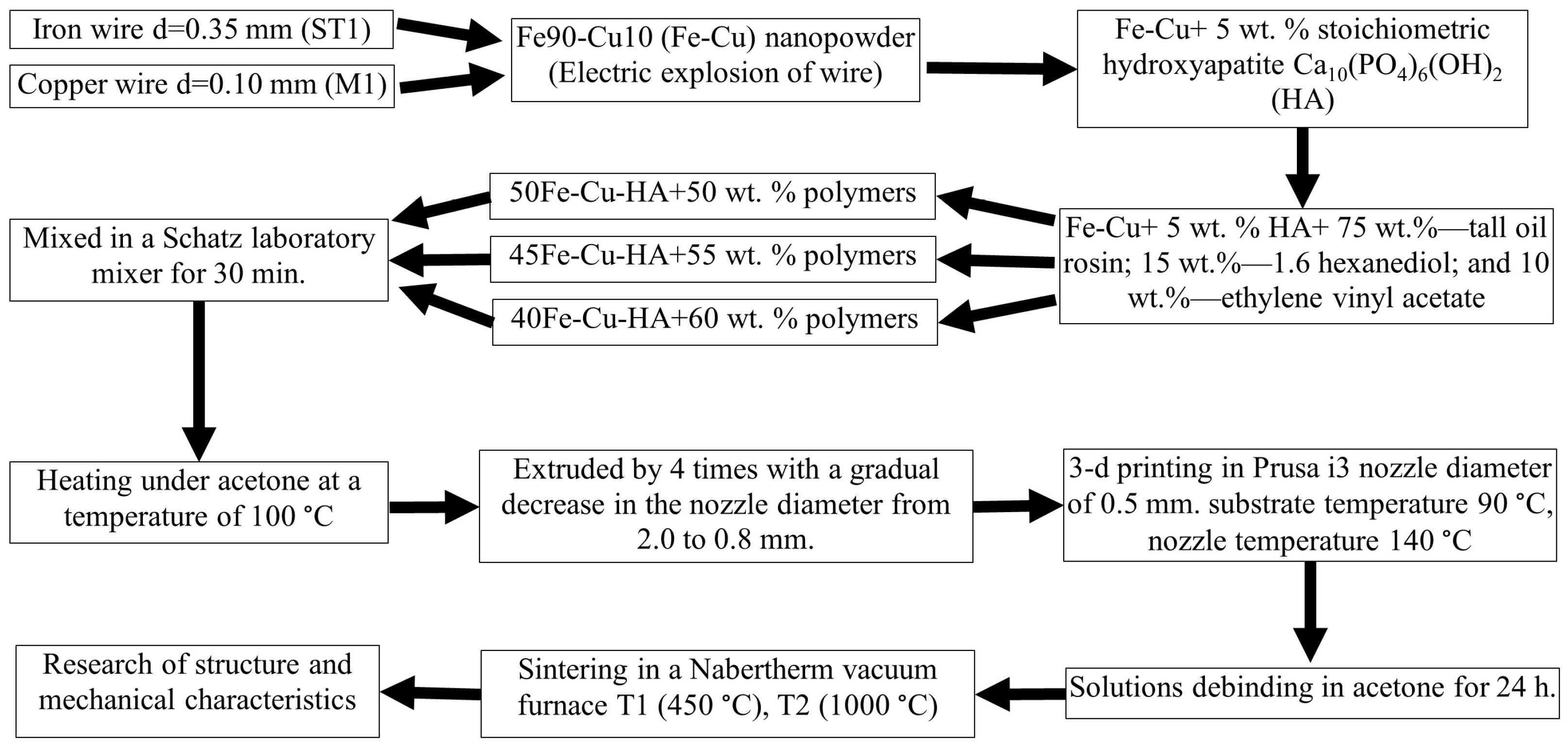
For the subsequent 3D printing, a polymer component was produced with the following nominal composition: 75 wt.%—tall oil rosin; 15 wt.%—1.6 hexanediol; and 10 wt.%—ethylene vinyl acetate.
The cermet and polymer parts were mixed in the following ratios: 50 to 50 (50Fe-Cu-HA), 45 to 55 (45Fe-Cu-HA) and 40 to 60 wt.% (40Fe-Cu-HA), respectively. For the uniform elements’ distribution, the resulting mixture was mixed in a Schatz laboratory mixer model C 2.0 “Turbula” (Vibrotechnik, St. Petersburg, Russia) for 30 min. To prevent further oxidation of the metal part of the powder, the polymer part was plasticized by heating under acetone at a temperature of 50 °C in an ultrasonic bath, Ferroplast VU-09-”Ya-FP”-03 (Ferroplast, Yaroslavl, Russia), which allowed us to limit the direct contact of the atmosphere with Fe and Cu particles.
The resulting material was passed through a screw extruder 4 times, with a gradual decrease in the nozzle diameter from 2.0 to 0.8 mm, which also increases the uniformity of the mixture’s composition. The desired shape for 3D printing was a cylinder with a diameter of 20 mm and a height of 2.5 mm. Printing was carried out on a 3D printer, Prusa i3 (Prusa Research, Prague, Czech Republic), with a modified wire feed system for printing powders with a polymer component. The following printing parameters were used in the manufacture of the “green part”: layer height, 0.25 mm; print speed, 60 mm/min; nozzle diameter, 0.5 mm; substrate temperature, 90 °C; and nozzle temperature, 140 °C.
To remove the polymer component of the workpiece, the product was subjected to solution debinding in acetone for 24 h. At this stage, tall oil rosin and 1.6 hexanediol were removed, while ethylene vinyl acetate is insoluble in acetone and allows us to keep the shape of the “green product” until the sintering of the cermet part.
Sintering was carried out in a Nabertherm vacuum furnace. Exposure at the temperature T1 (450 °C) ensures the removal of ethylene vinyl acetate from the final product, and at the temperature T2 (1000 °C), the particles of the ceramic–metal part are consolidated, and the product is finally formed. A general flowchart of the composite material samples is shown in
Figure 1.
Sample preparation was carried out by grinding on SiO2 abrasive with a gradual decrease in grain size from M180 to M1000 (GOST 6456-82). The polishing of the sample was carried out with a diamond suspension and abrasive 1/0 (GOST 25593-83). The sample was washed with ethanol to remove the remaining particles of a larger fraction at each stage of sample preparation. The microstructure was revealed by etching the sample surface for 5 s with a reagent of the following composition: 90 vol.%, H2O; and 10 vol.%, HNO3.
The study of the structure and the elemental analysis of materials were carried out using the following methods: optical microscopy (Altami MET 1MT (Altami, St. Petersburg, Russia)), scanning electron microscopy (Apreo S LoVac (Thermo Fisher Scientific, Waltham, USA) and LEO EVO 50 (Zeiss, Jena, Germany)) with attachments for energy-dispersive analysis and transmission electron microscopy (JEOL JEM-2100 (Tokyo Boeki Ltd., Tokyo, Japan)). The phase composition of the samples was identified by X-ray diffraction analysis (DRON 8N (Bourevestnik, St. Petersburg, Russia)). The processing of X-ray patterns was performed in the Match! 3 software, using the database COD from 18.07.2022. The phase-unit cell parameter was calculated in the FullProf additional software package. To determine the instrumental FWHM, the data from SiO2 specimen were used, the diffraction peaks of which were approximated using the Laplace function. The crystalline size and microstrains were calculated using the Williamson–Hall method. The distribution of Fe90-Cu10 powder particles was studied by sedimentation analysis on a CPS DC24000 UHR centrifuge (Analytik Ltd., Cambridge, UK).
The hardness tests of the materials were carried out by indentation, using an Affri DM8 microhardness tester with a Vickers diamond tetrahedral tip at various indentation loads in the range from 0.25 to 9.8 N for 10 s. For each composition, 3 samples were used. For each load cycle, 10 measurements were carried out in different parts of the sample, after which the results were averaged.
The Vickers hardness values were determined through the diagonal of the print obtained after the indenter was pressed in, according to Equation (1):
where
P is the applied load, N; and
d is the print diagonal, µm.
The measurement of porosity in sintered composites was carried out using the method of hydrostatic weighing in kerosene.
3. Results and Discussion
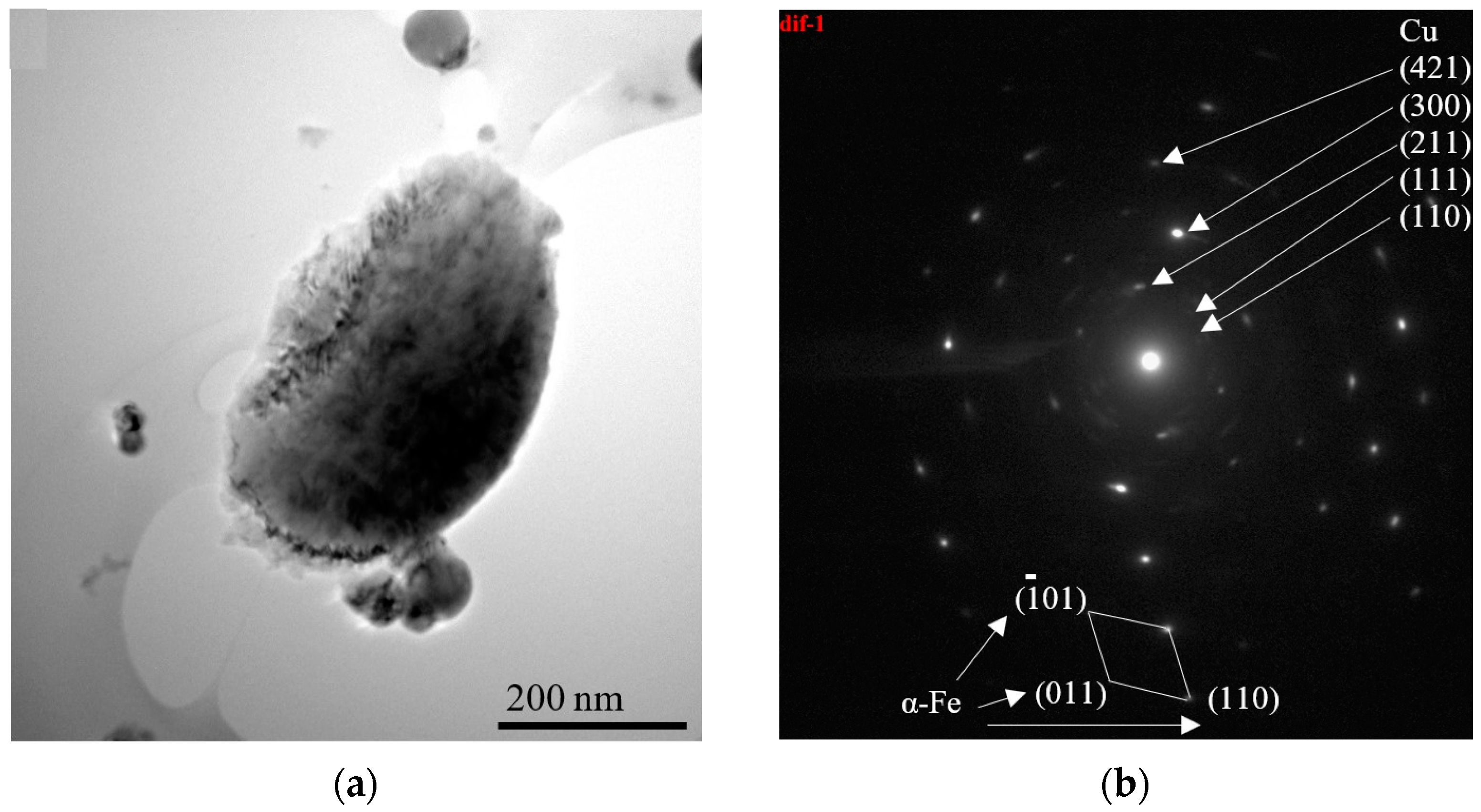
Figure 2 represents the TEM image and selected area electron diffraction with the Miller indices of the corresponding phases of the initial metal powder Fe90-Cu10. The selected area electron diffraction pattern indicates the presence of two phases in the powder particles. The first component of the picture is the point diffraction, for which the lattice parameters are close to the α-Fe phase. The second component is the ring-shaped diffraction of the Cu phase. The general diffraction pattern indicates that the particles of nanopowders consist of a matrix of the α-Fe phase, where Cu clusters are distributed, and the sizes do not exceed several tens of nanometers, since the ring shape of the diffraction pattern indicates multiple misorientations of the Cu lattice.
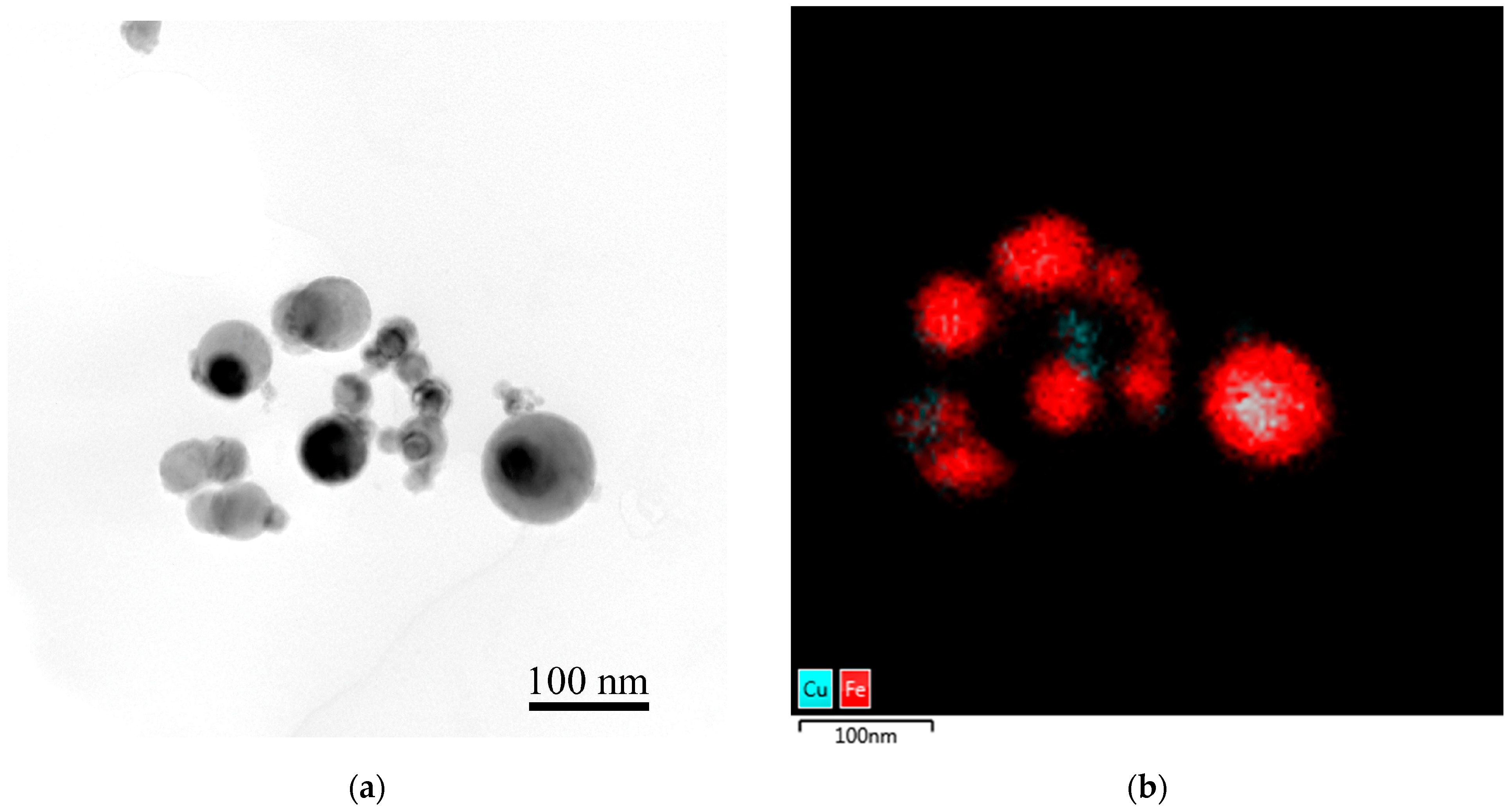
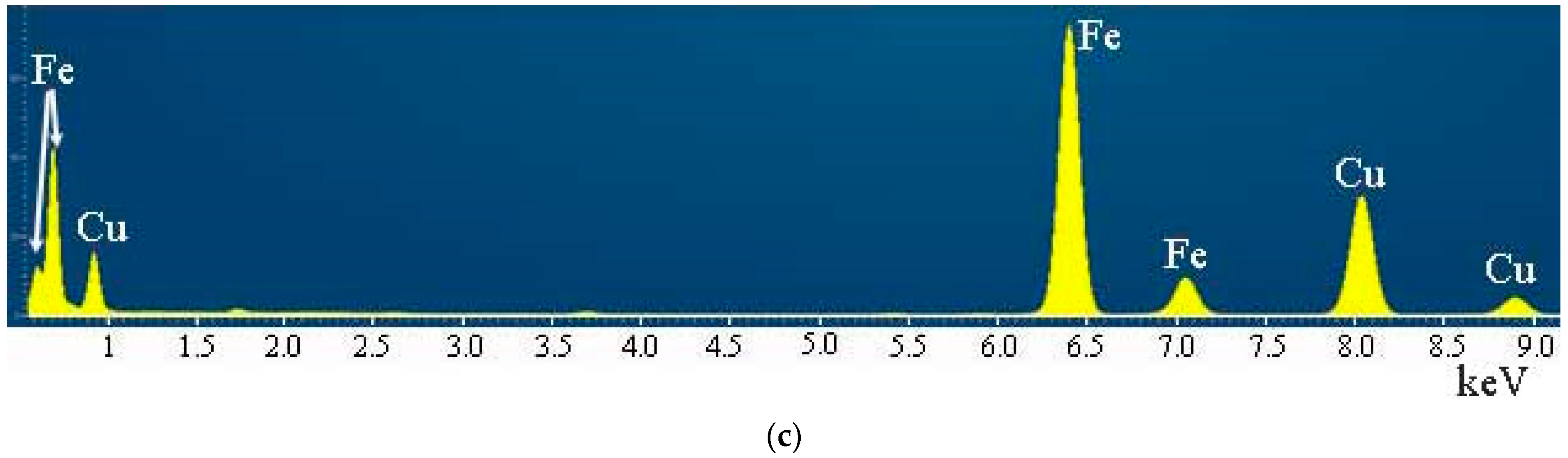
The EDS spectrum analysis showed (
Figure 3) that the composition of the powder is close to the nominal (Fe, 86.2 wt.%; Cu, 13.8 wt.%). Copper clusters are mainly located in the bulk of α-Fe phase particles, forming with it single metal particles.
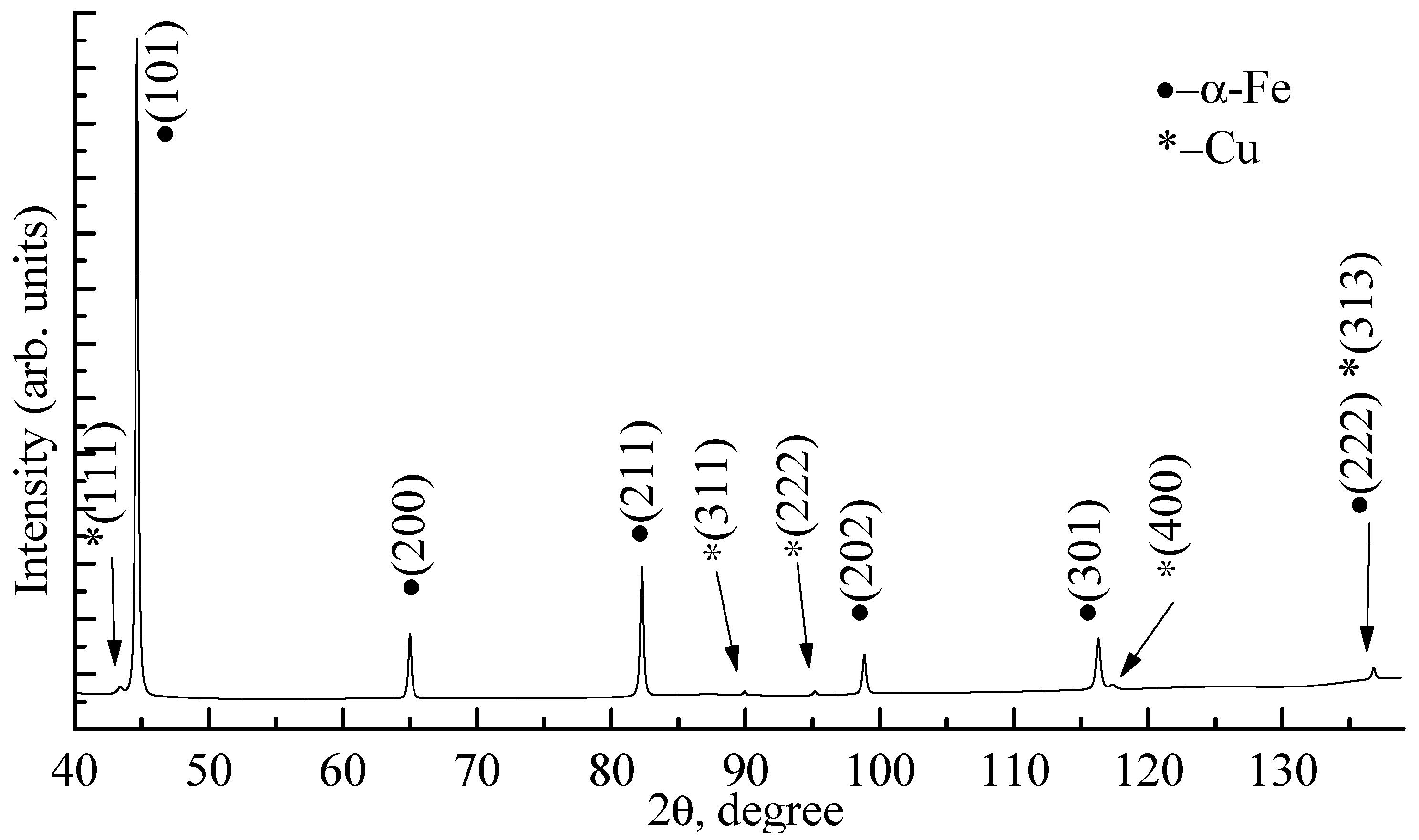
Figure 4 shows the X-ray diffraction pattern of the Fe90-Cu10 nanopowder obtained by the EEW.
The presence of two α-Fe and Cu phases was established in the metal powder, and the exact quantitative content of the second phase cannot be established due to the low intensity of reflections in relation to the first phase.
Table 1 represents the calculated lattice parameters of the α-Fe phase. The parameters of the Cu phase were not calculated due to the low intensity.
The calculated lattice parameter for the α-Fe phase coincides with the reference data within the measurement error. The powder has a high level of microstresses due to the method of production, which produces a metal with a high level of defects.
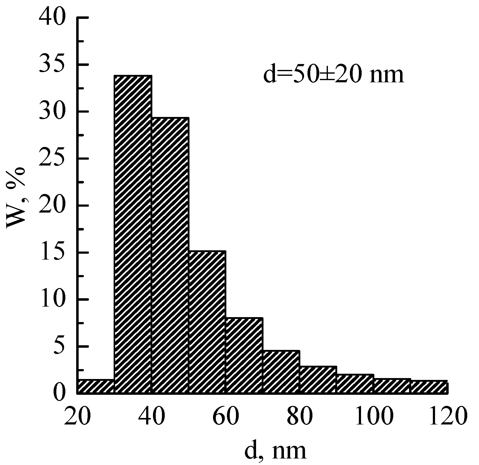
Figure 5 shows the particle distribution of the 90Fe-10Cu metal powder obtained by the EEW method. The distribution has a monomodal character, and the average particle size was 50 ± 20 nm. The powder contained particles larger than 100 nm, but their volume fraction did not exceed 5%. The data from X-ray analysis are comparable with the EEW method. The difference in crystallite size values is due to the presence of dislocations and atoms in the powder particles.
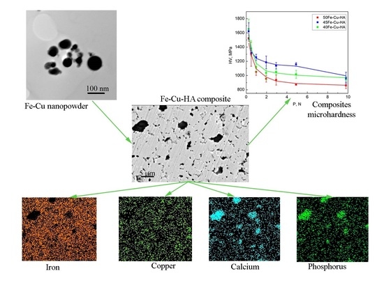
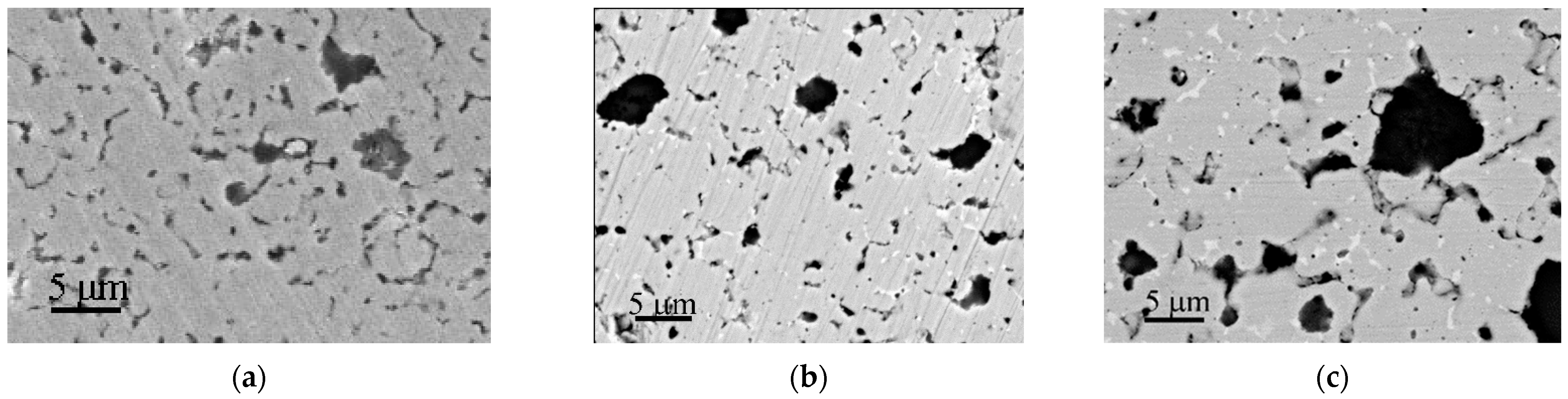
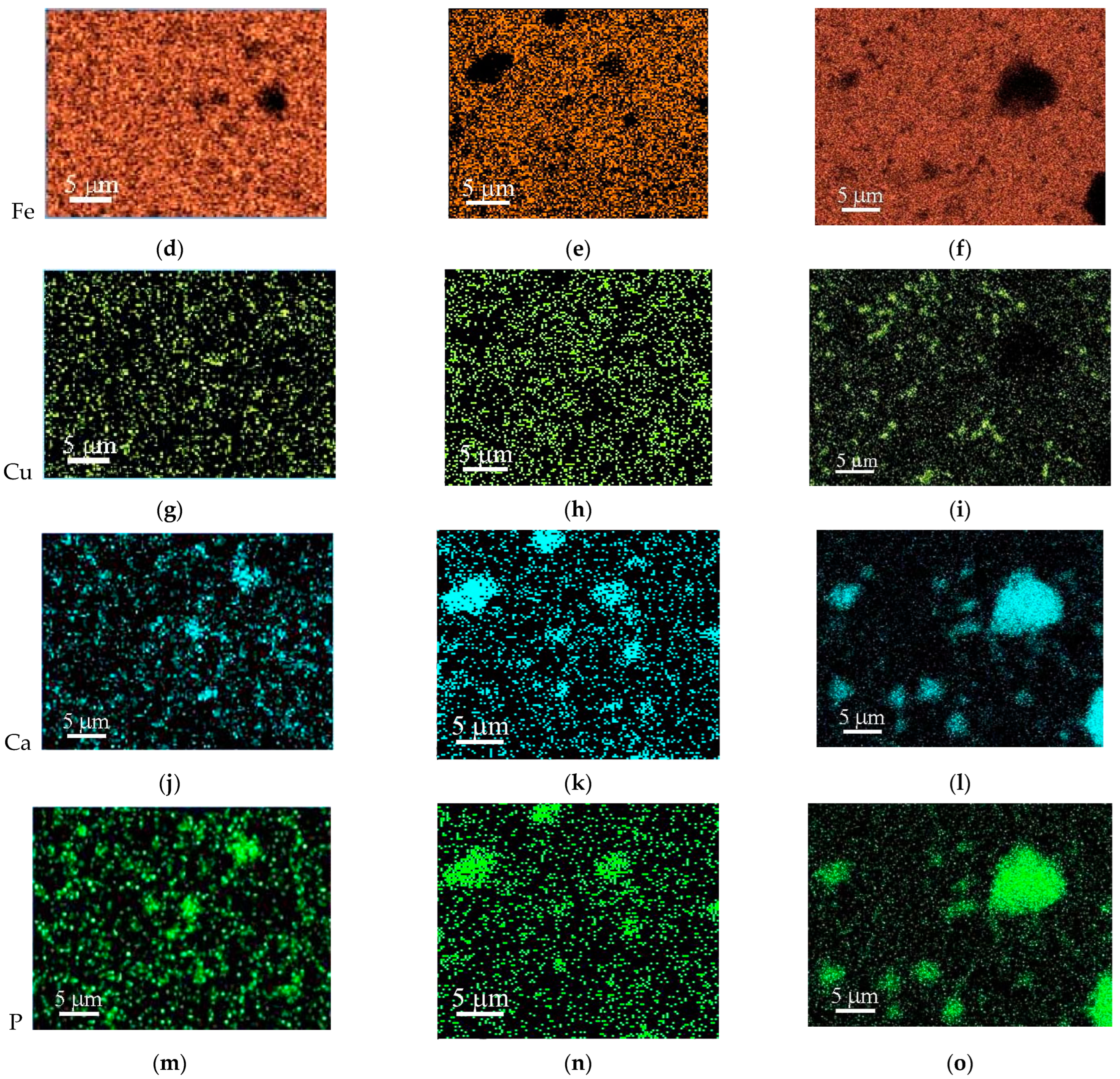
Figure 6 represents SEM images and maps of the elements’ distribution on the surface of samples produced with the addition of different amounts of Fe-Cu and HA powders (50, 45 and 40%). The surface of all samples is characterized by the presence of pores and HA particles. From the image and maps of the calcium and phosphorus distribution, it can be seen that, in the sample with 50% Fe-Cu-HA (
Figure 6a), there are small pores with an average size of 1.5 µm and a small number of HA particles with a larger size of 6.8 µm. In addition, copper is uniformly distributed on the surface of the composite in the form of small inclusions not exceeding 1 µm (
Figure 6b).
Figure 6 showed SEM images of the surface and maps of the elements (Fe, Cu, Ca and P) distribution of the produced samples: 50Fe-Cu-HA (a), 45Fe-Cu-HA (b) and 40Fe-Cu-HA (c).
Reducing the proportion of Fe-Cu and HA powders to 45% (
Figure 6b) leads to a more uniform distribution of HA powder particles and an increase in their amount. At the same time, the average pore size does not change with a decrease in the powder concentration to 45%, and the average size of HA particles decreases to 5.5 μm. The EDS maps show a uniform distribution of iron and copper, while calcium and phosphorus are concentrated in places where large HA particles are found. The surface of the sample with 40% Fe-Cu and HA (
Figure 6c) is characterized by large HA particles with an average size of 10 ± 5 µm and pores with an average size of 1.8 µm. The maximum amount of the polymer component in this sample led to less homogeneous mixing of the Fe-Cu-HA powder in the feedstock.
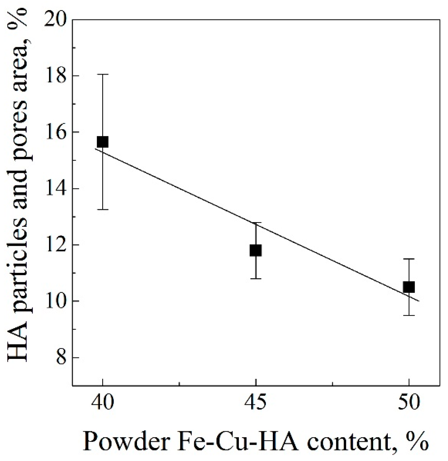
Figure 7 represents the dependence of the area occupied by HA particles and pores on the surface of composites vs. content of Fe-Cu-HA powder in the feedstock. With an increase in the Fe-Cu-HA powder content from 40 to 50% and a decrease in the polymer component of the feedstock, the total area occupied by HA particles and pores decreases from 16 to 10%. At the same time, as follows from the SEM results, the pattern of particles distribution in the composite varies depending on the amount of Fe-Cu-HA powder added. The hydrostatic weighing method showed that the open porosity of the composites does not depend on the amount of the polymer part (≈14%).
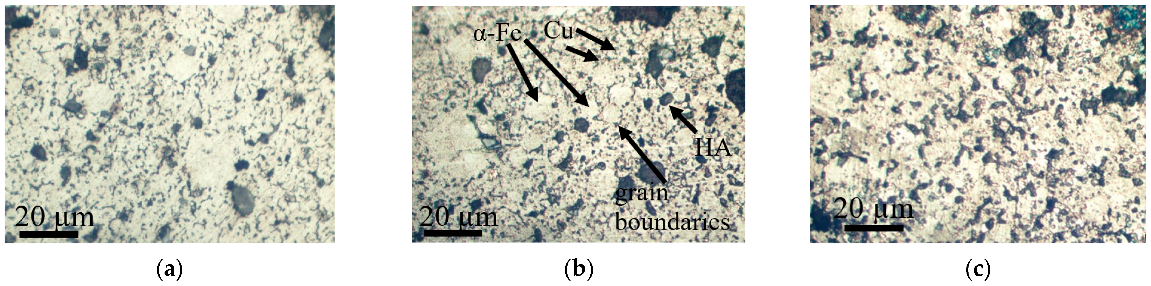
Optical images of the microstructure of composites after etching are shown in
Figure 8.
The structure of the samples after sintering is represented by the grains of α-Fe phase (light areas) with an average size of d = 10 ± 5 µm, with small inclusions of the Cu phase (orange areas), with an average size of d = 1 ± 0.5 µm, and some grains are separated from each other by wide grain boundaries (dark elongated areas). In addition, their fraction increases with the increasing of the polymer component before sintering.
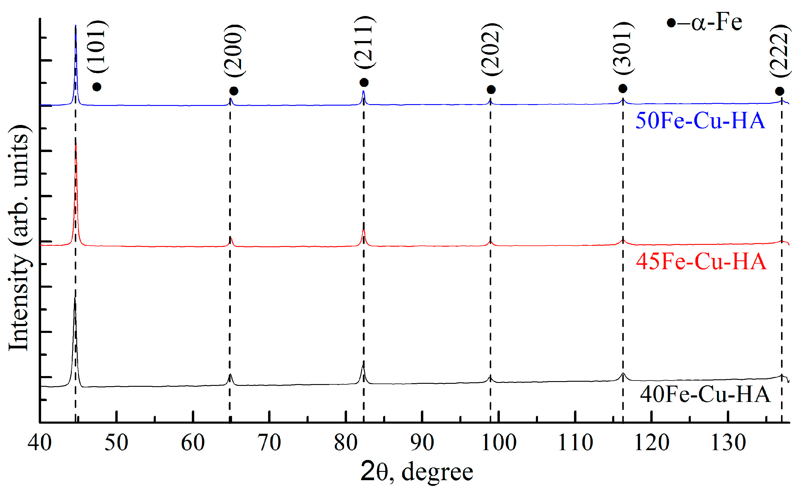
Figure 9 shows X-ray diffraction patterns of composites based on Fe-Cu-HA after sintering. As a result of the X-ray diffraction analysis, intense peaks of the α-Fe phase were found. The presence of copper and hydroxyapatite in any state was not identified by this method.
Table 2 represents the calculated lattice parameters of the main phase of iron, as well as the values of crystallite sizes and microstrains of the corresponding phases.
Powder consolidation leads to a decrease in microstrain values and an increase in crystallite size for the samples 50Fe-Cu-HA and 45Fe-Cu-HA. The 40Fe-Cu-Ha sample is characterized by the opposite change in values, which is due to the more defective structure of the α-Fe phase (
Table 2). The unit cell volume and the lattice parameter of the main phase in all composites correspond to the reference data within the measurement error. However, with a decrease in the Fe-Cu-HA powder concentration and an increase in the polymer component concentration in the composite after sintering, an increase in the microstrains and a decrease in the crystallite size occur (
Table 2). As mentioned above, the composites are characterized by the same value of open porosity; however, the values of the crystallite size and microstrains indicate an increase in the defectiveness of the structure, implying an increase in the amount or average size of closed pores with a change in the concentration of the polymer component of composites before consolidation.
Figure 10 and
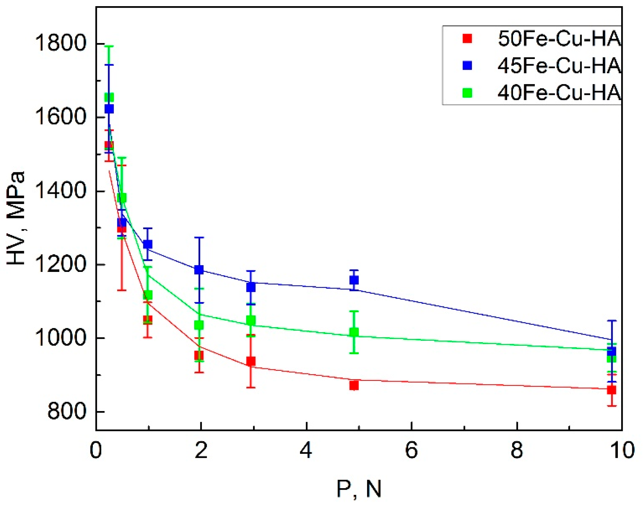
Table 3 represent the obtained dependences of average Vickers microhardness (HV) of composites on applied loads (P). Microhardness measurements were carried out on three materials of different composition. The microhardness of samples was measured by the Vickers indentation method for three samples in each composition. For each sample, 10 indentations were performed for each load. A multiply coefficient of 9.807 was used to convert Vickers hardness values from HV to MPa. The statistical analysis shows that the distribution of the random value of microhardness corresponds to the normal (Gaussian) law. The plot shows that with an increase in load from 0.25 to 10 N, the microhardness of all the samples changes from 1655 to 860 MPa.
The 50Fe-Cu-HA sample is characterized by the lowest microhardness; it decreases from 1525 to 860 MPa. This is due to the small amount of HA particles nonuniformly distributed in the sample bulk.
The 40Fe-Cu-HA sample is characterized by a higher value of microhardness. As the load is increased, the microhardness of the sample decreases from 1655 to 950 MPa. It should be noted that a great number of large HA particles separated from each other were observed in this sample, indicating a heterogeneous structure. At the same time, a high concentration of HA particles in the sample contributes to an increase in microhardness compared to the 50Fe-Cu-HA sample.
The highest microhardness values were observed during the 45Fe-Cu-HA samples’ tests. The microhardness of these samples decreased from 1625 to 965 MPa as the load was increased from 1 to 10 N. This result corresponds to the SEM results. A more uniform distribution of iron and HA particles in the samples contributed to an increase in the microhardness compared to the 50Fe-Cu-HA and 40Fe-Cu-HA samples.
In this case, the maximum scatter occurs in the lower range of loads and decreases as the applied load increases. At the same time, under such a load, the largest scatter of values is also visible, which indicates the inhomogeneity (HA particle distribution, porosity and feedstock component mixing) of the surface.
As a result of the research, the influence of the concentration of Fe-Cu-HA powder in the feedstock on the average Vickers hardness of the obtained composites was established.
In particular, the maximum values of microhardness under all loads were observed for the samples with the 45Fe-Cu-HA composition. Similar hardness values were obtained for other implant materials in the literature. In the reference [
26]. the vickers microhardness of β Ti-40Nb alloy for implants at the indentation load 4.9 N varies between 266 and 181 HV (2608 and 1775 MPa).
The microhardness of these bioresorbable composites is higher than that of magnesium alloys, but in acceptable ranges for medical devices [
27].
4. Conclusions
In the work, the bulk composite based on powders of the Fe-Cu system and hydroxyapatite was obtained using additive manufacturing based on the extrusion of materials.
Varying the amount of added Fe-Cu-HA powder from 50 to 40% led to the change in the morphology, phase and elemental compositions, as well as the microhardness of the resulting composites. The 45Fe-Cu-HA samples were characterized by the highest microhardness values, 1623-965 MPa at a load of 0.25-10 N, which is, on average, 26% higher than for the 50Fe-Cu-HA samples with the lowest microhardness values. This result is in a good agreement with the results obtained by the SEM method. In the 45Fe-Cu-HA composite, the most uniform distribution of iron and HA particles was observed, which contributed to an increase in its mechanical. Thus, a composite with a ratio of 45 to 55 wt.% of the cermet and polymer parts showed a higher microhardness compared to other composites and a more uniform distribution of antibacterial copper particles and bioactive hydroxyapatite particles, which can improve the biological properties of the material. In the future, a comparative study of the in vitro biological properties of three groups of composites is planned.
The study showed that the creation of a biocomposite material by 3D printing based on Fe-Cu bimetallic powder and hydroxyapatite is a promising approach for the manufacture of biodegradable implants for medical use.
Author Contributions
V.V.C., conceptualization, methodology, investigation, writing—original draft preparation, visualization, supervision, project administration, funding acquisition; N.A.L., methodology, investigation, writing—original draft, visualization; A.E.R., formal analysis, methodology, investigation, data curation, visualization; N.V.S., K.V.S. and L.Y.I., methodology, validation, formal analysis, investigation; M.A.K., formal analysis, validation, methodology, investigation, funding acquisition; N.E.T., I.A.G., A.A.M., S.O.K. and M.G.K., formal analysis, methodology, investigation, data curation. All authors have read and agreed to the published version of the manuscript.
Institutional Review Board Statement
Not applicable.
Informed Consent Statement
Not applicable.
Data Availability Statement
Not applicable.
Conflicts of Interest
The authors declare that they have no conflicts of interest to report regarding the present study.
References
- Kang, M.-H.; Cheon, K.-H.; Jo, K.-I.; Ahn, J.-H.; Kim, H.-E.; Jung, H.-D.; Jang, T.-S. An asymmetric surface coating strategy for improved corrosion resistance and vascular compatibility of magnesium alloy stents. Mater. Des. 2020, 196, 109182. [Google Scholar] [CrossRef]
- Cheon, K.-H.; Park, C.; Kang, M.-H.; Kang, I.-G.; Lee, M.-K.; Lee, H.; Kim, H.-E.; Jung, H.-D.; Jang, T.-S. Construction of tantalum/poly(ether imide) coatings on magnesium implants with both corrosion protection and osseointegration properties. Bioact. Mater. 2021, 6, 1189–1200. [Google Scholar] [CrossRef] [PubMed]
- Lin, W.; Zhang, H.; Zhang, W.; Qi, H.; Zhang, G.; Qian, J.; Li, X.; Qin, L.; Li, H.; Wang, X.; et al. In vivo degradation and endothelialization of an iron bioresorbable scaffold. Bioact. Mater. 2021, 6, 1028–1039. [Google Scholar] [CrossRef] [PubMed]
- Liao, Y.; Cao, H.; Xia, B.; Xiao, Q.; Liu, P.; Hu, G.; Zhang, C. Changes in Trace Element Contents and Morphology in Bones of Duck Exposed to Molybdenum or/and Cadmium. Biol. Trace Elem. Res. 2017, 175, 449–457. [Google Scholar] [CrossRef] [PubMed]
- Lin, W.; Qin, L.; Qi, H.; Zhang, D.; Zhang, G.; Gao, R.; Qiu, H.; Xia, Y.; Cao, P.; Wang, X.; et al. Long-term in vivo corrosion behavior, biocompatibility and bioresorption mechanism of a bioresorbable nitrided iron scaffold. Acta Biomater. 2017, 54, 454–468. [Google Scholar] [CrossRef]
- Lee, M.-K.; Lee, H.; Park, C.; Kang, I.-G.; Kim, J.; Kim, H.-E.; Jung, H.-D.; Jang, T.-S. Accelerated biodegradation of iron-based implants via tantalum-implanted surface nanostructures. Bioact. Mater. 2022, 9, 239–250. [Google Scholar] [CrossRef]
- Gutmanas, E.Y.; Gotman, I.; Sharipova, A.; Psakhie, S.G.; Swain, S.K.; Unger, R. Drug loaded biodegradable load-bearing nanocomposites for damaged bone repair. AIP Conf. Proc. 2017, 1882, 020025. [Google Scholar] [CrossRef]
- Kręcisz, B.; Kieć-Świerczyńska, M.; Chomiczewska-Skóra, D. Allergy to orthopedic metal implants—A prospective study. Int. J. Occup. Med. Environ. Health 2012, 25, 463–469. [Google Scholar] [CrossRef]
- Radulescu, D.-E.; Neacsu, I.A.; Grumezescu, A.-M.; Andronescu, E. Novel Trends into the Development of Natural Hydroxyapatite-Based Polymeric Composites for Bone Tissue Engineering. Polymers 2022, 14, 899. [Google Scholar] [CrossRef]
- Hou, X.; Zhang, L.; Zhou, Z.; Luo, X.; Wang, T.; Zhao, X.; Lu, B.; Chen, F.; Zheng, L. Calcium Phosphate-Based Biomaterials for Bone Repair. J. Funct. Biomater. 2022, 13, 187. [Google Scholar] [CrossRef]
- LeGeros, R.Z. Calcium Phosphate-Based Osteoinductive Materials. Chem. Rev. 2008, 108, 4742–4753. [Google Scholar] [CrossRef] [PubMed]
- Yamasaki, H.; Sakai, H. Osteogenic response to porous hydroxyapatite ceramics under the skin of dogs. Biomaterials 1992, 13, 308–312. [Google Scholar] [CrossRef] [PubMed]
- Lozhkomoev, A.S.; Lerner, M.I.; Pervikov, A.V.; Kazantsev, S.O.; Fomenko, A.N. Development of Fe/Cu and Fe/Ag Bimetallic Nanoparticles for Promising Biodegradable Materials with Antimicrobial Effect. Nanotechnol. Russ. 2018, 13, 18–25. [Google Scholar] [CrossRef]
- Ulum, M.; Arafat, A.; Noviana, D.; Yusop, A.; Nasution, A.; Kadir, M.A.; Hermawan, H. In vitro and in vivo degradation evaluation of novel iron-bioceramic composites for bone implant applications. Mater. Sci. Eng. C 2014, 36, 336–344. [Google Scholar] [CrossRef]
- Razavi, M.; Huang, Y. Effect of hydroxyapatite (HA) nanoparticles shape on biodegradation of Mg/HA nanocomposites processed by high shear solidification/equal channel angular extrusion route. Mater. Lett. 2020, 267, 127541. [Google Scholar] [CrossRef]
- Gu, X.; Zhou, W.; Zheng, Y.; Dong, L.; Xi, Y.; Chai, D. Microstructure, mechanical property, bio-corrosion and cytotoxicity evaluations of Mg/HA composites. Mater. Sci. Eng. C 2010, 30, 827–832. [Google Scholar] [CrossRef]
- Tobita, T.; Nakagawa, S.; Takeuchi, T.; Suzuki, M.; Ishikawa, N.; Chimi, Y.; Saitoh, Y.; Soneda, N.; Nishida, K.; Ishino, S.; et al. Effects of irradiation induced Cu clustering on Vickers hardness and electrical resistivity of Fe–Cu model alloys. J. Nucl. Mater. 2014, 452, 241–247. [Google Scholar] [CrossRef]
- Ramesh, S.; Tan, C.; Sopyan, I.; Hamdi, M.; Teng, W. Consolidation of nanocrystalline hydroxyapatite powder. Sci. Technol. Adv. Mater. 2007, 8, 124–130. [Google Scholar] [CrossRef]
- Zyman, Z.Z.; Tkachenko, M.V.; Polevodin, D.V. Preparation and characterization of biphasic calcium phosphate ceramics of desired composition. J. Mater. Sci. Mater. Med. 2008, 19, 2819–2825. [Google Scholar] [CrossRef]
- Genina, N.; Holländer, J.; Jukarainen, H.; Mäkilä, E.; Salonen, J.; Sandler, N. Ethylene vinyl acetate (EVA) as a new drug carrier for 3D printed medical drug delivery devices. Eur. J. Pharm. Sci. 2016, 90, 53–63. [Google Scholar] [CrossRef]
- Shelenkov, P.G.; Pantyukhov, P.V.; A Popov, A. Highly filled biocomposites based on ethylene-vinyl acetate copolymer and wood flour. IOP Conf. Ser. Mater. Sci. Eng. 2018, 369, 012043. [Google Scholar] [CrossRef]
- Aslamazova, T.R.; Lomovskoy, V.A.; Shorshina, A.S.; Zolotarevskii, V.I.; Kotenev, V.A.; Lomovskaya, N.Y. Temperature–Frequency Domains of Inelasticity in the Rosin–Copper and Rosin–Cellulose Composites. Russ. J. Phys. Chem. A 2022, 96, 222–229. [Google Scholar] [CrossRef]
- Pervikov, A.; Glazkova, E.; Lerner, M. Energy characteristics of the electrical explosion of two intertwined wires made of dissimilar metals. Phys. Plasmas 2018, 25, 070701. [Google Scholar] [CrossRef]
- Lerner, M.I.; Pervikov, A.V.; Glazkova, E.A.; Svarovskaya, N.V.; Lozhkomoev, A.S.; Psakhie, S.G. Structures of binary metallic nanoparticles produced by electrical explosion of two wires from immiscible elements. Powder Technol. 2016, 288, 371–378. [Google Scholar] [CrossRef]
- Chaikina, M.V.; Bulina, N.V.; Vinokurova, O.B.; Prosanov, I.Y.; Dudina, D.V. Interaction of calcium phosphates with calcium oxide or calcium hydroxide during the “soft” mechanochemical synthesis of hydroxyapatite. Ceram. Int. 2019, 45, 16927–16933. [Google Scholar] [CrossRef]
- Santos, R.F.M.; Ricci, V.P.; Afonso, C.R.M. Influence of Swaging on Microstructure, Elastic Modulus and Vickers Microhardness of β Ti-40Nb Alloy for Implants. J. Mater. Eng. Perform. 2021, 30, 3363–3369. [Google Scholar] [CrossRef]
- Elambharathi, B.; Kumar, S.D.; Dhanoop, V.; Dinakar, S.; Rajumar, S.; Sharma, S.; Kumar, V.; Li, C.; Eldin, E.M.T.; Wojciechowski, S. Novel insights on different treatment of magnesium alloys: A critical review. Heliyon 2022, 8, e11712. [Google Scholar] [CrossRef]
Figure 1.
General scheme of sample production.
Figure 1.
General scheme of sample production.
Figure 2.
TEM image of Fe90-Cu10 powder (a) with corresponding selected area electron diffraction (b).
Figure 2.
TEM image of Fe90-Cu10 powder (a) with corresponding selected area electron diffraction (b).
Figure 3.
TEM image of Fe90-Cu10 powder (a) with element distribution map (b) and overall EDS spectrum (c).
Figure 3.
TEM image of Fe90-Cu10 powder (a) with element distribution map (b) and overall EDS spectrum (c).
Figure 4.
X-ray diffraction pattern of the Fe90-Cu10 powder.
Figure 4.
X-ray diffraction pattern of the Fe90-Cu10 powder.
Figure 5.
Particle size distribution of 90Fe-10Cu powder.
Figure 5.
Particle size distribution of 90Fe-10Cu powder.
Figure 6.
SEM images (a–c) of the surface and maps of the elements (Fe, Cu, Ca, P) distribution (d–o) of the produced samples 50Fe-Cu-HA (a,d,g,j,m), 45Fe-Cu-HA (b,e,h,k,n), 40Fe-Cu-HA (c,f,i,l,o).
Figure 6.
SEM images (a–c) of the surface and maps of the elements (Fe, Cu, Ca, P) distribution (d–o) of the produced samples 50Fe-Cu-HA (a,d,g,j,m), 45Fe-Cu-HA (b,e,h,k,n), 40Fe-Cu-HA (c,f,i,l,o).
Figure 7.
Dependence of the area occupied by HA particles and pores on the surface of composites vs. content of Fe-Cu-HA powder in the feedstock.
Figure 7.
Dependence of the area occupied by HA particles and pores on the surface of composites vs. content of Fe-Cu-HA powder in the feedstock.
Figure 8.
Optical images of the microstructure of 50Fe-Cu-HA (a), 45Fe-Cu-HA (b) and 40Fe-Cu-HA (c) composite samples after etching.
Figure 8.
Optical images of the microstructure of 50Fe-Cu-HA (a), 45Fe-Cu-HA (b) and 40Fe-Cu-HA (c) composite samples after etching.
Figure 9.
X-ray diffraction patterns of composite samples with varying polymer fraction before sintering.
Figure 9.
X-ray diffraction patterns of composite samples with varying polymer fraction before sintering.
Figure 10.
Vickers microhardness vs. load applied to composite specimens.
Figure 10.
Vickers microhardness vs. load applied to composite specimens.
Table 1.
Calculated lattice parameter of phase in Fe90-Cu10 powder.
Table 1.
Calculated lattice parameter of phase in Fe90-Cu10 powder.
| Phase | Sample | Lattice Parameter a, Å | Unit Cell Volume, Å3 | Crystallite Size, nm | ε*, % |
|---|
| α-Fe | Reference data (COD 96-110-0109) | 2.868 | 23.590 | - | - |
| Fe90-Cu10 | 2.869 ± 0.001 | 23.62 ± 0.02 | 33 | 14.3 |
Table 2.
Calculated lattice parameters of α-Fe phase according to X-ray diffraction data for compo-sites.
Table 2.
Calculated lattice parameters of α-Fe phase according to X-ray diffraction data for compo-sites.
| Sample | Lattice Parameter a, Å | Unit Cell Volume, Å3 | Crystallite Size, nm | ε, % |
|---|
| Reference (COD 96-110-0109) | 2.868 | 23.590 | - | - |
| 50Fe-Cu-HA | 2.867 ± 0.001 | 23.58 ± 0.02 | 53 | 11.7 |
| 45Fe-Cu-HA | 2.868 ± 0.001 | 23.59 ± 0.02 | 45 | 13.6 |
| 40Fe-Cu-HA | 2.869 ± 0.001 | 23.60 ± 0.02 | 37 | 15.7 |
Table 3.
Vickers microhardness values for composites.
Table 3.
Vickers microhardness values for composites.
| P*, H | HV**, MPa |
|---|
| 50Fe-Cu-HA | 45Fe-Cu-HA | 40Fe-Cu-HA |
|---|
| 0.25 | 1525 ± 40 | 1625 ± 120 | 1655 ± 140 |
| 0.49 | 1300 ± 170 | 1315 ± 35 | 1380 ± 110 |
| 0.98 | 1050 ± 50 | 1255 ± 45 | 1120 ± 75 |
| 1.96 | 955 ± 50 | 1185 ± 90 | 1040 ± 100 |
| 2.94 | 940 ± 70 | 1140 ± 45 | 1050 ± 45 |
| 4.9 | 870 ± 7 | 1160 ± 30 | 1020 ± 55 |
| 9.8 | 860 ± 40 | 965 ± 85 | 950 ± 40 |
| Disclaimer/Publisher’s Note: The statements, opinions and data contained in all publications are solely those of the individual author(s) and contributor(s) and not of MDPI and/or the editor(s). MDPI and/or the editor(s) disclaim responsibility for any injury to people or property resulting from any ideas, methods, instructions or products referred to in the content. |
© 2023 by the authors. Licensee MDPI, Basel, Switzerland. This article is an open access article distributed under the terms and conditions of the Creative Commons Attribution (CC BY) license (https://creativecommons.org/licenses/by/4.0/).

 ,
, 


