Effects of Organic Additives on Alkaline Non-Cyanide Zinc Electroplating


1
Department of Materials Science and Metallurgical Engineering, Kyungpook National University, Daegu 41566, Republic of Korea
2
R&D Center, ILSUNG Plating Co., Ltd., Daegu 42697, Republic of Korea
*
Author to whom correspondence should be addressed.
Coatings 2023, 13(4), 781; https://doi.org/10.3390/coatings13040781
Submission received: 15 March 2023
/
Revised: 10 April 2023
/
Accepted: 14 April 2023
/
Published: 18 April 2023
(This article belongs to the Section Corrosion, Wear and Erosion)
Abstract
:We investigated the effects and interactions of the organic additives Polyquaternium-2 (PUB) and 1-benzyl pyridinium-3-carboxylate (BPC) in alkaline non-cyanide zinc electroplating. As PUB and BPC were added, the cathode potential of the polarization curve shifted in the negative direction at the same current density that occurred in the electrochemical experiment, and as confirmed by a scanning electron microscopy, the particles on the plating surface in the zinc deposits became finer, and the grain size decreased. Moreover, strong (101) and (002) peaks appeared in the X-ray diffraction pattern when no additive was added. However, as PUB and BPC were added, the intensity of the two peaks decreased, and an increase in the intensity of the (100) peak changed to a crystallographic orientation. With the addition of PUB and BPC, the gloss and whiteness gradually increased, and the surface roughness decreased. Finally, the throwing power tended to increase as PUB and BPC were added.
1. Introduction
Steel is one of the preferred materials for constructing and manufacturing various structures because of its strength, ductility, and low cost. However, it has a major disadvantage of corrosion when it is exposed to oxygen and moisture. To prevent corrosion, structural steel must be coated with a less corrosive metal, paint, or enamel. Zinc provides good protection for steel because of its relatively low corrosion rate [1].
The most common industrial methods for zinc coating of steel are hot-dip galvanizing and electro-galvanizing. Hot-dipping always involves alloying on some surfaces by diffusion. The deposition thickness is more evenly controlled by hot-dip galvanizing than by electro-galvanizing. Electro-galvanizing is performed at a lower temperature than hot-dip galvanizing. Galvanizing does not affect the mechanical properties of the steel substrate. It can also produce a uniform, bright, and adherent coating on steel. Electro-galvanizing is often preferred over hot-dip galvanizing when a decorative finish is required [1,2].
Cyanide-based galvanizing baths have dominated the electro-galvanizing industry for decades because of their efficiency and ease of use. However, their use has declined over time because of cyanide toxicity and the increasingly stringent environmental regulations. Electro-galvanizing technology has shifted to using less toxic acid zinc and alkaline zincate (non-cyanide) baths [1,3].
Alkaline non-cyanide galvanizing baths solve the toxicity problems of cyanide-based galvanizing baths and the inherent corrosiveness of acidic baths to the equipment used while exhibiting adequate galvanizing adhesion. However, because there is no effect of the complexation of cyanide, unattached precipitates in powder form are generated in the alkaline non-cyanide galvanizing bath. Therefore, plating additives are required in alkaline non-cyanide galvanizing baths to produce smooth and adherent zinc plating [1,2,3,4,5].
Numerous research advances have been made in the field of reaction kinetics of metal plating processes, and previous studies have shown that organic additives can be used to improve the brightness, smoothness, residual stress, particle size, and metallic impurities in zinc electroplating. However, many aspects of the mechanism of action of additives used as levelers (carriers) or brighteners remain poorly understood. In addition, because there are numerous additives that are used in electrodeposition, it is not easy to classify them. In general, the two main types of additives used in alkaline non-cyanide zinc electroplating are levelers (carriers) and brighteners [6,7].
The main function of a leveler was defined by Thomas [8] as the ability of an electroplating solution to produce deposits that are relatively thick on small recess areas and relatively thin on small protrusions as the depth or height of the small surface irregularities ultimately decreases. A distinction must be made between “geometric leveling”, which is produced by a uniform current distribution, and “true leveling”, which can occur in the presence of organic additives because of a higher current density on recess areas than on protrusions of the plating layer surface [7,9]. Levelers are organic additives that are commonly used to improve the throwing power, which provides a uniform coating and a smooth electrodeposition surface. A leveler effectively suppresses the electrode reaction, particularly by blocking the active site while being adsorbed onto the surface of the cathode. Thus, the further reduction of zinc ions is limited. This inhibitory effect can contribute significantly to forming finer particles. One of the commonly used levelers for alkaline zinc electroplating is poly[bis(2-chloroethyl) ether-alt-1,3-bis[3-(dimethylamino)propyl]urea] (Polyquaternium-2 or Rugaban P), which belongs to the family of polycationic polymers. Zinc ions and brighteners can be consumed quickly during the plating process, but levelers, which are high-molecular-weight compounds, are difficult to deplete [6].
Gloss is achieved by the ability of an electroplating solution to produce fine deposits that are composed of crystallites with an oriented grain structure smaller than the wavelength of visible light (i.e., smaller than 0.4 µm [10,11]). A small particle size is a necessary but not sufficient condition for brightness. Likewise, not all fine precipitates are bright. Brightness depends on the extent to which the morphological components of the electrodeposited surface lie in the same plane [7]. Brighteners are essential in controlling the brightness, smoothness, reflectance, and corrosion resistance of the precipitate surface. Small amounts of brighteners, such as carbonyl compounds, quaternary ammonium compounds (QACs), and aromatic or heterocyclic aldehyde compounds, are usually added to the plating bath to modify the crystal growth and control the rate of deposition during the electroplating process. Typical brighteners for modern alkaline non-cyanide zinc electrolytes include the following quaternary ammonium compounds (QACs): 1-benzyl-3-carboxypyridinium chloride (3NCP), 1-propyl-3-carboxypyridinium bromide (P3N), and 1-benzyl-4-carboxypyridinium chloride (B4N). The surface brightness obtained is related to forming a dimer species of QACs that can effectively inhibit the growth of zinc dendrites. Of the typical brighteners, 3NCP is an excellent brightening agent when combined with 1-benzyl pyridinium-3-carboxylate (BPC) or Na-N-benzyl nicotinate, which is a carboxylate form of 3NCP [6].
Some additives, such as thiourea in Watts-type nickel electroplating baths, can simultaneously function as levelers and brighteners. However, levelers and brighteners are often combined to achieve both tasks. The specific action of particular agents in a particular plating bath is one of the most elusive properties. Slight changes in the structure of the polish can ruin the polishing ability. Therefore, there is little opportunity to use the same agent in different plating baths [7].
The composition of the plating bath is one of the most important factors controlling the plating appearance, desired surface properties, and efficiency of the plating bath. Therefore, tracking and replenishing the additive content in the plating bath is necessary to maintain the plating bath conditions and the quality of the electrodeposition according to the conditions. Additive replenishment is usually conducted based on plating ampere-hour calculations or Hull cell analysis, which qualitatively approximates the amount of additives remaining in the plating bath. An inadequate supply of additives can hinder effective plating. Conversely, an excess of additives, particularly brighteners, can produce brittle and porous coatings, particularly in the low-current-density region, reducing the plating thickness and delaying blistering. Therefore, the consumption rate of additives and the corresponding replenishment schedule are significant for accurately controlling the plating bath [6].
Numerous organic additives were used in alkaline non-cyanide zinc electroplating baths; however, the effect of each organic additive on zinc electroplating has not yet been properly studied. Therefore, in this study, we evaluated the changes in the organic additive content in an alkaline non-cyanide zinc electroplating bath and the effects on the corresponding microstructure and electrodeposition properties. An alkaline non-cyanide zinc electroplating solution was prepared using Polyquaternium-2 (PUB) and BPC as a leveler and brightener, respectively. Their individual and synergistic effects on electrochemical analysis, surface morphology change, X-ray diffraction (XRD) pattern, grain size, gloss, whiteness, surface roughness, and throwing power were all investigated to characterize the contributions of the organic additives.
2. Materials and Methods
2.1. Materials
The electrolyte solution used in this study contained 9.6 g/L of zinc obtained by dissolving 12 g/L of zinc oxide (ZnO, Extra Pure, Duksan, Ansan, Republic of Korea) and 130 g/L of NaOH (Extra Pure, Duksan, Ansan, Republic of Korea). The organic additives were a polymer of N,N′-bis[3-(dimethylamino)propyl]urea and 1,1′-oxybis[2-chloroethane] at a concentration of 20 vol.% (PUB(Polyquaternium-2), CAS No. 68555-36-2, Wuhan Bright Chemical, Wuhan, China), and 1-benzylpyridinium-3-carboxylate (BPC, CAS No. 15990-43-9, Wuhan Bright Chemical, Wuhan, China) at a concentration of 3 vol.%. All solutions were prepared using deionized water. Table 1 shows the properties of organic additives used in this study.
2.2. Methods
2.2.1. Electrochemical Experiments
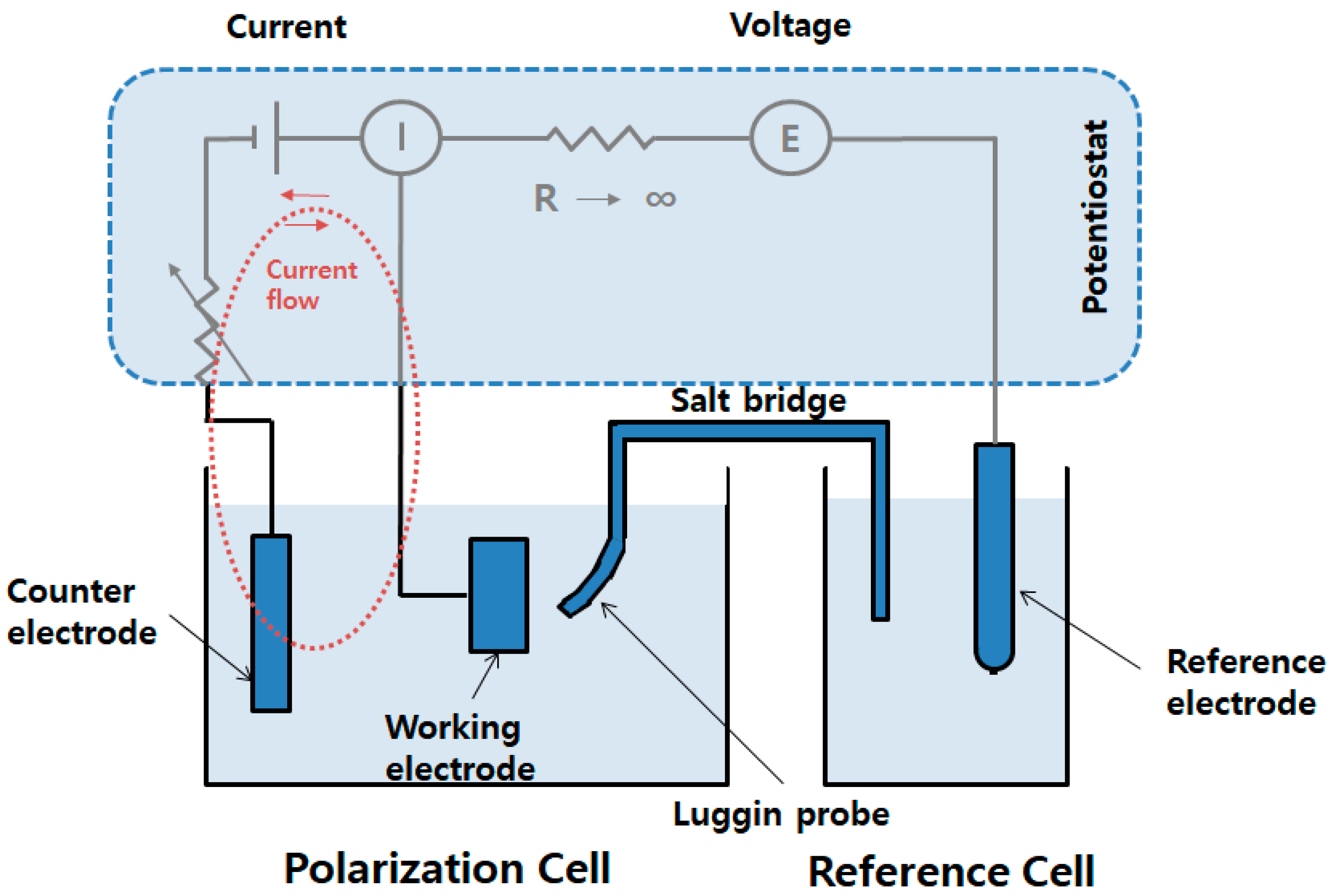
The electrochemical experiment used the three-electrode method. A platinum (Pt) mesh electrode was used as a counter electrode, and a saturated calomel electrode (SCE) was used as a reference electrode. An iron (Fe) cathode specimen (25 × 40 mm2) was used as the working electrode, and 500 mL of the electrolyte solution was used each time. Electrochemical polarization curves were obtained using potentiostat/galvanostat (HA-151B, Hokuto Denko, Atsugi, Japan). Figure 1 shows a schematic of the polarization process used in this experiment.
The plated zinc (Zn) precipitate from the electrochemical experiment was dissolved using nitric acid. The Zn content was quantitatively analyzed via atomic absorption spectrometry (AAS, iCE 3000 Series, Thermo Fisher Scientific, Waltham, MA, USA). The current efficiency for zinc plating was calculated by comparing the theoretical electrodeposited amount and the deposited Zn amount. The partial current densities for Zn and hydrogen (H2) were calculated by multiplying each current efficiency by the total current density. The current efficiency for hydrogen evolution was calculated by subtracting the zinc plating current efficiency from 100%.
2.2.2. Hull Cell Experiment
In the Hull cell experiment, a 500 mL-long Hull cell tank (LHC-4, Jungdo, Gimpo, Republic of Korea) was used together with a Zn anode for the Hull cell (63 × 64 × 3 (t)mm, Jungdo, Gimpo, Republic of Korea). An Fe cathode for the long Hull cell (200 × 65 × 0.3 (t)mm, Jungdo, Gimpo, Republic of Korea) was used as the cathode specimen.
The morphology of the Zn surface was investigated using a scanning electron microscope (SEM, PW-100-017, Phenom World, Eindhoven, The Netherlands). X-ray diffraction experiments were performed using 2θ scans between 20° and 90° with an X-ray diffractometer (Empyrean, Malvern Panalytical, Almelo, The Netherlands). The grain sizes of the Zn deposits were obtained using the well-known Scherrer equation [12]. The crystallite size L was calculated as follows:
where λ is the X-ray wavelength (nm), K is a shape factor that varies with the shape of the crystallite from 0.62 to 2.08 but is usually taken as 0.9, β is the full width at half maximum (FWHM), and θ is calculated using the diffraction angle.
The external gloss of the coating layer was measured using a glossmeter (4563(micro-TRI-gloss/20° 60° 85°), BYK Gardner, Wesel, Germany) that integrates 20°, 60°, and 85° measurements into one glossmeter to measure high, medium, and low gloss (measurement range: 0 to 2000 GU). The whiteness of the appearance of the coating layer was measured using a spectrophotometer (CM-2500d, Konica Minolta, Chiyoda, Japan). The surface roughness of the appearance of the plating layer was measured using a confocal laser scanning microscope (LSM700, Carl Zeiss, Oberkochen, Germany).
2.2.3. Throwing Power Experiment
A 1000 mL Haring–Blum cell (HBC3, Jungdo, Gimpo, Republic of Korea) was used with a Zn anode for the Hull cell. An Fe cathode for a Haring cell (65 × 80 × 0.3 (t)mm, Jungdo, Gimpo, Republic of Korea) was used as a cathode specimen. The throwing power experiment was conducted after fixing a cathode specimen at each end of the Haring cell and one anode in the middle. The distance ratio from the anode to the cathode at both ends was 5:1. The throwing power (TP (%)) was calculated using Field’s formula [13]:
where P is the current distribution ratio from the anode to both cathodes, which is the reciprocal of the distance (b/a) and M is the metal precipitation ratio of both cathode specimens (A/B). Figure 2 shows a schematic of the Haring cell used in this experiment.
3. Results and Discussion
3.1. Electrochemical Experiment
In alkaline non-cyanide zinc electroplating, organic additives are essential for producing a bright, uniform layer during zinc electrodeposition. In a previous study, the Zn reduction reaction occurred in the order of Equations (3)–(6). Equation (4) is known as the rate-determining step [14,15,16,17].
In conventional zinc cyanide electroplating, the presence of cyanide ions not only forms complexes with Zn but also controls the reaction rate. It acts as a complexing agent and a refining agent to refine zinc metal particles [15]. However, in non-cyanide zinc electroplating, organic additives must play this role instead of cyanide ions. A similar mechanism was proposed for the role of the additive polyvinyl alcohol (PVA) [14,15]. This additive is considered to form an adsorbed barrier that controls the rate of Equation (4), which is represented by Equations (7) and (8). In the presence of PVA, the rate of Equation (7) is lowered, and this is expected to result in finer particles and the formation of a bright layer because of the slow rate of ions migrating to the electrodeposition site [14]. Other organic additives are expected to act similarly.
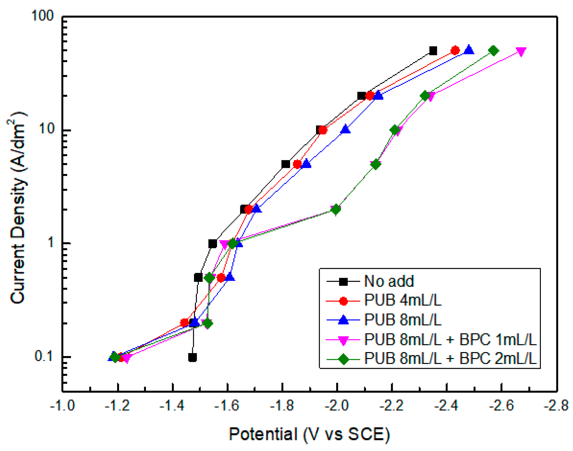
Figure 3 shows the potentiodynamic polarization curves representing the zinc electrodeposition behavior according to the plating conditions. Compared to the case of no organic additives, as PUB was added, the cathode potential of the polarization curve shifted in the negative direction because seemingly, the electron e generated in Equation (4) is not immediately used for the reaction and it accumulates on the surface of the cathode, shifting the potential in the negative direction. This suggests that PUB lowers the rate of ion movement to the electrodeposited site, which is similar to the PVA effect in Equation (7). When BPC, a brightener, was added to PUB, the cathodic potential of the polarization curve shifted further in the negative direction. This suggests that the particles of the precipitate became finer and that a bright plating layer was formed as a result of the BPC slowing the ion movement. The shift in the negative direction of the cathode potential with the addition of organic additives was only observed in the current density range of 50 to 1 ASD (A/dm2). This mechanism does not seem to occur below 0.5 ASD.
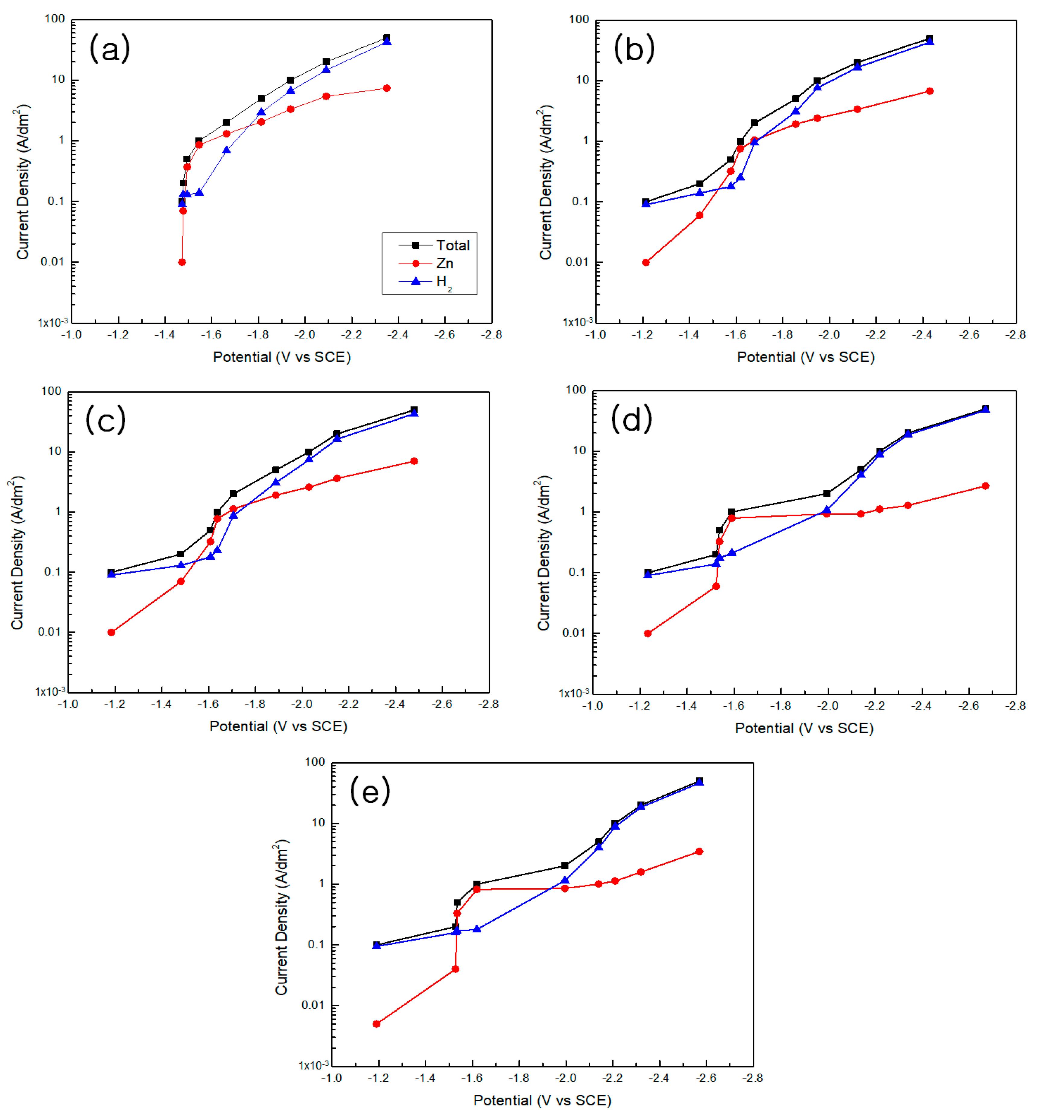
Figure 4 shows the partial polarization curves for zinc (Zn) and hydrogen (H2) according to the plating conditions (note that, for example, the label “PUB 4 mL” denotes 4 mL of the PUB additive, and the same notation is used for this and other additive amounts hereinafter). The partial polarization curve of zinc was calculated by multiplying the total current density with the current efficiency for zinc plating. The partial polarization curve for hydrogen was obtained by subtracting the current density for the zinc deposition reaction from the total current density. Overall, the polarization curve for hydrogen evolution was higher than that of zinc at high current densities. In the range of 2 to 0.5 ASD, the polarization curve for zinc plating was higher than that for hydrogen generation, as the current efficiency for zinc plating exceeded 50%.
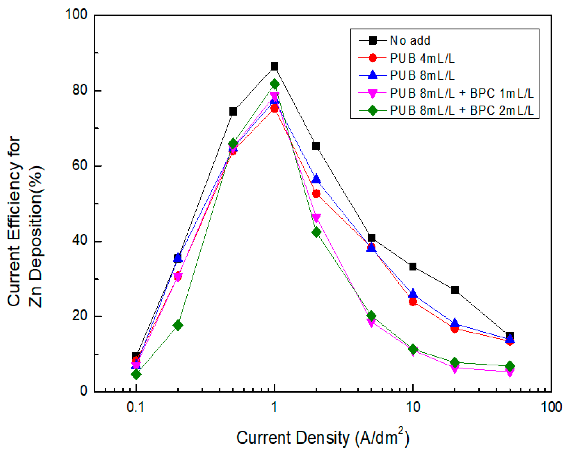
Figure 5 shows the current efficiency of zinc precipitates for zinc electroplating according to the plating conditions. The current efficiency was the highest without additives because zinc was deposited rapidly. As PUB was added, the rate of the precipitation reaction decreased, resulting in a decrease in the current efficiency. When BPC was also added, the current efficiency reduced further, and therefore, the rate of the precipitation reaction reduced further. Overall, the current efficiency was low in the high current density range, and the current efficiency increased as the current density decreased. The best current efficiency was found to be in the range of 2 to 0.5 ASD. When the current density decreased below 0.5 ASD, the current efficiency decreased, which is similar to the effect observed at high current densities.
3.2. Morphology of Zinc (Zn) Surface
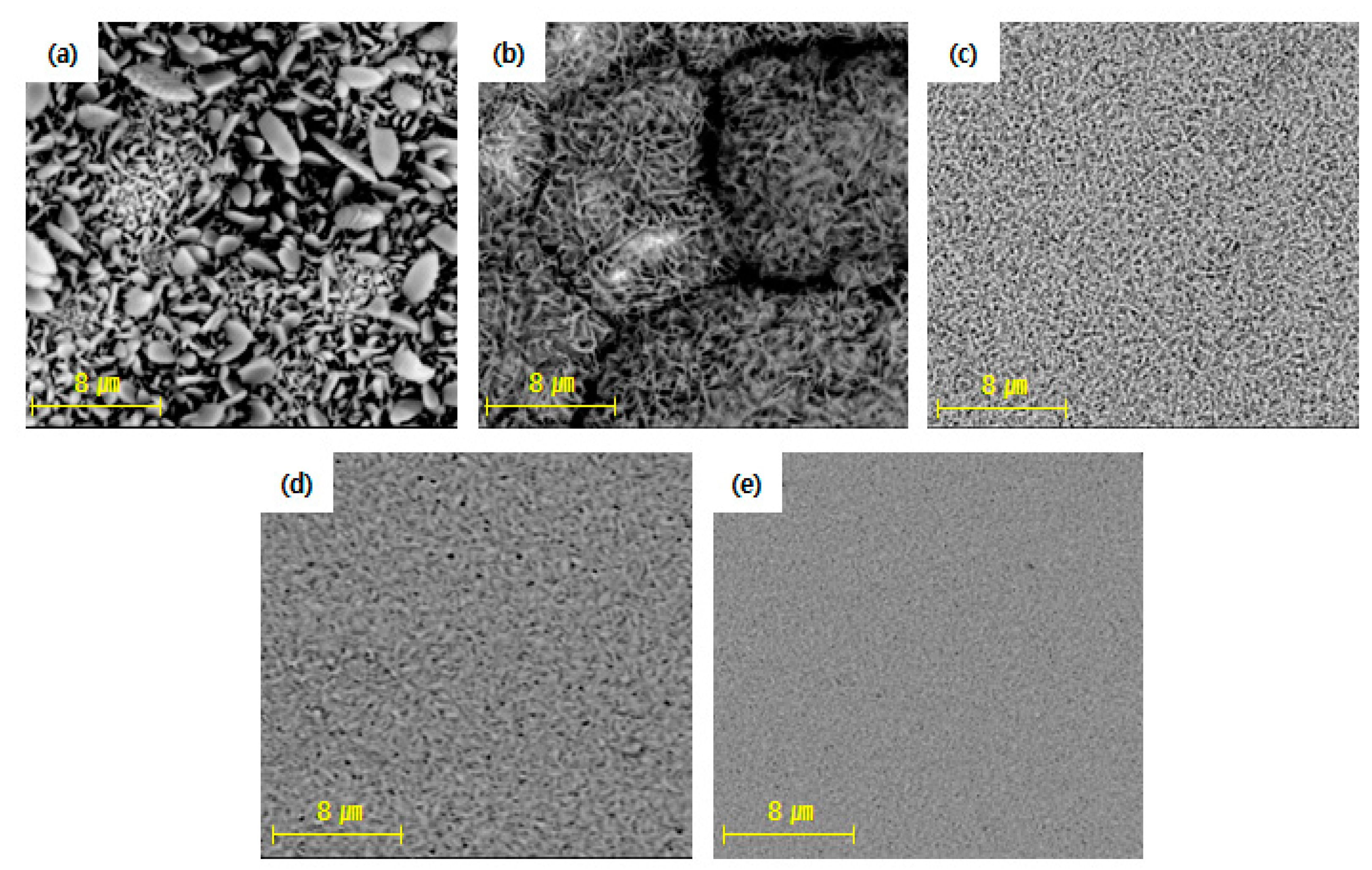
Figure 6 shows the SEM images of the structure of the Zn plating deposits according to the composition of additives or without additives at a current density of 4 ASD (A/dm2). An increase in the amount of organic additives increases the precipitation overpotential of zinc, which refines the crystal grains [18,19]. In addition, free active surface sites on the cathode are blocked, thereby improving electrodeposition. Therefore, the heterogeneous and rapid growth of zinc is restricted, and the nuclear density is correspondingly promoted [6]. When plated without additives, the zinc exhibited round leaf shapes that were stacked on top of each other, resulting in a rough surface. The crystal grains were refined and changed to needle-like shapes as PUB was added. Therefore, a somewhat smooth surface was obtained when 8 mL of PUB was added. When PUB and BPC were both added, the needle-like shapes changed to slightly angular spheres, and a smoother surface was achieved.
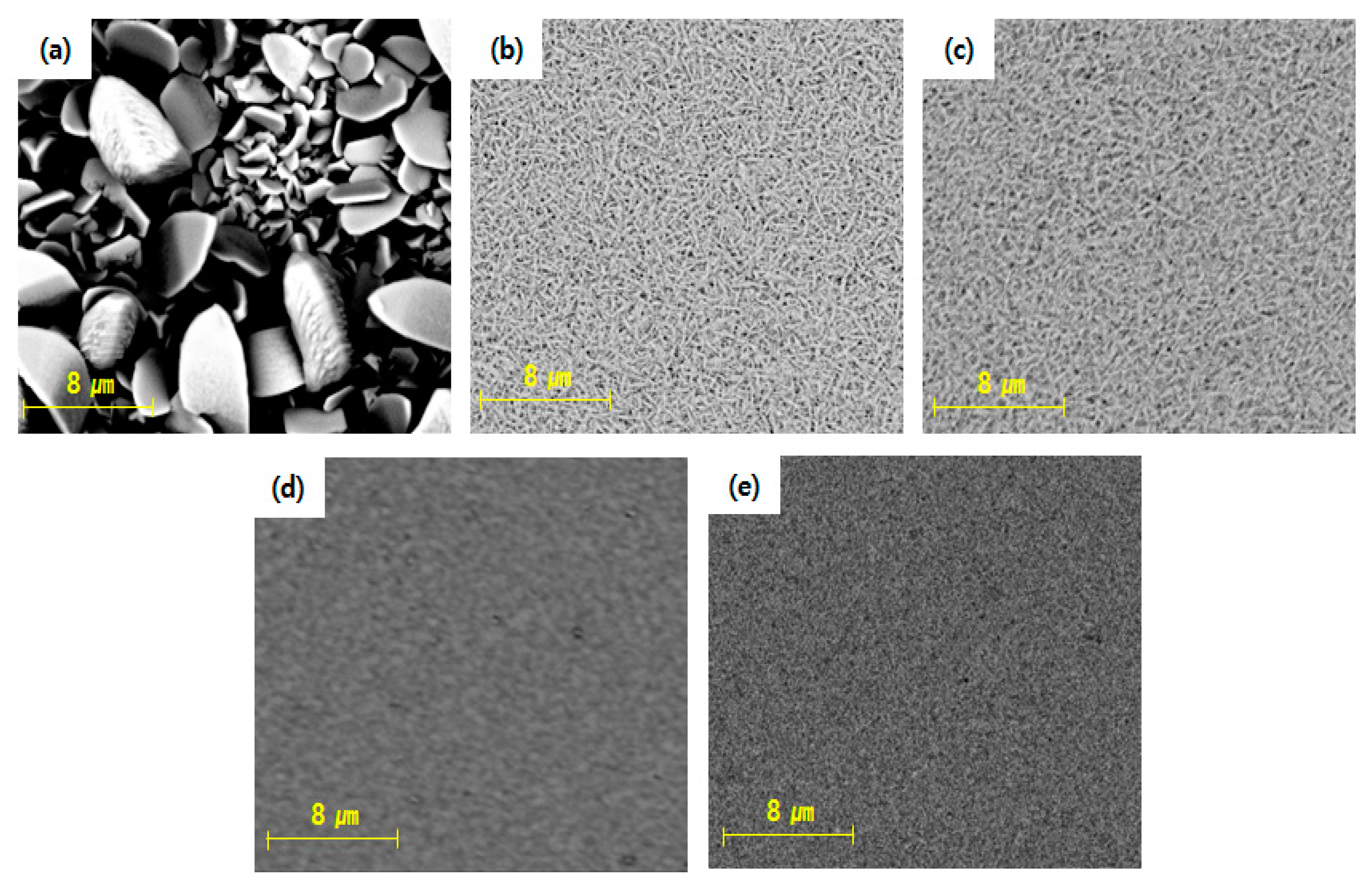
Figure 7 shows the SEM images of the zinc plating deposit structures according to the additive composition and without additives at the current density of 2 ASD (A/dm2). In the case of plating without additives, the structure was slightly larger than that at 4 ASD. As the organic additive was added, the crystal grains were refined and changed to needle-like shapes, similar to the case of 4 ASD, showing a smooth surface. When PUB and BPC were both added, the needle-like shapes changed to slightly angular spherical shapes, similar to those obtained at 4 ASD.
3.3. XRD Patterns
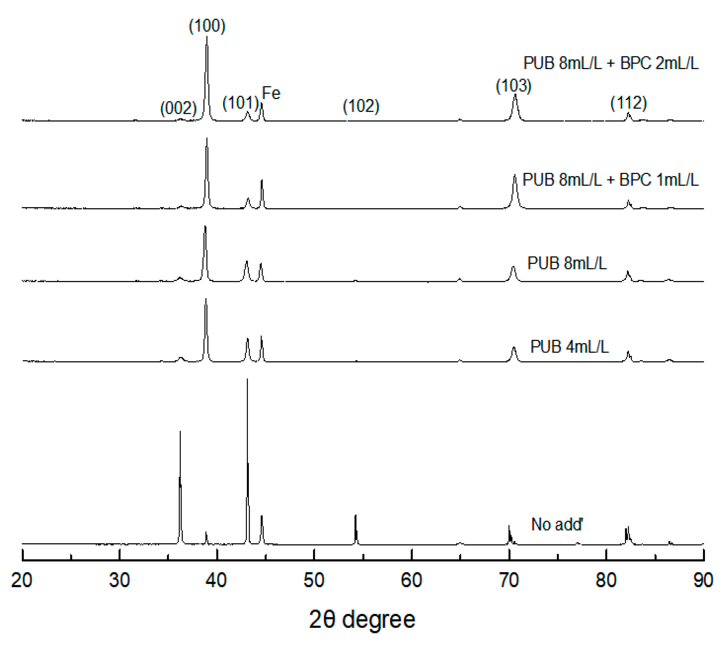
Figure 8 shows XRD diffractograms of zinc deposits according to the composition of added additives and without additives. In the absence of additives, the (002) plane, which is the base plane, was preferentially oriented, and the peak of the (101) plane, which is a high-angle pyramid plane tilted at an angle of 65° from the base material, was large [18]. Therefore, the (002) and (101) planes were preferentially oriented in the non-additive case, in which the mass transfer of zinc was promoted. When an additive is added, the preferential orientation changes to the (100) plane because it hinders the movement of zinc and increases the precipitation overpotential. Such a change in the preferential orientation is also related to the shape or size of the crystal grains. The (002) plane has large crystal grains and a hexagonal plate shape. As the preferential orientation changes from the pyramid (104), (103), (112), and (101) planes to the prism (110) and (100) planes, the crystal grains become finer and rounder [18].
Figure 9 shows the grain sizes of the zinc deposits without additives and according to the composition of added additives. In the absence of additives, the crystal grain size is the largest, as shown in the SEM images in Figure 6 and Figure 7. As the additives are added, the rapid growth of zinc is restricted, and the precipitation overpotential is increased, resulting in a finer grain size.
3.4. Appearance of the Plating Layer Surface
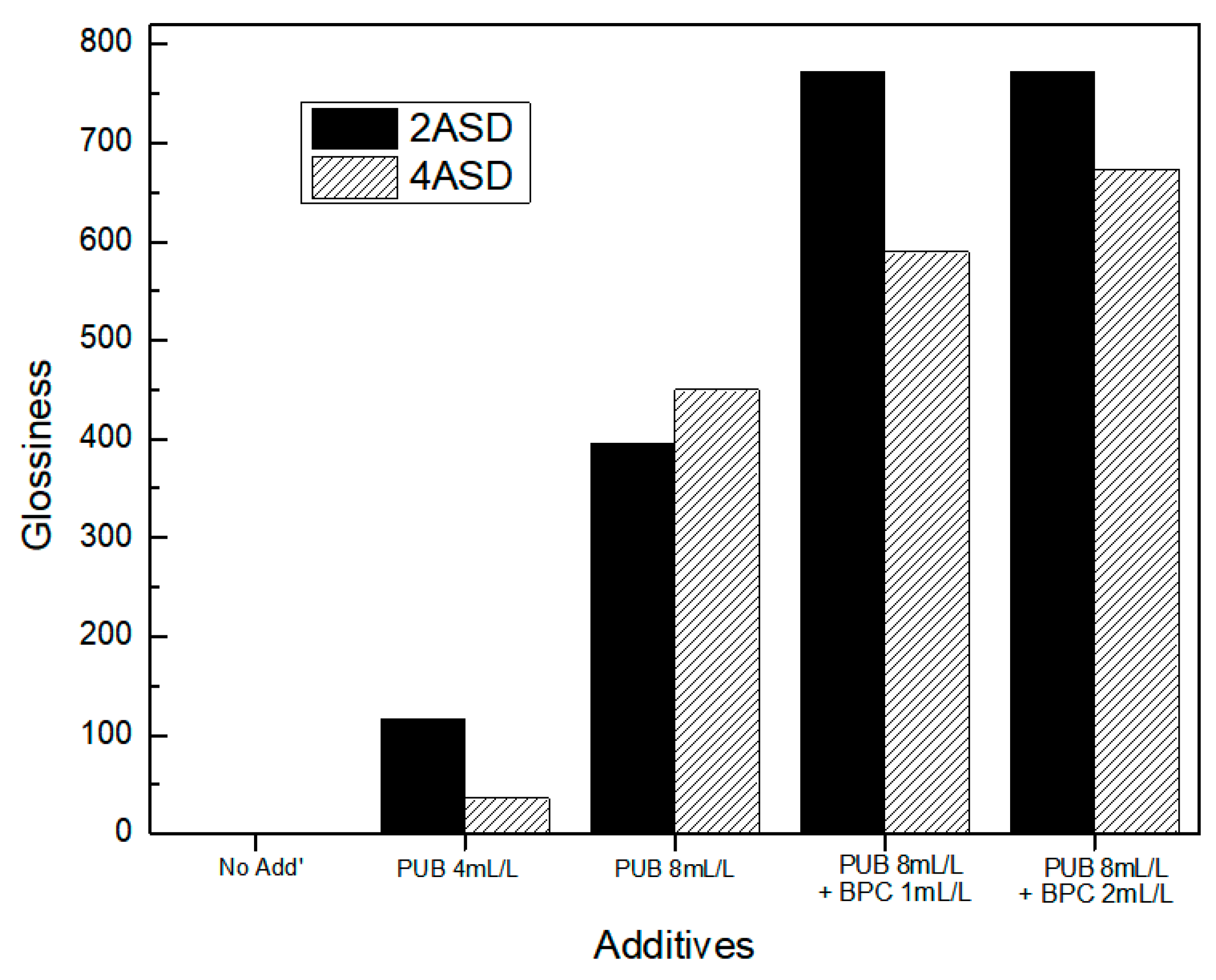
Figure 10 shows the glossiness of the zinc plating layers without additives and according to the composition of added additives. Glossiness refers to the degree of gloss on the surface [20], and a change in the glossiness of a coated specimen occurs because of the fine particles of the coating layer and their preferential orientation [21]. When plated without additives, little gloss is observed because the zinc deposits are stacked non-directionally on top of each other, resulting in a rough surface. As PUB is added, the crystal grains of the zinc deposit are refined, the glossiness increases, and a smooth surface is obtained. As BPC, a brightening agent, is added, the crystal grains become finer, and the shape changes from a needle-shape to a spherical shape, which further increases the glossiness.
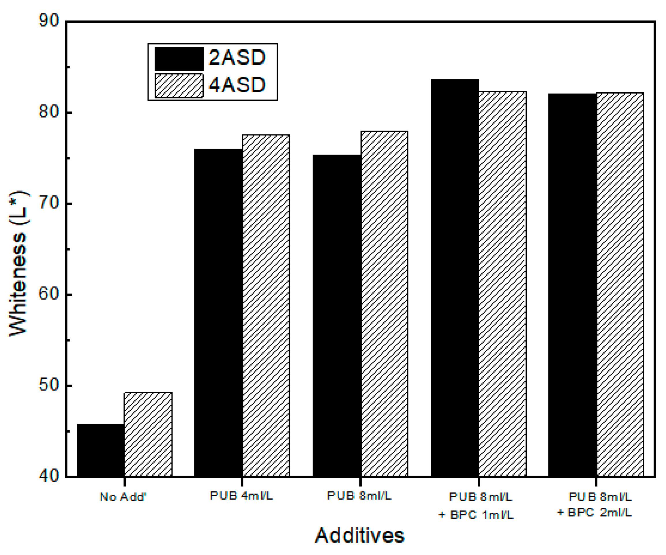
Figure 11 shows the whiteness of the zinc plating layer without additives and according to the composition of added additives. Whiteness is an index related to the color sense of an object and is a value that measures the contrast of the surface color [20]. The L* value is data measured for reflectance using a spectrophotometer, and represents the similar brightness as human vision and is displayed as a value from 0 to 100. As with glossiness, the lowest whiteness value was obtained when no additive existed. As PUB was added, the whiteness value increased like the glossiness. As BPC, a brightening agent, was added, the whiteness value increased further. The glossiness and whiteness of coated specimens are affected by the preferential orientation of crystal planes and the size of fine particles and crystal grains in the coating layer [18,21]. When the preferential orientation is changed to the prism plane (100), the crystal grains become finer, and the glossiness and whiteness increase as the shape becomes round.
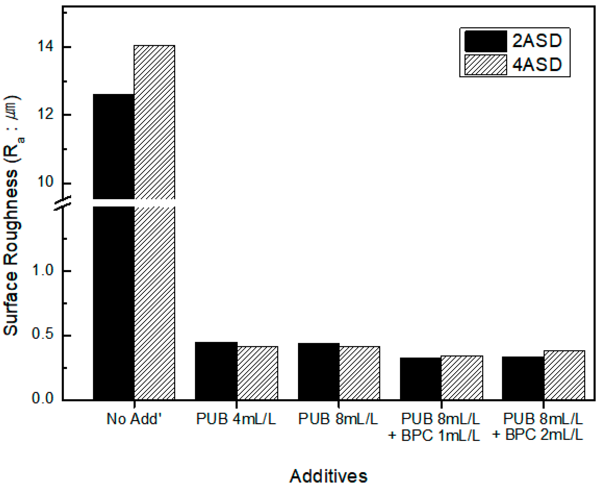
Figure 12 shows the surface roughness of the zinc plating layer without additives and according to the composition of added additives. When plated without additives, the surface roughness is high. When PUB is added, the surface roughness is greatly reduced. The PUB leveler increases the nucleation rate rather than increasing the nucleus and refining the crystal grains, reducing the surface roughness [18,22]. The result is the same as that for the grain size shown in Figure 5. When BPC, a brightener, is added, the surface roughness tends to decrease slightly.
3.5. Throwing Power
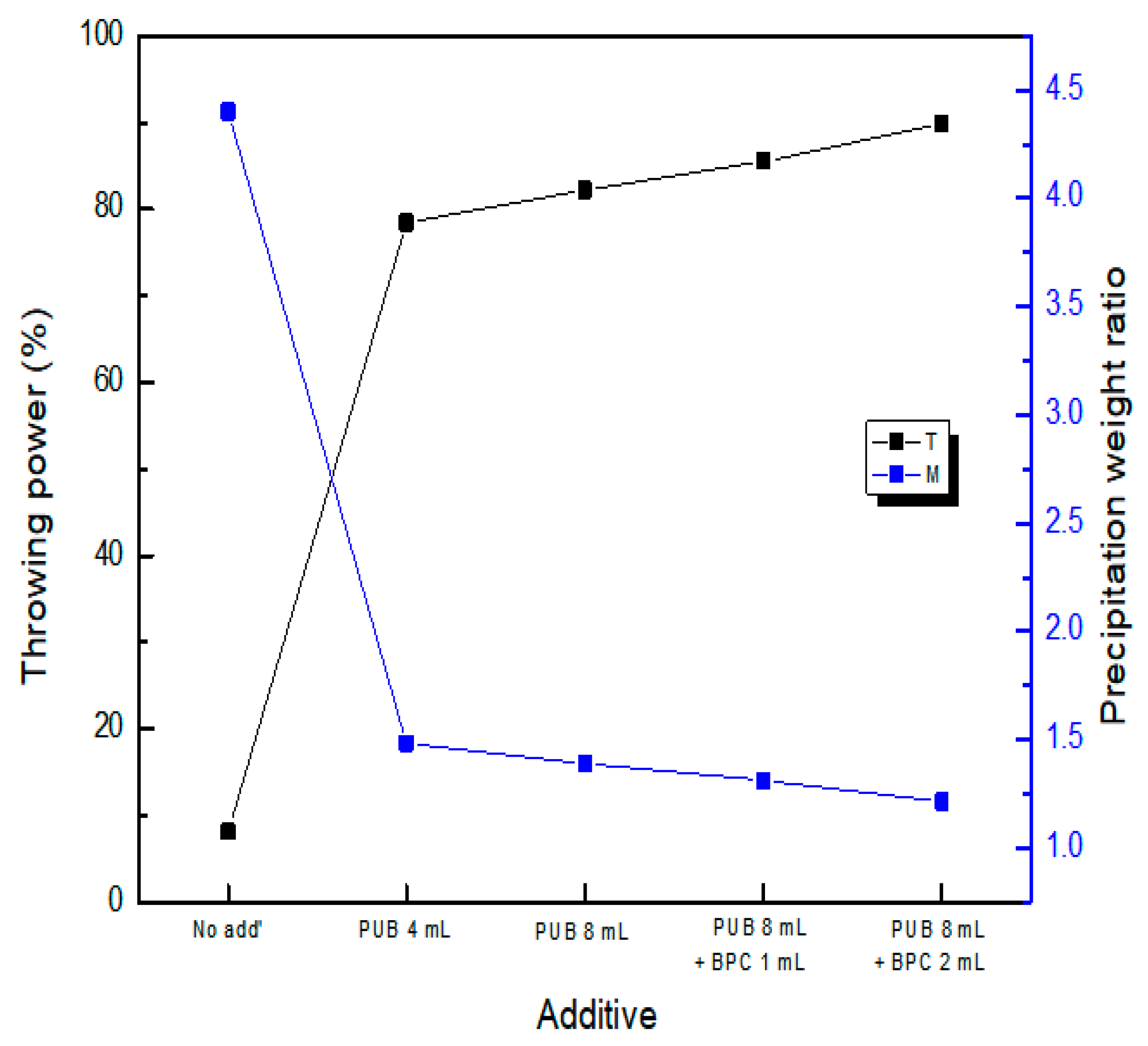
Solutions with an ideal throwing power appear at a metal precipitation weight ratio (M) = 1. The ratio increases rapidly in plating baths with a low throwing power [13]. The throwing power depends on plating parameters such as the zinc concentration, pH, current density, temperature, and plating duration. Some studies have shown that additives can improve the throwing power in non-cyanide zinc plating baths [1]. Figure 13 shows the throwing power (TP (%)) and metal precipitation weight ratio (M) of both cathode specimens according to the composition of the additives added and without additives at a current density of 2 ASD (A/dm2). In the case of plating without additives, the throwing power was low because the zinc plating precipitation weight of the cathode specimen near the anode was approximately 4.4 times higher than the zinc plating precipitation weight of the cathode specimen that was far from the anode. As the additives were added, the zinc precipitation overpotential increased, and the rapid and non-uniform growth of zinc was restricted. As a result, the zinc plating precipitation weight reduced. In other words, the metal precipitation ratios (M) of both negative plates decreased as the zinc plating precipitation weight of the cathode specimen near the anode reduced. Conversely, the throwing power increased.
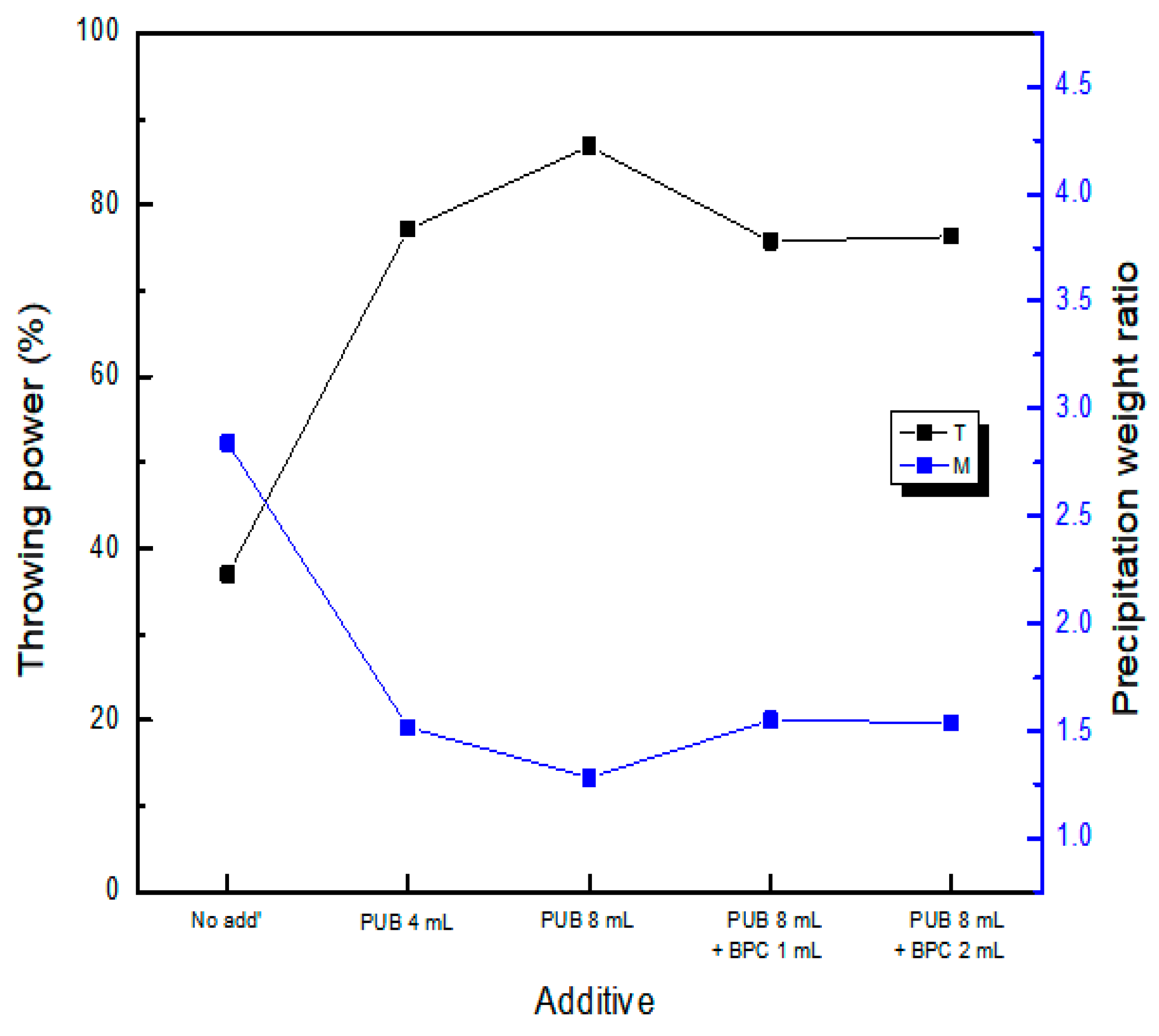
Figure 14 shows the throwing power and metal precipitation weight ratio of both cathode specimens without additives and according to the composition of added additives at a current density of 4 ASD. In the absence of additives, the throwing power is low because the zinc plating precipitation weight of the cathode specimen near the anode is approximately 2.8 times higher than the zinc plating precipitation weight of the cathode specimen far from the anode. The metal precipitation ratio (M) decreased compared to that at 2 ASD because the zinc plating precipitation weight of the cathode specimen farther from the anode increased as the applied current increased. When PUB was added, the throwing power increased as the metal precipitation weight ratio (M) decreased, which is similar to that at 2 ASD. However, when BPC, a brightening agent, was added, the throwing power decreased, in contrast to the results at 2 ASD. When BPC was added, the amount of zinc plating was reduced for both cathode specimens. However, the metal precipitation weight ratio (M) increased, and the throwing power decreased because the galvanized precipitation weight of the cathodic specimen farther from the anode decreased further.
4. Conclusions
We investigated how organic additives to an alkaline non-cyanide zinc electroplating bath affect the resulting microstructure and properties of the electrodeposits obtained. The following conclusions were drawn from the results:
In alkaline non-cyanide zinc electroplating, the speed of ions moving to the electrodeposition site is reduced to refine the particles and form a bright plating layer in the presence of organic additives. As PUB and BPC were added, the cathode potential of the polarization curve shifted in the negative direction. In addition, the current efficiency for zinc plating gradually decreased at high current densities as PUB and BPC were added.
In the case of plating without additives, the surfaces of the zinc deposits exhibited round leaf shapes and rough surfaces as they were stacked on top of each other. However, as PUB was added, the crystal grains were refined and changed to a needle-like shape, resulting in a relatively smooth surface shape. When PUB and BPC were combined, the needle shape changed to a slightly angular spherical shape with a smoother surface.
In the XRD pattern obtained in the case of plating without additives, the (002) plane, which is the basal plane, was preferentially oriented, and a strong peak of the (101) plane appeared. However, with additives, the preferential orientation changed to the (100) plane because the precipitation and voltage increased as the movement of zinc was hindered. The crystal grain size was the largest without additives. As PUB and BPC were added, the size of the crystal grains was refined.
The glossiness of the surface of the plating layer increased when PUB was added and increased further when BPC was added. The whiteness also increased as PUB and BPC were added. The surface roughness was high in the case of plating without additives. When PUB was added, the surface roughness decreased to less than 0.5 µm. When BPC was added, it decreased slightly further.
The throwing power increased the zinc precipitation overpotential as PUB and BPC were added, limiting the zinc’s rapid and uneven growth. Therefore, the metal precipitation weight ratio (M) decreased, and the zinc plating precipitation weight of the cathode specimen near the anode decreased significantly. Conversely, the throwing power increased. At a current density of 2 ASD, the throwing power increased as PUB and BPC were added. At 4 ASD, the throwing power increased as PUB was added. However, the throwing power decreased slightly when BPC was added.
Author Contributions
Data curation, S.-B.J.; Funding acquisition, B.-K.S.; Methodology, S.-B.J.; Project administration, B.-K.S.; Resources, J.-W.C.; Software, J.-W.C.; Supervision, I.S.; Writing–original draft, S.-B.J.; Writing–review & editing, I.S. All authors have read and agreed to the published version of the manuscript.
Funding
This research was funded by the Ministry of SMEs and Startups as part of the 2021 Process and Quality Technology Development Project (Innovative R&D_General Project, S3142840).
Institutional Review Board Statement
Not applicable.
Informed Consent Statement
Not applicable.
Data Availability Statement
The authors confirm that the data supporting the findings of this study are available within the article.
Conflicts of Interest
The authors declare no conflict of interest.
References
- Mohammed, A.J.; Moats, M. Effects of Carrier, Leveller, and Booster Concentrations on Zinc Plating from Alkaline Zincate Baths. Metals 2022, 12, 621. [Google Scholar] [CrossRef]
- Keyvani, A.; Yeganeh, M.; Rezaeyan, H. Electrodeposition of Zn-Co-Mo Alloy on the Steel Substrate from Citrate Bath and Its Corrosion Behavior in the chloride Media. J. Mater. Eng. Perform. 2017, 26, 1958–1966. [Google Scholar] [CrossRef]
- Rouabhia, F.; Hamlaoui, Y.; Meroufel, A.; Pedraza, F. Corrosion properties of ceria-based coating electrodeposited from alkaline bath on electrogalvanized steel. J. Appl. Electrochem. 2021, 51, 567–580. [Google Scholar] [CrossRef]
- El Fazazi, A.; Ouakki, M.; Cherkaoui, M. Electrochemical Deposition and Spectroscopy Investigation of Zn coatings on Steel. J. Bio Tribo-Corros. 2021, 7, 58. [Google Scholar] [CrossRef]
- Kancharla, H.; Mandal, G.K.; Maharana, H.S.; Singh, S.S.; Mondal, K. Structure-Dependent Corrosion Behavior of Electrodeposited Zn Coating. J. Mater. Eng. Perform. 2023, 32, 2993–3006. [Google Scholar] [CrossRef]
- Chotirach, M.; Rattanawaleedirojn, P.; Boonyongmaneerat, Y.; Chanajaree, R.; Schmid, K.; Metzner, M.; Rodthongkum, N. Systematic investigation of brightener’s effects on alkaline non-cyanide zinc electroplating using HPLC and molecular modeling. Mater. Chem. Phys. 2022, 277, 125567. [Google Scholar] [CrossRef]
- Oniciu, L.; Mureşan, L. Some fundamental aspects of levelling and brightening in metal electrodeposition. J. Appl. Electrochem. 1991, 21, 565–574. [Google Scholar] [CrossRef]
- Thomas, J.D. Leveling, Definition, Measurement and Understanding. Proc. Am. Electropl. Soc. 1956, 43, 60–67. [Google Scholar]
- Kardos, O.; Foulke, D.G. Title of the chapter. In Advances in Electrochemistry and Electrochemical Engineering; Tobias, C.W., Ed.; lnterscience Publishers: New York, NY, USA, 1966; Volume 2, p. 145. [Google Scholar]
- Kohlschuter, V. Trans. Electrochem. Soc. 1924, 45, 229.
- Liebreich, E. The effects of film formation on the structure of electro-deposited metallic coatings. Trans. Faraday Soc. 1935, 31, 1188–1194. [Google Scholar] [CrossRef]
- Monshi, A.; Foroughi, M.R.; Monshi, M.R. Modified Scherrer Equation to Estimate More Accurately Nano-Crystallite Size Using XRD. World J. Nano Sci. Eng. 2012, 2, 154–160. [Google Scholar] [CrossRef]
- Ibrahim, M.A.M. Improving the throwing power of acidic zinc sulfate electroplating baths. J. Chem. Technol. Biotechnol. 2000, 75, 745–755. [Google Scholar] [CrossRef]
- Ahmed, A.; Shaaban, A.J. Evaluation of some new organic additives with alternative function groups in cyanide-free alkaline zinc electroplating. Sci. Arts 2012, 2, 169–176. [Google Scholar]
- Ortiz-Aparicio, J.L.; Meas, Y.; Trejo, G.; Ortega, R.; Chapman, T.W.; Chainet, E. Effects of organic additives on zinc electrodeposition from alkaline electrolytes. J. Appl. Electrochem. 2013, 43, 289–300. [Google Scholar] [CrossRef]
- Kavitha, B.; Santhosh, P.; Renukadevi, M.; Kalpana, A.; Shakkthivel, P.; Vasudevan, T. Role of organic additives on zinc plating. Surf. Coat. Technol. 2006, 201, 3438–3442. [Google Scholar] [CrossRef]
- Bae, S.H.; Oue, S.; Son, I.J.; Nakano, H. Effect of Reaction Product of Epichlorohydrin and Imidazole on the Electrodeposition Behavior of Zn–Ni Alloy from Alkaline Zincate Solution. ISIJ Int. 2021, 61, 2256–2263. [Google Scholar] [CrossRef]
- Jung, S.S.; Kim, B.I.; Kim, Y.-G. Effects of Composition of Organic Additives and Electrolytic Conditions on Surface Appearance of Electrodeposited Zinc. Korean J. Met. Mater. 2004, 42, 597–602. [Google Scholar]
- Gavrila, M.; Millet, J.P.; Mazille, H.; Marchandise, D.; Cuntz, J.M. Corrosion behaviour of zinc–nickel coatings, electrodeposited on steel. Surf. Coat. Technol. 2000, 123, 164–172. [Google Scholar] [CrossRef]
- Kim, H.T.; Chung, W.S.; Cho, N.W. The Effect of the Polyethylenglycol on Electrocrystallization of Zinc Coat. J. Korean Inst. Surf. Eng. 1997, 30, 128–135. [Google Scholar]
- Kim, H.T.; Kim, T.Y.; Lee, R.R.; Chang, S.K. The effect of polyethyleneglycol on the electrocrystallization of Zn electrodeposition. J. Korean Cryst. Growth 1999, 9, 590–596. [Google Scholar]
- Inoue, K.; Nakata, T.; Shindo, Y.; Watanabe, T. Surface Morphology and Crystallographic Orientation of Electrodeposited Gold Films. J. Jpn. Inst. Met. 2002, 66, 400–408. [Google Scholar] [CrossRef]
Figure 1.
Schematic of the polarization process.

Figure 2.
Schematic of the Haring–Blum cell.

Figure 3.
Cathodic potentiodynamic polarization curves of Zn electrodeposits with different additive combinations.
Figure 3.
Cathodic potentiodynamic polarization curves of Zn electrodeposits with different additive combinations.

Figure 4.
Partial polarization curves of zinc and hydrogen with different additive combinations: (a) No additive, (b) PUB 4 mL, (c) PUB 8 mL, (d) PUB 8 mL and BPC 1 mL, and (e) PUB 8 mL and BPC 2 mL.
Figure 4.
Partial polarization curves of zinc and hydrogen with different additive combinations: (a) No additive, (b) PUB 4 mL, (c) PUB 8 mL, (d) PUB 8 mL and BPC 1 mL, and (e) PUB 8 mL and BPC 2 mL.

Figure 5.
Current efficiency of Zn electrodeposits with different additive combinations.

Figure 6.
SEM images of Zn deposits obtained with different additive combinations (4ASD): (a) No additive, (b) PUB 4 mL, (c) PUB 8 mL, (d) PUB 8 mL and BPC 1 mL, and (e) PUB 8 mL and BPC 2 mL.
Figure 6.
SEM images of Zn deposits obtained with different additive combinations (4ASD): (a) No additive, (b) PUB 4 mL, (c) PUB 8 mL, (d) PUB 8 mL and BPC 1 mL, and (e) PUB 8 mL and BPC 2 mL.

Figure 7.
SEM images of Zn deposits obtained with different additives (2 ASD): (a) No additive, (b) PUB 4 mL, (c) PUB 8 mL, (d) PUB 8 mL and BPC 1 mL, and (e) PUB 8 mL and BPC 2 mL.
Figure 7.
SEM images of Zn deposits obtained with different additives (2 ASD): (a) No additive, (b) PUB 4 mL, (c) PUB 8 mL, (d) PUB 8 mL and BPC 1 mL, and (e) PUB 8 mL and BPC 2 mL.

Figure 8.
X-ray diffraction patterns of Zn electrodeposits with different additive combinations.

Figure 9.
Grain sizes of Zn electrodeposits with different additive combinations.

Figure 10.
Glossiness of Zn electrodeposits with different additives.

Figure 11.
Whiteness of Zn electrodeposits for different additive combinations.

Figure 12.
Surface roughness of Zn electrodeposits for different additive combinations.

Figure 13.
Throwing power of Zn electrodeposits for different additive combinations (2 ASD).

Figure 14.
Throwing power of Zn electrodeposits for different additive combinations (4 ASD).


Table 1.
Properties of the studied organic additives.
| Additives | Structural Formula Image | CAS No. | Molecular Formula |
|---|---|---|---|
| PUB (Polyquaternium-2) |  | 68555-36-2 | C15H34Cl2N4O2 |
| BPC |  | 15990-43-9 | C13H11NO2 |
Disclaimer/Publisher’s Note: The statements, opinions and data contained in all publications are solely those of the individual author(s) and contributor(s) and not of MDPI and/or the editor(s). MDPI and/or the editor(s) disclaim responsibility for any injury to people or property resulting from any ideas, methods, instructions or products referred to in the content. |
© 2023 by the authors. Licensee MDPI, Basel, Switzerland. This article is an open access article distributed under the terms and conditions of the Creative Commons Attribution (CC BY) license (https://creativecommons.org/licenses/by/4.0/).
Share and Cite
MDPI and ACS Style
Jeon, S.-B.; Son, B.-K.; Choi, J.-W.; Son, I. Effects of Organic Additives on Alkaline Non-Cyanide Zinc Electroplating. Coatings 2023, 13, 781. https://doi.org/10.3390/coatings13040781
AMA Style
Jeon S-B, Son B-K, Choi J-W, Son I. Effects of Organic Additives on Alkaline Non-Cyanide Zinc Electroplating. Coatings. 2023; 13(4):781. https://doi.org/10.3390/coatings13040781
Chicago/Turabian StyleJeon, Su-Byung, Byung-Ki Son, Ji-Won Choi, and Injoon Son. 2023. "Effects of Organic Additives on Alkaline Non-Cyanide Zinc Electroplating" Coatings 13, no. 4: 781. https://doi.org/10.3390/coatings13040781
Note that from the first issue of 2016, this journal uses article numbers instead of page numbers. See further details here.