
Thermal Barrier Coatings for High-Temperature Performance of Nickel-Based Superalloys: A Synthetic Review
 ,
,  , and
, and
Abstract
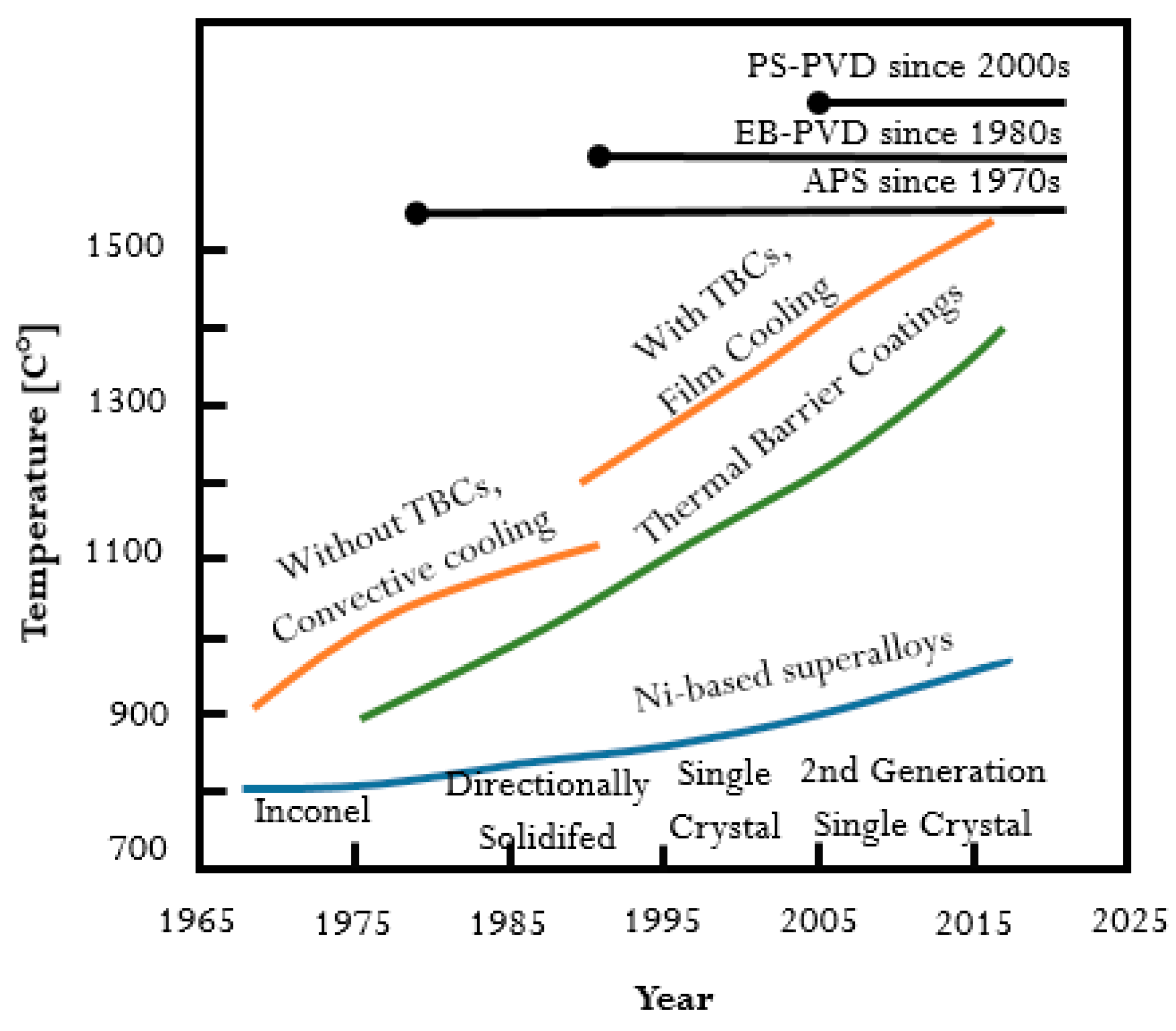
:1. Introduction
2. Review Methodology
3. Deposition of TBC Layers
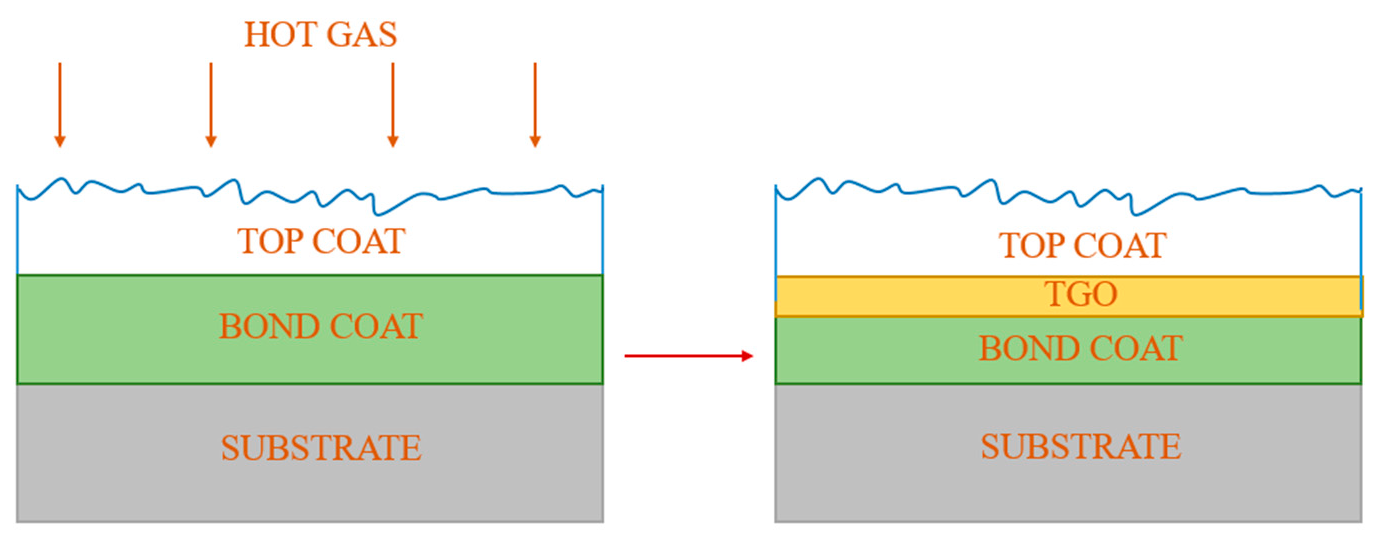
- the formation of microcracks in the topcoat, through which oxygen reacts with the metal to form Al2O3 scale; or
- the diffusion of oxygen from the YSZ decomposition.
- -
- lower density than stainless steels, and better strength-to-weight ratio;
- -
- higher Al content (in the range of 15–30 wt.% depending on the intermetallic) as compared to Al content of 6 wt.% or less in steels and superalloys;
- -
- excellent oxidation resistance up to 1000 °C;
- -
- better corrosion resistance in oxidizing and reducing environments;
- -
- the ability to either reduce or eliminate the application of strategic elements such as Cr;
- -
- the ability to match thermal expansion properties with those of the steels;
- -
- high electrical resistivity that increases with temperature;
- -
- good corrosion resistance in many aqueous environments.

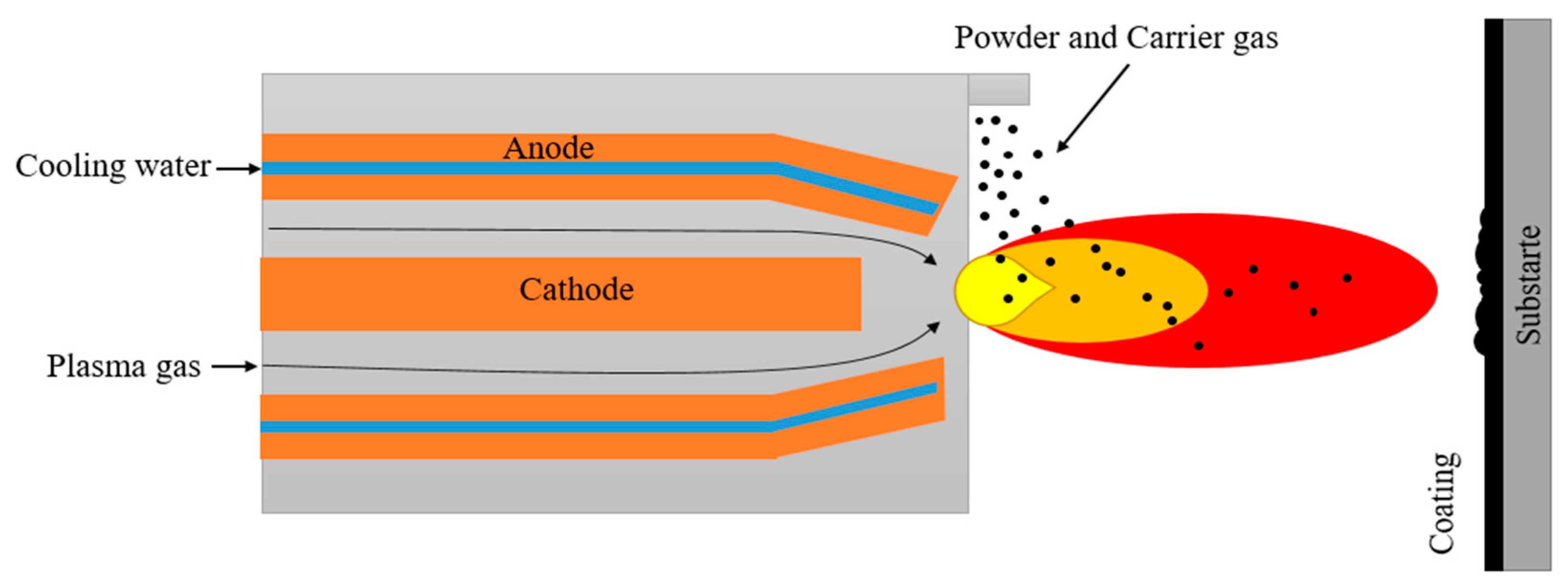
3.1. Thermal Sprayed Methods
- atmospheric plasma spraying (APS) carried out in a controlled air atmosphere;
- low-pressure plasma spraying/vacuum plasma spraying (LPPS/VPS) performed under controlled vacuum (at pressures of 3–7 kPa);
- very low-pressure plasma spraying (VLPPS), which is also performed under a controlled vacuum within the pressure range from 50 Pa to 200 Pa [30];
- suspension plasma spray (SPS) and solution precursor plasma spray (SPPS) processes [31] in which the coating material is delivered into the plasma jet as suspended solid particles in a nanometer or micron size range (in the SPS process) or an aqueous or non-aqueous solution (which is fed into the plasma) containing the cations necessary to form the oxide coating (in the SPPS process).

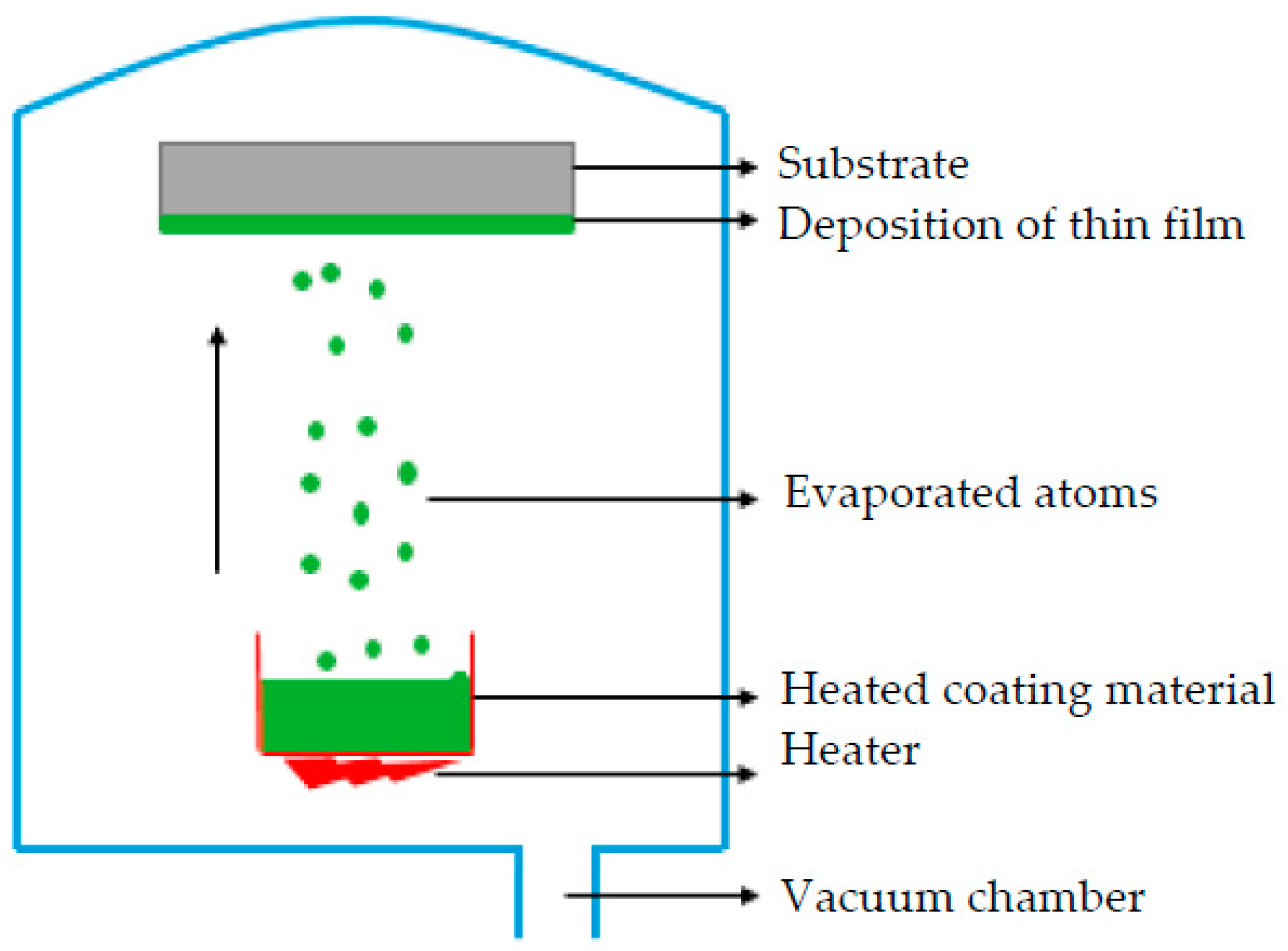
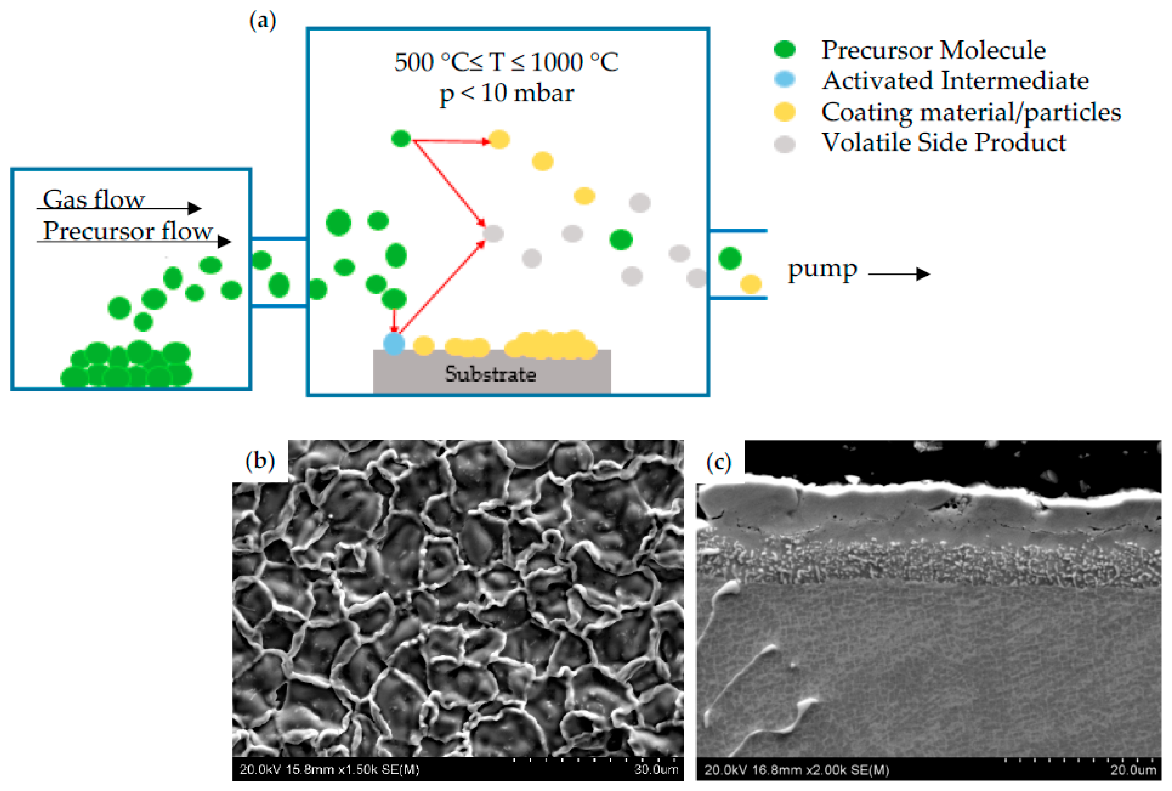
3.2. Vapor Deposition Techniques
3.3. Perspective Methods—Physical Vapor Deposition (PS-PVD), Suspension Plasma Spray (SPS)
4. Effect of Deposition Methods on Corrosion Resistance and Mechanical Properties
4.1. Effect of TBC on Corrosion Resistance

4.2. Effect of TBC on Mechanical Properties
5. Conclusions and Future Trends
Author Contributions
Funding
Institutional Review Board Statement
Informed Consent Statement
Data Availability Statement
Conflicts of Interest
References
- Pavlenko, D.; Dvirnyk, Y.; Przysowa, R. Advanced materials and technologies for compressor blades of small turbofan engines. IOP Conf. Ser. Mater. Sci. Eng. 2021, 1024, 012061. [Google Scholar] [CrossRef]
- Sahith, M.; Giridhara, G.; Kumar, S.R. Development and analysis of thermal barrier coatings on gas turbine blades—A Review. Mater. Today Proc. 2018, 5, 2746–2751. [Google Scholar] [CrossRef]
- Szczepankowski, A.; Przysowa, R. Thermal degradation of turbine components in a military turbofan. Eng. Fail. Anal. 2022, 134, 106088. [Google Scholar] [CrossRef]
- Przysowa, R. Blade Vibration Monitoring in a Low-Pressure Steam Turbine. In Proceedings of the ASME Turbo Expo 2018: Turbomachinery Technical Conference and Exposition, Oslo, Norway, 11–15 June 2018; Ceramics; Controls, Diagnostics, and Instrumentation; Education; Manufacturing Materials and Metallurgy. ASME: New York, NY, USA, 2018; Volume 6, p. V006T05A025. [Google Scholar]
- Chellaganesh, D.; Khan, M.A.; Jappes, J.T.W. Thermal barrier coatings for high temperature applications—A short review. Mater. Today Proc. 2021, 45, 1529–1534. [Google Scholar] [CrossRef]
- Naik, S. Basic Aspects of Gas Turbine Heat Transfer. In Heat Exchangers; Murshed, S.M.S., Lopes, M.M., Eds.; IntechOpen: Rijeka, Croatia, 2017; pp. 111–143. [Google Scholar]
- Zhang, X.; Deng, Z.; Li, H.; Mao, J.; Deng, C.; Deng, C.; Niu, S.; Chen, W.; Song, J.; Fan, J.; et al. Al2O3-modified PS-PVD 7YSZ thermal barrier coatings for advanced gas-turbine engines. npj Mater. Degrad. 2020, 4, 31. [Google Scholar] [CrossRef]
- Szczepankowski, A.; Przysowa, R.; Perczynski, J.; Kułaszka, A. Health and Durability of Protective and Thermal Barrier Coatings Monitored in Service by Visual Inspection. Coatings 2022, 12, 624. [Google Scholar] [CrossRef]
- Moskal, G. Thermal barrier coatings: Characteristics of microstructure and properties, generation and directions of development of bond. J. Achiev. Mater. Manuf. 2009, 37, 323–331. [Google Scholar]
- Bonaquist, D.; Feuerstein, A.; Buchakjian, L.; Brooks, P. The Role of Thermal Barrier Coating in Maximizing Gas Turbine Engine Efciency and Lowering CO2 Emissions; Praxair Techology, Inc.: Danbury, CT, USA, 2017. [Google Scholar]
- Bakan, E.; Vaßen, R. Ceramic Top coats of Plasma-Sprayed Thermal Barrier Coatings: Materials, Processes, and Properties. J. Therm. Spray Technol. 2017, 26, 992–1010. [Google Scholar] [CrossRef]
- Falcón, J.C.P.; Echeverría, A.; Afonso, C.R.M.; Carrullo, J.C.Z.; Borrás, V.A. Microstructure assessment at high temperature in NiCoCrAlY overlay coating obtained by laser metal deposition. J. Mater. Res. Technol. 2019, 8, 1761–1772. [Google Scholar] [CrossRef]
- Hu, Y.; Cai, C.; Wang, Y.; Yu, H.; Zhou, Y.; Zhou, G. YSZ/NiCrAlY interface oxidation of APS thermal barrier coatings. Corros. Sci. 2018, 142, 22–30. [Google Scholar] [CrossRef]
- Daroonparvar, M.; Yajid, M.A.M.; Yusof, N.M.; Farahany, S.; Hussain, M.S.; Bakhsheshi-Rad, H.R.; Valefi, Z.; Abdolahi, A. Improvement of thermally grown oxide layer in thermal barrier coating systems with nano alumina as third layer. Trans. Nonferrous Met. Soc. China 2013, 23, 1322–1333. [Google Scholar] [CrossRef]
- Deevi, S.C. Advanced intermetallic iron aluminide coatings for high temperature applications. Prog. Mater. Sci. 2021, 118, 100769. [Google Scholar] [CrossRef]
- Senderowski, C.; Cinca, N.; Dosta, S.; Cano, I.G.; Guilemany, J.M. The Effect of Hot Treatment on Composition and Microstructure of HVOF Iron Aluminide Coatings in Na2SO4 Molten Salts. J. Therm. Spray Technol. 2019, 28, 1492–1510. [Google Scholar] [CrossRef] [Green Version]
- Senderowski, C.; Panas, A.J.; Fikus, B.; Zasada, D.; Kopec, M.; Korytchenko, K.V. Effects of Heat and Momentum Gain Differentiation during Gas Detonation Spraying of FeAl Powder Particles into the Water. Materials 2021, 14, 7443. [Google Scholar] [CrossRef]
- Panas, A.J.; Senderowski, C.; Fikus, B. Thermophysical properties of multiphase Fe-Al intermetallic-oxide ceramic coatings deposited by gas detonation spraying. Thermochim. Acta 2019, 676, 164–171. [Google Scholar] [CrossRef]
- Pawlowski, A.; Czeppe, T.; Major, L.; Senderowski, C. Structure Morphology of Fe-Al Coating Detonation Sprayed onto Carbon Steel Substrate. Arch. Metall. Mater. 2009, 54, 783–788. [Google Scholar]
- Pawlowski, A.; Senderowski, C.; Wolczynski, W.; Morgiel, J.; Major, L. Detonation Deposited Fe-Al Coatings Part II: Transmission Electron Microscopy of Interlayers and Fe-Al Intermetallic Coating Detonation Sprayed onto the 045 Steel Substrate. Arch. Metall. Mater. 2011, 56, 71–79. [Google Scholar] [CrossRef] [Green Version]
- Senderowski, C.; Vigilianska, N.; Burlachenko, O.; Grishchenko, O.; Murashov, A.; Stepanyuk, S. Effect of APS Spraying Parameters on the Microstructure Formation of Fe3Al Intermetallics Coatings Using Mechanochemically Synthesized Nanocrystalline Fe-Al Powders. Materials 2023, 16, 1669. [Google Scholar] [CrossRef]
- Lencová, K.; Frank Netrvalová, M.; Vostřák, M.; Lukáč, F.; Mušálek, R.; Česánek, Z.; Houdková, Š. Hot Corrosion Behavior of TWAS and HVOF NiCr-Based Coatings in Molten Salt. Materials 2023, 16, 1712. [Google Scholar] [CrossRef]
- Reinshagen, J.H.; Sikka, V.K. Thermal spraying of selected aluminides. In Thermal Spray Coatings: Properties, Processes and Applications; Bernecki, T.F., Ed.; ASM International: Materials Park, OH, USA, 1991. [Google Scholar]
- Al-Taie, I.; Brigham, R.J.; Lafreniere, Y. High temperature alloys and thermal spray coatings for energy conversion. In Proceedings of the 2nd International Conference on Heat Resistant Materials, Gatlinburg, TN, USA, 11–14 September 1995; Natesan, K., Ganesan, P., Lai, G., Eds.; ASM International: Materials Park, OH, USA, 1995; pp. 437–444. [Google Scholar]
- Senderowski, C.; Bojar, Z. Gas detonation spray forming of Fe–Al coatings in the presence of interlayer. Surf. Coat. Technol. 2008, 202, 3538. [Google Scholar] [CrossRef]
- Kumar, N.; Gupta, M.; Mack, D.E.; Mauer, G.; Vaßen, R. Columnar Thermal Barrier Coatings Produced by Different Thermal Spray Processes. J. Therm. Spray Technol. 2021, 30, 1437–1452. [Google Scholar] [CrossRef]
- Feuerstein, A.; Knapp, J.; Taylor, T.; Ashary, A.; Bolcavage, A.; Hitchman, N. Technical and Economical Aspects of Current Thermal Barrier Coating Systems for Gas Turbine Engines by Thermal Spray and EBPVD: A Review. J. Therm. Spray Technol. 2008, 17, 199–213. [Google Scholar] [CrossRef]
- Ruys, A.J.; Sutton, B.A. Metal-ceramic functionally graded materials (FGMs). In Metal-Reinforced Ceramics; Ruys, A.J., Ed.; Woodhead Publishing: Cambridge, UK, 2021; pp. 327–359. [Google Scholar]
- Juhasz, J.A.; Best, S.M. Surface modification of biomaterials by calcium phosphate deposition. In Surface Modification of Biomaterials; Williams, R., Ed.; Woodhead Publishing: Cambridge, UK, 2011; pp. 143–169. [Google Scholar]
- Wang, M. Composite coatings for implants and tissue engineering scaffolds. In Biomedical Composites, 2nd ed.; Ambrosio, L., Ed.; Woodhead Publishing: Cambridge, UK, 2010; pp. 127–177. [Google Scholar]
- Jordan, E.H.; Jiang, C.; Gell, M. The Solution Precursor Plasma Spray (SPPS) Process: A Review with Energy Considerations. J. Therm. Spray Technol. 2015, 24, 1153–1165. [Google Scholar] [CrossRef]
- Mauer, G.; Jarligo, M.O.; Mack, D.E.; Vaßen, R. Plasma-Sprayed Thermal Barrier Coatings: New Materials, Processing Issues, and Solutions. J. Therm. Spray Technol. 2013, 22, 646–658. [Google Scholar] [CrossRef]
- Devasia, R.; Painuly, A.; Devapal, D.; Sreejith, K.J. Continuous fiber reinforced ceramic matrix composites. In Fiber Reinforced Composites; Joseph, K., Oksman, K., George, G., Wilson, R., Appukuttan, S., Eds.; Woodhead Publishing: Cambridge, UK, 2021; pp. 669–751. [Google Scholar]
- Bakan, E.; Mack, D.E.; Mauer, G.; Vaßen, R.; Lamon, J.; Padture, N.P. High-temperature materials for power generation in gas turbines. In Advanced Ceramics for Energy Conversion and Storage; Guillon, O., Ed.; Elsevier: Amsterdam, The Netherlands, 2020; pp. 3–62. [Google Scholar]
- Fikus, B.; Senderowski, C.; Panas, A.J. Modeling of Dynamics and Thermal History of Fe40Al Intermetallic Powder Particles Under Gas Detonation Spraying Using Propane-Air Mixture. J. Therm. Spray Technol. 2019, 28, 346–358. [Google Scholar] [CrossRef] [Green Version]
- Ramadan, K.; Butler, P.B. Analysis of gas flow evolution and shock wave decay in detonation thermal spraying systems. J. Therm. Spray Technol. 2004, 13, 239–247. [Google Scholar] [CrossRef]
- Chrostek, T. Tribological wear of Fe-Al coatings applied by gas detonation spraying. Tech. Sci. 2021, 24, 245–256. [Google Scholar] [CrossRef]
- Astakhov, E.A. Controlling the properties of detonation-sprayed coatings: Major aspects. Powder Metall. Met. Ceram. 2008, 47, 70–79. [Google Scholar] [CrossRef]
- El-Eskandarany, M.S. Utilization of ball-milled powders for surface protective coating. In Mechanical Alloying, 3rd ed.; El-Eskandarany, M.S., Ed.; William Andrew Publishing: Norwich, NY, USA, 2020; pp. 309–334. [Google Scholar]
- Raza, A.; Ahmad, F.; Badri, T.M.; Raza, M.R.; Malik, K. An Influence of Oxygen Flow Rate and Spray Distance on the Porosity of HVOF Coating and Its Effects on Corrosion—A Review. Materials 2022, 15, 6329. [Google Scholar] [CrossRef]
- Weman, K. (Ed.) Surface cladding and hardfacing methods. In Welding Processes Handbook, 2nd ed.; Woodhead Publishing: Cambridge, UK, 2012; pp. 151–156. [Google Scholar]
- El-Eskandarany, M.S. (Ed.) Introduction. In Mechanical Alloying, 2nd ed.; William Andrew Publishing: Norwich, NY, USA, 2015; pp. 1–12. [Google Scholar]
- Coppens, K.; Ferraris, E. Chemical Vapor Deposition (CVD). In CIRP Encyclopedia of Production Engineering; Chatti, S., Laperrière, L., Reinhart, G., Tolio, T., Eds.; Springer: Berlin/Heidelberg, Germany, 2019; pp. 239–243. [Google Scholar]
- Mbam, S.O.; Nwonu, S.E.; Orelaja, O.A.; Nwigwe, U.S.; Gou, X.-F. Thin-film coating; historical evolution, conventional deposition technologies, stress-state micro/nano-level measurement/models and prospects projection: A critical review. Mater. Res. Express 2019, 6, 122001. [Google Scholar] [CrossRef]
- Qiu, S.-Y.; Wu, C.-W.; Huang, C.-G.; Ma, Y.; Guo, H.-B. Microstructure Dependence of Effective Thermal Conductivity of EB-PVD TBCs. Materials 2021, 14, 1838. [Google Scholar] [CrossRef]
- Mehboob, G.; Liu, M.-J.; Xu, T.; Hussain, S.; Mehboob, G.; Tahir, A. A review on failure mechanism of thermal barrier coatings and strategies to extend their lifetime. Ceram. Int. 2020, 46, 8497–8521. [Google Scholar] [CrossRef]
- Avci, A.; Eker, A.A.; Eker, B. Microstructure and Oxidation Behavior of Atmospheric Plasma-Sprayed Thermal Barrier Coatings, Exergetic. In Energetic and Environmental Dimensions; Dincer, I., Colpan, C.O., Kizilkan, O., Eds.; Academic Press: Cambridge, MA, USA, 2018; pp. 793–814. [Google Scholar]
- Shen, Z.; He, L.; Xu, Z.; Mu, R.; Huang, G. LZC/YSZ DCL TBCs by EB-PVD: Microstructure, low thermal conductivity and high thermal cycling life. J. Eur. Ceram. Soc. 2019, 39, 1443–1450. [Google Scholar] [CrossRef]
- Bernard, B.; Quet, A.; Bianchi, L.; Joulia, A.; Malié, A.; Schick, V.; Rémy, B. Thermal insulation properties of YSZ coatings: Suspension Plasma Spraying (SPS) versus Electron Beam Physical Vapor Deposition (EB-PVD) and Atmospheric Plasma Spraying (APS). Surf. Coat. Technol. 2017, 318, 122–128. [Google Scholar] [CrossRef]
- Mao, J.; Liu, M.; Deng, Z.; Wen, K.; Deng, C.; Yang, K.; Chen, Z. Coating deposition regularity depended on orientation difference in PS-PVD plasma jet. CJA 2020, 33, 3460–3468. [Google Scholar] [CrossRef]
- Doll, G.L.; Mensah, B.A.; Mohseni, H.; Scharf, T.W. Chemical Vapor Deposition and Atomic Layer Deposition of Coatings for Mechanical Applications. J. Therm. Spray Technol. 2009, 19, 510–516. [Google Scholar] [CrossRef]
- Geremew, T. Thin Film Deposition and Characterization Techniques. J. 3D Print. Appl. 2022, 1, 1–24. [Google Scholar]
- Mauer, G.; Vaßen, R. Coatings with Columnar Microstructures for Thermal Barrier Applications. Adv. Eng. Mater. 2020, 22, 1900988. [Google Scholar] [CrossRef]
- von Niessen, K.; Gindrat, M. Plasma Spray-PVD: A New Thermal Spray Process to Deposit Out of the Vapor Phase. J. Therm Spray Technol. 2011, 20, 736–743. [Google Scholar] [CrossRef] [Green Version]
- Mahade, S.; Curry, N.; Björklund, S.; Markocsan, N.; Nylén, P.; Vaßen, R. Functional performance of Gd2Zr2O7/YSZ multi-layered thermal barrier coatings deposited by suspension plasma spray. Surf. Coat. Technol. 2017, 318, 208–216. [Google Scholar] [CrossRef]
- Ganvir, A.; Joshi, S.; Markocsan, N.; Vassen, R. Tailoring columnar microstructure of axial suspension plasma sprayed TBCs for superior thermal shock performance. Mater. Des. 2018, 144, 192–208. [Google Scholar] [CrossRef]
- Kukla, D.; Kopec, M.; Wang, K.; Senderowski, C.; Kowalewski, Z.L. Nondestructive Methodology for Identification of Local Discontinuities in Aluminide Layer-Coated MAR 247 during Its Fatigue Performance. Materials 2021, 14, 3824. [Google Scholar] [CrossRef] [PubMed]
- Huang, Y.; Peng, X. The promoted formation of an α-Al2O3 scale on a nickel aluminide with surface Cr2O3 particles. Corros. Sci. 2016, 112, 226–232. [Google Scholar] [CrossRef]
- Doleker, K.M.; Odabas, O.; Ozgurluk, Y.; Askerov, H.; Karaoglanli, A.C. Effect of high temperature oxidation on Inconel 718 and Inconel 718/YSZ/Gd2Zr2O7. Mater. Res. Express 2019, 6, 086456. [Google Scholar] [CrossRef]
- He, J. Advanced MCrAlY alloys with doubled TBC lifetime. Surf. Coat. Technol. 2022, 448, 128931. [Google Scholar] [CrossRef]
- Taylor, T.A.; Walsh, P.N. Thermal expansion of MCrAlY alloys. Surf. Coat. Technol. 2004, 177–178, 24–31. [Google Scholar] [CrossRef]
- Bergholz, J.; Pint, B.A.; Unocic, K.A.; Vaßen, R. Fabrication of oxide dispersion strengthened bond coats with low Al2O3 content. J. Therm. Spray Technol. 2017, 26, 868–879. [Google Scholar] [CrossRef]
- Vorkötter, C.; Hagen, S.P.; Pintsuk, G.; Mack, D.E.; Virtanen, S.; Guillon, O.; Vaßen, R. Oxide dispersion strengthened bond coats with higher alumina content: Oxidation resistance and influence on thermal barrier coating lifetime. Oxid. Met. 2019, 92, 167–194. [Google Scholar] [CrossRef]
- Wells, J.; Chapman, N.; Sumner, J.; Walker, P. The Use of APS Thermal Barrier Coatings in Corrosive Environments. Oxid. Met. 2017, 88, 97–108. [Google Scholar] [CrossRef] [Green Version]
- Gupta, M.; Markocsan, N.; Li, X.H.; Östergren, L. Influence of Bondcoat Spray Process on Lifetime of Suspension Plasma-Sprayed Thermal Barrier Coatings. J. Therm. Spray Technol. 2018, 27, 84–97. [Google Scholar] [CrossRef] [Green Version]
- Curry, N.; Tang, Z.; Markocsan, N.; Nylén, P. Influence of Bond Coat Surface Roughness on the Structure of Axial Suspension Plasma Spray Thermal Barrier Coatings—Thermal and Lifetime Performance. Surf. Coat. Technol. 2015, 268, 15–23. [Google Scholar] [CrossRef]
- Bernard, B.; Quet, A.; Bianchi, L.; Schick, V.; Joulia, A.; Malié, A.; Rémy, B. Effect of Suspension Plasma-Sprayed YSZ Columnar Microstructure and Bond Coat Surface Preparation on Thermal Barrier Coating Properties. J. Therm. Spray Technol. 2017, 26, 1025–1037. [Google Scholar] [CrossRef]
- Sokołowski, P.; Pawłowski, L.; Dietrich, D.; Lampke, T.; Jech, D. Advanced Microscopic Study of Suspension Plasma-Sprayed Zirconia Coatings with Different Microstructures. J. Therm. Spray Technol. 2016, 25, 94–104. [Google Scholar] [CrossRef] [Green Version]
- Seo, D.; Ogawa, K.; Shoji, T.; Murata, S. Effect of Particle Size Distribution on Isothermal Oxidation Characteristics of Plasma Sprayed CoNi- and CoCrAlY Coatings. J. Therm. Spray Technol. 2007, 16, 954–966. [Google Scholar] [CrossRef]
- Padture, N.P.; Gell, M.; Jorda, E.H. Thermal Barrier Coatings for Gas-Turbine Engine Application. Science 2002, 296, 280–284. [Google Scholar] [CrossRef] [PubMed]
- Parchovianský, M.; Parchovianská, I.; Hanzel, O.; Netriová, Z.; Pakseresht, A. Phase Evaluation, Mechanical Properties and Thermal Behavior of Hot-Pressed LC-YSZ Composites for TBC Applications. Materials 2022, 15, 2839. [Google Scholar] [CrossRef]
- Wang, L.; Yang, J.; Ni, J.; Liu, C.; Zhong, X.; Shao, F.; Zhao, H.; Tao, S.; Wang, Y. Influence of cracks in APS-TBCs on stress around TGO during thermal cycling: A numerical simulation study. Surf. Coat. Technol. 2016, 285, 98–112. [Google Scholar] [CrossRef]
- Schlichting, K.W.; Padture, N.P.; Klemens, P.G. Thermal conductivity of dense and porous yttria-stabilized zirconia. J. Mater. Sci. 2001, 36, 3003–3010. [Google Scholar] [CrossRef]
- Jang, B.K.; Matsubara, H. Influence of porosity on hardness and Young’s modulus of nanoporous EB-PVD TBCs by nanoindentation. Mater. Lett. 2005, 5, 3462–3466. [Google Scholar] [CrossRef]
- Wee, S.; Do, J.; Kim, K.; Lee, C.; Seok, C.; Choi, B.-G.; Choi, Y.; Kim, W. Review on Mechanical Thermal Properties of Superalloys and Thermal Barrier Coating Used in Gas Turbines. Appl. Sci. 2020, 10, 5476. [Google Scholar] [CrossRef]
- Musalek, R.; Kovarik, O.; Medricky, J.; Curry, N.; Bjorklund, S.; Nylen, P. Fatigue Testing of TBC on Structural Steel by Cyclic Bending. J. Therm. Spray Technol. 2015, 24, 168–174. [Google Scholar] [CrossRef]
- Ray, A.K.; Dwarakadasa, E.S.; Das, D.K.; Ranganath, V.R.; Goswami, B.; Sahu, J.K.; Whittenberger, J.D. Fatigue behavior of a thermal barrier coated superalloy at 800 °C. Mater. Sci. Eng. A 2007, 448, 294–298. [Google Scholar] [CrossRef]
- Ray, A.K.; Das, D.K.; Venkataraman, B.; Roy, P.K.; Goswami, B.; Roy, N.; Das, S.K.; Parida, N.; Tarafder, S.; Chaudhuri, S.; et al. Characterization of rupture and fatigue resistance of TBC superalloy for combustion liners. Mater. Sci. Eng. A 2005, 405, 194–200. [Google Scholar] [CrossRef]
- Dong, J.; Li, J.; Mu, R.; Tian, H. Fatigue Behavior of Thermal Barrier Coated DD6 Single Crystal Superalloy at 900 °C. In Physics and Engineering of Metallic Materials; Han, Y., Ed.; Springer: Singapore, 2019; Volume 217, pp. 347–356. [Google Scholar]
- Kopec, M.; Kukla, D.; Yuan, X.; Rejmer, W.; Kowalewski, Z.L.; Senderowski, C. Aluminide Thermal Barrier Coating for High Temperature Performance of MAR 247 Nickel Based Superalloy. Coatings 2021, 11, 48. [Google Scholar] [CrossRef]
- Zhu, W.; Wu, Q.; Yang, L.; Zho, Y.C. In situ characterization of high temperature elastic modulus and fracture toughness in air plasma sprayed thermal barrier coatings under bending by using digital image correlation. Ceram. Int. 2020, 46, 18526–18533. [Google Scholar] [CrossRef]
- Zhu, Q.; He, W.; Zhu, J.; Zhou, Y.; Chen, L. Investigation on interfacial fracture toughness of plasma-sprayed TBCs using a three-point bending method. Surf. Coat. Technol. 2018, 353, 75–83. [Google Scholar] [CrossRef]
- Evans, A.G.; Mumm, D.R.; Hutchinson, J.W.; Meier, G.H.; Pettit, F.S. Mechanisms controlling the durability of thermal barrier coatings. Prog. Mater. Sci. 2001, 46, 505–553. [Google Scholar] [CrossRef]
- Chen, Y.; Zhang, X.; Zhao, X.; Markocsan, N.; Nylén, P.; Xiao, P. Measurements of elastic modulus and fracture toughness of an air plasma sprayed thermal barrier coating using micro-cantilever bending. Surf. Coat. Technol. 2019, 374, 12–20. [Google Scholar] [CrossRef] [Green Version]
- Yamazaki, Y.; Morikawa, M.; Hamaguchi, T.; Habu, Y.; Ohide, Y.; Takagi, K. Relationship between the mechanical properties and structure of a suspension plasma-sprayed thermal barrier coating with columnar microstructure. Surf. Coat. Technol. 2022, 439, 128430. [Google Scholar] [CrossRef]
- Mao, W.G.; Luo, J.M.; Dai, C.Y.; Shen, Y.G. Effect of heat treatment on deformation and mechanical properties of 8 mol% yttria-stabilized zirconia by Berkovich nanoindentation. Appl. Surf. Sci. 2015, 338, 92–98. [Google Scholar] [CrossRef]
- Wei, Q.; Zhu, J.; Chen, W. Anisotropic Mechanical Properties of Plasma-Sprayed Thermal Barrier Coatings at High Temperature Determined by Ultrasonic Method. J. Therm. Spray Technol. 2016, 25, 605–612. [Google Scholar] [CrossRef]
- Tan, Y.; Shyam, A.; Choi, W.B.; Lara-Curzio, E.; Sampath, S. Anisotropic elastic properties of thermal spray coatings determined via resonant ultrasound spectroscopy. Acta Mater. 2010, 58, 5305–5315. [Google Scholar] [CrossRef]
- Nayak, H.; Krishnamurthy, N.; Shailesh, R.A. Development and Adhesion Strength of Plasma-Sprayed Thermal Barrier Coating on the Cast Iron Substrate. Int. J. Integr. Eng. 2021, 13, 47–59. [Google Scholar]
- Kukla, D.; Kopec, M.; Kowalewski, Z.L.; Politis, D.J.; Jóźwiak, S.; Senderowski, C. Thermal Barrier Stability and Wear Behavior of CVD Deposited Aluminide Coatings for MAR 247 Nickel Superalloy. Materials 2020, 13, 3863. [Google Scholar] [CrossRef]
- Liu, S.H.; Trelles, J.P.; Murphy, A.B.; He, W.T.; Shi, J.; Li, S.; Li, C.J.; Li, C.X.; Guo, H.B. Low-pressure plasma-induced physical vapor deposition of advanced thermal barrier coatings: Microstructures, modelling and mechanisms. Mater. Today Phys. 2021, 21, 100481. [Google Scholar] [CrossRef]
- Hariharan, M.K.; Anderson, A.; Praveenkumar, T.R.; Mosisa, E. Investigation on Hot Corrosion Behaviour of Inconel 625 and Incoloy 800H Superalloys with YSZ-Thermal Barrier Coating Under High-Temperature Environment for Bioreactor Applications. J. Nanomater. 2022, 2022, 5861391. [Google Scholar]
- Li, J.; Huang, H.; Ma, T.; Eguchi, K.; Yoshida, T. Twin-Structured Yttria-Stabilized t’ Zirconia Coatings Deposited by Plasma Spray Physical Vapor Deposition: Microstructure and Mechanical Properties. J. Am. Ceram. Soc. 2007, 90, 603–607. [Google Scholar] [CrossRef]
- Barwinska, I.; Kopec, M.; Kukla, D.; Łaźińska, M.; Sitek, R.; Kowalewski, Z.L. Effect of Aluminizing on the Fatigue and High-Temperature Corrosion Resistance of Inconel 740 Nickel Alloy. JOM 2023, 75, 1–13. [Google Scholar] [CrossRef]
- Mondal, K.; Nuñez, L.; Downey, C.M.; van Rooyen, I.J. Recent advances in the thermal barrier coatings for extreme environments. Mater. Sci. Technol. 2021, 4, 208–210. [Google Scholar] [CrossRef]
- Thermal Barrier Coatings Market Share, Size, Trends, Industry Analysis Report, Segment Forecast, 2022–2030; POLARIS: Medina, MN, USA, 2022; Available online: https://www.polarismarketresearch.com/industry-analysis/thermal-barrier-coatings-tbc-market (accessed on 13 April 2023).
- Thermal Barrier Coatings Market—Growth, Trends, COVID-19 Impact, and Forecasts (2023–2028). Available online: https://www.researchandmarkets.com/reports/4897094/thermal-barrier-coatings-market-growth (accessed on 13 April 2023).
- Vaßen, R.; Bakan, E.; Mack, D.E.; Guillon, O. A Perspective on Thermally Sprayed Thermal Barrier Coatings: Current Status and Trends. J. Therm. Spray Technol. 2022, 31, 685–698. [Google Scholar] [CrossRef]


| Deposition Method/Substrate | Oxidation-Related Behavior/Main Finding | Ref. |
|---|---|---|
| pack-cementation in a powder mixture of Al + 55 wt.% Al2O3 + 5 wt.% NH4Cl/pure nickel |
| [58] |
| EB-PVD/Inconel 718 |
| [59] |
| HVOF/Hastelloy-X |
| [60] |
| APS/Inconel 6203 |
| [64] |
| APS/Haynes 230 |
| [64] |
| HVAF/Hastelloy X and Inconel 792 |
| [65] |
| VPS/Inconel 718 |
| [69] |
| Coating | Substrate | Method | Improved Properties | Reference |
|---|---|---|---|---|
| YSZ/ Ni22Co17Cr12.5Al0.6Y | C-263 | APS | fatigue limit at high temperature | [77] |
| YSZ/ Ni22Co17Cr12.5Al0.6Y | C-263 | APS | creep at 550–800 °C | [78] |
| zirconia-based/ NiCoCrAlYHf | DD6 Single Crystal Superalloy | EB-PVD/ arc ion plating | fatigue limit at high temperature | [79] |
| NiAl | MAR 247 | CVD | fatigue limit at high temperature | [80] |
| Y-PSZ | - | APS | Young’s module at high temperature | [87] |
| YSZ | - | APS | Young’s module at high temperature | [88] |
| Ni | - | HVOF | Young’s module at high temperature | [88] |
| NiAl | MAR 247 | CVD | hardness | [90] |
| YSZ/NiCoAlY | Inconel 625 | APS | tensile strength, yield strength, hardness: after heating at 1000 °C in the atmosphere of sodium and potassium chloride molten salts | [92] |
| YSZ/NiCoAlY | Incoloy 800H | APS | hardness: after heating at 1000 °C in the atmosphere of sodium and potassium chloride molten salts | [92] |
| YSZ | - | PS–PVD | hardness | [93] |
| NiAl | Inconel 740 | CVD | fatigue, hardness, hot temperature corrosion | [94] |
Disclaimer/Publisher’s Note: The statements, opinions and data contained in all publications are solely those of the individual author(s) and contributor(s) and not of MDPI and/or the editor(s). MDPI and/or the editor(s) disclaim responsibility for any injury to people or property resulting from any ideas, methods, instructions or products referred to in the content. |
© 2023 by the authors. Licensee MDPI, Basel, Switzerland. This article is an open access article distributed under the terms and conditions of the Creative Commons Attribution (CC BY) license (https://creativecommons.org/licenses/by/4.0/).
Share and Cite
Barwinska, I.; Kopec, M.; Kukla, D.; Senderowski, C.; Kowalewski, Z.L. Thermal Barrier Coatings for High-Temperature Performance of Nickel-Based Superalloys: A Synthetic Review. Coatings 2023, 13, 769. https://doi.org/10.3390/coatings13040769
Barwinska I, Kopec M, Kukla D, Senderowski C, Kowalewski ZL. Thermal Barrier Coatings for High-Temperature Performance of Nickel-Based Superalloys: A Synthetic Review. Coatings. 2023; 13(4):769. https://doi.org/10.3390/coatings13040769
Chicago/Turabian StyleBarwinska, Izabela, Mateusz Kopec, Dominik Kukla, Cezary Senderowski, and Zbigniew L. Kowalewski. 2023. "Thermal Barrier Coatings for High-Temperature Performance of Nickel-Based Superalloys: A Synthetic Review" Coatings 13, no. 4: 769. https://doi.org/10.3390/coatings13040769