Article

Investigation on Microstructure and Properties of the Electrodeposited Ni-SiC Composite Coating

1
Merchant Marine College, Shanghai Maritime University, Shanghai 201306, China
2
Marine Design & Research Institute of China, Shanghai 200011, China
3
School of Materials Science and Engineering, Shanghai Institute of Technology, Shanghai 201418, China
4
Shanghai Nanotechnology Promotion Center, Shanghai 200237, China
*
Authors to whom correspondence should be addressed.
Coatings 2023, 13(4), 695; https://doi.org/10.3390/coatings13040695
Submission received: 30 January 2023 / Revised: 15 March 2023 / Accepted: 21 March 2023 / Published: 29 March 2023

Abstract

:
The current work synthesized Ni-SiC composite coating with different SiC microparticle contents. The role of the SiC microparticle in designing the Ni-SiC composite microstructure was revealed. The SiC microparticle physically interrupted the continuous growth of the underlying columnar Ni grains. The columnar Ni grain between the embedded SiC microparticle grew without disturbance. Only upon SiC microparticles was a new layer starting with refined Ni grains observable. The vertical columnar Ni grains reappeared as the position departed the SiC microparticle upper surface. The increase in the contents of the SiC microparticle led to an increased level of grain refinement and the elimination of the (200) fiber texture. Besides that, the number of V-shaped valleys increased as well. Corrosion testing results show that the corrosion resistance of Ni-SiC composite coating increased with the increased SiC contents, which was mainly due to the optimized microstructure.

1. Introduction

Electroplating Ni matrix composites provides an elegant method to combine the characteristics of different metallic and nonmetallic materials in a controlled fashion [1,2,3]. Selective particle reinforcements were embedded into the deposit to compensate for the weakness of the metal matrix. For instance, H. Zhang [4] found that the incorporation of TiN particle endowed the composite coating with a good corrosion resistance and good wear resistance. The self-lubricating composite coating could be synthesized by the co-electrodeposition of PTFE particles into the Ni matrix, which demonstrates a low friction coefficient and good wear resistance [5,6]. The introduction of Ti particles brought in an enhanced corrosion resistance [3,7]. Besides that, the designed alloys could be achieved by the subsequent heat treatment of the electrodeposited composite coatings. For example, P.J. Boden synthesized NiCr alloys using the heat treatment of the electrodeposited Ni-Cr composite coatings [8,9]. Among these particles, the SiC particle was one of the most promising reinforcements due to its superior properties such as good anti-corrosion, a high hardness, satisfied wear resistance, and high chemical stability. Ni-SiC composite coatings have been successfully commercialized in the automotive, aviation, and aerospace industry [10,11,12,13,14], which have been the subject of intensive research for decades.
Apart from the combination of the inherent advantage of the matrix and the included particles, the improved properties also greatly depend on the microstructure of the Ni matrix. Plentiful works have been performed to investigate the microstructure of the Ni matrix. M. Gao [15] found that the increase in the SiC contents in the composite coating contributed to the grain refinement and elimination of the (200) fiber texture, which resulted in an enhanced hardness and wear resistance. C. Li [16] assembled a Ni-SiC composite coating using various current densities. They found that the increase in the current density led to the decrease in the SiC particle’s contents. Consequently, an increase in the grain size and the (200) texture level was observed. C. Ma [17] and H. Zhang [18] found that the microstructure of the Ni matrix could be artificially tailored via a magnetic field assisting the electrodeposition of the Ni-SiC composite coatings. The results showed that the magnetic field contributed to the grain refinement and decrease in the (200) fiber texture. I. Garcia [19] and H.K. Lee [20] pointed out that the effect of nanosized SiC particles on the microstructure of the Ni matrix was greater than that of microsized SiC microparticles. However, no information about the effect of the SiC particle on the microstructure of the Ni matrix was revealed. Obviously, these works revealed the relationship between the electrodeposition parameters and the microstructure of the coatings [21,22,23,24]. Unfortunately, the comprehensive effect of SiC particles on the microstructure of the Ni matrix was not proposed, and a further step should be taken to explicitly and exhaustively explore the underlying influence mechanism of SiC microparticles on the Ni matrix. This work would open a new door for the exploration of Ni-SiC composite with the desired performance.
Here, in this work, Ni-SiC composite coatings were fabricated in a Watts bath containing different concentrations of SiC microparticle. It must be pointed out that compared with SiC nanoparticles, the application of SiC microparticles was low-cost, its use was widespread, and its production was easy. Thus, SiC microparticles were selected in the current work. The microstructure of the Ni-SiC composite coating was characterized using SEM, EBSD, and XRD. The role of SiC microparticles in tailoring the growth of Ni grains was systematically investigated, and the underlying mechanism was deeply revealed. Corrosion testing was performed using the electrochemical testing method with the help of an electrochemical workstation.

2. Experimental and Characterization

2.1. Electrodeposition of the Coatings

Compare with other traditional electrodeposition baths, Watts bath is low-cost, it does not produce pollution, and its preparation is easy. These advantages contribute to the widespread application of composite coating electrodeposition, and good deal of works have prepared composite coatings using Watts bath. Thus, we chose Watts bath in the current work. The SiC composite coatings were deposited in a Watts bath containing SiC microparticles with a different concentration. The Watts bath consisted of 240 g/L of NiSO4·6H2O, 240 g/L, NiCl2·6H2O, 30 g/L H3BO4, and 0.2 g/L of C12H25SO4Na (Aladdin Reagent Co., Ltd., Shanghai, China) with a pH of 3.98. The average size of the SiC microparticles was 5 μm, which were purchased from Shanghai St-Nano Science and Technology Co., Ltd. (Shanghai, China). Before performing the electrodeposition, the SiC microparticles were dispersed in the Watts bath by the process of firstly magnetic stirring for 3 h and a subsequent ultrasonic treatment for 30 min, ensuring a uniform dispersion in the Watts bath. The 304 steel (1.5 × 1.5 cm2) and pure Ni sheet (3 × 3 cm2) were placed vertically face-to-face in the center of the beaker during electrodeposition. The bath solution was kept at 50 °C, and the applied current density was 50 mA/cm2 using a direct-current power. After electrodeposition, the sample was cleaned with deionized water.

2.2. Characterization

The phases of the coatings were investigated using X-ray diffraction (XRD, Ultima IV, Rigaku, Japan). The cross-sectional morphology and the microstructure of the samples were explored using field-emission scanning electron microscopy (SEM, Hitachi TM3030, Tokyo, Japan) and EBSD (Aztec Nordlys Max3, TESCAN, Brno, Czech Republic), respectively. The corrosion testing was performed using an electrochemical workstation (CHI600E, Chenhua, Shanghai, China).

3. Results and Discussion

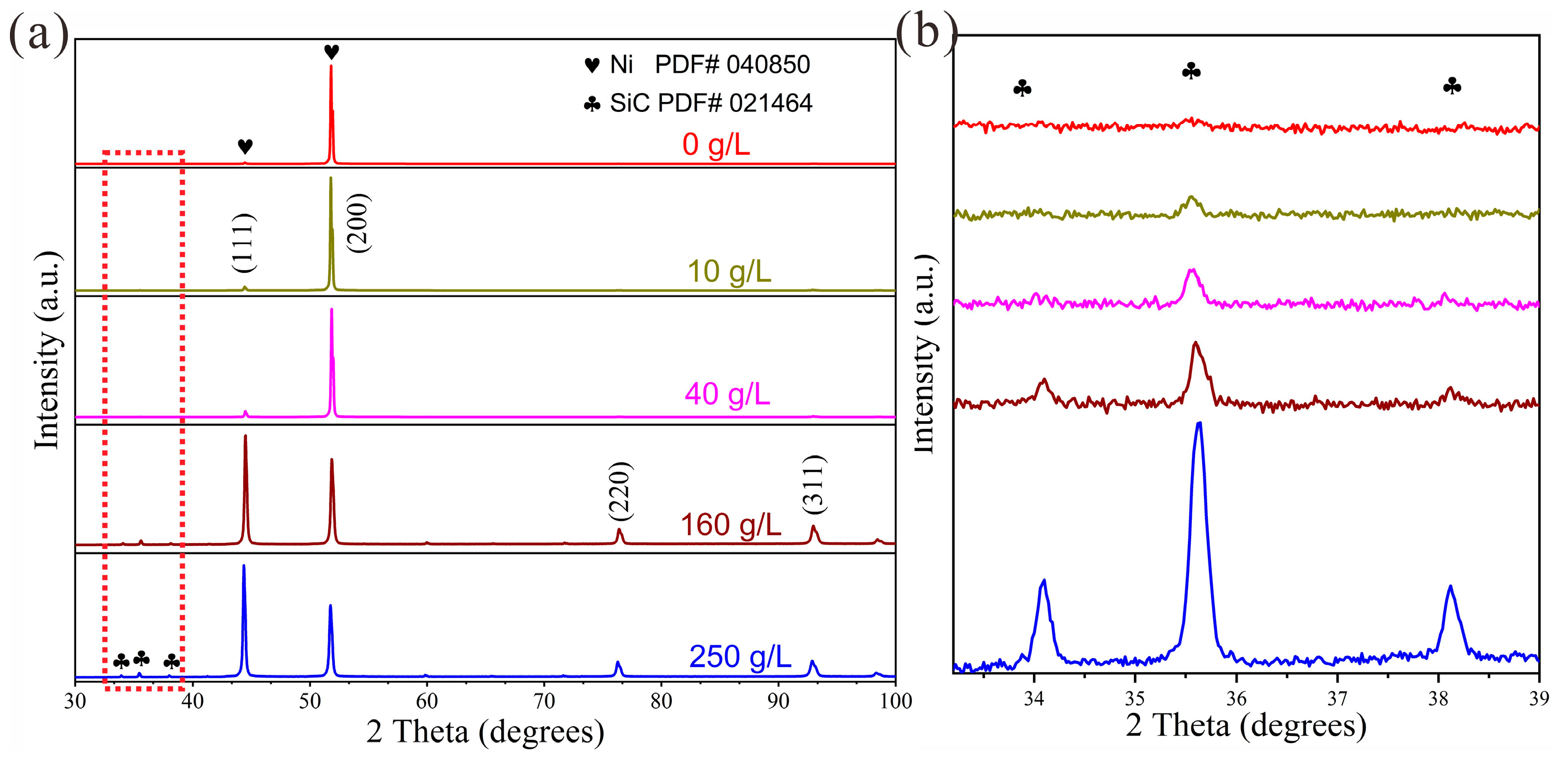
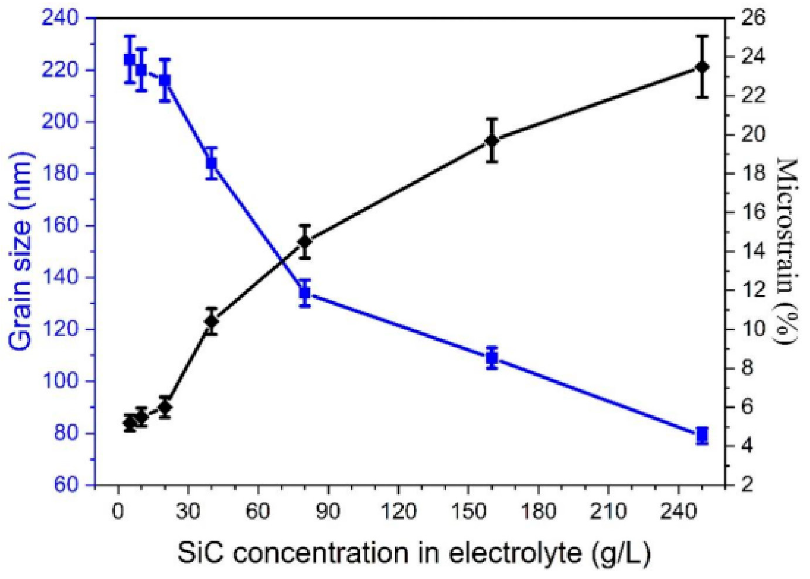
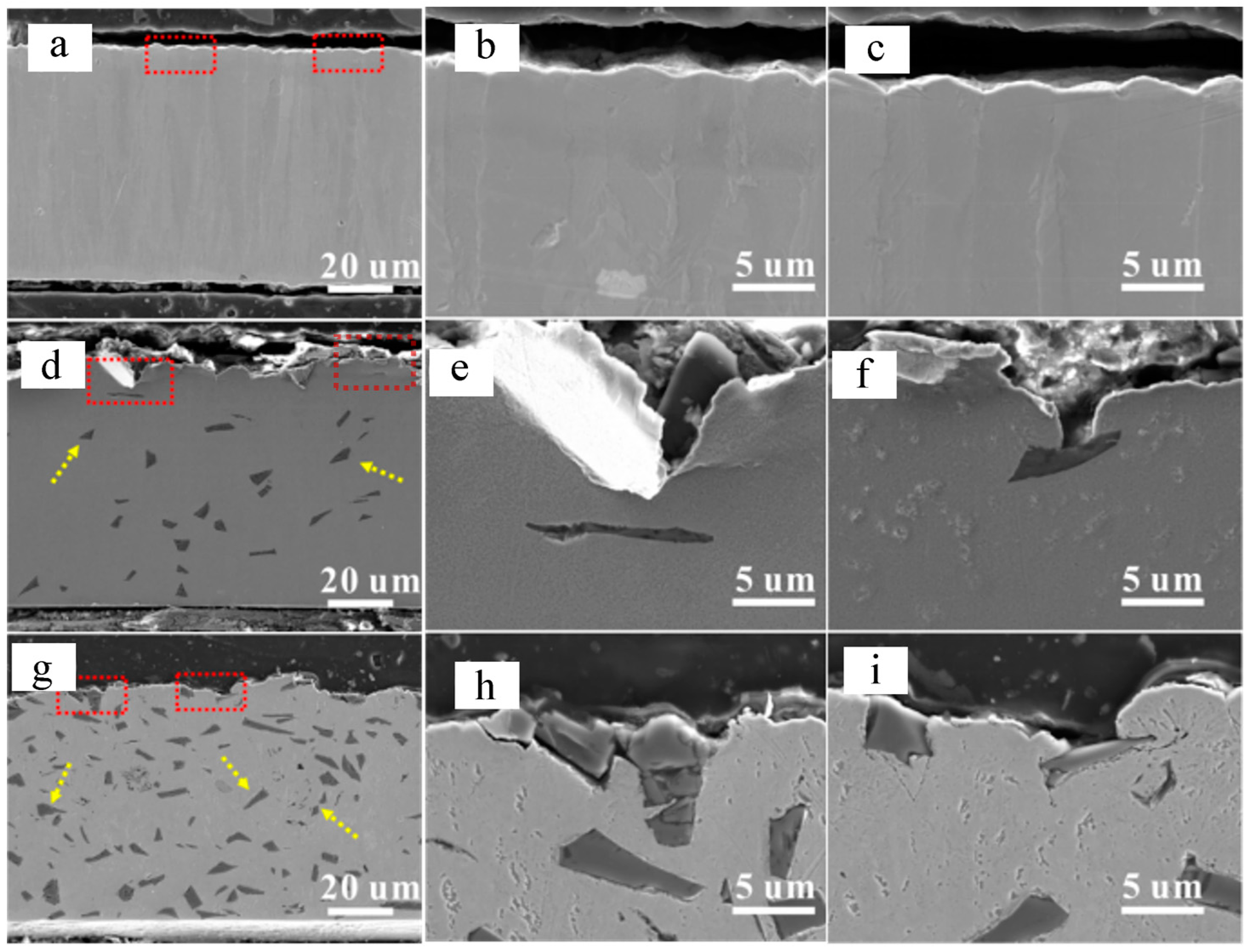
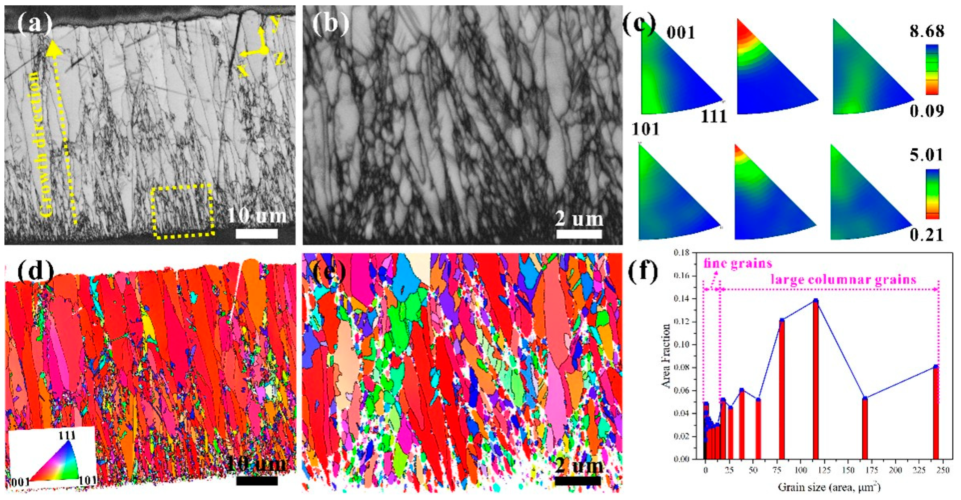
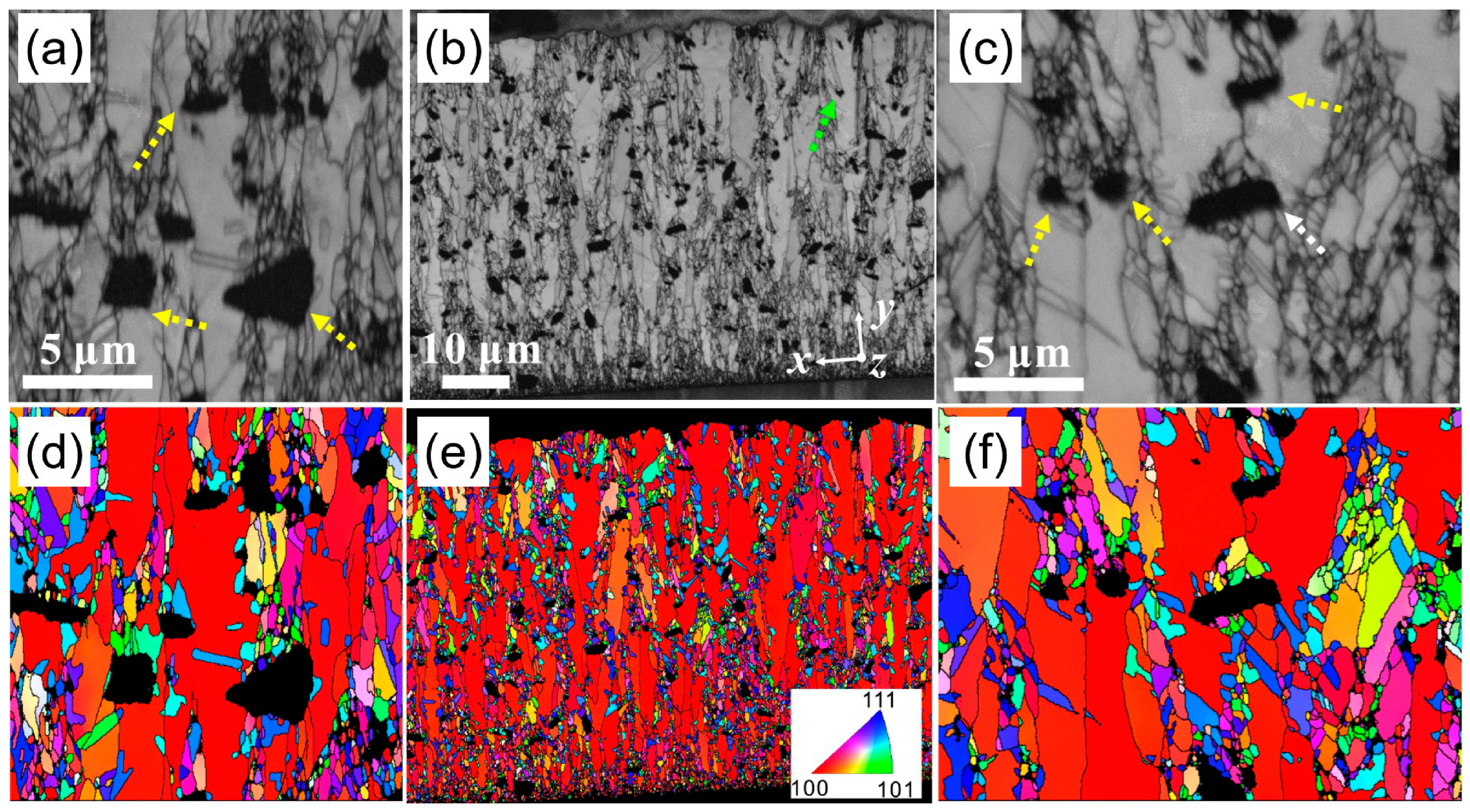
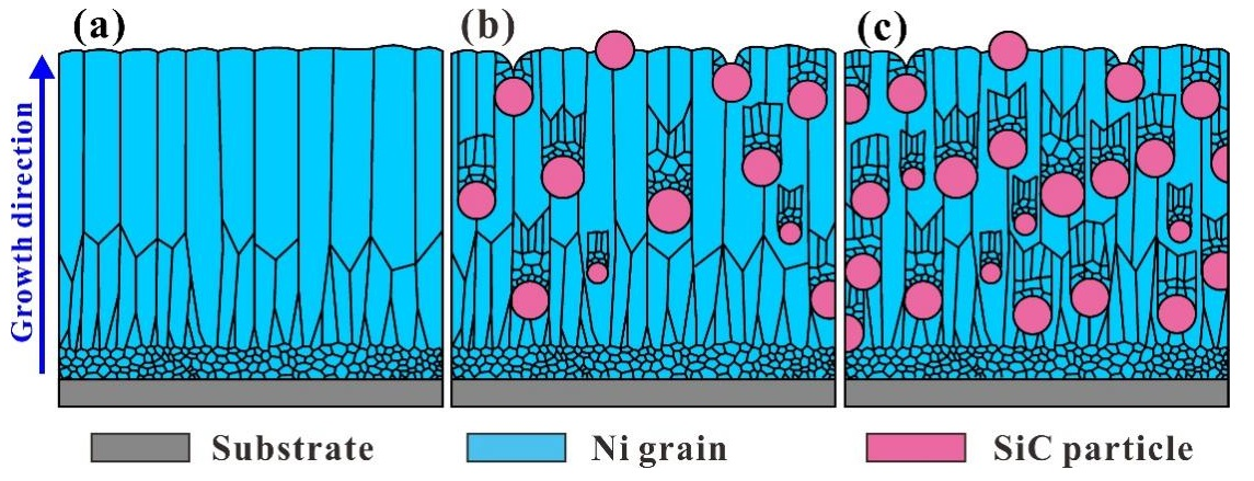
3.1. Microstructure Evolution of the Ni-SiC Composite Coating

XRD patterns were obtained to explore the phase composition of the coatings. As shown in Figure 1, the peaks of the pure Ni coating locating at 44.5°, 51.8°, and 76.3° correspond to the (111), (200), and (220) planes of the Ni phase (PDF# 04-0850), and no other peaks were detected. In addition, the pure Ni coating possesses an ultra-high (200) peak accompanied with a weak (111) peak and (220) peak, illustrating a preferred growth orientation of Ni grains along (200) crystallographic orientation. As for the Ni-SiC composite coating electrodeposited in Watts bath containing 10 g/L of SiC microparticles, apart from the peaks belonging to the Ni phase, a weak peak located at 35.6° is observable, which can be indexed to (1010) plane of the SiC phase (PDF# 22-1316), proving the incorporation of SiC microparticles. The (200) peak is still the highest diffraction peak of the Ni phase. By increasing the concentration of SiC microparticles from 10 g/L to 40 g/L, the (200) peak intensity slightly decreases, while the (111) peak intensity increases, presenting the disturbance of the preferred growth orientation of Ni grain. When the SiC microparticles concentration continues to increase to 160 g/L, the (111) peak surpass the (200) peak, and the (220) peak and the (312) peak become stronger. When further increasing the SiC microparticles concentration to 250 g/L, the (200) peak further declines, presenting the attenuation of a preferred orientation growth of Ni grains along the (200) direction. Figure 1b illustrates the enlarged picture, which is marked out by a red dotted line in Figure 1a. The peaks located at 34.1°, 35.6°, and 38.1° belong to (015), (1010), and (1016) planes of the SiC phase (PDF# 22-1316), respectively. Obviously, the intensity of all the peaks increases by increasing the SiC microparticle concentration, indicating an increased content of SiC microparticle in the Ni-SiC composite coatings.
Figure 2 shows the average grain size and microstrain of the Ni matrix, which are evaluated using the XRD Rietveld method [25,26]. As the concentration of SiC microparticle increases from 0 to 20 g/L, the average grain size slightly decreases from 224 to 216 nm, presenting a weak effect of SiC microparticles at low contents. By increasing the concentration to 40 g/L, the grain size sharply decreases to 184 nm. With a continuing increase in the concentration to 250 g/L, the grain size of the Ni matrix gradually decreases to 82 nm. However, the microstrain of the Ni-SiC composite coating exhibits an inverse variation tendency. The microstrain of the Ni matrix slightly increases with the increase in the SiC concentration, which is mainly correlated with the lattice distortion at the position of defects, the grain boundary, and phase boundary, induced by the incorporation of SiC microparticles [27].
Cross-section views are obtained under the help of SEM. As shown in Figure 3a–c, the pure Ni coating presents a compact and smooth surface morphology with some small bulges. Figure 3d shows the Ni-SiC composite coatings electrodeposited in Watts’ bath containing 40 g/L SiC microparticles. SiC microparticles can be easily identified by their dark grey color, which are pointed out by yellow arrows. With respect to pure Ni coating, the surface morphologies of Ni-SiC composite coatings become rough and uneven due to the presence of some valleys. As shown in Figure 3e,f, the valleys always locate upon the non-fully buried SiC microparticles. As the concentration of SiC microparticles increases to 250 g/L, the content of SiC microparticles in the coatings increases obviously. Interestingly, some captured SiC microparticles constitute some “high spots” (see in Figure 3h). This was because the Ni metal could not directly deposit on the SiC microparticles’ surface due to their non-conductive nature. At the moment of turning off the power, the deposition of the Ni metal stopped immediately, and the deposition did not allow adequate time for the Ni deposits to become thick enough to secure the SiC microparticles. If the power supply was re-turned on, the growth of Ni deposits would proceed, and then the SiC microparticles were fully buried by both lateral sides of the Ni deposits (see in Figure 3i).
Pole figures are obtained to investigate the texture variation in the Ni-SiC composite coatings. As shown in Figure 4a, the pure Ni coating possess a typical strong (200) fiber texture, which has been observed in many research works [28,29]. As shown in Figure 4b, the addition of 10 g/L of SiC microparticles leads to a slight decrease in the (200) fiber texture. As the concentration of SiC microparticles increases to 20 g/L, no obvious changes are observed. When concentration of SiC microparticles keeps increasing to 160 g/L, the level of the (200) fiber texture significantly declines. After further increasing to 250 g/L, a weak (200) fiber texture still exists in the Ni-SiC composite coating. The incorporation of SiC microparticles cannot completely remove the (200) fiber texture from Ni-SiC composite in spite of the content of SiC microparticles reaching a relatively high value.
EBSD were performed to explore the microstructure of the coatings. As shown in Figure 5a, the growth of pure Ni coating starts with fine grains and then elongates as columnar grains emerge as the thickness increases. Figure 5b demonstrates a local enlarged figure of the marked position in Figure 5a. Obviously, a sub-layer of ultra-fine grains is observable at the bottom, which is correlated with the heterogeneous nucleation effect of the steel substrate. As shown in Figure 5d, the vertical columnar grains along (200) crystal orientation prove the preferred oriented growth. Figure 5c demonstrates the inverse pole figures. The pure Ni coating possess an ultra-strong (200) fiber texture, which is in accordance with the result of the XRD pole figures. Besides that, it has to be pointed out that the bottom of the coating presents a weak (200) fiber texture, which is likely due to the presence of the random oriented ultra-fine grains. The evaluated grain size is illustrated in Figure 5f. The distribution range of the grain size widely spread from nano-sized squares to a hundred-microscale square, which can be divided into two regions, including fine grains and large columnar grains (see in Figure 5f). The average grain size of the pure Ni coating is about 245.1 nm.
EBSD was performed to explore the microstructure of the Ni-SiC composite coating. As shown in Figure 6b, the incorporated SiC microparticles stop the growth of columnar grains beneath it (marked out in Figure 6a,c by yellow arrows). However, the columnar grains between the embedded SiC microparticles are not disturbed. An interesting observation is that, when the width of the SiC microparticles is smaller than the width of the Ni columnar grains, the SiC microparticles can be totally swallowed by the large Ni columnar grains (marked out in Figure 6b by green arrows). Besides that, domains consisting of ultra-fine grains located upon the SiC microparticles are inevitable (see in Figure 6a,c, marked by the yellow arrows) regardless of the SiC microparticle’s size. In some cases, ultra-fine grains can be found beneath the SiC microparticles (see in Figure 6c the white arrow); this is likely because the SiC microparticles located in the area of the refined Ni grain belong to the nether SiC microparticles. Based on the above discussion, it can be concluded that only the grains upon SiC microparticles are refined, and the vertical columnar Ni grains reappear as the position departs from the SiC microparticle’s upper surface, indicating the limited grain refinement. Figure 6c,d show the crystal orientation maps of the Ni-SiC composite coating along the coating growth direction (y direction). The growth of undisturbed columnar Ni grains prefers the (200) plane. The inverse pole figures confirm the presence of the (200) fiber texture. The incorporation of SiC microparticle is unable to completely eliminate the preferential growth of Ni grains. The grain size was evaluated using the software of channel 5; the overall average grain size was about 138.5 nm, which was smaller than that of a pure Ni coating, illustrating a grain refinement after the addition of SiC microparticles. Here, it has to be clarified that the estimated grain size of EBSD was larger than that of the XRD Rietveld method because of the anisotropy of the grain profile along different view directions. The grain size estimated by the XRD Rietveld method was based on the top view, while the grain size estimated by EBSD was based on the cross-section view.
Based on the above discussion, the schematic diagram of the microstructure evolution of the Ni-SiC composite coating was established. As shown in Figure 7a, the growth of pure Ni coating starts with Ni nanograins at the substrate surface. As the position departs from the substrate surface, the Ni nanograins are transformed into the elongated columnar Ni grains. With the distance from the substrate increasing, the width of the columnar Ni grains gradually increases and becomes saturated. Figure 7b shows the microstructure of Ni-SiC composite coating with a low content of SiC microparticles. The bottom microstructure of the Ni deposit has no changes despite the incorporation of SiC microparticles, which is similar to the pure Ni coating. The embedded SiC microparticles cut off the continuous growth of Ni columnar grains without disturbing the underneath and lateral Ni grains. A new layer consisting of ultra-fine Ni grains upon SiC microparticle top is formed; the ultra-fine Ni grains evolve into columnar grains with the position departing upper surface of SiC microparticles. If the SiC microparticle size is less than the width of the columnar Ni grains, the small microparticle would be totally implanted into the Ni grains. However, grain refinement upon SiC microparticle was inevitable in spite of small- or large-size SiC particles. Figure 7c illustrates Ni-SiC composite coating with a high content of SiC microparticle. Ni grains were refined, but they did not disturb the elongated columnar Ni grains between the incorporated SiC microparticles. Thus, the (200) fiber texture was observable in the composite coating with a high content of SiC microparticle. Here, we found that only a layer consisting of fine grains was found upon SiC microparticles, which was due to the current density concentration rather than heterogeneous nucleation. The heterogeneous nucleation of Ni grains was not available. Besides that, the Ni deposits could not directly deposit on the surface of the SiC microparticle due to the non-conductivity (see in Figure 7).

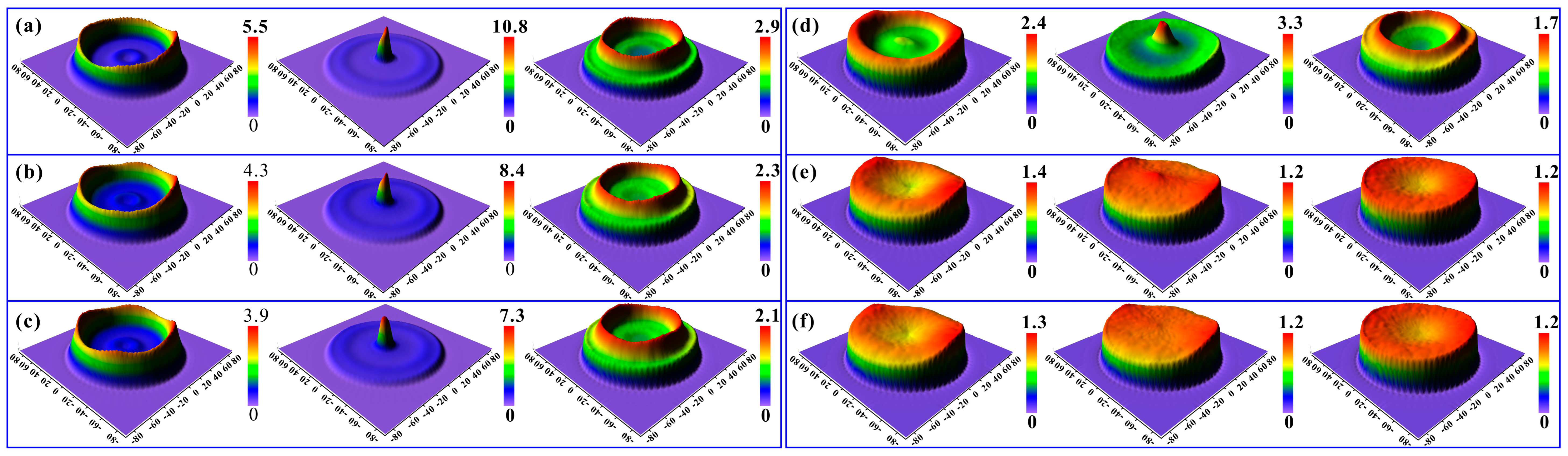
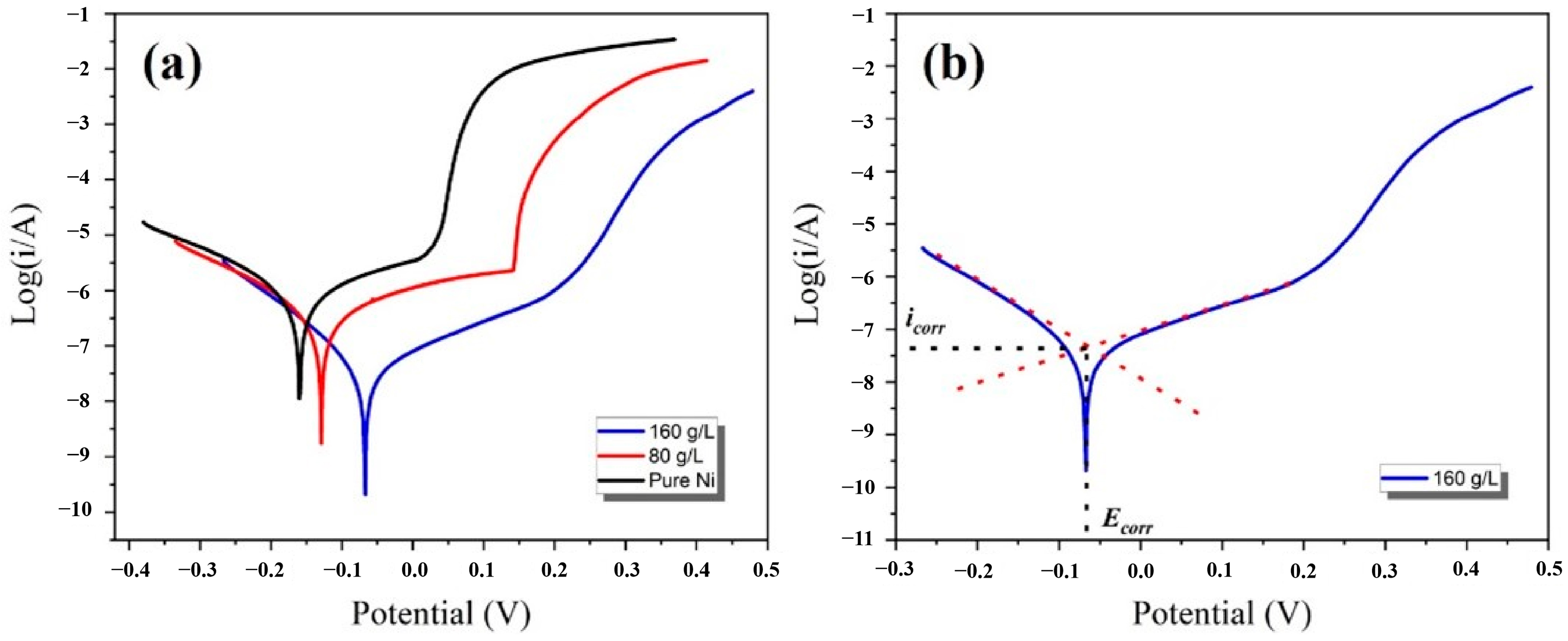
3.2. Corrosion Testing of the Ni-SiC Composite Coating

The corrosion properties were characterized using the electrochemical testing method, which are shown in Figure 8. The corrosion current density (Icorr) and corrosion potential (Ecorr) were calculated using the method of Tafel extrapolation (see in Figure 8b). The Ecorr and Icorr of the pure Ni coating were −0.16 V and 1.09 × 10⁻⁶ A/cm2, respectively. The addition of SiC microparticles (80 g/L) leads to a positive shift of Ecorr to −0.12 V, indicating the increased ability of the resistance to external corrosion. The Icorr declines to 4.79 × 10⁻⁷ A/cm2, representing the reduction in the corrosion rate. With the concentration of SiC microparticles increasing to 250 g/L, Ecorr positively shifts to −0.07 V. The Icorr declines to 4.57 × 10⁻⁶ A/cm2, which was about two orders of magnitude smaller than the that of the pure Ni coating. Two aspects should be taken into consideration, including the effect of SiC microparticles and the tailored microstructure of the Ni matrix. As for the effect of SiC microparticles, the incorporated SiC microparticles disturbed the corrosion path and prolonged the corrosion path [30,31]. Besides that, the presence of anti-corrosion SiC microparticles reduced the contact area between the Ni matrix and aggressive medium [32], reducing the risk of being corroded. Apart from the physical effect, the microstructure evolution of the Ni matrix should take great responsibility for the enhanced corrosion resistance as well. First, the embedded SiC microparticles disturbed the (200) fiber texture of the Ni matrix. Generally, the high-index (200) plane possesses the high dissolution resistance of the surface atoms, which has a negative impact on corrosion resistance [33]. Second, the grain refinement of the Ni matrix brings in plentiful grain boundaries, providing a mass of sits for the simultaneous surface corrosion at different positions. This boosts the homogeneous corrosion rather than the pitting corrosion. Third, the embedded SiC microparticles and the coterminous nickel matrix formed a plentiful “corrosion micro-cell”, favoring the homogeneous corrosion as well [34]. As discussed above, the grain refinement contributed to a homogeneous corrosion and the formation of a uniform passive film on the surface, and the disappearance of the texture of high index planes (200), increased the dissolution resistance of the surface atoms.

4. Conclusions

Ni-SiC composite coatings with different contents of SiC microparticle were assembled via electrodeposition. The increased concentration of SiC microparticles in the Watts bath resulted in an increased content of SiC in the composite coating. The increased content of SiC particles led to the grain refinement and recession of the (200) fiber texture of the Ni deposits. An enhanced corrosion resistance of the Ni-SiC composite coatings was obtained. Three major aspects should be taken into consideration. First, the grain refinement of Ni deposits contributed to homogeneous corrosion; second, the vanishing of easy-corrosive (200) plane; last, the disturbance and extension of the corrosion path.
The role of the SiC microparticle was systematically revealed. The EBSD result showed that the SiC microparticle blocked the underlying columnar Ni grains without disturbing the lateral columnar Ni grains. The columnar Ni grain between the embedded SiC microparticle grew without disturbance. Only upon the SiC microparticles upper surface was a new layer consisting of ultra-fine Ni grains observable, and the vertical columnar Ni grains reappeared as the position departed the SiC microparticles’ upper surface. The incorporated SiC microparticles led to enhanced corrosion properties mainly as a result of optimizing the microstructure of the Ni matrix, such as grain refinement and the elimination of the (200) fiber texture.

Author Contributions

Conceptualization, L.W. and Y.Z.; methodology, G.L.; software, G.L.; validation, G.L., Z.T. and Z.C.; formal analysis, R.T.; investigation, R.T.; resources, Z.C.; data curation, Z.C.; writing—original draft preparation, G.L.; writing—review and editing, W.L.; visualization, Y.L.; supervision, Y.Z.; project administration, W.L.; funding acquisition, Y.Z. All authors have read and agreed to the published version of the manuscript.

Funding

The authors gratefully acknowledge the financial support provided by the Shanghai Sailing Program, China (Grant No. 20YF1416400), Shanghai High-level Local University Innovation Team (Maritime safety & technical support), the Science & Technology Commission of Shanghai Municipality and Shanghai Engineering Research Center of Ship Intelligent Maintenance and Energy Efficiency under (Grant 20DZ2252300).

Institutional Review Board Statement

Not applicable.

Informed Consent Statement

Not applicable.

Data Availability Statement

The raw/processed data required to reproduce these findings cannot be shared at this time as the data also forms part of an ongoing study.

Conflicts of Interest

The authors declare no conflict of interest.

References

  1. Low, C.T.J.; Wills, R.G.A.; Walsh, F.C. Electrodeposition of composite coatings containing nanoparticles in a metal deposit. Surf. Coat. Technol. 2006, 201, 371–383. [Google Scholar] [CrossRef]
  2. Saini, A.; Singh, G.; Mehta, S.; Singh, H.; Dixit, S. A review on mechanical behaviour of electrodeposited NI-composite coatings. Int. J. Interact. Des. Manuf. (IJIDeM) 2022, 16, 1–12. [Google Scholar] [CrossRef]
  3. Wang, L.; Xing, S.; Shen, Z.; Liu, H.; Jiang, C.; Ji, V.; Zhao, Y. The synergistic role of TI microparticles and CEO2 nanoparticles in tailoring microstructures and properties of high-quality Ni matrix nanocomposite coating. J. Mater. Sci. Technol. 2022, 105, 182–193. [Google Scholar] [CrossRef]
  4. Zhang, H.; Wang, J.; Li, Q.; Chen, S.; Ma, C. Microstructure and performance of magnetic field assisted, pulse-electrodeposited Ni–Tin thin coatings with various tin grain sizes. Ceram. Int. 2021, 47, 18532–18539. [Google Scholar] [CrossRef]
  5. Karadag, A.; Duru, E.; Uysal, M.; Akbulut, H.; Coban, A. Tribological performance of Ni-W/PTFE composite coating via pulse electrodeposition. Int. J. Therm. Sci. 2022, 26, 2885–2893. [Google Scholar] [CrossRef]
  6. Ren, L.; Cheng, Y.; Wang, Q.; Yang, J. Study on the properties of Ni-W-P coating with PTFE co-deposition. Surf. Topogr. Metrol. Prop. 2019, 7, 045009. [Google Scholar] [CrossRef]
  7. Wang, L.; Ren, J.; Zhao, Y.; Ji, V.; Liu, H.; Liu, M.; Wang, Z.; Jiang, C.; Wang, Z. Effect of TI microparticles on the microstructure and properties of Ni-Ti composite coating prepared by electrodeposition. J. Alloys Compd. 2022, 908, 164313. [Google Scholar] [CrossRef]
  8. Bazzard, R.; Boden, P.J. Nickel-chromium alloys by Codeposition: Part I—Codeposition of chromium particles in a nickel matrix. Trans. IMF 1972, 50, 63–69. [Google Scholar] [CrossRef]
  9. Bazzard, R.; Boden, P.J. Nickel-chromium alloys by Codeposition: Part II—Diffusion heat treatment of codeposited composites. Trans. IMF 1972, 50, 207–210. [Google Scholar] [CrossRef]
  10. Bratu, F.; Benea, L.; Celis, J.-P. Tribocorrosion behaviour of Ni–SIC composite coatings under lubricated conditions. Surf. Coat. Technol. 2007, 201, 6940–6946. [Google Scholar] [CrossRef]
  11. Aruna, S.T.; Anandan, C.; Grips, V.K.W. Effect of probe sonication and sodium hexametaphosphate on the microhardness and wear behavior of electrodeposited Ni–SIC composite coating. Appl. Surf. Sci. 2014, 301, 383–390. [Google Scholar] [CrossRef]
  12. Zhang, S.; Han, K.; Cheng, L. The effect of sic particles added in electroless Ni–P plating solution on the properties of composite coatings. Surf. Coat. Technol. 2008, 202, 2807–2812. [Google Scholar] [CrossRef]
  13. Lai, L.; Li, H.; Sun, Y.; Ding, G.; Wang, H.; Yang, Z. Investigation of electrodeposition external conditions on morphology and texture of Ni/SICW composite coatings. Appl. Sci. 2019, 9, 3824. [Google Scholar] [CrossRef] [Green Version]
  14. Bandhu, D.; Thakur, A.; Purohit, R.; Verma, R.K.; Abhishek, K. Characterization & Evaluation of AL7075 mmcs reinforced with ceramic particulates and influence of age hardening on their tensile behavior. J. Mech. Sci. Technol. 2018, 32, 3123–3128. [Google Scholar] [CrossRef]
  15. Cao, M.; Yue, Y.; Guo, X.; Wang, B. Effects of SiC Particle Concentration on the Ultrasonic-Assisted Jet Electrodeposited Ni-SiC Nanocoatings. Int. J. Electrochem. Sci. 2022, 17, 220113. [Google Scholar] [CrossRef]
  16. Li, C.; Xia, F.; Ma, C.; Li, Q. Research on the corrosion behavior of Ni-SIC nanocoating prepared using a jet electrodeposition technique. J. Mater. Eng. Perform. 2021, 30, 6336–6344. [Google Scholar] [CrossRef]
  17. Ma, C.; Liang, G.; Zhu, Y.; Mu, H.; Xia, F. Preparation and corrosion assessment of electrodeposited Ni–SIC composite thin films. Ceram. Int. 2014, 40, 3341–3346. [Google Scholar] [CrossRef]
  18. Zhang, H.; Wang, J.; Chen, S.; Wang, H.; He, Y.; Ma, C. Ni–SIC composite coatings with improved wear and corrosion resistance synthesized via ultrasonic electrodeposition. Ceram. Int. 2021, 47, 9437–9446. [Google Scholar] [CrossRef]
  19. Garcia, I.; Fransaer, J.; Celis, J.-P. Electrodeposition and sliding wear resistance of nickel composite coatings containing micron and submicron SIC particles. Surf. Coat. Technol. 2001, 148, 171–178. [Google Scholar] [CrossRef]
  20. Lee, H.-K.; Lee, H.-Y.; Jeon, J.-M. Codeposition of micro- and nano-sized SIC particles in the nickel matrix composite coatings obtained by electroplating. Surf. Coat. Technol. 2007, 201, 4711–4717. [Google Scholar] [CrossRef]
  21. Watson, S.W. Electrochemical study of SIC particle occlusion during nickel electrodeposition. J. Electrochem. Soc. 1993, 140, 2235–2238. [Google Scholar] [CrossRef]
  22. Abi-Akar, H.; Riley, C.; Maybee, G. Electrocodeposition of nickel–diamond and cobalt–chromium carbide in low gravity. Chem. Mater. 1996, 8, 2601–2610. [Google Scholar] [CrossRef]
  23. Stappers, L.; Fransaer, J. Growth of metal around particles during electrodeposition. J. Electrochem. Soc. 2006, 153, C472. [Google Scholar] [CrossRef]
  24. Lampke, T.; Wielage, B.; Dietrich, D.; Leopold, A. Details of crystalline growth in co-deposited electroplated nickel films with hard (nano)particles. Appl. Surf. Sci. 2006, 253, 2399–2408. [Google Scholar] [CrossRef]
  25. Zhao, Y.; Jiang, C.; Xu, Z.; Cai, F.; Zhang, Z.; Fu, P. Microstructure and corrosion behavior of Ti nanoparticles reinforced Ni–Ti composite coatings by electrodeposition. Mater. Des. 2015, 85, 39–46. [Google Scholar] [CrossRef]
  26. Naji, H.; Khalil-Allafi, J.; Khalili, V. Microstructural characterization and quantitative phase analysis of Ni-rich Niti after stress assisted aging for long times using the Rietveld method. Mater. Chem. Phys. 2020, 241, 122317. [Google Scholar] [CrossRef]
  27. Wang, L.; Zhao, Y.; Jiang, C.; Ji, V.; Chen, M.; Zhan, K.; Moreira, F. Investigation on microstructure and properties of electrodeposited Ni-Ti-CEO2 composite coating. J. Alloys Compd. 2018, 754, 93–104. [Google Scholar] [CrossRef]
  28. Maharana, H.S.; Bishoyi, B.; Basu, A. Current density dependent microstructure and texture evolution and related effects on properties of electrodeposited Ni-Al Coating. J. Alloys Compd. 2019, 787, 483–494. [Google Scholar] [CrossRef]
  29. Chhangani, S.; Prasad, M.J.N.V. Microstructure, texture and tensile behavior of pulsed electrodeposited Ni–Al Composites produced using organic additive-free sulfamate bath loaded with al nanoparticles. Mater. Charact. 2018, 136, 247–256. [Google Scholar] [CrossRef]
  30. Vaezi, M.R.; Sadrnezhaad, S.K.; Nikzad, L. Electrodeposition of Ni–SIC nano-composite coatings and evaluation of wear and corrosion resistance and electroplating characteristics. Colloids Surf. A Physicochem. Eng. Asp. 2008, 315, 176–182. [Google Scholar] [CrossRef]
  31. Garcia, I.; Conde, A.; Langelaan, G.; Fransaer, J.; Celis, J.P. Improved corrosion resistance through microstructural modifications induced by codepositing SIC-particles with electrolytic nickel. Corros. Sci. 2003, 45, 1173–1189. [Google Scholar] [CrossRef]
  32. Jiang, W.; Shen, L.; Qiu, M.; Xu, M.; Tian, Z. Microhardness, wear, and corrosion resistance of Ni–SIC composite coating with magnetic-field-assisted jet electrodeposition. Mater. Res. Express 2018, 5, 096407. [Google Scholar] [CrossRef]
  33. Wang, L.; Chen, M.; Liu, H.; Jiang, C.; Ji, V.; Moreira, F. Optimisation of microstructure and corrosion resistance of Ni-Ti composite coatings by the addition of CEO2 nanoparticles. Surf. Coat. Technol. 2017, 331, 196–205. [Google Scholar] [CrossRef]
  34. Zhou, Y.B.; Sun, J.F.; Wang, S.C.; Zhang, H.J. Oxidation of an electrodeposited Ni–Y2O3 composite film. Corros. Sci. 2012, 63, 351–357. [Google Scholar] [CrossRef]
Figure 1. (a) XRD patterns of Ni-SiC coatings electrodeposited from Watts solution containing various concentrations of SiC particles, and (b) the magnified images of area marked by the red dotted line.
Coatings 13 00695 g001
Figure 2. Grain size and microstrain distribution of Ni matrix with various concentrations of SiC particle concentrations.
Coatings 13 00695 g002
Figure 3. SEM cross-section view of (a) pure Ni coating and Ni-SiC composite coatings electrodeposited in Watts bath containing (d) 40 and (g) 250 g/L SiC microparticles; (b,c,e,f,h,i) enlarge pictures of the red dot line marked positions in (a,d,g). Figure 3f is out of the visual field in Figure 3d.
Coatings 13 00695 g003
Figure 4. Pole figures of the Ni-SiC composite coatings assembled from Watts’ bath with (a) 0, (b) 10, (c) 20, (d) 80, (e) 160, and (f) 250 g/L SiC microparticles.
Coatings 13 00695 g004
Figure 5. Band contrast maps of (a) whole pure Ni coating, and (b) local enlarged area near the substrate as marked by the yellow dotted lines in (a); (d,e) crystal orientation maps corresponding to (a,b); (c) up and down inverse pole figures corresponding to (a,b); (f) grain size distribution of the whole pure Ni coating.
Coatings 13 00695 g005
Figure 6. (ac) EBSD band contrast maps of Ni-SiC composite coating; (a,c) enlarged images of (b); (df) corresponding crystal orientation maps. The colorful arrows in the figures represent the co-deposited SiC particles.
Coatings 13 00695 g006
Figure 7. Schematic diagrams of the coating microstructure: (a) pure Ni coating; Ni-SiC composite coating contains low content (b) and high content (c) of SiC microparticles.
Coatings 13 00695 g007
Figure 8. (a) Tafel plots of the composite coatings; (b) diagram of Tafel extrapolation method.
Coatings 13 00695 g008
Disclaimer/Publisher’s Note: The statements, opinions and data contained in all publications are solely those of the individual author(s) and contributor(s) and not of MDPI and/or the editor(s). MDPI and/or the editor(s) disclaim responsibility for any injury to people or property resulting from any ideas, methods, instructions or products referred to in the content.

