Article

Titanium Implant Alloy Modified by Electrochemically Deposited Functional Bioactive Calcium Phosphate Coatings

1
Department of Electrochemistry, Faculty of Chemical Engineering and Technology, University of Zagreb, Marulićev trg 19, 10000 Zagreb, Croatia
2
Division of Materials Chemistry, Ruđer Bošković Institute, Bijenička Cesta 54, 10002 Zagreb, Croatia
*
Author to whom correspondence should be addressed.
Coatings 2023, 13(3), 640; https://doi.org/10.3390/coatings13030640
Submission received: 23 February 2023 / Revised: 14 March 2023 / Accepted: 15 March 2023 / Published: 17 March 2023
(This article belongs to the Special Issue Biomimetic Approaches in Coatings Synthesis)

Abstract

:
Calcium phosphate-based (CaP) bioceramic materials are widely used in the field of bone regeneration, both in orthopaedics and in dentistry, due to their good biocompatibility, osseointegration and osteoconduction. The formation of CaP coatings on high-strength implant materials such as titanium alloys combines the superior mechanical properties of metals with the osteoconductive properties of CaP materials. In this work, the electrochemically assisted deposition of CaP coatings on the titanium alloy, TiAlNb, which is commonly used commercially as an implant material in orthopaedic devices, was examined. The barrier properties (electronic properties) of unmodified and CaP-modified titanium alloy were tested in situ in a simulated physiological solution, Hanks’ solution, under in vitro conditions of real implant applications using electrochemical impedance spectroscopy (EIS). The morphology and microstructure of the obtained CaP deposit were characterised by scanning electron microscopy (SEM) and chemical composition was assessed by energy dispersive X-ray spectroscopy (EDS) and attenuated total reflection Fourier transform infrared spectroscopy (ATR-FTIR). The aim was to investigate the effect of calcium phosphate CaP coating on the corrosion resistance of the titanium TiAlNb alloy and to understand better the deposition process in the production of bioactive functional coatings on metallic implant materials.

1. Introduction

Longer life expectancy and increasing demands on people’s quality of life have led to the increasing importance of implant materials, of which metals are the most commonly used [1,2,3,4]. The domination of titanium and its alloys, especially in dentistry and orthopaedics, is due to their physical, chemical, and mechanical properties [5,6,7,8]. The most commonly used titanium alloy is Ti6Al4V alloy, which is characterised by excellent mechanical strength [7,9]. However, the release of potentially harmful metal ions and their accumulation in body organs is of great concern, as vanadium is known for its cytotoxic effects, which can suppress cell growth and induce oxidative stress [10,11]. Therefore, Ti6Al7Nb alloy that contains less toxic, non-harmful Nb and meets the requirements for orthopaedic applications has been recently used [12,13,14]. These requirements include good biocompatibility, mechanical strength, stiffness, durability, corrosion resistance, and properties important for load-bearing applications (low elastic modulus and good fatigue resistance) [6,15,16]. Commercial medical applications of Ti6Al7Nb alloy for implants include femoral hip stems, fracture fixation plates, spinal components, fasteners, rods, screws, and wires [5,16,17].
While the microstructure of alloy determines its load-bearing properties [6,16], the biological properties of titanium-based materials are governed by their surface chemistry and corrosion behaviour [8,9,18,19]. As the biological environment is considered to be extremely aggressive, corrosion of metallic implant materials occurs, which may cause inflammation or allergic reactions while compromising the implant material’s functions [18,19,20,21,22]. However, under biological conditions, titanium-based materials spontaneously undergo a passivation reaction, forming a few nm thin oxide layer (TiO2) [2,17,19,23]. Titanium(IV) oxide is a semiconductor with high corrosion resistance, attributed to a low density of electron donors [1,3,8,23]. Since titanium alloys are resistant to corrosion reactions in a biological medium, they are therefore considered very biocompatible [3,5,8,17]. However, no bond develops between the metal and the living bone after implementation, so titanium-based alloys are classified as bioinert materials [5,7,8].
In order to achieve bioactivity, which is crucial for the integrity and structural continuity of the implant material with the surrounding bone, surface modification of the implant material is required [9,24,25,26]. Calcium phosphate-based (CaP) bioceramic materials are commonly used as coating agents on titanium-based implant materials to enhance bone apposition and osseointegration [17,27,28,29,30]. Osteoconductivity occurs via direct anchorage of implants by inducing the formation of thin new surrounding bone, i.e., the process is based on a similarity between the bone surface and the CaP material [15,24,31,32]. CaP as artificially produced materials mimic the surface layer of human bone [28,33], which is from the chemical point of view, hydroxyapatite non-stoichiometrically substituted with carbonate, magnesium, and sodium ions [32,33,34,35]. CaP materials include hydroxyapatite (HA, Ca10(PO4)6(OH)2), brushite (DCPD, dicalcium phosphate dihydrate, CaHPO4 × 2H2O), β-tricalcium phosphate (β-TCP, Ca3(PO4)2), octacalcium phosphate (OCP, Ca8(HPO4)2(PO4)4 × 5H2O), and amorphous calcium phosphate (ACP) [28,33,34]. A critical problem limiting the wider clinical application of CaPs is their mechanical properties [36]. In spite of desirable bioactive properties, CaP biomaterials exhibit high brittleness, low impact resistance and relatively low tensile stress and are not suitable for load-bearing areas [30,32,36,37].
By using CaP in the form of coatings on high-strength implant materials such as titanium alloys, one can combine the superior mechanical properties of metals with the osteoinductive properties of CaP materials [15,27,30,32,37].
However, for a successful application, CaP coatings must also meet certain mechanical properties, which, like the physical and chemical properties, depend on the synthetic process, but also on thickness, phase and chemical purity, fatigue strength, porosity, adhesion, and abrasion resistance [24,27,30,38]. Although the mechanical properties have been the subject of extensive research, the results are not fully comparable because the coatings were produced on different substrates, using different techniques and under different synthesis conditions (addition of additives and pre- and post-treatments) [28,34]. Therefore, it is necessary to continue research and optimise them [28,39,40].
CaP coatings on titanium/titanium alloys can be formed by various methods, including electrocrystallisation, biomimetic processes, plasma or thermal spraying, polymeric route, electrophoretic deposition, sol–gel, sputtering, etc. [27,28,30,41,42,43,44]. Nowadays, electrochemically assisted deposition (ED) of calcium phosphates on titanium/titanium alloys [45,46,47,48] is gaining a lot of attention due to its advantages compared to other conventional methods, such as plasma spraying [17,30,49,50,51]. Low-temperature deposition allows the formation of highly crystalline deposits with low residual stresses and low solubility in body fluids [28,30,50]. Moreover, since it is a line-of-sight technique, it is applicable to porous and geometrically complex surfaces [28,30,51,52]. Suitable process conditions can be used to control the thickness, composition, and microstructure of the deposit [30,50,51]. Finally, the low cost of equipment makes electrodeposition economically affordable [50,51,52].
The CaP properties, in particular the surface properties, affect the cascade of biological processes (protein adsorption, cell adhesion, and cell differentiation) [30]. It is generally reported that rougher surfaces are very beneficial for the attachment of bone cells [28,30,53]. Crystal sizes and shapes also play a crucial role in biological responses [54]. CaPs with specific nano-/micro-structures can better mimic the biomimetic features of human bones and teeth [29,31,35,54]. The synthesis of CaPs with controllable size and size distribution, crystal shape and aggregation, and specific structural characteristics is the key step, which is still a major challenge due to the significant differences in chemical composition, crystallographic structure, crystallisation thermodynamics and kinetics, phase stability and dissolution behaviour of different CaPs [27,28,53,54,55]. In this work, the electrochemically assisted deposition of calcium phosphate (CaP) coatings on the titanium alloy, Ti6Al7Nb, was investigated. The barrier properties (electronic properties) of the unmodified and the CaP-modified titanium alloy were tested in situ in a simulated physiological solution, Hanks’ solution, under in vitro conditions of real implant applications, using electrochemical impedance spectroscopy (EIS). The electrochemical behaviour and corrosion parameters were also investigated by linear polarisation measurements (the LPR method and the Tafel extrapolation method). The morphology and microstructure of the obtained CaP deposit were characterised by scanning electron microscopy (SEM) and the chemical composition was studied by energy dispersive X-ray spectroscopy (EDS) and attenuated total reflection Fourier transform infrared spectroscopy (ATR-FTIR). The focus of this work was to optimise the electrodeposition conditions to form the compact functional CaP coating that improves the corrosion resistance of the underlying titanium alloy while contributing to enhanced biocompatibility and bioactivity. In situ investigations carried out under in vitro conditions provide useful information and further insight towards the understanding of the electrodeposition mechanism and implant surface functionalisation.

2. Materials and Methods

2.1. Materials

The Ti6Al7Nb (TiAlNb) sheets (Goodfellow Cambridge Ltd., Huntingdon, England, UK), composed according to the ISO standard ISO 5832-11:2014 [56], were cut in 11 mm circular-shaped discs. Before coating, the TiAlNb samples were abraded using SiC #240-#600 grit papers and then ultrasonically cleaned in absolute ethanol (p.a, Gram-Mol®, Zagreb, Croatia) and redistilled water (18 MΩ cm) and dried in pure N2 stream (99.999%, Messer®, Bad Soden, Germany). The TiAlNb samples prepared in this way represented unmodified electrodes (referred to as TiAlNb unmodified) and served as substrates for the deposition of the calcium phosphate coating.

2.2. Coating Preparation

The cathodically assisted deposition of the calcium phosphate coating (CaP) on TiAlNb substrates was carried out in an aqueous solution of 0.1 mol dm−3 Ca(NO3)2 (p.a., 99%, T.T.T d.o.o., Zagreb, Croatia) and 0.06 mol dm−3 NH4H2PO4 (p.a., 99%, VWR Chemicals, Wien, Austria), pH 4.32. During the deposition, the electrolyte solution was mixed using a magnetic mixer to ensure a uniform concentration of Ca2+ and H2PO4 ions.
Solartron 1287 potentiostat/galvanostat with Solartron FRA 1260 (Solartron Analytical, Farnborough, UK) with an electrochemical three-electrode reactor Corrosion Cell System Model K47 Princeton Applied Research (PAR, Ametek, Berwyn, PA, USA) was used for electrodeposition. The TiAlNb substrates were placed in a Teflon holder with 1 cm2 area exposed to the electrolyte solution. Two graphite rods served as counter electrodes and the reference electrode, to which all potentials in the article refer, was an Ag|AgCl, 3.0 mol dm−3 KCl (E = 0.210 V vs. standard hydrogen electrode) (Metrohm Autolab, Utrecht, Netherlands).
In order to define the electrodeposition process parameters, the cyclic voltammetry measurements were carried out in the electrodeposition solution in the potential range from open circuit potential, Eoc to −3 V vs. Ag|AgCl, at scan rate, v = 10 mV s−1. Based on the cyclic voltammetry results, the electrodeposition potentials (Eed) were obtained, and the electrodeposition process was performed potentiostatically at −2.00 V and at −1.75 V vs. Ag|AgCl for 1 h, designating the samples as TiAlNb|CaP −2.0 V and TiAlNb|CaP −1.75 V, respectively. After coating, the TiAlNb samples were rinsed in redistilled water and dried in a pure nitrogen stream.

2.3. Coatings Characterisation Methods

Electrochemical methods—Electrochemical characterisation of the TiAlNb substrates was carried out in simulated body fluid, Hanks’ solution [23] before and after the coating deposition. Linear polarisation (LP) measurements were carried out in the narrow (±20 mV vs. open circuit potential) and in the wide potential range (±200 mV vs. open circuit potential) at a scan rate of 0.1667 mV s−1. The barrier properties and corrosion resistance of the TiAlNb substrates were tested using electrochemical impedance spectroscopy (EIS). Measurements were performed at open circuit potential, Eoc in the frequency range of 105 to 10−3 Hz with an ac voltage amplitude of ±5 mV after 1 h of stabilisation at Eoc. The impedance data were fitted by a suitable electrical equivalent circuit (EEC) model using complex non-linear least squares (CNLS) fit analysis [57]. Zview® software (v. 3.5e, Scribner Associates Inc., Southern Pines, NC, USA) fit was carried out to model all experimental data with chi-squared values less than 5 × 10⁻³ (relative errors in parameter values less than 5%) indicating that the agreement between the proposed EEC model and the experimental data was good.
Structural characterisation—The morphology/microstructure and chemical composition of the electrodeposited coating were characterised by scanning electron microscopy (SEM) and energy-dispersive X-ray spectroscopy (EDS). Surface imaging of the samples was performed on Axia ChemiSEM electron microscope (Thermo Fisher Scientific Inc, Waltham, MA, USA) using 5 kV and 10 kV electron beams at various magnifications ranging from 50× to 10,000×. The chemical composition of the samples was characterised by an SEM-integrated 70 mm2 SDD (EDS) detector with Peltier cooling system using 10 kV electron beam at 200× (analytical surface area of 640 × 450 μm) and 500× (analytical surface area of 256 × 180 μm) magnification.
The chemical composition of the electrodeposited coatings was determined by attenuated total reflection Fourier transform infrared spectroscopy (ATR-FTIR). The spectra were recorded with the Shimadzu IRTracer-100 spectrometer (Shimadzu, Kyoto, Japan) during 45 cycles in the range of 4000 to 450 cm−1 with a scan resolution of 4 cm−1.
The experiments described in the experimental section were performed on at least three samples, i.e., five samples were tested in the case of deviations. A flow chart of sample preparation and characterisation is shown in Figure 1.

3. Results and Discussion

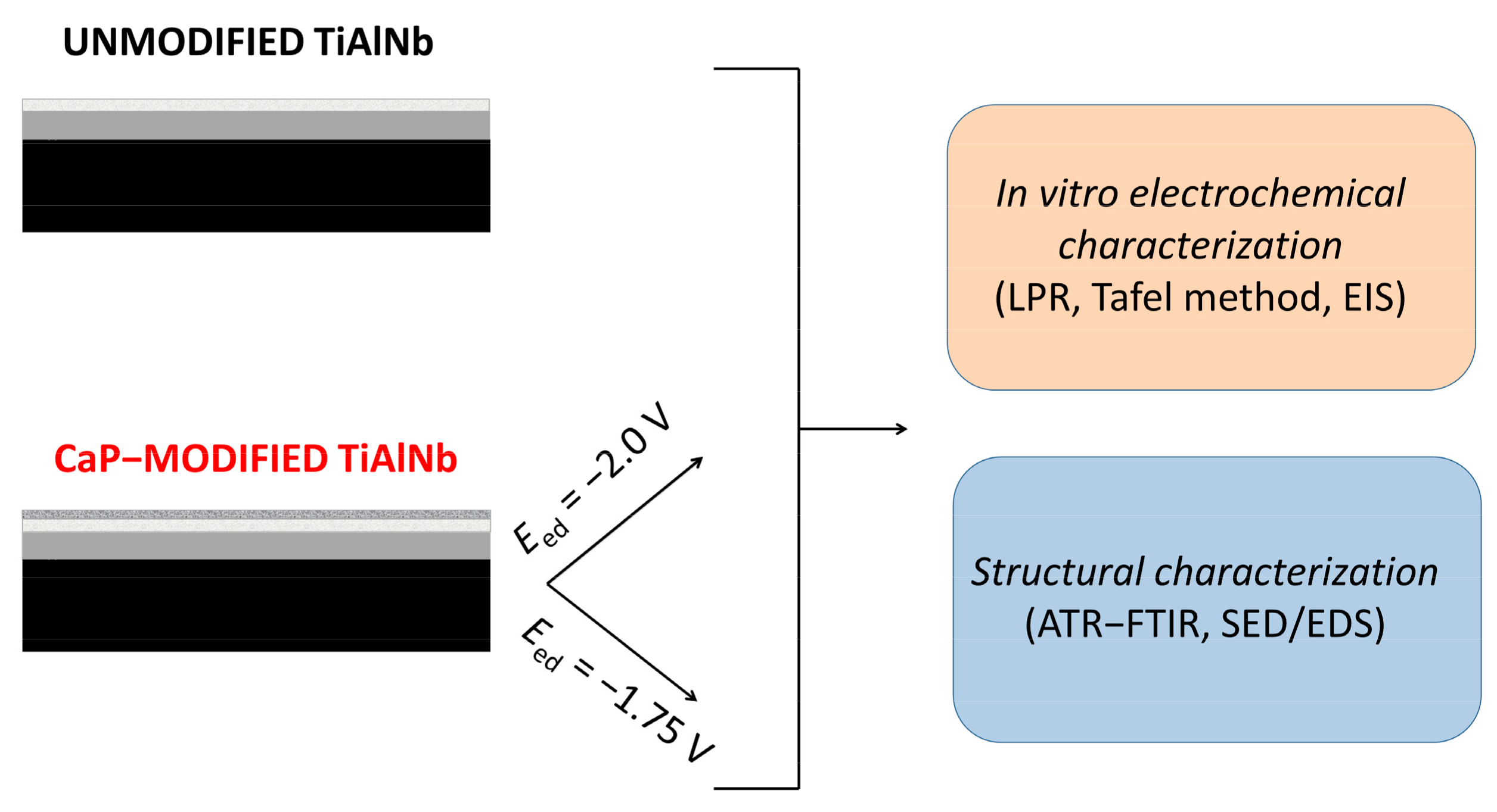
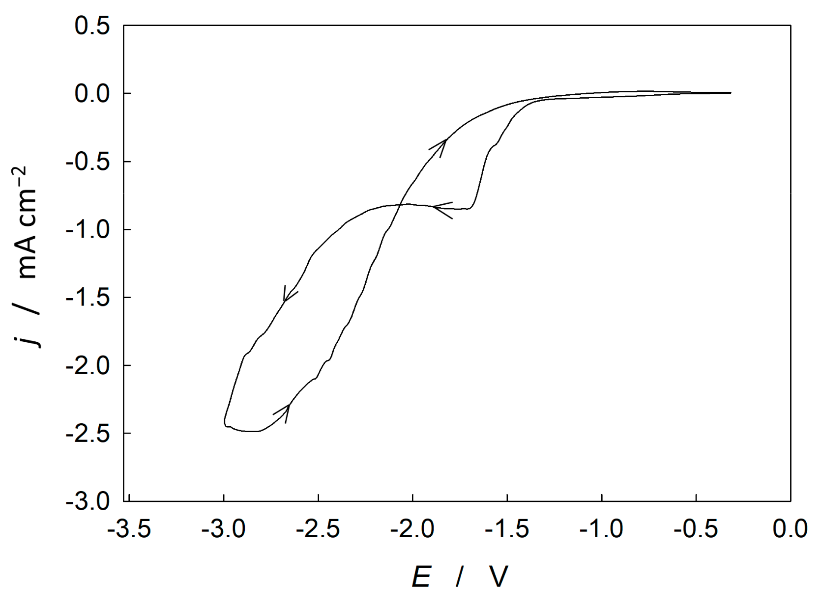
3.1. Electrochemically Assisted Deposition Method for Preparation of Calcium Phosphate Coatings on Titanium Alloy

To determine the coating’s deposition process conditions/parameters, cyclic voltammetry (CV) was employed. CV measurements were performed in a wide potential range, from open circuit potential, Eoc to −3 V vs. Ag|AgCl, at scan rate, v = 10 mV s−1. Measurements were performed in the deposition electrolyte solution consisting of 0.1 mol dm−3 Ca(NO3)2 and 0.06 mol dm−3 NH4H2PO4, pH 4.32. To avoid Ca2+ and H2PO4 ions concentration gradients during the deposition process, the electrolyte solution was constantly stirred during the measurements.
Figure 2 shows the cyclic voltammogram for the TiAlNb alloy displaying a cathodic plateau between −1.6 and −2.3 V. The area of a constant current response indicates the formation and thickening of the calcium phosphate deposit. A sharp increase in the cathodic current response between −2.3 V and −3 V is due to the hydrogen evolution reaction. In the reverse part of the curve, the current response forms a loop, which is typical for nucleation processes on the surface of the working electrode (implant material) [43].
Based on the cyclic voltammetry results, the electrochemically assisted deposition method was carried out at two different deposition potentials, Eed equal to −1.75 V and −2.0 V with obtained samples labelled TiAlNb|CaP −1.75 V and TiAlNb|CaP −2.0 V, respectively.
During the electrodeposition, the titanium alloy is immersed in an aqueous solution of calcium and dihydrogen/hydrogen phosphate ions and is directly electrified, which enables electron and ion transfer reactions. Thus, the following cathodic reactions (and chemical reactions) take place on the surface of the titanium alloy [17,30,50,51]:
O 2 + 2 H 2 O + 4 e 4 OH
2   H 2 PO 4 + 2 e 2   HPO 4 2 + H 2
2 H 2 O + 2 e H 2 + 2 OH
H 2 PO 4 + OH HPO 4 2 + H 2 O
HPO 4 2 + OH PO 4 3 + H 2 O
Ca 2 + +   HPO 4 2 + 2 H 2 O CaHPO 4 × 2 H 2 O
3 Ca 2 + + 2 PO 4 3 Ca 3 PO 4 2
8 Ca 2 + + 2 HPO 4 2 + 4 PO 4 3 + 5 H 2 O Ca 8 HPO 4 2 PO 4 4 × 5 H 2 O
10 Ca 2 + + 6 PO 4 3 + 2 OH Ca 10 PO 4 6 OH 2
Ca 8 HPO 4 2 PO 4 4 × 5 H 2 O + 2   Ca 2 + Ca 10 PO 4 6 OH 2 + 3 H 2 O + 4   H +
10   CaHPO 4 × 2 H 2 O + 12   OH Ca 10 PO 4 6 OH 2 + 4   PO 4 3 + 30   H 2 O
At cathodic potentials, oxygen reduction occurs leading to the formation of OH ions as key electrolyte ions for the CaP electrodeposition process, reaction (1). With further cathodic polarisation, electron transfer promotes the dissociation of dihydrogen phosphate ions to hydrogen phosphate ions, reaction (2). Additionally, at more cathodic potentials, the formation of OH ions due to water reduction (reaction (3), leads to the deprotonation of (di)hydrogen phosphate ions via acid-base reactions (4) and (5). At the same time, calcium ions from the stirred electrodeposition solution migrate to the electrode surface and the cathodic Ti alloy substrate and interact with the (hydrogen) phosphate ions. Several CaP phases can precipitate, reactions (6)–(10), where brushite (CaHPO4 × 2H2O), β-tricalcium phosphate (β-Ca3(PO4)2) and octacalcium phosphate (Ca8(HPO4)2(PO4)4 × 5H2O) are the precursors of the more stable phase hydroxyapatite (Ca10(PO4)6(OH)2) [30,48,51].
The increased concentrations of Ca2+, PO43–, and OH ions near the cathode lead to local solution supersaturation and the pH increase in the surrounding fluid can enhance the apatite ions’ activity [17,47]. After the solution supersaturation reaches the critical value, precipitate crystals grow on the cathode [51], forming a CaP deposit as clearly seen from the cathodic plateau between −1.6 V and −2.3 V (Figure 2) and in the SEM images as will be discussed later.
In addition, a sufficient pH increase in the electrode surface vicinity upon the formation of OH ions enables solid–solid transformation and growth of hydroxyapatite, reaction (11). Brushite (DCPD), β-tricalcium phosphate (TCP), octacalcium phosphate (OCP) and hydroxyapatite (HA) are some known calcium phosphates found in bone [27,32,34]. The CaP electrodeposition involves acid–base reactions facilitated by the local pH increase (due to cathodic polarisation) and precipitation in solution following the decrease in the solubility of the apatite phase when the local pH is increased (due to cathodic polarisation) [30]. The process also includes precipitation in solution due to the direct production of sufficient phosphate ions by electrochemical reactions at adequate cathodic potentials [30].
As already mentioned, the electrolysis of water provides the hydroxyl group needed for the formation of calcium phosphate (CaP) deposits. However, simultaneously generated hydrogen bubbles absorb over the working electrode (implant material). Therefore, when performing the electrochemically assisted deposition at the more cathodic potentials (−2 V vs. −1.75 V), more intense H2 bubble development was observed. The evolution of a large amount of H2 can lead to loose and porous coatings with poor adhesion [17] as will be discussed later according to the SEM results. This hinders the growth of CaP deposit, affects the uniformity of CaP deposition, or may even lead to partial deterioration of the coating [50,51].

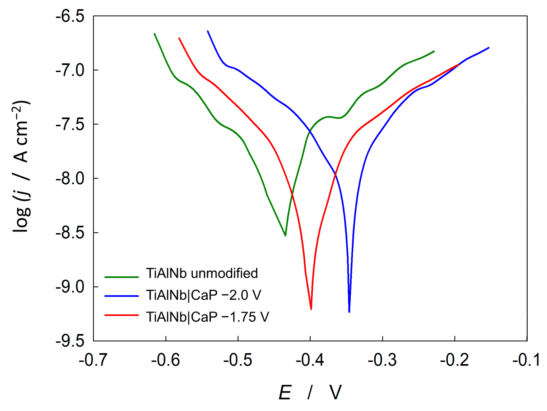
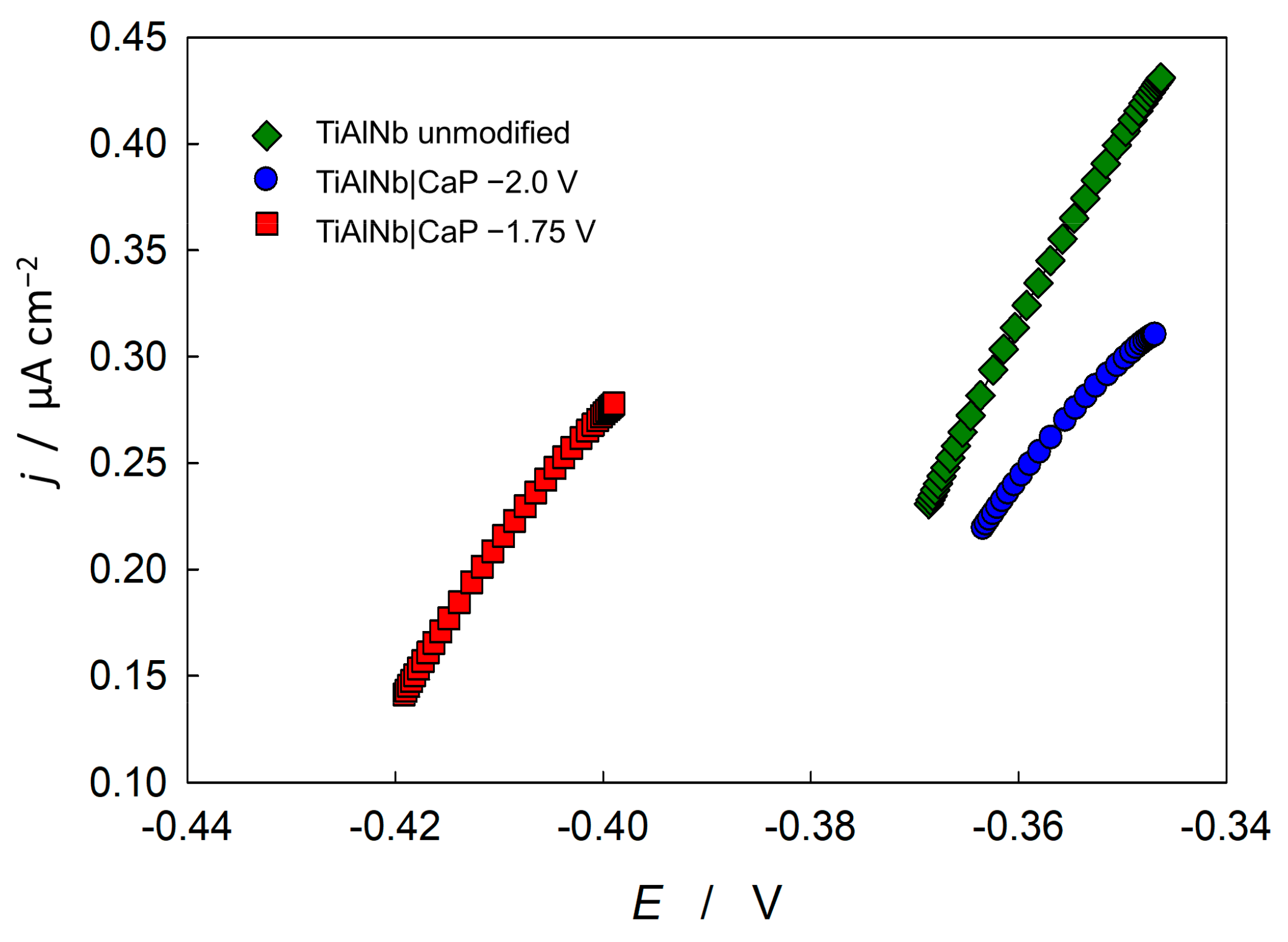
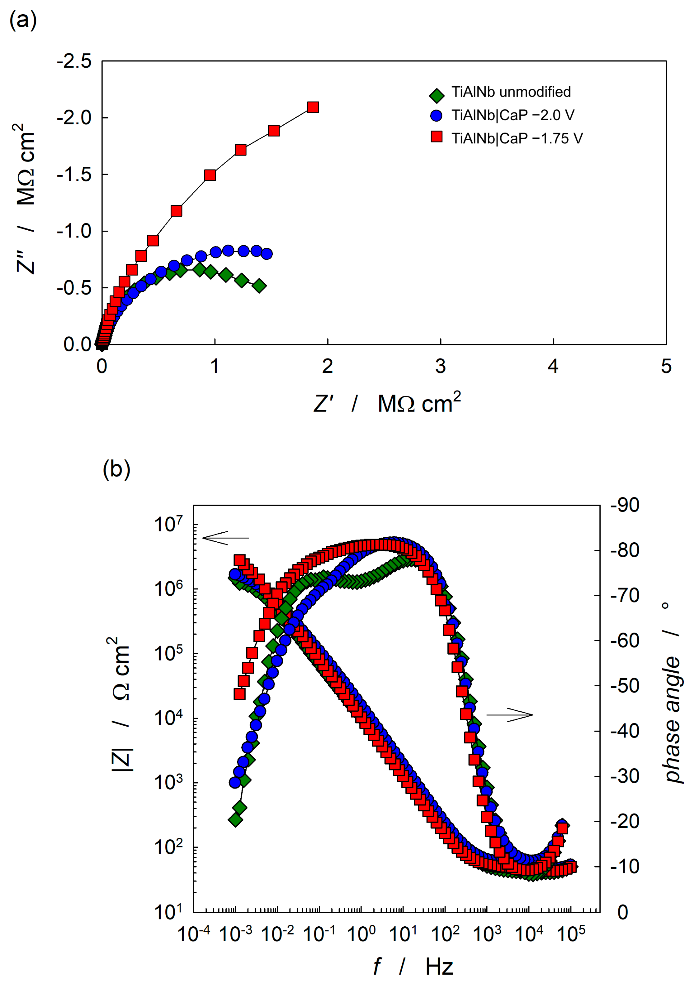
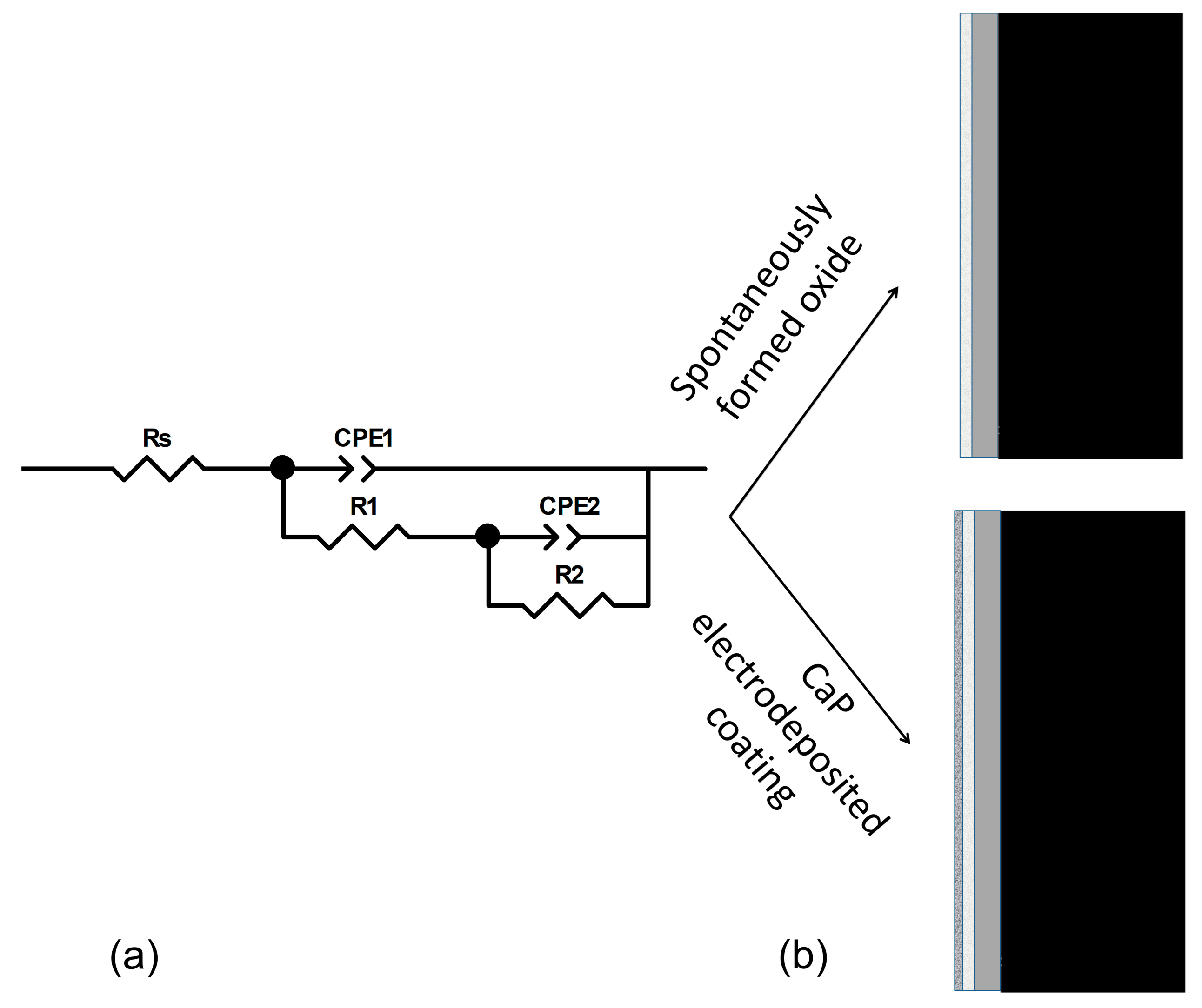
3.2. Electrochemical Characterisation of Calcium Phosphate Coatings on Titanium Alloy

Potentiodynamic polarisation testsThe electrochemical behaviour and corrosion parameters of calcium phosphate coatings electrodeposited on titanium alloy were probed by potentiodynamic polarisation tests in a wide potential range (±200 mV vs. open circuit potential, Eoc). The measurements were conducted in a simulated physiological solution, Hanks’ solution after a stabilisation time of one hour. The representative polarisation curves obtained for the unmodified and modified titanium alloy are shown in Figure 3.
The kinetic parameters of the electrochemical corrosion reaction: the corrosion potential, Ecorr, the corrosion current density, jcorr, the anodic and cathodic Tafel slopes, ba and bc and the polarisation resistance, Rp were determined by the Tafel extrapolation method and by using the Stern–Geary equation [58]. The repeatability of the results was determined by performing the polarisation measurements at least three times for each system tested. The obtained mean values of the corrosion parameters and the standard deviations are listed in Table 1. Statistical analyses were performed by analysis of variance (ANOVA) with a statistically significant level set at p < 0.05. The obtained p values obtained for both modified alloys compared to the unmodified alloy are less than 0.05 indicating that there is a significant difference between the mean corrosion parameters of the unmodified and the modified material.
Figure 3 shows the polarisation curves of the unmodified and CaP-modified titanium alloy recorded in Hanks’ solution. The electrochemical response of the unmodified alloy shows the typical behaviour of passive metals/alloys, with low current density value (j ≈ 10−8 A cm−2) characteristic of materials with a protective, passive surface film. Moreover, the anode branch of the polarisation curve remains in the potential range from −0.40 to −0.36 V at about 10−7.4 A cm−2, indicating the formation of a passive film. Above the stated potential values, the current response shows a linear function of the potential, pointing to a breakdown of the barrier film during polarisation.
Both modified substrates show equal or nobler values of corrosion potentials, followed by even lower values of corrosion current densities, jcorr suggesting a lesser tendency to corrode in the tested simulated biological medium. In addition, the modified substrates exhibit higher polarisation resistance, Rp as shown by the values given in Table 1. These observations point out the beneficial effect of the CaP coating on the corrosion resistance of the titanium alloy and reveal the formation of an effective barrier coating, as will be additionally discussed later.
Potentiodynamic polarisation tests were also performed in Hanks’ solution in a narrow potential range (±20 mV vs. open circuit potential, Eoc), linear polarisation resistance (LPR) measurements. The representative LPR curves obtained for the unmodified and modified titanium alloy are shown in Figure 4. The mean values of the corrosion parameters and standard deviations are given in Table 2.
The results obtained with the LPR method are in agreement with the results from the Tafel extrapolation method. Compared to the unmodified TiAlNb alloy, the corrosion current densities, jcorr are lower, while the polarisation resistances, Rp are higher for the modified substrates. The titanium alloy modified by the CaP coating electrodeposited at −1.75 V shows the highest polarisation resistance values and the lowest corrosion current densities, while the unmodified alloy shows the lowest polarisation resistance values. The positive contribution of the CaP deposit to the corrosion properties of the TiAlNb alloy in Hanks’ solution was additionally confirmed by the LPR–technique.
Electrochemical impedance spectroscopy—The barrier properties and corrosion behaviour of unmodified and modified TiAlNb substrates were tested using electrochemical impedance spectroscopy (EIS). The impedance spectra recorded in Hanks’ solution at the open circuit potential, Eoc after 1 h of stabilisation are presented in form of Bode and Nyquist plots (Figure 5).
The Nyquist plots show incomplete semicircles for all investigated systems, which is a characteristic behaviour of coated alloys and indicates a near capacitive response. The shape of the Bode spectra for all systems investigated shows the slope of log |Z| vs. log f in the mid-frequency region close to −1, which also indicates a semi-capacitive behaviour. Both real and imaginary impedance parameters (Z’ and –Z’’) show the lowest values for the unmodified TiAlNb substrate and the highest values for the substrate with CaP coating electrodeposited at −1.75 V. The CaP coating has a beneficial effect on the corrosion properties of the titanium alloy, as can be seen from the wider, unfinished, depressed semi-circular responses in the Nyquist spectra and the higher low-frequency impedance magnitude values in the Bode spectra.
The impedance data were modelled using the complex non-linear least squares (CNLS) fit analysis [57] and the impedance parameter values obtained are listed in Table 3. The data were fitted to the electrical equivalent circuit, EEC with two time constants (see Figure 6a), using a constant-phase element, CPE instead of a capacitor to compensate for non-homogeneity in the system (microscopic inhomogeneity, surface roughness) [59,60,61]. The CPE impedance is defined as ZCPE = 1/[Q(jω)n], where Q is the frequency-independent constant, n is the CPE exponent representing the degree of non-ideal capacitor behaviour, and ω is the angular frequency [59,60]. The values of the interfacial capacitance, C were calculated using Brug’s equation [62], where Rs is the solution resistance, and are listed in Table 3:
C = Q1/n [Rs−1 + R−1](n−1)/n
For unmodified titanium alloy, the impedance values of the alloy | solution interface are governed by the surface oxide film that spontaneously forms on the alloy, i.e., the elements in EEC correspond to the structure of bi-layered oxide film [23,63,64,65,66]. The high/medium frequency time constant (R1–CPE1) describes the properties of the outer part of the oxide film, while the low-frequency time constant (R2–CPE2) describes the properties of the inner part of the barrier oxide film (schematically shown in Figure 6b). The surface film of the unmodified TiAlNb alloy in Hanks’ solution is predominantly TiO2, with traces of aluminium oxide, Al2O3, and niobium oxides, Nb2O5, NbO, and/or NbO2 incorporated in the oxide film, as shown by previous X-ray photoelectron spectroscopy (XPS) studies [23,67]. The inner barrier part of the oxide film represents the major contribution to the overall corrosion resistance of the TiAlNb alloy, as confirmed by higher R2 resistance contribution values and lower C2 capacitance values compared to the corresponding values of the outer part of the oxide film (R1 and C1 in Table 3).
In the case of the calcium phosphate electrodeposited film, the high/medium frequency time constant (R1–CPE1) is associated with the outer and the low-frequency time constant (R2–CPE2) with the inner part of the surface film (calcium phosphate coating electrodeposited over the spontaneously formed TiO2 oxide film, CaP deposit interconnected with the TiO2 film). The EEC and titanium alloy | surface film interface are schematically presented in Figure 6a,b, respectively. The used EEC has previously been published for surface film-covered titanium and its alloys [46,68,69,70,71].
The electrodeposition of the CaP coating on TiAlNb has a major effect on the impedance response of the titanium alloy, as can be seen from the higher impedance magnitude values, |Z| associated with the higher –θ values in the broad frequency range. Higher |Z| values (>106 Ω cm2) at the lowest frequencies indicate insulating (dielectric) and protective properties of the CaP deposit bonded to the TiO2 film, compared to the unmodified titanium alloy covered with a spontaneously formed oxide film. The phase angle values, as a structurally responsive feature, also show the changes in the shape of the impedance spectra due to the CaP electrodeposition process. The coated substrates showed the –θ maximum that extended over a wider frequency range.
Based on the impedance parameter values, the resistance component values R1 and R2 significantly increased by the CaP coating formation, especially the R1 values (Table 3). For the CaP-coated alloy, this resistance component represents the resistance of the porous part of the surface film and is related to the entry of the electrolyte into the pores. Thus, the higher R1 values compared to the unmodified alloy point to filling up the compositional imperfections during CaP electrodeposition.
For the CaP coating electrodeposited at −1.75 V, the increment in resistance values was more prominent compared to the coating electrodeposited at −2.0 V. The improved corrosion behaviour of the CaP-modified sample formed at higher potential is also evident from a wider semicircle in the Nyquist plot and higher low-frequency impedance values, |Z| in the Bode plot, Figure 5. Electrodeposition at lower potential promotes the hydrogen evolution reaction on the electrode surface, reducing the degree of deposit surface coverage. This was corroborated by more than seven times lower R1 values for the coating electrodeposited at −2.0 V compared to the coating electrodeposited at −1.75 V. For the CaP coating formed at a lower potential, the –θ values show two distinct maxima and a narrower maximum frequency range in contrast to the CaP coating formed at a higher potential, which shows higher –θ values in a wider frequency range, indicating better corrosion protection.
The polarisation (corrosion) resistance, Rp, equal to the sum of R1 and R2 resistance contributions, determines the overall corrosion resistance of the oxide-covered, including CaP-coated, titanium alloy [72]. According to the Rp values (Table 3), the CaP coating formed at higher potential provides better corrosion (barrier) properties to the TiAlNb alloy in Hanks’ solution. The Rp values obtained from the impedance results by the CNLS fit analysis agree well with the corresponding values obtained by the Tafel extrapolation method and the LPR method (Table 1 and Table 2).
The electrodeposited coating influences the structural defects and imperfections that occur in the spontaneously formed oxide layer (higher R1 and R2 values compared to the unmodified alloy). However, the CaP coating formed at a lower potential (−2.0 V) exhibits a much more porous inhomogeneous structure of the inner part of the surface film, which is reflected in lower n2 values. This may be due to the competing process of hydrogen evolution reaction accompanied by hydrogen bubbles observed during electrodeposition at a lower potential, which interferes with the CaP coating deposition and affects the homogenous uniform surface film formation. On the other hand, the CaP coating electrodeposited at a higher potential (−1.75 V) resulted in higher n2 values and lower C2 values, confirming the formation of a thicker surface film with higher surface degree coverage and more barrier (protective) properties.

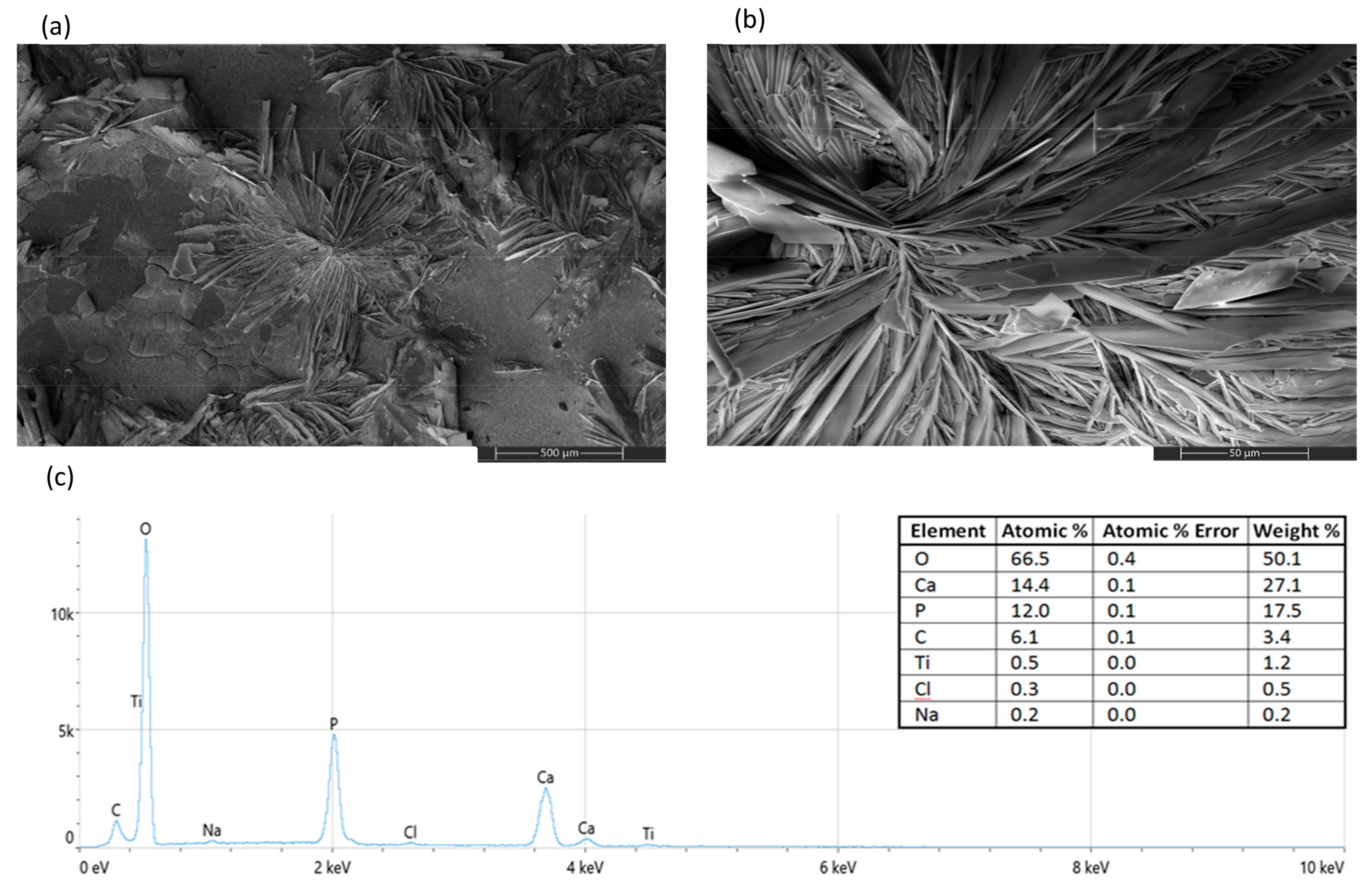
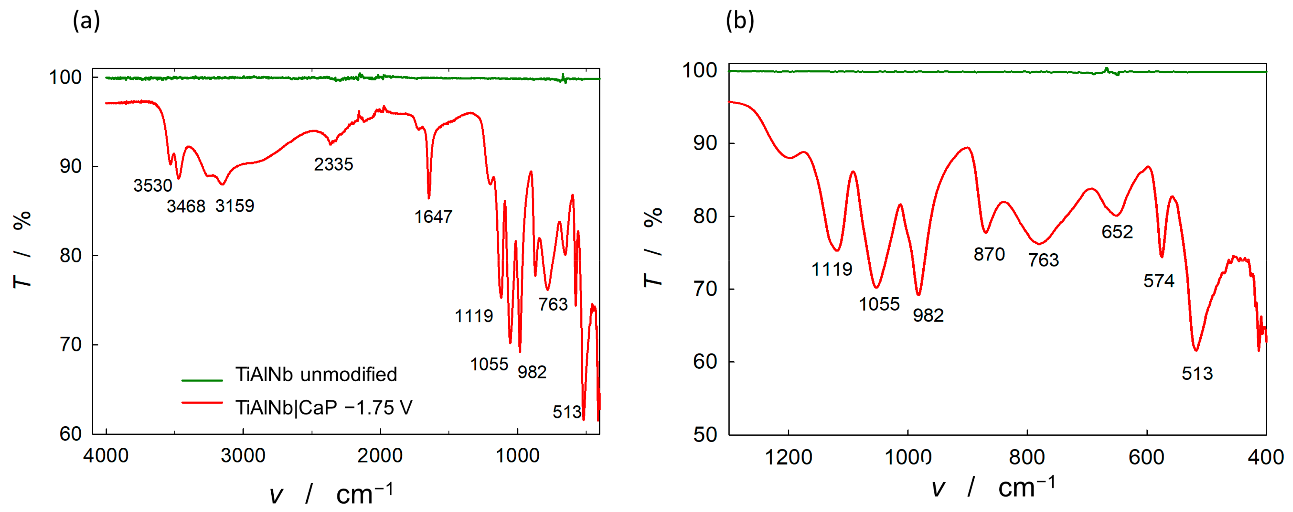
3.3. Structural and Morphological Characterisation of Calcium Phosphate Coatings on Titanium Alloy

Scanning electron microscopy (SEM)/Energy dispersive X-ray spectroscopy (EDS)—The microstructure and morphological properties as well as the composition of the coating electrodeposited at −1.75 V were investigated using SEM/EDS. The distinct structure at different magnifications, given in Figure 7a,b, shows a flower-like laminated structure on flat-surfaced island deposits. The observed flower-like laminated structures are micrometre-sized clusters with nanometre-sized cross-sections of a single flower petal. Similar morphologies were obtained previously [28,47,51,73]. The different morphologies are present due to the stages of nucleation and growth during the CaP electrodeposition process.
During electrodeposition, a stage of instantaneous nucleation and two-dimensional growth is followed by a stage of progressive nucleation and three-dimensional growth [74]. The nucleus phases developed in the initial stages spread out during hemispherical diffusion, leading to enlaced nuclei growth during planar diffusion [75], resulting in a laminated deposit structure. The observed dendritic, flower-like arrangement of clusters indicated preferential formation of CaP deposits due to a local pH increase and saturation of Ca2+, PO43–, and OH ion concentrations at specific sites of the substrate alloy [47,51]. In addition, hydrogen gas evolution as a competing process influenced the electrodeposition process by hindering the deposit growth. This resulted in the preferential deposition of the coating with a certain degree of porosity and non-compactness (Figure 7a).
Surface morphology and topography play an important role in the processes of bone cell attachment, growth, proliferation, and new bone formation [30,31,38,55]. For better implantation, the existence of surface irregularities and porosity promotes cell adhesion and proliferation due to a larger surface area [52]. It has already been shown that the electrodeposited CaP coating with the morphology of flower-like agglomerates possesses good MG-63 osteoblast-like cell viability and good results in live/dead cell staining [76]. The EDS data, given in Figure 7c, reveal the calcium phosphate constituents (Ca, P, and O) and trace element Ti from the substrate alloy, confirming the successful formation of the CaP coating on TiAlNb. The elemental composition is given in the inset table. The low Ti content signals observed and the absence of Al and Nb signals demonstrate the efficient surface coverage upon the electrodeposition coating process. Based on the elemental analysis, the Ca/P is equal to 1.2, indicating the probable presence of an amorphous calcium phosphate phase [28,30,34,37]. Considering the kinetic aspect and Ostwald’s rule that the first nucleated phase during phase transformation via crystallisation is not necessarily the most thermodynamically stable, but a phase exhibiting a free energy mostly resembling original, calcium phosphate phases with a lower Ca/P ratio are considered as apatite precursors for the hydroxyapatite formation [77]. The high solubility of the formed amorphous calcium phosphate phase allows rapid in vivo transformation to the apatite phase upon contact with human body fluids, which promotes implant osseointegration and accelerates the kinetics of initial bone formation [29,30,31]. The osteoconductive mechanism during implantation involves re-precipitation of released Ca2+ and PO43– ions during the partial dissolution of the electrodeposited CaP coating and incorporation of the ions into the apatite phase with the collagen matrix as the organic bone component [29,31,35]. In addition, based on EDS data, the determined significant carbon content points to the formation of the low crystallinity carbonate calcium phosphates, i.e., carbonate apatite. The presence of carbonate in the electrodeposited coating is not necessarily detrimental, as the biological calcium phosphates, as the main constituents of bones, also consist of carbonate phases [30,32,37]. Thus, due to its natural bone resemblance, this content provides a facilitated biological response and influences the processes of biomineralisation and new bone growth process [29,30,31,32].
Attenuated total reflectance Fourier transform infrared spectroscopy (ATR-FTIR)—Surface characterisation (composition) of electrodeposited films on the TiAlNb alloy substrates was performed using ATR-FTIR. The spectra of the unmodified and modified TiAlNb alloy samples are shown in Figure 8.
Comparing the ATR-FTIR transmission spectra of the unmodified and modified TiAlNb alloy, the spectrum of the modified alloy shows prominent bands characteristic for phosphate/apatite films (the characteristic P–O and P=O bands in the fingerprint region shown in Figure 8b). The observed intense dominant bands are typical of phosphate films: the asymmetric bending vibrations, ν4 PO43– bands at 510–600 cm−1 (fundamental O–P–O vibrations), the ν1 PO43– band at 962 cm−1 (P–O symmetric stretching vibrations) and pronounced ν3 PO43– absorption bands in the range 1150–1000 cm−1 (P–O antisymmetric stretching vibrations) [78,79,80,81,82]. The bands at about 3530, 3470, 3160, and 650 cm−1 are the result of the stretching of hydroxyl groups, including the vibration band, in the apatite/hydroxyapatite form [80,81]. Moreover, the band at 1647 cm−1 is assigned to the ν2 bending mode of adsorbed water associated with the hydroxyapatite phase [78].
Strong FTIR spectra bands observed at 870 cm−1 and 763 cm−1 can be attributed to the ν2 symmetric and ν4 symmetric stretching vibrations of carbonate ions, respectively [78,79,83]. These bands are accompanied by a weak peak at 2335 cm−1 resulting from the asymmetric stretching mode of gaseous carbon dioxide present due to the atmospheric conditions during the electrodeposition process, indicating adsorbed carbonate ions [30,80]. It is known that the carbonate ions can replace hydroxyl or phosphate ions in the apatite coatings leading to the formation of calcium-deficient hydroxyapatite and affecting the Ca/P ratio [30], which is consistent with EDS data shown. Regardless, the carbonate apatite content in the electrodeposited CaP enables a better mimicking of the natural bone mineral composition [32,33,34,35,36]. The observed CaP electrodeposited coating content is in full compliance with the conditions/requirements specified in ASTM F1185-03R14 [84] and ISO 13779-2:2018 and 13779-3:2018 standards [85,86] for orthopaedic implant coatings application.
In summary, the bands observed at 574, 962 and 1055 cm−1 represent the characteristic bands for the phosphate group and are accompanied by the bands at 650 and 3530 cm−1, which are typical bands of the hydroxyl group in the hydroxyapatite/apatite coating [30]. In addition, the electrodeposited coating consists of low-level content of carbonated hydroxyapatite/apatite. This provides similarities in bone properties that are helpful for improved bioactivity, biodegradability, and osteoconductivity [29,30,31,32]. After implantation, the electrodeposited CaP coating with its carbonate apatite content adsorbs circulating proteins (from the biological environment) to which bone cells attach, migrate, proliferate, and differentiate, leading to matrix production, biomineralisation, and new bone formation [29,30,31,32].

4. Conclusions

The titanium alloy, TiAlNb, commonly commercially used as an implant material in orthopaedic devices, has been modified by electrochemically deposited functional bioactive calcium phosphate (CaP) coating. CaP coatings, as osteoinductive materials, promote physiological processes of cell adhesion and bone ingrowth, thus enhancing the biological performance, biocompatibility, and bioactivity of the titanium alloy as a high-strength implant material.
Electrochemical characterisation of unmodified and CaP-coated titanium alloy was performed by ac and dc electrochemical methods in simulated body fluid, Hanks’ solution. The results showed improved corrosion (barrier) properties (lower corrosion current densities, jcorr and higher polarisation resistances, Rp) for the underlying Ti alloy after the CaP electrodeposition.
According to the electrochemical impedance (EIS) conducted under real application conditions, the CaP coating electrodeposited at a lower potential (−2.0 V) provided lower anti-corrosion protection (Rp~2.25 MΩ cm2) since the competing process of hydrogen evolution hindered the growth of the CaP layer and affected the porosity and structural homogeneity of the coating (lower n2, n2~0.486). In comparison, the CaP coating electrodeposited at a higher potential (−1.75 V) yielded higher n2 (n2~0.82) and Rp (Rp~3.87 MΩ cm2) values, confirming the formation of the surface film with higher coverage and more protective properties, which is consistent with the results of the LPR and Tafel extrapolation methods.
SEM/EDS and FTIR results confirmed the successful formation of the CaP coating on the TiAlNb alloy by the electrodeposition method. The results indicate the formation of an apatite/hydroxyapatite calcium phosphate coating with a small amount of carbonated apatite/hydroxyapatite, which occurs in biological calcium phosphates as a major component of bone.
The functional electrodeposited CaP coating provides improved overall corrosion resistance and protects the TiAlNb alloy in an aggressive environment. The higher biocompatibility and bioactivity of the CaP-modified TiAlNb alloy could have a positive effect on implant stability in the human body, leading to successful implantation and a longer lifetime of the implant.

Author Contributions

Conceptualisation, J.K.; methodology, S.K., Ž.P. and J.K.; software, S.K., D.M. and M.M.; formal analysis, S.K., Ž.P., M.M. and J.K.; investigation, S.K., J.K. and Ž.P.; resources, J.K. and Ž.P.; writing—original draft preparation, J.K., S.K., D.M. and Ž.P.; writing—review and editing, J.K, S.K. and Ž.P.; supervision, J.K. All authors have read and agreed to the published version of the manuscript.

Funding

This research was partially funded by the University of Zagreb for short-term financial support for research for 2022, support topic “Functional advanced materials”.

Institutional Review Board Statement

Not applicable.

Informed Consent Statement

Not applicable.

Data Availability Statement

The data presented in this study are available on request from the corresponding author.

Acknowledgments

The authors kindly acknowledge the support from the Croatian Science Foundation project (grant IP-2019-04-5030).

Conflicts of Interest

The authors declare no conflict of interest.

References

  1. Elias, C.N.; Lima, J.H.C.; Valiev, R.; Meyers, M.A. Biomedical applications of titanium and its alloys. JOM 2008, 60, 46–49. [Google Scholar] [CrossRef]
  2. Liu, X.; Chu, P.K.; Ding, C. Surface modification of titanium, titanium alloys, and related materials for biomedical applications. Mater. Sci. Eng. R 2004, 47, 49–121. [Google Scholar] [CrossRef] [Green Version]
  3. Geetha, M.; Singh, A.K.; Asokamani, R.; Gogia, A.K. Ti based biomaterials, the ultimate choice for orthopaedic implants—A review. Prog. Mater. Sci. 2009, 54, 397–425. [Google Scholar] [CrossRef]
  4. Li, Y.; Yang, C.; Zhao, H.; Qu, S.; Li, X.; Li, Y. New Developments of Ti-Based Alloys for Biomedical Applications. Materials 2014, 7, 1709–1800. [Google Scholar] [CrossRef] [Green Version]
  5. Chen, Q.; Thouas, G.A. Metallic implant biomaterials. Mater. Sci. Eng. R 2015, 87, 1–57. [Google Scholar] [CrossRef]
  6. Zhang, L.C.; Chen, L.Y. A Review on Biomedical Titanium Alloys: Recent Progress and Prospect. Adv. Eng. Mater. 2019, 21, 1801215. [Google Scholar] [CrossRef] [Green Version]
  7. Kaur, M.; Singh, K. Review on titanium and titanium-based alloys as biomaterials for orthopaedic applications. Mater. Sci. Eng. C 2019, 102, 844–862. [Google Scholar] [CrossRef]
  8. Eliaz, N. Corrosion of Metallic Biomaterials: A Review. Materials 2019, 12, 407. [Google Scholar] [CrossRef] [Green Version]
  9. Zhang, L.C.; Chen, L.Y.; Wang, L. Surface Modification of Titanium and Titanium Alloys: Technologies, Developments, and Future Interests. Adv. Eng. Mater. 2020, 22, 1901253. [Google Scholar] [CrossRef]
  10. Valko, M.; Morris, H.; Cronin, M.T.D. Metals, Toxicity and Oxidative Stress. Curr. Med. Chem. 2005, 12, 1161–1208. [Google Scholar] [CrossRef] [Green Version]
  11. Costa, B.; Tokuhara, C.K.; Rocha, L.A.; Oliveira, R.C.; Lisboa-Filho, P.N.; Costa Pessoae, J. Vanadium ionic species from degradation of Ti-6Al-4V metallic implants: In vitro cytotoxicity and speciation evaluation. Mater. Sci. Eng. C 2019, 96, 730–739. [Google Scholar] [CrossRef]
  12. Challa, V.S.A.; Mali, S.; Misra, R.D.K. Reduced toxicity and superior cellular response of preosteoblasts to Ti-6Al-7Nb alloy and comparison with Ti-6Al-4V. J. Biomed. Mater. Res. Part A 2013, 101A, 2083–2089. [Google Scholar] [CrossRef]
  13. Bozoglan, A.; Dundar, S. Comparison of osseointegration of Ti–Al6V4 and Ti–Al6Nb7 implants: An experimental study. J. Oral Biol. Craniofac. Res. 2021, 11, 624–627. [Google Scholar] [CrossRef]
  14. Chézeau, L.; Tchinda, A.; Pierson, G.; Bravetti, P.; Ferrari, L.; Joubert, O.; Zaiou, M.; Rihn, B.H. In Vitro Molecular Study of Titanium-Niobium Alloy Biocompatibility. Biomedicines 2022, 10, 1898. [Google Scholar] [CrossRef]
  15. Narayanan, R.; Seshadri, S.K.; Kwon, T.Y.; Kim, K.H. Calcium Phosphate-Based Coatings on Titanium and Its Alloys. J. Biomed. Mater. Res. Part B Appl. Biomater. 2008, 85B, 279–299. [Google Scholar] [CrossRef]
  16. Niimoni, M. Metals for Biomedical Devices, 2nd ed.; Elsevier Woodhead Publishing: Duxford, UK, 2019; pp. 3–94. [Google Scholar]
  17. Gao, A.; Hang, R.; Bai, L.; Tang, B.; Chu, P.K. Electrochemical surface engineering of titanium-based alloys for biomedical application. Electrochim. Acta 2018, 271, 699–718. [Google Scholar] [CrossRef]
  18. Hiromoto, S. Corrosion of metallic biomaterials. In Metals for Biomedical Devices, 2nd ed.; Niinomi, M., Ed.; Elsevier Woodhead Publishing: Duxford, UK, 2019; pp. 131–152. [Google Scholar] [CrossRef]
  19. Bochetta, P.; Chen, L.Y.; Corpa Tardell, J.D.; Reis, A.C.; Alemraya-CAlderon, F.; Leo, P. Passive Layers and Corrosion Resistance of Biomedical Ti-6Al-4V and β-Ti Alloys. Coatings 2021, 11, 487. [Google Scholar] [CrossRef]
  20. Singh, R.; Dahotre, N.B. Corrosion degradation and prevention by surface modification of biometallic materials. J. Mater. Sci. Mater. Med. 2007, 18, 725–751. [Google Scholar] [CrossRef]
  21. Asri, R.I.M.; Harun, W.S.W.; Samykano, M.; Lah, N.A.C.; Ghani, S.A.C.; Tarlochan, F.; Raza, M.R. Corrosion and surface modification on biocompatible metals: A review. Mater. Sci. Eng. C 2017, 77, 1261–1274. [Google Scholar] [CrossRef] [Green Version]
  22. Manam, N.S.; Harun, W.S.W.; Shri, D.N.A.; Ghani, S.A.C.; Kurniawan, T.; Ismail, M.H.; Ibrahim, M.H.I. Study of corrosion in biocompatible metals for implants: A review. J. Alloys Compd. 2017, 701, 698–715. [Google Scholar] [CrossRef] [Green Version]
  23. Milošev, I.; Kosec, T.; Strehblow, H.H. XPS and EIS study of the passive film formed on orthopaedic Ti–6Al–7Nb alloy in Hank’s physiological solution. Electrochim. Acta 2008, 53, 3547–3558. [Google Scholar] [CrossRef]
  24. Goodman, S.B.; Yao, Z.; Keeney, M.; Yang, F. The future of biologic coatings for orthopaedic implants. Biomaterials 2013, 34, 3174–3183. [Google Scholar] [CrossRef] [PubMed] [Green Version]
  25. Spriano, S.; Yamaguchi, S.; Baino, F.; Ferraris, S. A critical review of multifunctional titanium surfaces: New frontiers for improving osseointegration and host response, avoiding bacteria contamination. Acta Biomater. 2018, 79, 1–22. [Google Scholar] [CrossRef] [PubMed]
  26. Souza, J.C.M.; Sordi, M.B.; Kanazawa, M.; Ravindran, S.; Henriques, B.; Silva, F.S.; Aparicio, C.; Cooper, L.F. Nano-scale modification of titanium implant surfaces to enhance osseointegration. Acta Biomater. 2019, 94, 112–131. [Google Scholar] [CrossRef] [PubMed]
  27. Paital, S.R.; Dahotre, N.B. Calcium phosphate coatings for bio-implant applications: Materials, performance factors, and methodologies. Mater. Sci. Eng. R 2009, 66, 1–70. [Google Scholar] [CrossRef]
  28. Dorozhkin, S.V. Calcium orthophosphate deposits: Preparation, properties and biomedical applications. Mater. Sci. Eng. C 2015, 55, 272–326. [Google Scholar] [CrossRef]
  29. Tang, Z.; Li, X.; Tan, Y.; Fan, H.; Zhang, X. The material and biological characteristics of osteoinductive calcium phosphate ceramics. Regen. Biomater. 2018, 1, 43–59. [Google Scholar] [CrossRef] [Green Version]
  30. Eliaz, N.; Metoki, N. Calcium Phosphate Bioceramics: A Review of Their History, Structure, Properties, Coating Technologies and Biomedical Applications. Materials 2017, 10, 334. [Google Scholar] [CrossRef] [Green Version]
  31. Xiao, D.; Zhang, J.; Zhang, C.; Barbieri, D.; Yuan, H.; Moroni, L.; Feng, G. The role of calcium phosphate surface structure in osteogenesis and the mechanisms involved. Acta Biomater. 2020, 106, 22–33. [Google Scholar] [CrossRef]
  32. LeGeros, R.Z. Calcium Phosphate-Based Osteoinductive Materials. Chem. Rev. 2008, 108, 4742–4753. [Google Scholar] [CrossRef]
  33. Dorozhkin, S.V. Amorphous calcium (ortho)phosphates. Acta Biomater. 2010, 6, 4457–4475. [Google Scholar] [CrossRef]
  34. Dorozhkin, S.V. Calcium Orthophosphate-Based Bioceramics. Materials 2013, 6, 3840–3942. [Google Scholar] [CrossRef] [Green Version]
  35. Surmenev, R.A.; Surmeneva, M.A.; Ivanova, A.A. Significance of calcium phosphate coatings for the enhancement of new bone osteogenesis—A review. Acta Biomater. 2014, 10, 557–579. [Google Scholar] [CrossRef]
  36. Ambard, A.J.; Mueninghoff, L. Calcium phosphate cement: Review of mechanical and biological properties. J. Prosthodont. 2006, 15, 321–328. [Google Scholar] [CrossRef]
  37. Habraken, W.; Habibovic, P.; Epple, M.; Bohner, M. Calcium phosphates in biomedical applications: Materials for the future? Mater. Today 2016, 19, 69–87. [Google Scholar] [CrossRef]
  38. Jeong, J.; Kim, J.H.; Shim, J.H.; Hwanf, N.S.; Heo, C.Y. Bioactive calcium phosphate materials and applications in bone regeneration. Biomater. Res. 2019, 23, 4. [Google Scholar] [CrossRef] [Green Version]
  39. Tsui, Y.C.; Doyle, C.; Clyne, T.W. Plasma sprayed hydroxyapatite coatings on titanium substrates, Part 1: Mechanical properties and residual stress levels. Biomaterials 1998, 19, 2015–2029. [Google Scholar] [CrossRef]
  40. Peng, F.; Shaw, M.T.; Olson, J.R.; Wei, M. Influence of surface treatment and biomimetic hydroxyapatite coating on the mechanical properties of hydroxyapatite/poly(L-lactic acid) fibers. J. Biomater. Appl. 2012, 27, 641–649. [Google Scholar] [CrossRef]
  41. Lopez-Heredia, M.A.; Weiss, P.; Layrolle, P. An electrodeposition method of calcium phosphate coatings on titanium alloy. J. Mater. Sci. Mater. Med. 2007, 18, 381–390. [Google Scholar] [CrossRef]
  42. Katić, J.; Metikoš-Huković, M.; Babić, R.; Marciuš, M. Sol-gel Derived Biphasic Calcium Phosphate Ceramics on Nitinol for Medical Applications. Int. J. Electrochem. Sci. 2013, 8, 1394–1408. [Google Scholar]
  43. Katić, J.; Metikoš-Huković, M.; Babić, R. Synthesis and characterization of calcium phosphate coatings on Nitinol. J. Appl. Electrochem. 2014, 44, 87–96. [Google Scholar] [CrossRef]
  44. Kreller, T.; Sahm, F.; Bader, R.; Boccaccini, A.R.; Jonitz-Heincke, A.; Detsch, R. Biomimetic Calcium Phosphate Coatings for Bioactivation of Titanium Implant Surfaces: Methodological Approach and In Vitro Evaluation of Biocompatibility. Materials 2021, 14, 3516. [Google Scholar] [CrossRef] [PubMed]
  45. Katić, J.; Metikoš-Huković, M.; Škapin, S.D.; Petravić, M.; Varašanec, M. The potential-assisted deposition as valuable tool for producing functional apatite coatings on metallic materials. Electrochim. Acta 2014, 127, 173–179. [Google Scholar] [CrossRef]
  46. Gad El-Rab, S.M.F.; Fadl-allah, S.A.; Montser, A.A. Improvement in antibacterial properties of Ti by electrodeposition of biomimetic Ca–P apatite coat on anodized titania. Appl. Surf. Sci. 2012, 261, 1–7. [Google Scholar] [CrossRef]
  47. He, D.-H.; Wang, P.; Liu, P.; Liu, X.-K.; Ma, F.-C.; Zhao, J. HA coating fabricated by electrochemical deposition on modified Ti6Al4V alloy. Surf. Coat. Technol. 2016, 301, 6–12. [Google Scholar] [CrossRef]
  48. Bucur, A.I.; Linul, E.; Taranu, B.O. Hydroxyapatite coatings on Ti substrates by simultaneous precipitation and electrodeposition. Appl. Surf. Sci. 2020, 527, 146820. [Google Scholar] [CrossRef]
  49. Bruchiel-Spanier, N.; Betsis, S.; Naium, G.; Mandler, D. Electrochemical and electrophoretic coatings of medical implants by nanomaterials. J. Solid State Elctrochem. 2022, 26, 1871–1896. [Google Scholar] [CrossRef]
  50. Li, T.T.; Ling, L.; Lin, M.C.; Peng, H.K.; Ren, H.T.; Lou, C.W.; Lin, J.H. Recent advances in multifunctional hydroxyapatite coating by electrochemical deposition. J. Mater. Sci. 2020, 55, 6352–6374. [Google Scholar] [CrossRef]
  51. Drevet, R.; Benhayoune, H. Electrodeposition of Calcium Phosphate Coatings on Metallic Substrates for Bone Implant Applications: A Review. Coatings 2022, 12, 539. [Google Scholar] [CrossRef]
  52. Beig, B.; Liaqat, U.; Niazi, M.F.K.; Douna, I.; Zahoor, M.; Niazi, M.B.K. Current Challenges and Innovative Developments in Hydroxyapatite-Based Coatings on Metallic Materials for Bone Implantation: A Review. Coatings 2020, 10, 1249. [Google Scholar] [CrossRef]
  53. Jiang, P.; Zhang, Y.; Hu, R.; Wang, X.; Lai, Y.; Rui, G.; Lin, C. Hydroxyapatite-modified micro/nanostructured titania surfaces with different crystalline phases for osteoblast regulation. Bioact. Mater. 2021, 6, 1118–1129. [Google Scholar] [CrossRef]
  54. Lin, K.; Wu, C.; Chang, J. Advances in synthesis of calcium phosphate crystals with controlled size and shape. Acta Biomater. 2014, 10, 4071–4102. [Google Scholar] [CrossRef]
  55. Hou, X.; Zhang, L.; Zhou, Z.; Luo, X.; Wang, T.; Zhao, X.; Lu, B.; Chen, F.; Zheng, L. Calcium Phosphate-Based Biomaterials for Bone Repair. J. Funct. Biomater. 2022, 13, 187. [Google Scholar] [CrossRef]
  56. ISO 5832-11:2014; Implants for Surgery—Metallic Materials—Part 11: Wrought Titanium 6-Aluminium 7-Niobium Alloy. British Standards Institution: London, UK, 2014.
  57. Boukamp, A. A Nonlinear Least Squares Fit procedure for analysis of immittance data of electrochemical systems. Solid State Ionics 1986, 20, 31–44. [Google Scholar] [CrossRef] [Green Version]
  58. Popov, B.N. Electrochemical Kinetics of Corrosion. In Corrosion Engineering, Principles and Solved Problems; Popov, B.N., Ed.; Elsevier B.V.: Amsterdam, The Netherlands, 2015; pp. 181–207. [Google Scholar]
  59. Jorcin, J.B.; Orazem, M.E.; Pébère, N.; Tribollet, B. CPE analysis by local electrochemical impedance spectroscopy. Electrochim. Acta 2006, 51, 1473–1479. [Google Scholar] [CrossRef]
  60. Orazem, M.E.; Tribollet, B. Electrochemical Impedance Spectroscopy; John Wiley & Sons: New York, NY, USA, 2008; pp. 233–265. [Google Scholar]
  61. Cordoba-Torres, P.; Mesquita, T.J.; Nogueira, R.P. Relationship between the Origin of Constant-Phase Element Behavior in Electrochemical Impedance Spectroscopy and Electrode Surface Structure. J. Phys. Chem. C 2015, 119, 4136–4147. [Google Scholar] [CrossRef]
  62. Brug, G.J.; van den Eeden, A.L.G.; Sluyters-Rehbach, M.; Sluyters, J.H. The analysis of electrode impedances complicated by the presence of a constant phase element. J. Electroanal. Chem. Interfacial Electrochem. 1984, 176, 275–295. [Google Scholar] [CrossRef]
  63. De Assis, S.L.; Wolynec, S.; Costa, I. Corrosion characterization of titanium alloys by electrochemical techniques. Electrochim. Acta 2006, 51, 1815–1819. [Google Scholar] [CrossRef]
  64. Katić, J.; Šarić, A.; Despotović, I.; Matijaković, N.; Petković, M.; Petrović, Ž. Bioactive Coating on Titanium Dental Implants for Improved Anticorrosion Protection: A Combined Experimental and Theoretical Study. Coatings 2019, 9, 612. [Google Scholar] [CrossRef] [Green Version]
  65. Kosec, T.; Legat, A.; Kovač, J.; Klobčar, D. Influence of Laser Colour Marking on the Corrosion Properties of Low Alloyed Ti. Coatings 2019, 9, 375. [Google Scholar] [CrossRef] [Green Version]
  66. Petrović, Ž.; Šarić, A.; Despotović, I.; Katić, J.; Peter, R.; Petravić, M.; Petković, M. A New Insight into Coating’s Formation Mechanism Between TiO2 and Alendronate on Titanium Dental Implant. Materials 2020, 13, 3220. [Google Scholar] [CrossRef] [PubMed]
  67. Sittig, C.; Textor, M.; Spencer, N.D.; Wieland, M.; Vallotton, P.H. Surface characterization of implant materials c.p. Ti, Ti-6Al-7Nb and Ti-6Al-4V with different pretreatments. J. Mater. Sci. Mater. Med. 1999, 10, 35–46. [Google Scholar] [CrossRef] [PubMed] [Green Version]
  68. Lavos-Valereto, I.C.; Wolynec, S.; Ramires, I.; Guastaldi, A.C.; Costa, I. Electrochemical impedance spectroscopy characterization of passive film formed on implant Ti-6Al-7Nb in Hank’s solution. J. Mater. Sci. Mater. Med. 2004, 15, 55–59. [Google Scholar] [CrossRef] [PubMed]
  69. Roland, T.; Pelletier, H.; Krier, J. Scratch resistance and electrochemical corrosion behavior of hydroxyapatite coatings on Ti6Al4V in simulated physiological media. J. Appl. Electrochem. 2013, 43, 53–56. [Google Scholar] [CrossRef]
  70. Mashtalyar, D.V.; Nadaraia, K.V.; Gnedenkov, A.S.; Imshinetskiy, I.M.; Piatkova, M.A.; Pleshkova, A.I.; Belov, E.A.; Filonina, V.S.; Suchkov, S.N.; Sinebryukhov, S.L.; et al. Bioactive Coatings Formed on Titanium by Plasma Electrolytic Oxidation: Composition and Properties. Materials 2020, 13, 4121. [Google Scholar] [CrossRef]
  71. Petrović, Ž.; Šarić, A.; Despotović, I.; Katić, J.; Peter, R.; Petravić, M.; Ivanda, M.; Petković, M. Surface Functionalisation of Dental Implants with a Composite Coating of Alendronate and Hydrolysed Collagen: DFT and EIS Studies. Materials 2022, 15, 5127. [Google Scholar] [CrossRef]
  72. Scully, J.R. Polarization Resistance Method for Determination of Instantaneous Corrosion Rates. Corrosion 2000, 56, 199–218. [Google Scholar] [CrossRef]
  73. Dumelié, N.; Benhayoune, H.; Rousse-Bertrand, C.; Bouthors, S.; Perchet, A.; Wortham, L.; Douglade, J.; Laurent-Maquin, D.; Balossier, G. Characterization of electrodeposited calcium phosphate coatings by complementary scanning electron microscopy and scanning-transmission electron microscopy associated to X-ray microanalysis. Thin Solid Films 2005, 492, 131–139. [Google Scholar] [CrossRef]
  74. Eliaz, N.; Eliyahu, M. Electrochemical processes of nucleation and growth of hydroxyapatite on titanium supported by real-time electrochemical atomic force microscopy. J. Biomed. Mater. Res. A 2007, 80, 621–634. [Google Scholar] [CrossRef]
  75. Koumya, Y.; Salam, Y.A.; Khadiri, M.E.; Benzakour, J.; Romane, A.; Abouelfida, A.; Benyaich, A. Pitting corrosion behavior of SS-316L in simulated body fluid and electrochemically assisted deposition of hydroxyapatite coating. Chem. Papers 2021, 75, 2667–2682. [Google Scholar] [CrossRef]
  76. Furko, M.; Della Bella, E.; Fini, M.; Balazsi, C. Corrosion and biocompatibility examination of multi-element modified calcium phosphate bioceramic layers. Mater. Sci. Eng. C 2019, 95, 381–388. [Google Scholar] [CrossRef]
  77. Eliaz, N.; Kopelovitch, W.; Burstein, L.; Kobayashi, E.; Hanawa, T. Electrochemical processes of nucleation and growth of calcium phosphate on titanium supported by real-time quartz crystal microbalance measurements and X-ray photoelectron spectroscopy analysis. J. Biomed. Mater. Res. A 2009, 89A, 270–280. [Google Scholar] [CrossRef]
  78. Koutsopoulos, S. Synthesis and characterization of hydroxyapatite crystals: A review study on the analytical methods. J. Biomed. Mater. Res. 2002, 62, 600–612. [Google Scholar] [CrossRef]
  79. Chukanov, N.V.; Chervonnyi, A.D. IR Spectra of Minerals and Related Compounds, and Reference Samples’ Data. In Infrared Spectroscopy of Minerals and Related Compounds; Chukanov, N.V., Chervonnyi, A.D., Eds.; Springer Cham: Heidelberg, Germany, 2015; pp. 51–1047. [Google Scholar] [CrossRef]
  80. Berzina-Cimdina, L.; Borodajenko, N. Research of Calcium Phosphates Using Fourier Transform Infrared Spectroscopy. In Infrared Spectroscopy—Materials Science, Engineering and Technology; Theophanides, T., Ed.; IntechOpen: Rijeka, Croatia, 2012; pp. 123–148. [Google Scholar] [CrossRef] [Green Version]
  81. Buljan Meić, I.; Kontrec, J.; Domazet Jurašin, D. Comparative Study of Calcium Carbonates and Calcium Phosphates Precipitation in Model Systems Mimicking the Inorganic Environment for Biomineralization. Cryst. Growth Des. 2017, 17, 1103–1117. [Google Scholar] [CrossRef]
  82. Popa, M.V.; Moreno, J.M.C.; Popa, M.; Vasilescu, E.; Drob, P.; Vasilescu, C.; Drob, S.I. Electrochemical deposition of bioactive coatings on Ti and Ti–6Al–4V surfaces. Surf. Coat. Technol. 2011, 205, 4776–4783. [Google Scholar] [CrossRef]
  83. Xu, B.; Poduska, K.M. Linking crystal structure with temperature-sensitive vibrational modes in calcium carbonate minerals. Phys. Chem. Chem. Phys. 2014, 16, 17634–17639. [Google Scholar] [CrossRef] [Green Version]
  84. ASTM F1185-03(2014); Standard Specification for Composition of Hydroxylapatite for Surgical Implants. ASTM International: West Conshohocken, PA, USA, 2014. [CrossRef]
  85. ISO 13779-2:2018; Implants for Surgery—Hydroxyapatite—Part 2: Thermally Sprayed Coatings of Hydroxyapatite. British Standards Institution: London, UK, 2018.
  86. ISO 13779-3:2018; Implants for Surgery—Hydroxyapatite—Part 3: Chemical Analysis and Characterization of Crystallinity Ratio and Phase Purity. British Standards Institution: London, UK, 2018.
Figure 1. Schematic illustration of the CaP coating preparation and electrochemical and structural characterisation methods.
Coatings 13 00640 g001
Figure 2. The cyclic voltammogram of the TiAlNb electrode recorded in the deposition electrolyte at scan rate, v = 10 mV s−1. The arrows indicate the potential scan direction.
Coatings 13 00640 g002
Figure 3. The potentiodynamic polarisation curves of the unmodified and the CaP-modified TiAlNb alloy obtained in Hanks’ solution in a potential range ±200 mV vs. open circuit potential, Eoc at the sweep rate, v = 0.1667 mV s−1.
Coatings 13 00640 g003
Figure 4. The LPR curves of the unmodified and the CaP-coated TiAlNb alloy obtained in Hanks’ solution in a potential range ±20 mV vs. open circuit potential, Eoc at the sweep rate, v = 1 mV s−1.
Coatings 13 00640 g004
Figure 5. The Nyquist (a) and Bode (b) plots of the unmodified and the CaP-coated TiAlNb alloy recorded in Hank’s solution at Eoc. Symbols: the experimental data; solid lines: the modelled data.
Coatings 13 00640 g005
Figure 6. The electric equivalent circuit (EEC) used to model the impedance spectra of the unmodified and the CaP-coated TiAlNb alloy (a) and the schematic diagram for titanium alloy | surface film interface (b).
Coatings 13 00640 g006
Figure 7. The SEM images of the CaP coating electrodeposited at −1.75 V on the TiAlNb substrate, magnification at: 50× (a) and 500× (b). The EDS analysis (c) of the presented coating section.
Coatings 13 00640 g007
Figure 8. The ATR-FTIR spectra of unmodified and modified TiAlNb alloy: (a) wide range spectra and (b) P–O bands in the fingerprint region of the spectra.
Coatings 13 00640 g008
Table 1. The mean values of the corrosion parameters with standard deviations obtained by the Tafel extrapolation method for the unmodified and the CaP-coated TiAlNb substrates.
Sampleba/mV dec−1bc/mV dec−1jcorr/nA cm−2Ecorr/VRp/MΩ cm2
TiAlNb
unmodified
112.8 ± 27.5133.4 ±23.614.7 ± 2.6−0.396 ± 0.0431.83 ± 0.43
TiAlNb|CaP
−2.0V
103.8 ± 6.2142.0 ± 12.112.4 ± 1.7−0.350 ± 0.0262.13 ± 0.31
TiAlNb|CaP
−1.75V
118.6 ± 7.5105.8 ± 19.66.4 ± 2.4−0.404 ± 0.0253.59 ± 2.03
Table 2. The mean values of the corrosion parameters (with standard deviations) obtained by the LPR method for the unmodified and the CaP-coated TiAlNb alloy.
Samplejcorr/nA cm−2Ecorr/VRp/MΩ cm2
TiAlNb
unmodified
26.0 ± 4.4−0.392 ± 0.0041.03 ± 0.19
TiAlNb|CaP
−2.0V
13.7 ± 3.2−0.391 ± 0.0321.65 ± 0.64
TiAlNb|CaP
−1.75V
9.7± 2.1−0.412 ± 0.0152.95 ± 0.69
Table 3. The mean values of the impedance parameters and the standard deviations of the unmodified and the CaP-coated TiAlNb alloy recorded in Hanks’ solution at Eoc.
SampleRS/
Ω cm2
106 × Q1/
−1 cm−2 sn1
n1R1/
kΩ cm2
C1/
μF cm−2
106 × Q2/
−1 cm−2 sn2
n2R2/
MΩ cm2
C2/
μF cm−2
Rp/
MΩ cm2
TiAlNb
unmodified
43.3 ± 0.717.14 ± 1.190.903 ± 0.01058.6 ± 16.07.85 ± 0.828.15 ± 3.710.803 ± 0.0321.39 ± 0.391.20 ± 0.421.45 ± 0.39
TiAlNb|CaP
−2.0 V
51.0 ± 5.414.54 ± 3.790.907 ± 0.020131.6 ± 24.76.96 ± 1.983.28 ± 0.540.486 ± 0.0752.12 ± 0.59/2.25 ± 0.58
TiAlNb|CaP
−1.75 V
46.9 ± 5.218.24 ± 2.860.901 ± 0.019982.2 ± 78.88.39 ± 1.995.33 ± 1.730.810 ± 0.0272.89 ± 0.530.88 ± 0.153.87 ± 0.73
Disclaimer/Publisher’s Note: The statements, opinions and data contained in all publications are solely those of the individual author(s) and contributor(s) and not of MDPI and/or the editor(s). MDPI and/or the editor(s) disclaim responsibility for any injury to people or property resulting from any ideas, methods, instructions or products referred to in the content.

