Article

Direct Energy Depositions of a 17-4 PH Stainless Steel: Geometrical and Microstructural Characterizations

1
Department of Engineering, University of Ferrara, Via Saragat 1, 44122 Ferrara, Italy
2
Department of Industrial Engineering (DIN), University of Bologna, Via Zamboni 33, 40126 Bologna, Italy
*
Author to whom correspondence should be addressed.
Coatings 2023, 13(3), 636; https://doi.org/10.3390/coatings13030636
Submission received: 17 February 2023 / Revised: 11 March 2023 / Accepted: 14 March 2023 / Published: 17 March 2023
(This article belongs to the Special Issue Surface Treatments for Stainless Steels)

Abstract

:
Direct energy deposition (DED) is a widely accepted additive manufacturing process and a possible alternative to the subtractive manufacturing processes due to its high flexibility in fabricating new 3D parts. DED enables the manufacture of complex parts without using costly and time-consuming conventional processes, even though building parameters need to be accurately determined. In the present investigation, the effect of different process parameters on geometrical features, quality, microstructure, and microhardness of 17-4 PH stainless steel single tracks deposited onto an AISI 316L stainless steel substrate was investigated. Four sets of process parameters, considering different values of laser power, scanning speed, and powder feed rate, were selected in the manufacturing strategy, and specimens drawn from each single-track deposition were analyzed by stereomicroscopy, optical microscopy (OM), scanning electron microscopy (SEM-EDS), and X-ray diffraction (XRD). The results show that the optimized geometrical features of the track, together with the best microstructural and hardness properties, were obtained with the highest values of the laser energy input.

1. Introduction

Direct energy deposition (DED) is one of the most promising additive manufacturing (AM) processes used to fabricate new 3D parts and as a repairing or a remanufacturing technique. In the DED process, the feeding material, usually in the form of wires or powders, is completely melted by the effect of a focalized energy source, promoting a layer-by-layer solid component. The rising interest in the DED process to fabricate complex parts or hard-facing coatings via DED is very challenging [1,2,3]. Nowadays, DED has approached materials that in the past were highly difficult to be processed, such as high-speed steels, composites, and high-resistance stainless steels [2]. Among stainless steels, 17-4 PH steel is one of the most widely used in aerospace, petrochemical, and nuclear industries due to its good combination of high strength, corrosion resistance, and formability [4,5]. Categorized as a martensitic precipitation-hardening steel, this alloy achieves its excellent properties through the formation of fine copper-rich precipitates, which take place in the martensitic matrix during the aging treatment performed after solubilization at high temperatures [6]. The control of process parameters has a strong influence on material density, microstructure evolution, and consequently, on the mechanical behavior of the final part [7,8]. In recent studies, 17-4 PH components were manufactured using both gas tungsten arc welding (GTAW) and laser welding techniques, and, despite the good results, the presence of several discontinuities such as solidification cracks is still a matter of improvement [7,8,9,10]. Some authors dealt with the fabrication of 17-4 PH samples via the powder bed fusion (PBF) technique, focusing their attention on the effects of the variation of process parameters and post-processing treatments on the microstructural features of the deposited material [4,11,12,13,14].
In the literature, it is stated that even if the PBF process is a high-performance AM technique, it is not the most efficient one to be used for repairing purposes and for high-volume components. In this regard, although the DED process can offer many advantages, only a few authors studied the microstructural and mechanical features of the 17-4 PH stainless steel fabricated via DED. Ada Steponaviciute et al. [15] investigated the effect of the building parameters of 17-4 PH samples deposited via the laser metal deposition (LMD) technique. The authors found that higher ultimate tensile strength (UTS) and yield strength (YS) can be obtained using high laser power and high scanning speed. Moreover, Yu, Zheng et al. [16] proved that LMD specimens are characterized by mechanical anisotropy, so they investigated the efficacy of a remelting strategy of 17-4 PH samples to increase the quality of the deposited layers. The authors found out that, even though remelting has a detrimental effect on the surface quality, the number of defects decreases with a significant improvement in the microstructure and the mechanical behavior. In another study performed by Adeyemi et al. [17], the influence of different process conditions of laser metal deposited 17-4 PH stainless steel tracks on the microstructure was studied. They observed that when the laser power is low, the cooling rate produces the formation of coarse ferrite; conversely, a finer δ-ferrite content is produced when a faster cooling rate is induced by higher laser powers, also reducing the defect content, and maintaining adequate mechanical behavior. Mathoho et al. [18] highlight the effect of the different process conditions of the DED process, such as laser power, scanning speed, and post-manufacturing heat treatments, on the metallurgical characteristics of the specimens. The authors found out that samples with 99.9% of density can be obtained when the power and the scanning speed are around 30 W and 10 mm/s, respectively, concluding that the laser power has the strongest impact on the grains’ growth and distribution, affecting the mechanical behavior of the steel. At the same time, authors such as Liu et al. [19], who focused their research on welding instead of deposition, showed that the laser welding effects over the 17-4 PH stainless steel properties are similar to 3D printing; they detected that the formation of different discontinuities such as gas porosity, keyholes, and cracking are strongly dependent to the laser power input, i.e., affecting the solidification of the material and its transformations during cooling. The authors concluded that by using remelting strategies and/or preheating the substrate material, several discontinuities could be avoided, enhancing the performance of the pieces.
Even though PBF and laser arc welding are commonly used to process this stainless steel, the fabrication of 3D-printed parts by means of DED can take advantage of lower costs and materials waste. Moreover, as mentioned before, the DED process can be successfully employed as a repairing technique. Nevertheless, in the literature, data regarding 17-4 PH parts fabricated by DED are very scarce. In light of this, the novelty of the paper is to deeply investigate the correlation between fabrication conditions and microstructural features of 17-4 PH parts, finding out the best process parameters able to guarantee sound geometrical features as well as suitable microstructural and mechanical properties in single tracks deposited on a bulk substrate. In the present investigation, 17-4 PH single tracks were manufactured by the DED process and using an AISI 316L plate as a substrate. To compare and analyze the microstructural and mechanical results obtained from the use of four different sets of process parameters, including the power of the laser, the scanning speed, and the powder feed rate, are studied to assess the optimal set of conditions that assure future high-quality bulk depositions. According to the investigated combined parameters, a metallurgical analysis was carried out to correlate them with the geometrical features of the tracks, the porosity density, and the microstructure. Microhardness tests, XRD, and SEM/EDS analyses were also performed for a deeper comprehension of both the distribution of elements in the interface zone induced by dilution and the evolution of microstructural phases from the substrate to the tip of the tracks.

2. Materials and Methods

In this study, gas atomized 17-4 PH steel powders (supplied by Sentiero International Campus, Magreta, Italy) were used for fabricating single tracks deposited on 120 × 40 × 10 mm3 AISI 316L stainless steel plates used as a substrate. The powder particle granulometric analysis performed by the supplier showed a near-spherical shape with some rough agglomerates and satellites together with a few elongated particles that ranged in diameter from 45–90 μm. Their chemical composition, determined via a semiquantitative analysis employing a Zeiss EVO MA 10 (Carl Zeiss, Oberkochen, Germany) scanning electron microscope equipped with a Bruker Quantax probe (Bruker, MA, USA), is shown in Table 1. A six-axis ABB IRB 4600 (ABB, Zurich, Switzerland) robot available at the Birex Competence Center (Bologna–Italy) and equipped with a coaxial nozzle with 6 heads, a laser line source of 4.5 kW, and argon as a carrier and shielding gas in flow rates of 3 L/min and 6 L/min, respectively, was used to manufacture the tracks, as shown in Figure 1. The robot was also equipped with a v2.0 CLAMIR camera (CLAMIR, Madrid, Spain), which was used to control the laser power and monitor the melt pool size during the process.
To establish the process parameters to be employed in the present investigation, a preliminary geometrical evaluation was performed. Twenty-seven different conditions were obtained from a 33 design of experiments, including laser power (p) in the range of 1500–2500 W, scanning speed (s) in the range of 10–20 mm/s, and power feed rate (fr) in the range of 6.7–20.0 g/min. The laser spot size (d) was maintained constant and equal to 2.2 mm.
For each combination of process parameters, three 100 mm long single-track replicas (named A, B, and C) were deposited on the same substrate, and a 10 mm distance was maintained among them and from the substrate edges to avoid edge effects. All 81 tracks were then investigated on cross sections according to the scheme highlighted in Figure 2, and several geometrical features, such as the height of each clad, were measured. Dilution (D%) was also calculated according to the following Equation (1):
D% = Am/(Ac + Am)∙100,
where Ac (mm2) is the area across the clad, and Am (mm2) is the area across the molten diluted part.
According to some experimental findings, dilution is strongly dependent on the process parameters [3,20,21,22,23], and by several authors, values in the range of 10%–30% were considered appropriate to guarantee adequate bonding and adhesion with the substrate [20,23,24]. In addition to the geometrical features, the soundness of the deposited materials in terms of porosity and defects, such as detachment between the clad and the substrate, was also evaluated. In Table 2, for all 81 cross sections, the mean measured geometrical features across the three replicas, together with the corresponding process parameters, are collected. According to these preliminary results, the high-performance four sets of parameters were selected with respect to all the following criteria: dilution in the range of 10%–30%, the height of the clad less than 400 µm, and a weighted sum of defects less than 3.5 (ranking from 0.5 to 2 as concerns the porosity, and 4 if a detachment is observed).
The four selected sets of process parameters are collected in Table 3, and for each of them, the laser energy input (E) is also reported as calculated according to the following Equation (2):
E = p/(ds)
where p is the laser power (W), d is the scanning speed (mm/s), and s is the laser spot size (mm). As already mentioned, according to the literature, this factor is useful in describing the laser effectiveness of the deposition [25,26].
A picture of one of the manufactured samples, with evidence of three tracks, is depicted in Figure 3. As depicted in the scheme reported in the same figure, for performing further investigations, two specimens were symmetrically drawn starting from the half-length of every single track (Zone 1 and Zone 2, respectively). Therefore, a total of 24 specimens were obtained (6 for each set of process parameters). This method of sampling was chosen to consider possible inhomogeneity in the microstructural features along the length of the depositions. All these specimens were prepared with standard metallographic procedures, starting with grinding by SiC papers from 120 to 2500 grit and then polishing with diamond and colloidal silica suspensions from 6 to 0.3 µm. Before etching, all the specimens were preliminarily observed by a Leica MZ6 (Leica, Wetzlar, Germany) stereomicroscope to measure, through the Leica Application Suite (LAS v4.13) image analysis software, the most important geometrical features of the cross-sections. The measurements were performed according to ref. [27], as described in Figure 2. Dilution (D%), which is representative of the quality of the DED depositions, was calculated again according to the previous Equation (1).
The porosity content was also investigated using the image analysis technique, and data were used to estimate the density (ρ) of the depositions. In each track’s cross-section, the fraction of porosity was calculated according to the following Equation (3):
Ap% = Ap/(Ac + Am)∙100,
where Ap is the area of porosity.
After chemical etching, microstructural observations of the specimens were performed by the Leica DMi8A (Leica, Wetzlar, Germany) microscope, with the aim of deeply investigating the main microstructural features of the material. It is worth mentioning that 17 different combinations of etchants and etching times (see Table 4) were investigated to optimize the microstructure revealing the 17-4 PH alloy.
A detailed analysis of the chemical dilution across the interface between the substrate and the deposited track, as well as of the microstructural features, was carried out by a Zeiss EVO MA 15 (Carl Zeiss, Oberkochen, Germany) scanning electron microscope equipped with an Oxford Xmax 50 (Oxford Instruments, Abingdon-on-Thames, UK) microprobe for energy-dispersive spectroscopy (SEM/EDS).
The phase compositions of both the AISI 316L substrate and the 17-4 PH DED-tracks were studied by X-ray diffractometry (XRD) using a D8 Bruker X-ray diffractometer (Bruker, MA, USA) with Cu K-α radiation and a pattern acquired from 20° to 110° (2θ mode, 0.02° step size, and 1 s/step).
The Vickers microhardness of the materials was measured by performing linear profiles across the substrate and the tracks under 50 gf load (HV0.05) and 15 s loading time by a Future-Tech FM1e Vickers micro indenter (Future-Tech Corp., Kawasaki, Japan) in accordance with the UNI EN ISO 6507-1:2018 standard.

3. Results

Table 5 reports the measured geometrical features of every single track. Figure 4a depicts the average data of the same geometrical features as well as H/w and h/H ratios. Most of the highest values of the geometrical features belong to the samples drawn from the tracks performed with set S2, even with the highest standard deviations. Even though H/w and h/H ratios, which are related to the shape of the track deposition, are higher on S2, their values seem to be strongly and directly correlated to the laser energy input (E) (see Figure 4b). The tracks carried out with set S4 show the highest values of parameter b, which is important for the quality and integrity of the deposition. Comparing data from Figure 4a,b the higher b is, the higher the mixing zone between the substrate and the cladding material so directly correlated to dilution.
Table 6 collects some more results related to the measurements performed on the cross sections of the samples by image analysis. In particular, the porosity content (Ap%) was calculated by Equation (3) and used to estimate the density (ρ) of the deposited 17-4 PH material according to the different sets of parameters. Data can be compared with the full-density value for the 17-4 PH stainless steel assumed to be equal to 7.8 g/cm3 [25,28]. Set S4, concerning porosity measurements, shows an average calculated value of Ap% equal to 0.881% and thereby an estimated density ρ equal to 7.731 g/cm3, so the worst ones among the analyzed sets of parameters. Figure 5. Displays the representative chemically unetched micrographs of track A, acquired from both Zone 1 and Zone 2 of the analyzed cross-sections.
Prior to microstructural investigations, 17 different combinations of etching strategies were tested to determine the best etching conditions for revealing the microstructure of the claddings; in Figure 6, only the 12 of them that promoted remarkable results are shown. The best was obtained with the chemical etching performed by Kalling’s solution for 14 s (see Figure 6l). Conversely, the typical austenitic microstructure of the AISI 316L substrate was properly revealed by electrolytic etching performed in a 10% oxalic acid solution at 6 V for 24 s, as observed in Figure 7.
Hence, the microstructural analysis of all the claddings was performed according to the best combination of etching features. For sample S4_A_2, the representative micrographs of three different zones from the interface between the clad and the substrate up to the top of the clad itself are depicted in Figure 8.
With the increase of laser power and scanning speed from set S1 to set S4, an increasingly less defined dendritic morphology of the martensitic matrix can be observed. In Figure 9, the representative micrographs of the interface, the center, and the top for all four sets of process parameters are compared. Figure 10a reports the SEM micrographs acquired at the clad/substrate interfaces. The amount of ferrite at the interface is different according to the different sets of parameters. Figure 10b depicts the binary SEM images of Figure 10a together with a quantitative assessment of δ-ferrite amount as a result of the analysis of 2.5 mm2 of area, performed by acquiring at least n. 5 micrographs in the interface zone.
The chemical dilution of elements across the interface between the substrate and the deposition clad was studied by carrying out linear maps by the energy-dispersive spectroscopy microprobe. Figure 11 shows the analysis performed on sample S2_A_2, with evidence of a remarkable but smoothy variation in the Cr, Mn, and Ni contents across the interface in about 25–30 µm. As expected, their contents are higher in the AISI 316L stainless steel substrate than in the clad. Conversely, concerning the Cu content, it is higher in the 17-4 PH deposition layer than in the AISI 316L substrate. It is worth noting that the smooth variation of these elements across the interface is guaranteed by the appropriate dilution that occurred during the DED building process.
The X-ray diffraction patterns recorded on the surface of both the substrate and the clad are shown in Figure 12. In the clad, peaks related to the presence of α’-martensite as well as peaks of γ-austenite were identified. The presence of the latter ones can be ascribed to the small size of the clad and to the presence of traces of austenite belonging to the AISI 316L substrate. Peaks of δ-ferrite were not recognized, probably because they were highly confused with the α’-martensite peaks, which form during the high cooling speeds induced by the DED process and are characterized by similar crystallographic parameters, as mentioned in refs. [29,30].
Figure 13 reports the representative microhardness profiles, from the substrate to the top of the clad across the interface, performed on samples drawn from each set of process parameters, showing a steep increase in hardness across the interface zone. The measured average hardness of the AISI 316L substrate is 317 ± 16. HV0.05, while the average hardness values for each clad deposited by DED are in the range 364–392 HV0.05, as reported in the table in Figure 13. In the same figure, the indentation path performed across the sample is also depicted.

4. Discussion of Results

Measurements of geometrical features, such as width and height of cladding cross-sections, were performed to study the effect of different combinations of DED process parameters in the dilution of 17-4 PH single tracks deposited on an AISI 316L substrate. The extensive metallurgical investigation established that the quality of the deposited clads, in terms of both dilution and microstructure, is strongly dependent on process parameters. In accordance with other studies [25,27,31], the results showed that H/w and h/H ratios, representative of the shape of the track deposition, are directly correlated to the laser energy input E; in particular, increasing values of specific energy generated during the process determine an increase of these geometrical features. Dilution seems to be most related to the value of the clad depth and less directly dependent on the increase of the laser energy input. In addition, the remarkable but smooth variation in chemical elements such as Cr, Mn, and Ni in the interface layer between the substrate and the clad detected by SEM/EDS line maps is a guarantee of the appropriate dilution that occurred during the DED depositions.
Porosity was also evaluated through image analysis and, comparing the results reported in Table 5, although set S4 is considered the best in terms of dilution and geometrical features, the worst values of Ap% and ρ were found. In the literature, authors found that the amount and distribution of the pores cannot always be related only to the process parameters [32] but also to gases trapped during the processing or the humidity of the powder. Moreover, some authors [18,25,33,34] found that higher power feed rates may cause a decrease in porosity, being more relevant than the scanning speed. Despite that, considering the micrographs reported in Figure 5, samples drawn from the tracks fabricated according to sets S1 and S3 mainly show a more diffused porosity with smaller pore size, proving to have higher values of density, although some big pores can be detected. In this study, for the clads produced with the lowest laser energy input, the overall density is quite high. This finding agrees with the works of both ref. [35] and ref. [33], who analyzed the laser energy density effect on the density of 17-4 PH parts fabricated by PBF techniques; they found that densities up to, respectively, 98.90% and 99.24% can be obtained when high energy densities are used.
The same correlation between material density and process energy density can be found in some other studies, such as the one by ref. [25], in which they reached a density up to 97.5%–98.0% of the theoretical density in a 17-4 PH fabricated by FDMet technology. Moreover, in ref. [25] and ref. [36], the authors show the important role of energy density in the SLM manufacturing of high-density 17-4 PH parts. No data can be easily found in the literature about densities of 17-4 PH parts produced via DED. In the present study, densities of the deposited tracks of more than 99.1% with a 0.9% maximum porosity were obtained regardless of the investigated sets of process parameters. Because of the small dimensions of the built tracks, it was not possible to perform the commonly used measure density by Archimedes law to compare densities calculated using the results of image analysis.
In the DED process, rapid heating above the melting temperature of the metal powders occurs due to the high energy density of the laser, producing a rapid solidification of the molten material [37]. The microstructure generated during solidification and the control of the possible phase transformations occurring during cooling is strongly dependent on the employed process parameters. In DED, the cooling rate is usually much higher than in traditional processes [34], and it is correlated to the thermal gradient G [K/mm] and the solidification speed R [mm/s], through the cooling rate ratio, G/R, which determines the solidification morphology of the structure and the product G·R, from which the size of the structure depends. In the DED deposition of tracks on a substrate, the highest cooling and solidification rates are found across the substrate/track interface, gradually decreasing as the distance from the substrate increases. Hence, in 17-4 PH single-track depositions, high G·R ratios at the interface are expected to generate a fine martensitic matrix but also a high amount of retained δ-ferrite, as stated by refs. [38,39].
A change In the cooling rate due to a different combination of process parameters, such as the power of the laser or the scanning speed, as seen in refs. [9,17,34], can hence promote a variation in the size of the matrix as well as of the δ-ferrite across the different zones of the deposition.
In this work, a tight relation between the microstructure process parameters was observed. Considering Figure 9, the most important microstructural differences among the clads deposited according to the investigated process parameters are mainly ascribed to the size and distribution of laths in the martensitic matrix, as well as the δ-ferrite phase, whose amount decreases from the interface to the top of the clad according. These experimental findings are directly related to the heat gradient evolution, i.e., the cooling rate experienced by the cladding material during the solidification. The cooling rates are directly related to the laser energy input generated according to the imposed set of parameters. From the experimental findings, a significantly lower amount of δ-ferrite was detected for set S1, while the highest δ-ferrite percentages were found for set S2 (see Figure 10). Set S1 and set S2 are, respectively, characterized by the highest and lowest laser energy inputs, so it is reasonable that the lower the cooling rate experienced by the metal near the interface, the lower the amount of δ-ferrite.
These results are consistent with the ones of other authors, who confirm that an increase in the size and distribution of the dendritic martensite occurs when the cooling rate is faster. Moreover, the higher cooling rate at the interface inhibits the complete transformation of the δ-ferrite prior to austenite and then to martensite [39,40]. As already emphasized in the comments of Figure 12, the negative drops exhibited by the clad material right near the interface are ascribed to the presence of the highest amounts of δ-ferrite in this zone (see Figure 9 and Figure 10), which locally affects the hardness of the deposited clad. Unfortunately, the XRD analyses have not been so useful in clearly detecting the peaks of δ-ferrite: due to the fast-cooling rate, the crystallographic indices of its unit cell may be confused with the ones of the α’-martensite, surely predominant in the microstructure of the clad.

5. Conclusions

In the present investigation, 17-4 PH single tracks were deposited via DED over an AISI 316L stainless steel substrate by four different sets of process parameters, i.e., combinations of laser power, scanning speed, and powder feed rate. Several geometrical and microstructural features of the as-built clads were measured, calculated, or evaluated by quantitative image analysis. The evolution of microstructure was studied by different metallurgical techniques, and the following conclusions can be drawn:
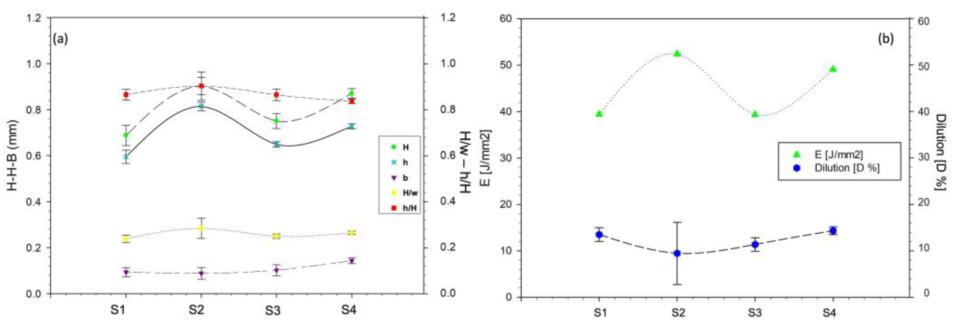
  • The measured geometrical features were directly correlated with the process parameters and the laser energy input (E): the higher the laser energy input, the better the dilution of the clad.
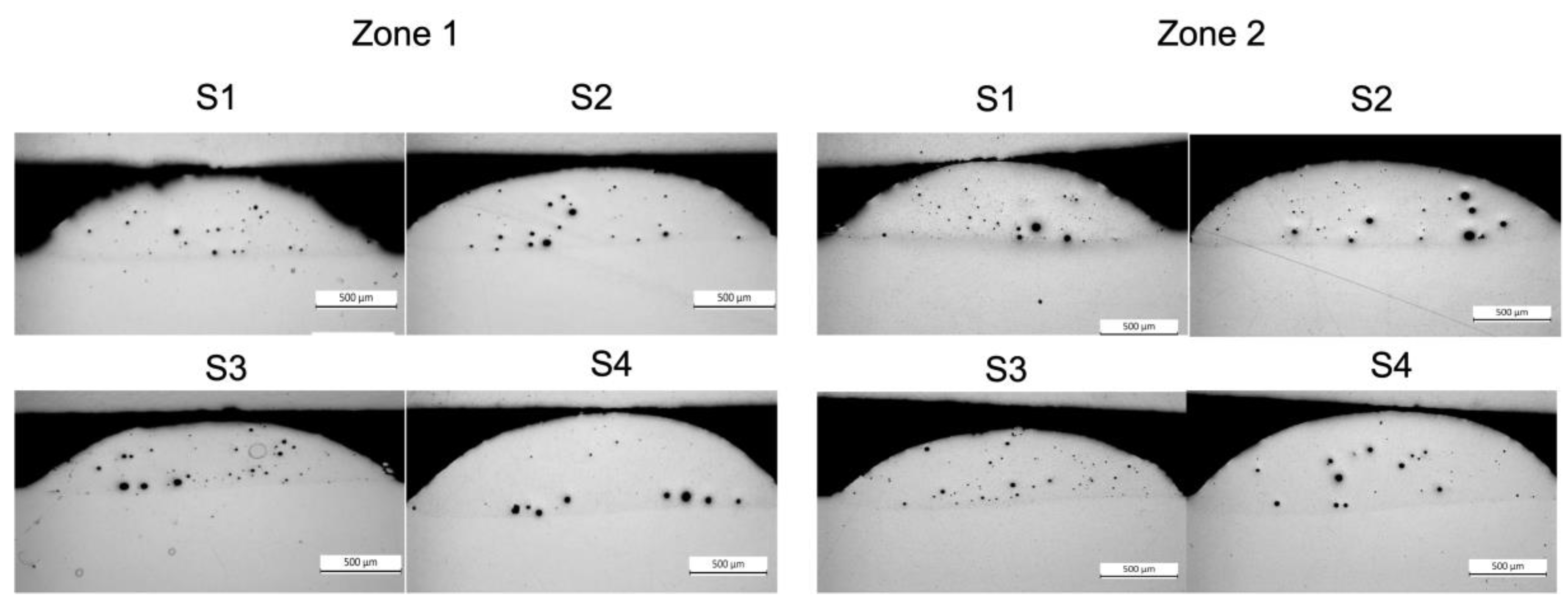
  • Porosities were identified across all samples, regardless of the investigated process parameters. Porosity was quantitatively evaluated by image analysis, and the density of the clad concerning the employed sets of deposition was estimated. More than 99.1% of the theoretical full-density material was reached with a 0.9% maximum porosity. These results show that the adopted parameters can perform a highly dense part with less than 1% of pores across the deposited tracks.
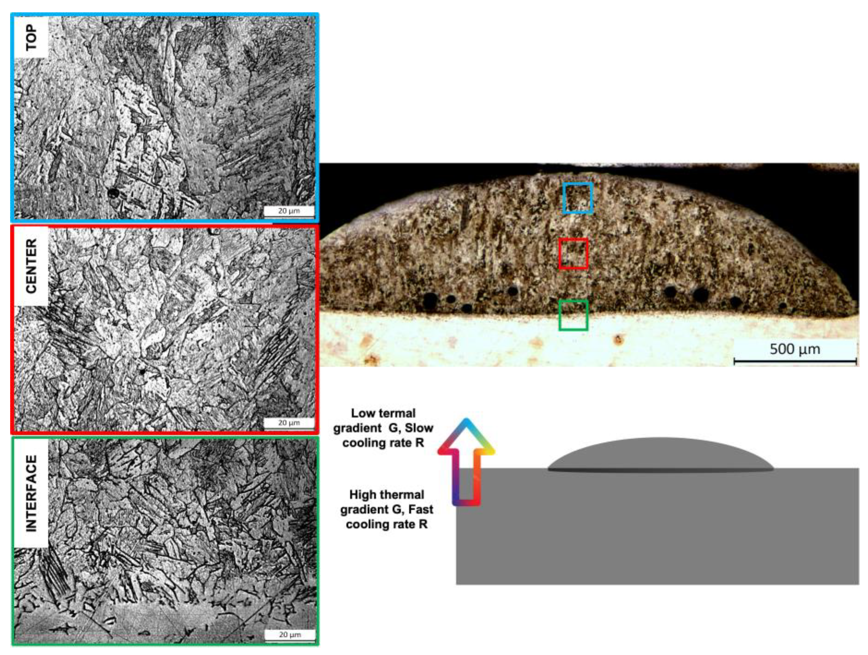
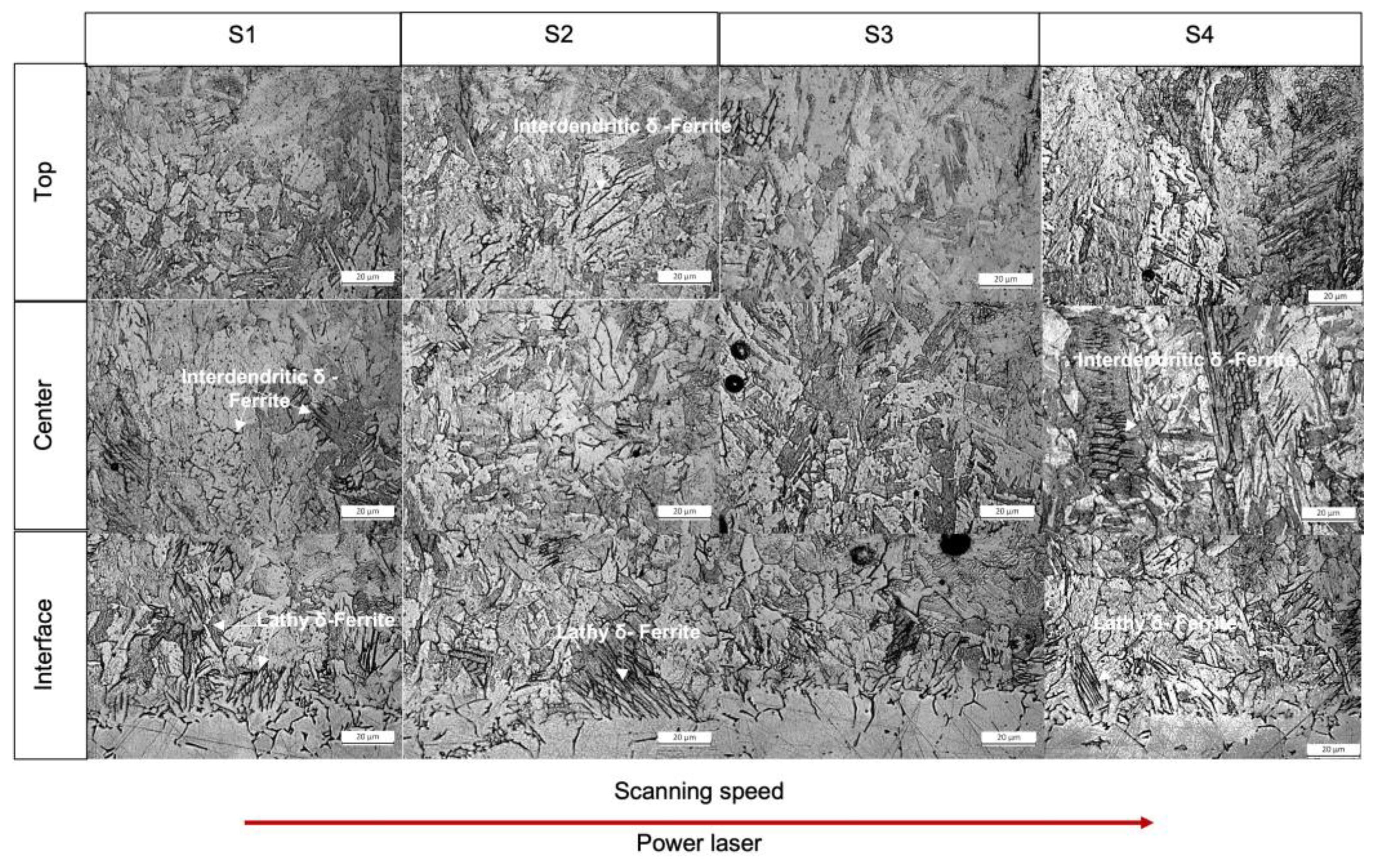
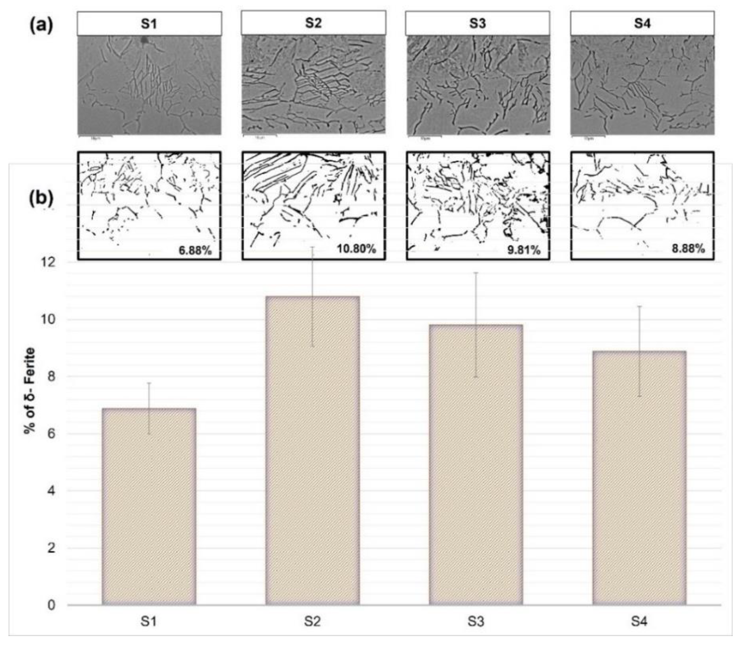
  • The microstructure of the samples is highly correlated with the experienced cooling rate. In general, the size of the martensitic matrix changes with the cooling rate across the different zones of the deposition cross-section, being finer and with a higher amount of δ-ferrite near the substrate-track interface while gradually coarsening moving to the top of the clads.
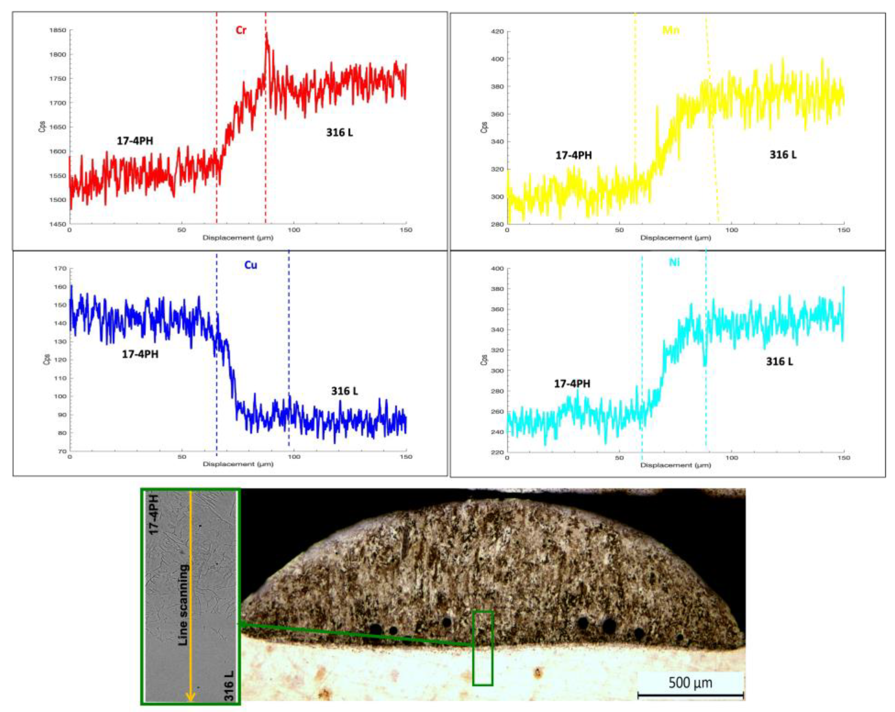
  • Chemical dilution analysis performed by SEM/EDS showed a remarkable but smooth variation in the Cr, Mn, and Ni contents across the interface, highlighting the appropriate dilution that occurred during the DED depositions.
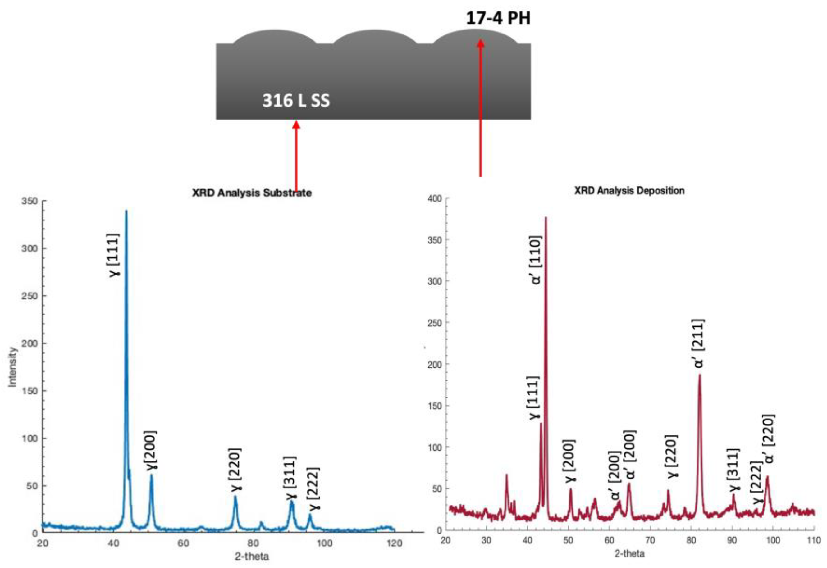
  • XRD patterns showed the presence of peaks of martensite (α’) and austenite (γ), the last revealed in the diffraction patterns but belonging to the substrate. No peaks of δ-ferrite were identified because they were confused with the ones of α’-martensite, surely predominant in the microstructure of the clad.
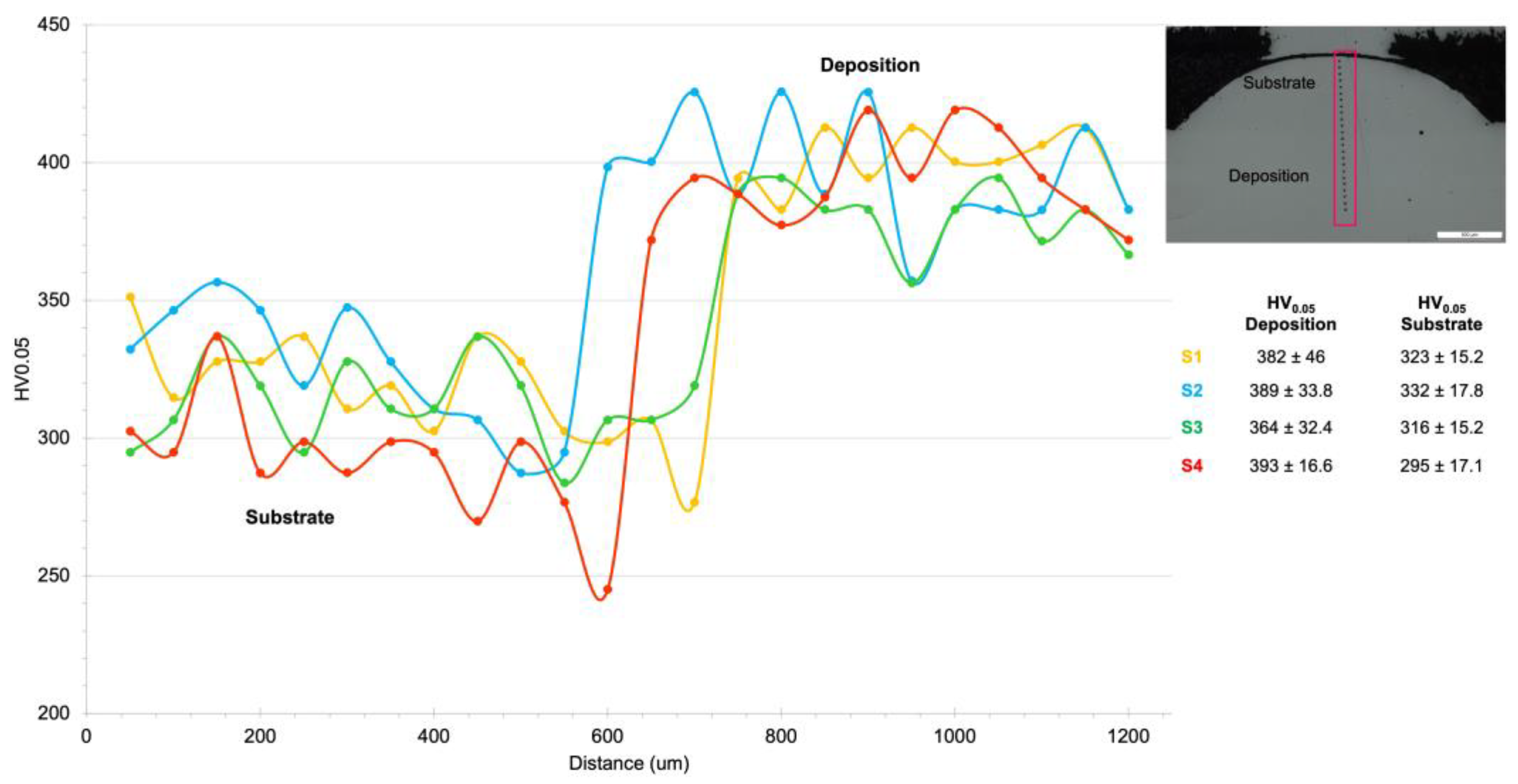
  • Microhardness profiles showed a steep increase in hardness across the substrate-track interface, even though negative drops in microhardness were detected and ascribed to the presence of a significant amount of δ-ferrite near this zone.
Additional investigations will be performed to optimize the sets of process parameters selected and analyzed in this work. Moreover, optimized strategies of post-building heat treatments are under investigation with the aim of better homogenizing the microstructure and increasing the mechanical properties of 17-4 PH clads deposited via DED.

Author Contributions

Data curation, C.M.; Formal analysis, C.M. and M.M.; Funding acquisition, M.M. and A.F. (Alessandro Fortunato); Investigation, C.M. and M.M.; Methodology, C.M., M.M., A.F. (Annalisa Fortini) and A.F. (Alessandro Fortunato); Resources, M.M. and A.F. (Alessandro Fortunato); Supervision, M.M. and A.F. (Alessandro Fortunato); Validation, C.M. and M.M.; Visualization, C.M. and M.M.; Writing—original draft, C.M.; Writing—review and editing, M.M., A.F. (Annalisa Fortini) and A.F. (Alessandro Fortunato). All authors have read and agreed to the published version of the manuscript.

Funding

This work was supported by the BiRex Corporation (Project AN-MEC—L’Additive Manufacturing nella filiera produttiva dell’industria meccanica: dallo sviluppo del processo alla definizione del business model per la produzione di nuovi componenti, CUP C41J20000030008). This research was also funded by the University Found for the Scientific Research (FAR) Application Id n. 766721 of the University of Ferrara (Italy).

Institutional Review Board Statement

Not applicable.

Informed Consent Statement

Not applicable.

Data Availability Statement

The authors confirm that the processed data supporting the findings of this study are available within the article. The raw data required to reproduce these findings cannot be shared as the data form part of an ongoing study.

Acknowledgments

The authors wish to acknowledge Paolo Ferrucci for his help in fabricating the samples studied in this investigation.

Conflicts of Interest

The authors declare no conflict of interest.

References

  1. ASTM International. Standard Guide for Directed Energy Deposition of Metals; ASTM International: West Conshohocken, PA, USA, 2016; pp. 1–22. [Google Scholar] [CrossRef]
  2. Mahamood, R.M. Laser Metal Deposition of Metals and Alloys; Springer: Cham, Switzerland, 2017; pp. 93–118. [Google Scholar] [CrossRef]
  3. Sreekanth, S. Laser-Directed Energy Deposition: Influence of Process Parameters and Heat-Treatments. Doctoral Dissertation, University West, Trollhättan, Sweden, 2020. [Google Scholar]
  4. Murr, L.E.; Martinez, E.; Hernandez, J.; Collins, S.; Amato, K.N.; Gaytan, S.M.; Shindo, P.W. Microstructures and properties of 17-4 PH stainless steel fabricated by selective laser melting. J. Mater. Res. Technol. 2012, 1, 167–177. [Google Scholar] [CrossRef] [Green Version]
  5. Cheruvathur, S.; Lass, E.A.; Campbell, C.E. Additive Manufacturing of 17-4 PH Stainless Steel: Post-processing Heat Treatment to Achieve Uniform Reproducible Microstructure. Miner. Met. Mater. Soc. ASM Int. 2015, 68, 930–942. [Google Scholar] [CrossRef]
  6. Bayode, A.; Pityana, S.; Akinlabi, E.T.; Shongwe, M.B. Effect of scanning speed on laser deposited 17-4PH stainless steel. In Proceedings of the 2017 8th International Conference on Mechanical and Intelligent Manufacturing Technologies, ICMIMT 2017, Cape Town, South Africa, 3–6 February 2017; pp. 1–5. [Google Scholar] [CrossRef]
  7. Wang, T.; Zhu, Y.Y.; Zhang, S.Q.; Tang, H.B.; Wang, H.M. Grain morphology evolution behavior of titanium alloy components during laser melting deposition additive manufacturing. J. Alloys Compd. 2015, 632, 505–513. [Google Scholar] [CrossRef]
  8. Ma, J.; Atabaki, M.M.; Liu, W.; Pillai, R.; Kumar, B.; Vasudevan, U.; Kovacevic, R. Laser-based welding of 17-4 PH martensitic stainless steel in a tubular butt joint configuration with a built-in backing bar. Opt. Laser Technol. 2016, 82, 38–52. [Google Scholar] [CrossRef] [Green Version]
  9. Bayode, E.; Akinlabi, T.; Pityana, S. Microstructure and microhardness of 17-4 PH stainless steel made by Laser metal deposition. Lect. Notes Eng. Comput. Sci. 2016, 2226, 812–814. [Google Scholar]
  10. Caballero, A.; Ding, J.; Ganguly, S.; Williams, S. Wire + Arc Additive Manufacture of 17-4 PH stainless steel: Effect of different processing conditions on microstructure, hardness, and tensile strength. J. Mater. Process. Technol. 2019, 268, 54–62. [Google Scholar] [CrossRef]
  11. Rafi, H.K.; Pal, D.; Patil, N.; Starr, T.L.; Stucker, B.E. Microstructure and Mechanical Behavior of 17-4 Precipitation Hardenable Steel Processed by Selective Laser Melting. J. Mater. Eng. Perform. 2014, 23, 4421–4428. [Google Scholar] [CrossRef]
  12. Facchini, L.; Vicente, N.; Lonardelli, I.; Magalini, E.; Robotti, P.; Molinari, A. Metastable austenite in 17-4 precipitation-hardening stainless steel produced by selective laser melting. Adv. Eng. Mater. 2010, 12, 184–188. [Google Scholar] [CrossRef]
  13. Hu, Z.; Zhu, H.; Zhang, H.; Zeng, X. Experimental investigation on selective laser melting of 17-4PH stainless steel. Opt. Laser Technol. 2017, 87, 17–25. [Google Scholar] [CrossRef]
  14. Auguste, P.; Mauduit, A.; Fouquet, L.; Pillot, S. Study on 17-4 PH stainless steel produced by selective laser melting. UPB Sci. Bull. Ser. B Chem. Mater. Sci. 2018, 80, 197–210. [Google Scholar]
  15. Steponavičiūtė, A.; Selskienė, A.; Stravinskas, K.; Borodinas, S.; Mordas, G. 17-4 PH stainless-steel as a material for high resolution laser metal deposition. Mater. Today Proc. 2021, 52, 2268–2272. [Google Scholar] [CrossRef]
  16. Yu, Z.; Zheng, Y.; Chen, J.; Wu, C.; Xu, J.; Lu, H.; Yu, C. Effect of laser remelting processing on microstructure and mechanical properties of 17-4 PH stainless steel during laser direct metal deposition. J. Mater. Process. Technol. 2020, 284, 116738. [Google Scholar] [CrossRef]
  17. Adeyemi, A.A.; Akinlabi, E.; Mahamood, R.M.; Sanusi, K.O.; Pityana, S.; Tlotleng, M. Influence of laser power on the microstructure of laser metal deposited 17-4 PH stainless steel. IOP Conf. Ser. Mater. Sci. Eng. 2017, 225, 012028. [Google Scholar] [CrossRef] [Green Version]
  18. Mathoho, I.; Akinlabi, E.; Arthur, N.; Tlotleng, M. Impact of DED process parameters on the metallurgical characteristics of 17-4 PH SS deposited using DED. CIRP J. Manuf. Sci. Technol. 2020, 31, 450–458. [Google Scholar] [CrossRef]
  19. Liu, W.; Ma, J.; Atabaki, M.M.; Pillai, R.; Kumar, B.; Vasudevan, U.; Sreshta, H.; Kovacevic, R. Hybrid Laser-arc Welding of 17-4 PH Martensitic Stainless Steel. Lasers Manuf. Mater. Process. 2015, 2, 74–90. [Google Scholar] [CrossRef] [Green Version]
  20. De Oliveira, U.; Ocelík, V.; De Hosson, J. Analysis of coaxial laser cladding processing conditions. Surf. Coat. Technol. 2005, 197, 127–136. [Google Scholar] [CrossRef]
  21. Lin, P.-Y.; Shen, F.-C.; Wu, K.-T.; Hwang, S.-J.; Lee, H.-H. Process optimization for directed energy deposition of SS316L components. Int. J. Adv. Manuf. Technol. 2020, 111, 1387–1400. [Google Scholar] [CrossRef]
  22. Shin, S.; Kwon, S.-M.; Kim, C.; Lee, J.; Hwang, J.H.; KIm, H. Optimization of Direct Energy Deposition of 304L Stainless Steel through Laser Process Parameters. J. Weld. Join. 2021, 39, 182–188. [Google Scholar] [CrossRef]
  23. Dass, A.; Moridi, A. State of the art in directed energy deposition: From additive manufacturing to materials design. Coatings 2019, 9, 418. [Google Scholar] [CrossRef] [Green Version]
  24. Rovatti, L.; Lemke, J.N.; Colombo, M.; Stejskal, O.; Vedani, M. Effetti della diluizione sulla microstruttura e comportamento ad usura di una lega Fe-C-B-Cr-Mo. Metall. Ital. 2015, 107, 15–22. [Google Scholar]
  25. Gu, H.; Gong, H.; Pal, D.; Rafi, K.; Starr, T.; Stucker, B. Influences of Energy Density on Porosity and Microstructure of Selective Laser Melted 17-4PH Stainless Steel. In 2013 International Solid Freeform Fabrication Symposium; University of Texas at Austin: Austin, TX, USA, 2013. [Google Scholar]
  26. Ferro, P.; Meneghello, R.; Savio, G.; Berto, F. A modified volumetric energy density–based approach for porosity assessment in additive manufacturing process design. Int. J. Adv. Manuf. Technol. 2020, 110, 1911–1921. [Google Scholar] [CrossRef]
  27. Peng, L.; Taiping, Y.; Sheng, L.; Dongsheng, L.; Qianwu, H.; Weihao, X.; Xiaoyan, Z. Direct laser fabrication of nickel alloy samples. Int. J. Mach. Tools Manuf. 2005, 45, 1288–1294. [Google Scholar] [CrossRef]
  28. Weaver, J.S.; Whiting, J.; Tondare, V.; Beauchamp, C.; Peltz, M.; Tarr, J.; Phan, T.Q.; Donmez, M.A. The effects of particle size distribution on the rheological properties of the powder and the mechanical properties of additively manufactured 17-4 PH stainless steel. Addit. Manuf. 2021, 39, 101851. [Google Scholar] [CrossRef]
  29. Nezhadfar, P.; Burford, E.; Anderson-Wedge, K.; Zhang, B.; Shao, S.; Daniewicz, S.; Shamsaei, N. Fatigue crack growth behavior of additively manufactured 17-4 PH stainless steel: Effects of build orientation and microstructure. Int. J. Fatigue 2019, 123, 168–179. [Google Scholar] [CrossRef]
  30. Feng, Z. The Lattice Parameter of Gamma Iron and Iron-Chromium Alloys. Doctoral Dissertation, Case Western Reserve University, Cleveland, OH, USA, 2015. [Google Scholar]
  31. Pham, D.T.; Gault, R.S. A comparison of rapid prototyping technologies. Int. J. Mach. Tools Manuf. 1998, 38, 1257–1287. [Google Scholar] [CrossRef]
  32. Erfanmanesh, M.; Abdollah-Pour, H.; Mohammadian-Semnani, H.; Shoja-Razavi, R. An empirical-statistical model for laser cladding of WC-12Co powder on AISI 321 stainless steel. Opt. Laser Technol. 2017, 97, 180–186. [Google Scholar] [CrossRef]
  33. Sreekanth, S.; Ghassemali, E.; Hurtig, K.; Joshi, S. Effect of Direct Energy Deposition Process Parameters. Metals 2020, 10, 96. [Google Scholar] [CrossRef] [Green Version]
  34. Badi, L. Effect of Process Parameters on the Quality of 17-4 PH Samples Produced by Directed Energy Deposition; Politecnico di Torino: Torino, Italy, 2021. [Google Scholar]
  35. Zai, L.; Zhang, C.; Wang, Y.; Guo, W.; Wellmann, D.; Tong, X.; Tian, Y. Laser powder bed fusion of precipitation-hardened martensitic stainless steels: A review. Metals 2020, 10, 255. [Google Scholar] [CrossRef] [Green Version]
  36. Ozsoy, A.; Yasa, E.; Keles, M.; Tureyen, E.B. Pulsed-mode Selective Laser Melting of 17-4 PH stainless steel: Effect of laser parameters on density and mechanical properties. J. Manuf. Process. 2021, 68, 910–922. [Google Scholar] [CrossRef]
  37. Herzog, D.; Seyda, V.; Wycisk, E.; Emmelmann, C. Additive manufacturing of metals. Acta Mater. 2016, 117, 371–392. [Google Scholar] [CrossRef]
  38. Balajaddeh, M.B.; Naffakh-Moosavy, H. Pulsed Nd:YAG laser welding of 17-4 PH stainless steel: Microstructure, mechanical properties, and weldability investigation. Opt. Laser Technol. 2019, 119, 105651. [Google Scholar] [CrossRef]
  39. Ziewiec, A.; Zielińska-Lipiec, A.; Kowalska, J. Microstructure Characterization of Welds in X5CrNiCuNb16-4 Steel in Overaged Condition. Adv. Mater. Sci. 2019, 19, 57–69. [Google Scholar] [CrossRef] [Green Version]
  40. Irizalp, S.; Köroğlu, B. Effect of high-energy laser welding parameters on the microstructure and mechanical properties of 304 stainless steel. Dokuz Eylul Univ. Fac. Eng. J. Sci. Eng. 2021, 23, 179–194. [Google Scholar] [CrossRef]
Figure 1. ABB laser robot with 6 nozzle heads used to perform the DED process.
Coatings 13 00636 g001
Figure 2. Scheme of the cross-section of a track and measured geometrical features.
Coatings 13 00636 g002
Figure 3. Example of single-track DED depositions: sampling positions along the tracks are highlighted with a “X”.
Coatings 13 00636 g003
Figure 4. (a) Geometrical features of the cross-sections and (b) laser energy input (E) values against dilution (D) for each set.
Coatings 13 00636 g004
Figure 5. Unetched representative micrographs of the cross sections of track A for the four sets of parameters (S1–S4) in the two different zones (Zone 1, Zone 2).
Coatings 13 00636 g005
Figure 6. (al) Microstructures of the deposition revealed with different etching strategies: the corresponding etching procedure is reported above each micrograph.
Coatings 13 00636 g006
Figure 7. Microstructure of the AISI 316L substrate electrolytically etched in 10% oxalic acid solution for 240 s and 6 V.
Coatings 13 00636 g007
Figure 8. Evolution of microstructure from the clad/substrate interface up to the top of the clad in sample S4_A_2.
Coatings 13 00636 g008
Figure 9. Evolution of microstructure across track A, zone 2, for each set of process parameters (S1–S4).
Coatings 13 00636 g009
Figure 10. (a) SEM micrographs revealing the presence of δ-ferrite near the interface zone across track A, zone 2, for each set of process parameters (S1–S4); (b) % of δ-ferrite measured across the interface by image analysis.
Coatings 13 00636 g010
Figure 11. Chemical dilution: SEM/EDS line maps of elements in sample S4_A_2.
Coatings 13 00636 g011
Figure 12. XRD patterns performed on sample S4_A_2.
Coatings 13 00636 g012
Figure 13. Vickers microhardness profiles.
Coatings 13 00636 g013
Table 1. Chemical composition [wt. %] of the 17-4 PH powder employed for the DED single-track depositions.
ElementSiCrNiCuNbMnPSFe
Chemical composition [wt. %]0.43 15.28 4.493.390.270.500.0190.0003Bal.
Table 2. Results of preliminary investigations.
Power (p) [W]ReplicasScanning Speed (s) [mm/s]Power Feed Rate (fr) [g/min]Dilution (D %) [%]Height of the Clad H [mm]Defects Presence
(Sum of Points in Accordance with Low Porosity 0.5, Medium Porosity 1, High Porosity 2 and Detachment 4)
1300A B C106.729.2406.01.5
1300A B C1013.46.6672.34.0
1300A B C1020.02.9883.07.0
1300A B C156.744.2259.31.0
1300A B C1513.414.2447.71.0
1130A B C1520.01.3612.37.5
1300A B C206.751.7194.70
1300A B C2013.419.5344.72.0
1300A B C2020.031.8302.33.0
1730A B C106.739.4403.02.5
1730A B C1013.48.0749.05.0
1730A B C1020.01.81063.37.5
1730A B C156.748.4290.32.5
1730A B C1513.416.2518.72.0
1730A B C1520.04.2705.37.5
1730A B C206.752.6236.31.5
1730A B C2013.426.9377.32.5
1730A B C2020.013.0473.73.0
2160A B C106.731.2371.01.0
2160A B C1013.429.5666.35.0
2160A B C1020.05.4925.07.0
2160A B C156.763.2274.70
2160A B C1513.440.3424.71.0
2160A B C1520.020.3575.73.0
2160A B C206.757.9256.70
2160A B C2013.433.4409.02.0
2160A B C2020.011.1556.03.5
Table 3. Combinations of process parameters settled to perform DED depositions [S1: set1, S2: set2, S3: set3, S4: set4].
Set Power (p)
[W]
Scanning Speed (s)
[mm/s]
Power Feed Rate (fr)
[g/min]
Laser Energy Input (E)
[J/mm2]
S113001513.439.4
S217301513.452.4
S317302020.039.3
S421602020.049.1
Table 4. Investigated combinations of etching strategies.
EtchantTime and Voltage
Vilella’s15 s
Vilella’s30 s
Fry’s3 s
Fry’s5 s
Kalling’s2 s
Kalling’s5 s
Beraha’s25 s
Oxalic Acid240 s, 6 V
Oxalic Acid + Beraha’s300 s, 6 V + 60 s
Kalling’s10 s
Fry’s5 s
Vilella’s90 s
Fry’s + Marble’s5 s + 15 s
Ralph’s45 s
Ralph’s + Oxalic Acid20 s + 120 s, 6 V
Marble’s10 s
Ralph’s + Oxalic Acid + Kalling’s20 s + 120 s, 6 V + 5 s
Table 5. Geometrical features measures of the samples performed [A: track A, B: track B, C: track C], [1: zone 1, 2: zone 2]. Avg. is the average value, and Std. is the standard deviation.
SampleH [mm]h [mm]w [mm]b [mm]H/wh/H
S1_A_10.7040.5942.9270.1100.2410.844
S1_B_10.6540.5732.9120.0810.2250.876
S1_C_10.6990.5902.8670.1090.2440.844
S1_A_20.6390.5782.8190.0610.2270.905
S1_B_20.6690.5822.9370.0870.2280.870
S1_C_20.7610.6522.8390.1090.2680.857
Avg. Std.0.688
± 0.044
0.595
± 0.029
2.884
± 0.049
0.093
± 0.020
0.238
± 0.016
0.865
± 0.023
S2_A_10.7780.6833.2310.0950.2410.878
S2_B_10.7870.6863.2820.1010.2400.872
S2_C_10.8220.6993.2010.1230.2570.850
S2_A_21.0260.9373.0290.0890.3390.913
S2_B_20.9790.9233.1160.0560.3140.943
S2_C_21.0180.9543.2040.0640.3180.937
Avg. Std.0.902
± 0.062
0.814
± 0.018
3.177
± 0.090
0.088
± 0.025
0.284
± 0.044
0.902
± 0.038
S3_A_10.7130.6412.9590.0720.2410.899
S3_B_10.7650.6623.0030.1030.2550.865
S3_C_10.7540.6553.0410.0990.2480.869
S3_A_20.7220.6293.0220.0930.2390.871
S3_B_20.7440.6453.0100.0990.2470.867
S3_C_20.8020.6583.0050.1440.2670.820
Avg. Std.0.750
± 0.032
0.648
± 0.012
3.007
± 0.027
0.102
± 0.024
0.249
± 0.010
0.864
± 0.025
S4_A_10.8430.7133.2530.1300.2590.846
S4_B_10.8580.7173.3090.1410.2590.836
S4_C_10.8700.7283.3090.1420.2630.837
S4_A_20.8670.7303.3090.1370.2620.842
S4_B_20.8750.7343.2980.1410.2650.839
S4_C_20.9070.7423.2770.1650.2770.818
Avg. Std.0.870
± 0.021
0.727
± 0.011
3.293
± 0.023
0.143
± 0.012
0.264
± 0.007
0.836
± 0.010
Table 6. Semiquantitative porosity measurements across the depositions: average values and the standard deviation are also reported.
SampleAc [mm2]Am [mm2]Ac + Am [mm2]Ap [mm2]Ap%
[%]
ρ
[g/cm3]
D%
[%]
S1_A_11.2000.2021.4020.0070.4727.76414.408
S1_B_11.1390.2041.3430.0040.30215.190
S1_C_11.1790.2011.3800.0080.59614.565
S1_A_21.1530.1571.3100.0050.35611.985
S1_B_21.1850.1641.3490.0070.53712.157
S1_C_21.3140.2381.5520.0080.50115.335
Avg. Std.1.195
± 0.062
0.194
± 0.030
1.389
± 0.086
0.006 ± 0.0020.461
± 0.111
13.940
± 1.491
S2_A_11.5630.2661.8290.0100.5247.73614.543
S2_B_11.5900.3001.8900.0170.90515.873
S2_C_11.6300.3151.9450.0180.94916.195
S2_A_22.1680.0892.2570.0130.5923.943
S2_B_22.1080.0602.1680.0190.8792.768
S2_C_22.2500.0782.3280.0261.1103.351
Avg. Std.1.885
± 0.322
0.185
± 0.121
2.070
± 0.208
0.017 ± 0.0060.827
± 0.224
9.446
± 6.706
S3_A_11.3500.1701.5200.0050.3407.76411.184
S3_B_11.4280.1371.5650.0050.3428.754
S3_C_11.4100.1731.5830.0100.65910.929
S3_A_21.3620.1881.5500.0120.77412.129
S3_B_21.3620.1881.5500.0010.04112.129
S3_C_21.3850.2071.5920.0090.59413.003
Avg. Std.1.383
± 0.031
0.177
± 0.024
1.560
± 0.026
0.007
± 0.004
0.458
± 0.268
11.355
± 1.476
S4_A_11.6590.2871.9460.0170.8907.73114.748
S4_B_11.6600.2691.9290.0261.35313.945
S4_C_11.7450.2792.0240.0170.81513.785
S4_A_21.6470.2991.9460.0140.70715.370
S4_B_21.7320.2331.9650.0120.60614.900
S4_C_21.7680.2682.0360.0190.91713.160
Avg. Std.1.702
± 0.052
0.273
± 0.023
1.974
± 0.045
0.017
± 0.005
0.881
± 0.259
14.318
± 0.824
Disclaimer/Publisher’s Note: The statements, opinions and data contained in all publications are solely those of the individual author(s) and contributor(s) and not of MDPI and/or the editor(s). MDPI and/or the editor(s) disclaim responsibility for any injury to people or property resulting from any ideas, methods, instructions or products referred to in the content.

