Article

Effect of MoO3 Content on Ni3Al-Ag-MoO3 Composite Coating Microstructure and Tribological Properties

1
School of Materials Science and Engineering, Lanzhou University of Technology, Lanzhou 730050, China
2
School of Materials Science and Engineering, Shandong University of Science and Technology, Qingdao 266590, China
3
State Key Laboratory of Solid Lubrication, Lanzhou Institute of Chemical Physics, Chinese Academy of Sciences, Lanzhou 730000, China
*
Author to whom correspondence should be addressed.
Coatings 2023, 13(3), 624; https://doi.org/10.3390/coatings13030624
Submission received: 15 February 2023 / Revised: 7 March 2023 / Accepted: 13 March 2023 / Published: 15 March 2023
(This article belongs to the Special Issue Friction, Wear, Lubrication and Mechanics of Surfaces and Interfaces)

Abstract

:
In order to provide effective solid lubrication to Ni3Al coating, 10 wt.% Ag and different amounts of MoO3 solid lubricant were mechanically mixed with the SHSed Ni3Al powder and sprayed HVOF. Microstructure, mechanical properties, and tribological behavior from 25 °C to 800 °C of the coatings were studied, and the basic wear mechanisms were explored and discussed as well. Results show that the hardness and adhesive bonding strength of the coatings are slightly decreased, while there is little effect on the microstructure and mechanical properties of the Ni3Al-based composite coating when the content of MoO3 additive in the feedstock powder is lower than 15 wt.%. The composite coating formed by feedstock powder containing 15 wt.% MoO3 additive also presents excellent anti-friction and anti-wear performance from 25 °C to 800 °C, especially at 800 °C, where a complete, smooth, and thicker lubricating film comprised of NiO, Al2O3, MoO3, and Ag2MoO4 was formed, which reduced the friction coefficient (COF) and wear rate (WR) to the lowest value of 0.36 and 6.03 × 10⁻⁵ mm3/(Nm), respectively. An excessive amount of MoO3 in the feedstock powder (20 wt.%) results in inferior interlayer bonding of the formed coating, and the coating is more prone to delamination and abrasive wear above 200 °C.

1. Introduction

Due to its low density (7.5 g/cm3), high hardness, high thermal conductivity, high melting point (1668 K), excellent oxidation and corrosion resistance, as well as high strength at elevated temperatures, Ni3Al intermetallic compound has been considered a promising structural parts material of aviation, aerospace, and other high-tech industries [1,2]. However, polycrystalline Ni3Al intermetallic compound possesses poor tribological performance, which severely restricts their practical applications in harsh conditions of high load, high sliding speed, and high temperature [3]. Solid lubricant additives are a direct and effective solution to improve the anti-friction and anti-wear performance of the Ni3Al intermetallic compound [4]. Zhai et al. [5] studied the tribological behavior of Ni3Al-based composite with graphene nanoplatelets (GNPs) from room temperature to 600 °C, the composite with GNPs possessed lower and more steady COFs and lower WRs from room temperature to 400 °C (0.21–0.26 and 4.1–5.3 × 10⁻⁶ mm3/Nm, respectively) because of the slippage of laminated sheets between GNPs and refinement of grains, while the GNPs oxidized and lost their lubrication ability above 400 °C. Zhu et al. [6] prepared Ni3Al-BaMoO4 composite by powder metallurgy technique and found that the composite exhibited low COF (0.26) and WR (1.1 × 10⁻⁵ mm3/Nm) above 400 °C due to the lubricating effect of BaMoO4. In contrast, the composite exhibited inferior tribological properties with high COF above 0.6 and WR above 10−4 mm3/Nm below 400 °C. It seems that the range of lubrication temperature of a single solid lubricant is very limited, and no solid lubricant can provide effective lubrication from low to high temperatures. For instance, molybdenum disulfide and graphite are effective from room temperature to 400 °C, but otherwise, they lose their lubrication properties due to inadequate oxidation resistance [7,8]. Fluorides (CaF2, BaF2, BaF2/CaF2 eutectics, etc.), oxides (CuO, MoO3, ZnO, WO3, etc.), and inorganic salts (sulfate, molybdate, chromate, tungstate, etc.) lubricate well from 500 °C to 800 °C [9,10].
Researchers have developed a lot of self-lubricating composites using the synergetic lubrication effect of high and low temperature solid lubricants to widen the operating temperature range of self-lubricating composites. Silver is easy to diffuse on the friction surface and forms a lubrication film with low-shear strength by its large diffusion coefficient, resulting in good anti-friction performance [11]. Thus, it has been widely used in conjunction with other high-temperature solid lubricants to provide excellent lubrication over a wider range of temperatures. Zhu et al. [10] prepared Ni3Al-Ag-BaCrO4 and Ni3Al-Ag-BaMoO4 composites by powder metallurgy and found that the continuous lubrication properties of the composites were attributed to the excellent synergistic lubrication effect of silver and inorganic salts. The tribological properties of Ni3Al-based composites with various amounts of WAh (Ag, WS2, and hBN with a weight ratio of 1:1:1) from room temperature to 800 °C were researched by Shi et al. [12], and the results indicated that the tribological behavior of the Ni3Al-based composite strongly related to the content of the WAh additive, and the composite with 15 wt.% WAh showed excellent tribological properties due to the synergetic lubrication of WAh, in which Ag and WS2 played an influential lubrication role at medium and low temperatures, while hBN played a lubrication role at medium and high temperatures.
Lamellar α-MoO3 is a thermodynamically stable phase with a crystallographic anisotropic structure. With weak interlayer binding force, α-MoO3 is easily fractured and interlaminar shear slip occurs in the friction action force during the sliding and is considered to be an excellent solid lubricant. Wang et al. [13] prepared the NiCr-Ag-MoO3 composite by the powder metallurgy method, and the COF and WR of the composite decreased with the increasing temperature and had the lowest COF and WR of 0.23 and 1.35 × 10⁻⁵ mm3/Nm at 700 °C, respectively.
Compared to bulk composites, the substrate of the coating would provide the structural part with good stiffness and strength, and the coating imparts functional performance, such as oxidation, corrosion, and wear resistance. Thus, the additive phases with low hardness or high brittleness in the coatings do not affect the mechanical properties of structural part. In this paper, Ni3Al-Ag-MoO3 composite coatings were deposited by HVOF spraying technology by tailoring the content of MoO3 in the feedstock powder (0, 10, 15, and 20 wt.%), the effects of MoO3 on the microstructure, mechanical properties, and tribological behavior of the coatings in a wide temperature range (25–800 °C) were studied, and synergetic lubrication mechanisms and wear mechanisms of Ni3Al-based solid lubricational coatings at various testing temperatures were also explored.

2. Experimental Procedure

2.1. Materials and Coating Preparation

Commercial Ni, Al, Ag, and MoO3 powders with the size of 50 μm (99.9% purity) were purchased from Shanghai Pantian Powder Material Co., Ltd., (Shanghai, China). The Ni and Al powders with a 3:1 molar ratio were mixed to synthesize the Ni3Al powder with an angular shape using a self-propagating combustion synthesis and crushing; the detailed preparation process has been described in a previous study [14]. Silver powder exhibits an excellent lubrication performance when its content ranges from 1 wt.% to 10 wt.% [15]. Thus, the silver powder was added with a fixed mass fraction of 10%. The Ni3Al-based composite powders with 0, 10, 15, and 20 wt.% of MoO3 (their corresponding coatings are denoted as NAM0, NAM10, NAM15, and NAM20, respectively) were mixed mechanically for 3 h using a three-dimensional eddy current mixing apparatus (TD-2). Then, the mixed composite powders were used as the feedstock powder to fabricate the coatings, and the compositions of the NAM feedstock powder are listed in Table 1 in detail.
The substrate is AISI 310 stainless steel with a size of 20 mm × 20 mm × 5 mm. Prior to spraying, the substrate was sandblasted, washed with alcohol by ultrasonic cleaner for 15 min, and then dried with hot nitrogen. The feedstock powder was dried in an oven for 30 min, and the substrate was preheated at 150–200 °C for 5 min. Then the coating was deposited on AISI 310 stainless steel substrate using a Diamond Jet 2700 high-velocity oxygen fuel spray system (HVOF, Sulzer Metco, Winterthur, Switzerland,) equipped with an IRB 2400/16 robot (ABB, ABB Switzerland Ltd., Turgi, Switzerland). The optimized spray parameters employed are shown in Table 2.

2.2. Tribological Tests

The friction and wear tests on the coatings were performed by a high-temperature ball-on-disk tribometer (HT-1000, Zhong Ke Kai Hua Corporation, Shenzhen, China). The lower disk was the as-sprayed coating specimen (20 mm × 20 mm × 5 mm), and the upper counterpart ball was a commercially obtained Si3N4 ball (Φ6 mm, 1700 HV). Prior to the tribological testing, the as-sprayed coating was successively ground with 400, 1000, and 2000 SiC paper, and polished with diamond paste to get a mirror level surface with roughness (Ra) of approximately 0.3 to 0.5 μm. Both the disk and the ball were ultrasonically cleaned with alcohol by ultrasonic cleaner for 10 min and dried with hot air. Then, the tests were conducted at an applied load of 5 N, a sliding speed of 0.19 m/s, and a duration of 30 min. The test temperatures were 25 °C, 200 °C, 400 °C, 600 °C, and 800 °C. The cross-section profile and wear volume loss of worn surfaces were measured by an MT-500 2-D surface profilometer (Zhong Ke Kai Hua Corporation, China). The WR of the coatings was calculated by W = V/(FS), where W is the WR in mm3/(N·m), V is the wear volume in mm3, F is the applied load in N, and S is the total sliding distance in m. Each friction and wear test was repeated three times to ensure the repeatability of the experimental results, and the average results were reported.

2.3. Characterization

Hardness of the composite coatings was tested by an HV-1000 Vickers hardness tester (Beijing Times Top Technology Co., Ltd., Beijing, China) under a load of 300 g and a dwell time of 10 s. The measurement was carried out at ten locations, and the average value was reported. Porosity of the coatings was calculated by the metallographic method combined with Image Pro-Plus analysis software (6.0, 2006, Media Cybernetics, Inc., Washington, DC, USA). Adhesive bonding strength of the coatings on AISI 310 stainless steel was tested using an AG-10TA universal testing machine (Shimadzu, Tsushima, Japan) under a tensile speed of 2 mm/min and a tension of 20 kN according to ASTM C633 standard. All the adhesive bonding strength values are the average of 3 measurements.
Phase compositions of the coatings were examined using a D/max-2400 X-ray diffractometer (XRD, Rigaku Corporation, Tokyo, Japan) with Cu-Ka radiation at 40 kV and 100 mA over an angular range of 10–90°. Morphologies and element distribution of the coatings, worn tracks, and wear scars were observed by a JSM-6700F field emission scanning electron microscope (SEM) (Japan Electron Optics Laboratory, Tokyo, Japan) equipped with an energy dispersive spectrometer (EDS). Chemical compositions of worn tracks were investigated by an HR800 Raman spectrometer (Renishaw Corporation, London, UK) with an excitation wavelength of 532 nm. Compounds and chemical valence of worn tracks were examined by an X-ray photoelectron spectroscopy (XPS, ESCALAB 250Xi, Shanghai Fel Li Jia Shi Ye Co., Ltd., Shanghai, China), and the Casa analytical software (CasaXPS 2.3.16, 2015, Casa Software Ltd., Wuxi, China) was used to analyze the XPS data.

3. Results

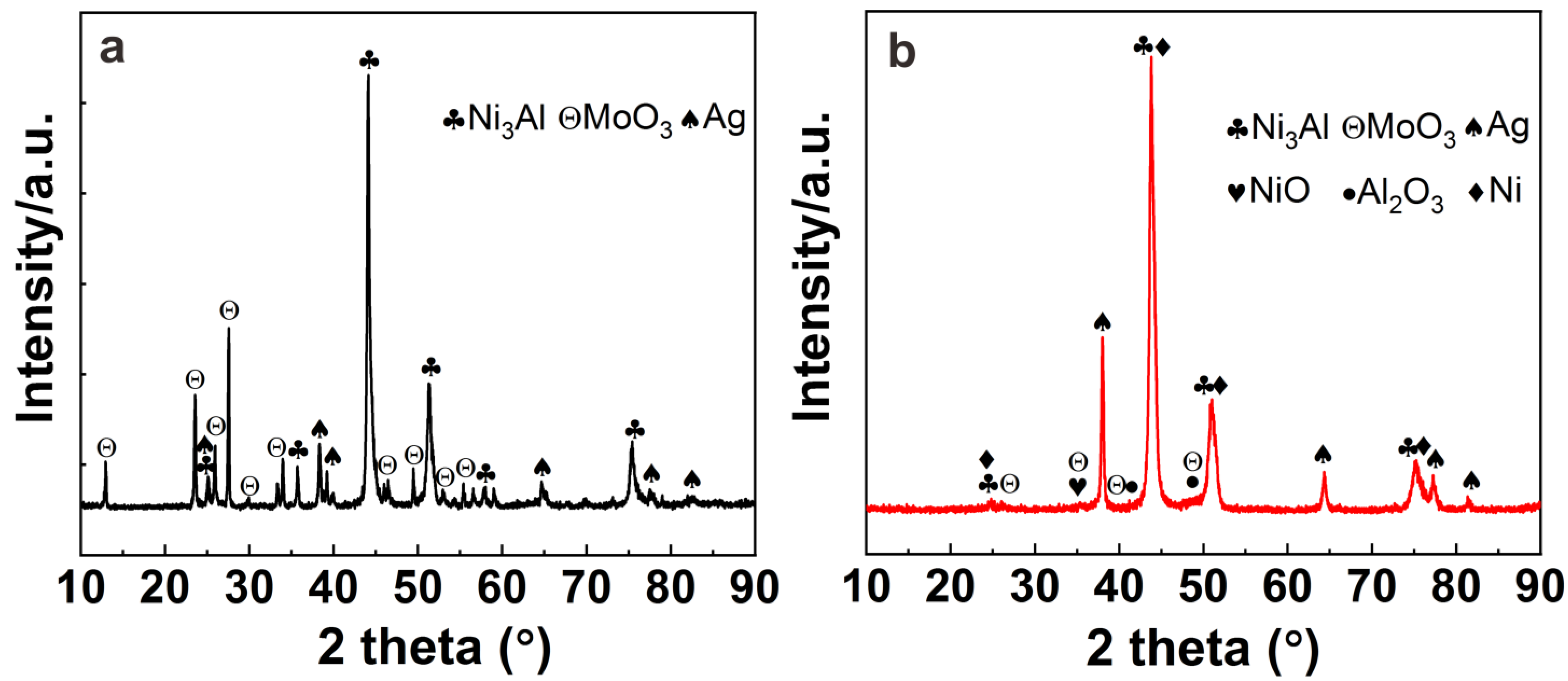
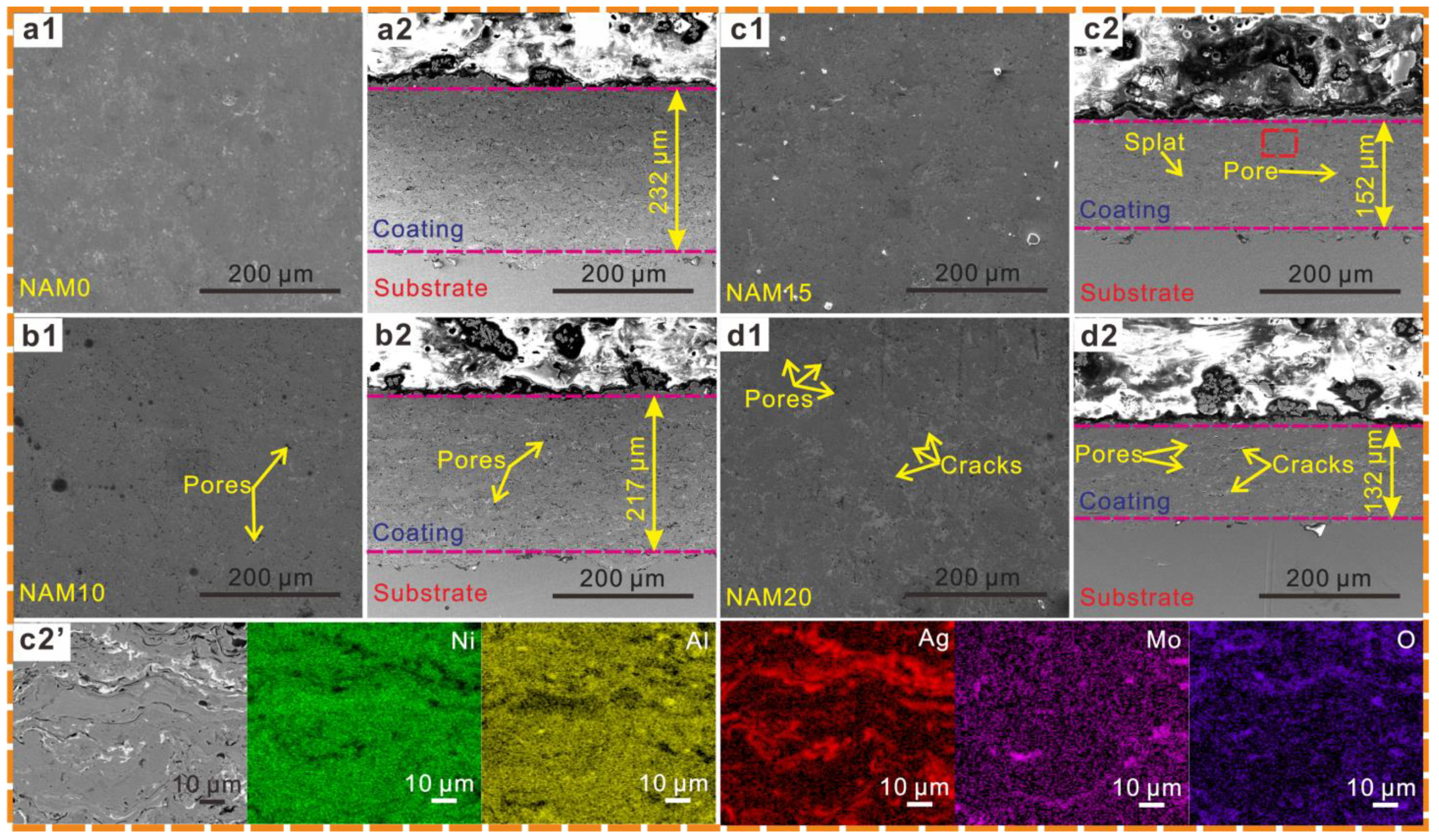
3.1. Microstructures and Mechanical Properties of Coatings

Figure 1 shows the typical XRD results of the NAM15 feedstock powder and corresponding as-sprayed NAM15 coating. The phases of the powder are mainly composed of Ni3Al (PDF 09-0097), Ag (PDF 04-0783), and MoO3 (PDF 05-0508); except for these phases, new phases of NiO (PDF 44-1159), Al2O3 (PDF 26-0031), and Ni (PDF 04-0850) were detected in the coating, which may be attributed to the oxidation of the molten particles during the impinging and stacking in the HVOF spraying process [16], while the diffraction peaks of MoO3 become weaker in the as-sprayed coating.
Figure 2 presents the polished surface and sectional SEM morphologies of the NAM coating formed with various content of MoO3 additive feedstock powder, and the elemental distribution of NAM15 coating. In addition, the mechanical properties of the polished NAM coating are listed in Table 3. All the composite coatings exhibit a typical layered structure caused by the technical characteristics of HVOF spraying. When the amount of MoO3 additive in the feedstock powder is 10 wt.% and 15 wt.%, the corresponding composite coatings have a relatively dense microstructure with small cracks and pores (Figure 2(b1,b2), (c1,c2)), and slightly increased porosity compared to the NAM0 coating (Table 3). However, when MoO3 content in the feedstock powder is further increased to 20 wt.%, a large number of obvious cracks, pores, and delamination were presented in the NAM20 coating (Figure 2(d1,d2)), and the porosity of the NAM20 coating significantly increased to 5.53%. According to XRD and EDS elemental distribution analysis results of NAM15 coating (Figure 1b and Figure 2(c2′)), the light gray phase is Ni3Al, the dark phase is Al2O3 and NiO, the white phase is Ag, and the gray phase which dispersed along the grain boundary of Ag is the MoO3.
As the Vickers hardness and adhesive bonding strength of the NAM composite coatings in Table 3 show, the hardness of the formed coatings slightly decreases from 486.0 ± 9.1 HV to 449.1 ± 14.7 HV when the MoO3 content in the feedstock powder increases from 0 wt.% to 15 wt.%. However, the hardness of the NAM20 coating sharply decreases to 356.8 ± 17.9 HV as the amount of MoO3 in the feedstock powder increases to 20 wt.%. The adhesive bonding strength of the coatings possesses a similar change trend to that of Vickers hardness; it slowly decreases from 59.4 ± 5.4 MPa to 53.1 ± 1.5 MPa when the MoO3 content in the feedstock powder increases from 0 wt.% to 15 wt.% and then decreases to 47.5 ± 4.8 MPa as the MoO3 content in the feedstock powder is increasing to 20 wt.%.

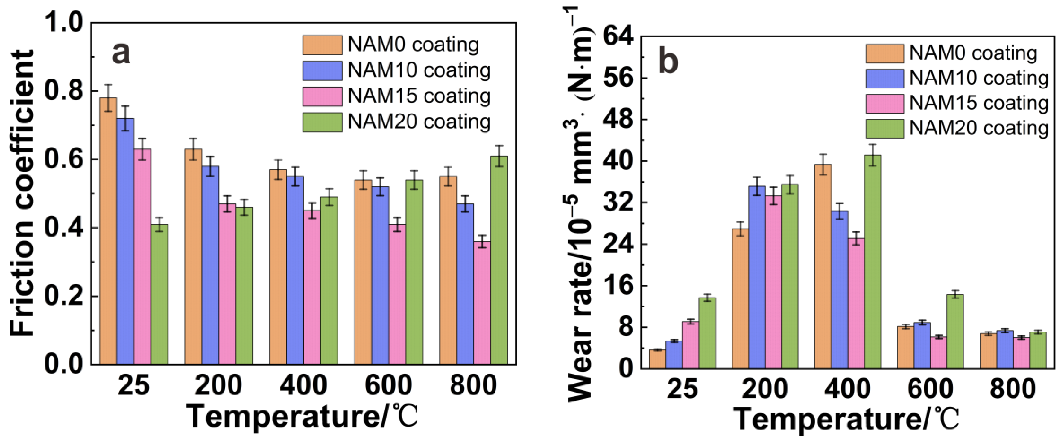
3.2. Tribological Performances of the NAM Coatings over a Wide Temperature Range

Figure 3 shows the variation of COFs and WRs of the NAM coatings formed with various content of MoO3 additive feedstock powder at various temperatures. From Figure 3a, one can see that the COFs of the NAM0, NAM10, and NAM15 coatings slightly decrease as the temperature rises. However, the COF of the NAM20 coating straightly ascends with increasing temperature. At 25 °C and 200 °C, the COFs of the coatings are decreased with the increase in MoO3 content in the feedstock powder. From 400 °C to 800 °C, as the MoO3 content in the feedstock powder rises, the COFs of the formed coatings are firstly decreased followed by an increase, and the difference in COF is more obvious at 600 °C and 800 °C. As a whole, the NAM15 coating formed by feedstock powder containing 15 wt.% MoO3 additives exhibits the best lubricity at all tested temperatures, and its COF ranges from 0.63 to 0.36. As seen in Figure 3b, the WRs of all the coatings firstly increased and then gradually decreased with the raising in temperature, and all coatings have relatively high WRs at 200 °C and 400 °C (above 25 × 10−5 mm3/(Nm)). At 25 °C and 200 °C, the WRs slightly increase with the increase in MoO3 content in the feedstock powder, and the NAM0 coating exhibits the lowest WRs (about 3.63 × 10⁻⁵ mm3/(Nm) at 25 °C and 26.92 × 10⁻⁵ mm3/(Nm) at 200 °C). From 400 °C to 800 °C, the WRs are firstly decreased followed by an increase as the MoO3 content in the feedstock powder increase, and the NAM15 coating exhibits the lowest WR of 25.11 × 10⁻⁵ mm3/(Nm) to 6.03 × 10⁻⁵ mm3/(Nm). While an excessive amount of MoO3 in the feedstock powder (20 wt.%) appears to deteriorate the wear resistance of the formed composite coating at all the test temperatures, the WRs of the NAM20 coating are significantly higher than that of the NAM0 coating, which ranges from 41.15 × 10⁻⁵ mm3/(Nm) to 7.08 × 10⁻⁵ mm3/(Nm) at 25 °C to 800 °C.

3.3. Effect of MoO3 on the Friction Behavior of the NAM Coatings

Figure 4 shows SEM images of the worn tracks of NAM0 composite coating at various temperatures. At 25 °C, the worn track is characterized by a large number of furrows, cracks, and fine wear debris (Figure 4a), suggesting that the main wear mechanisms are abrasive wear and slight brittle fracture. At 200 °C, a lot of flake-like debris and several plastic smearings are distributed on the worn track (Figure 4b), and the wear mechanisms are characterized by adhesive wear and abrasive wear. When the test temperature increases to 400 °C, one can see that the damaged pieces and a larger amount of wear debris appear on the worn track (Figure 4c), illustrating that the wear mechanisms are dominated by fatigue spalling and abrasive wear. The worn tracks are depicted by fatigue cracks, adhesion, fine and slight grooves, and a relatively thin lubrication film at 600 °C and 800 °C (Figure 4d,e), and the main wear mechanisms are dominated by adhesion wear, oxidation wear, and slight abrasive wear.
Figure 5 presents the SEM images of the worn tracks of NAM10, NAM15, and NAM20 coatings at various temperatures. At 25 °C, several plastic smearings and a large number of grooves parallel to the sliding direction are observed on the worn tracks of NAM10 and NAM15 coatings (Figure 5(a1,a2)), which illustrates that the wear mechanisms are dominated by adhesive wear and abrasive wear. Although there is a large amount of fine wear debris scattered on the worn track of the NAM20 coating, the scratches on the worn track are significantly reduced (Figure 5(a3)). It implies that the abrasive wear is reduced for NAM20 coating. At 200 °C, the worn tracks morphologies are similar to that at 25 °C, indicating that the wear mechanisms have not changed (Figure 5(b1–b3)). As the temperature increases to 400 °C and 600 °C, a smooth and thin layer with slight grooves is distributed on the worn track of NAM15 coating (Figure 5(c2,d2)). Nevertheless, the thin layer formed on the worn track of NAM10 coating has low compactness (Figure 5(c1,d1)), and the NAM20 coating is characterized by a large number of cracks, severe delamination, and lots of flaky wear debris of irregular shape (Figure 5(c3,d3)); the dominant wear mechanisms are delamination wear and severe abrasive wear, and this is well consistent with higher COFs and WRs than those of the NAM15 coating. As the temperature further rises to 800 °C, a continuous and complete glaze layer is covered on the worn track of NAM15 coating, and the worn track becomes much smoother (Figure 5(e2)). The mild wear mechanisms and the complete lubricious interface result in noticeable improvement of tribological performance of the NAM15 coating. An obvious glaze layer also appears on the worn track of NAM20 coating; however, obvious cracks and splat delamination are observed on this kind of worn track (Figure 5(e3)).

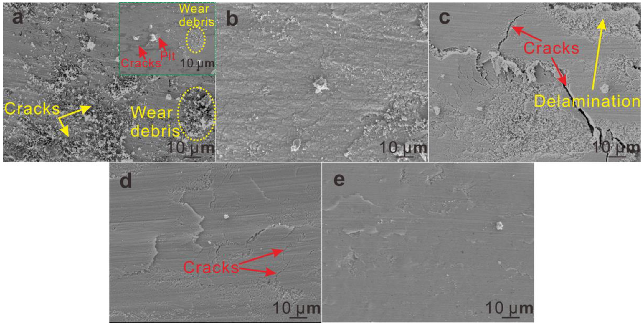
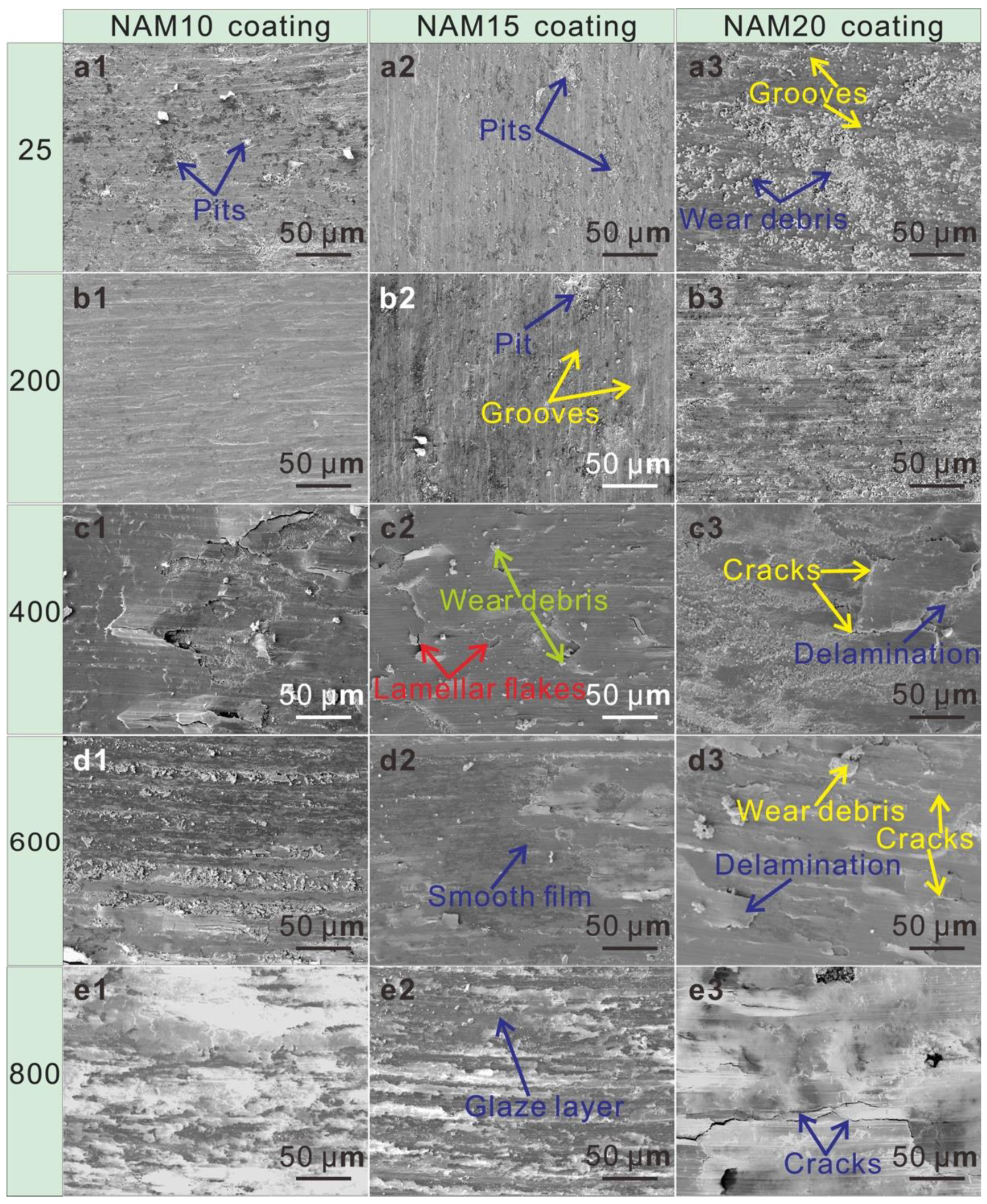
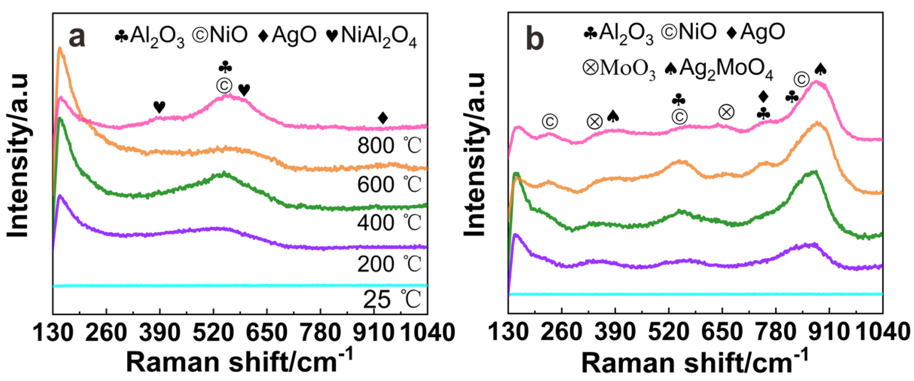
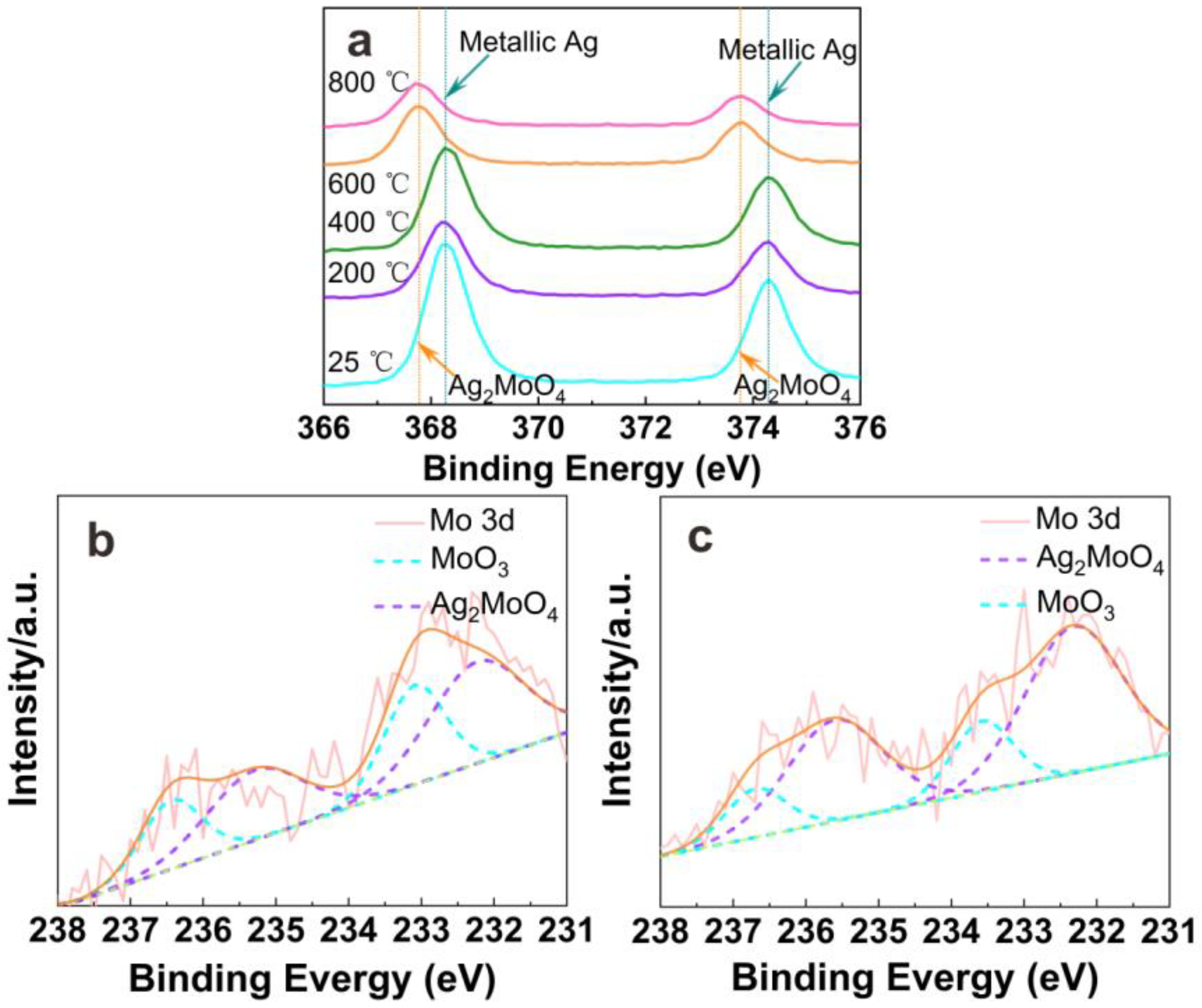
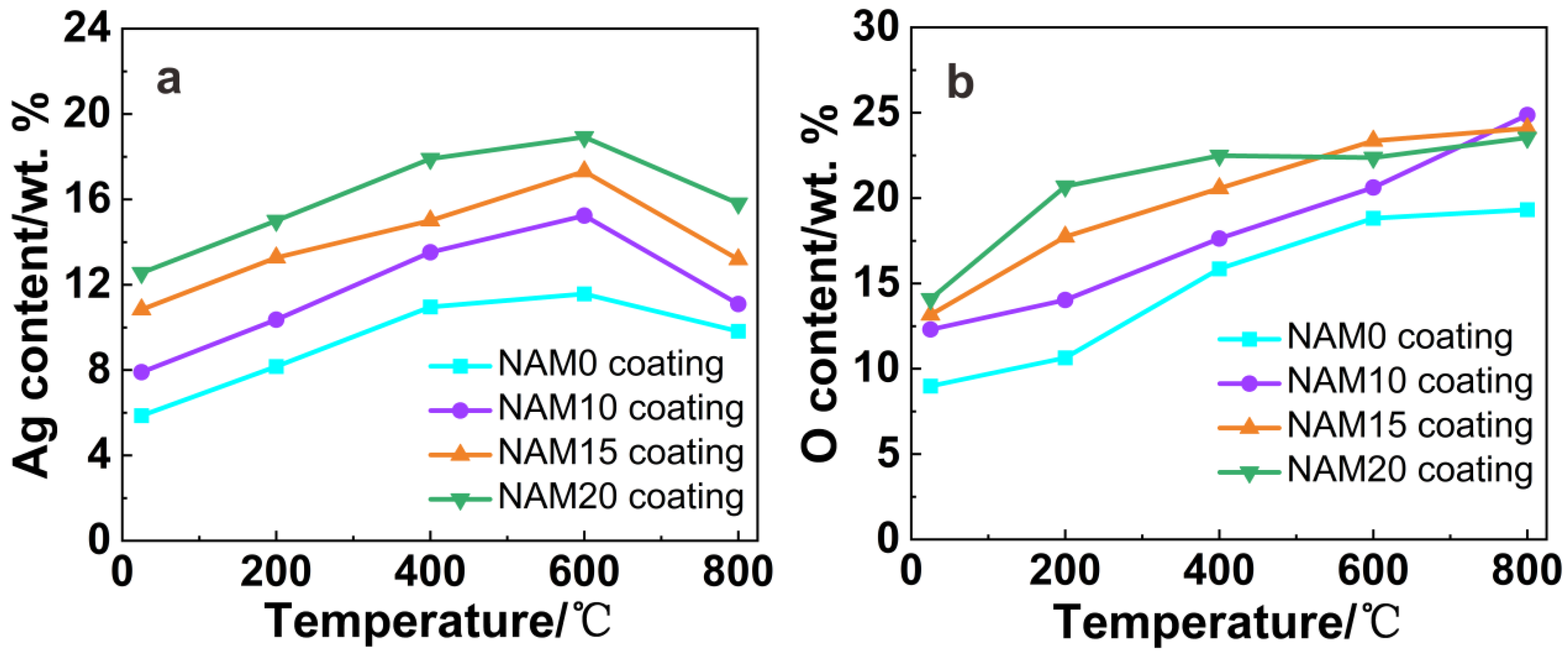
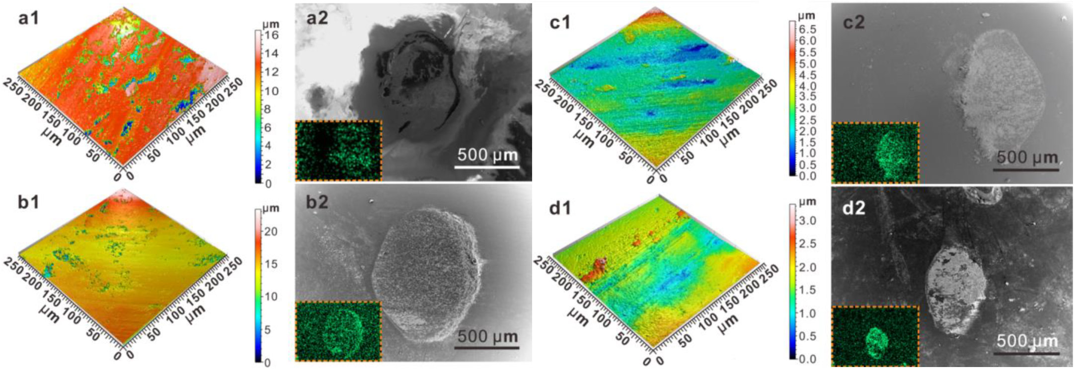
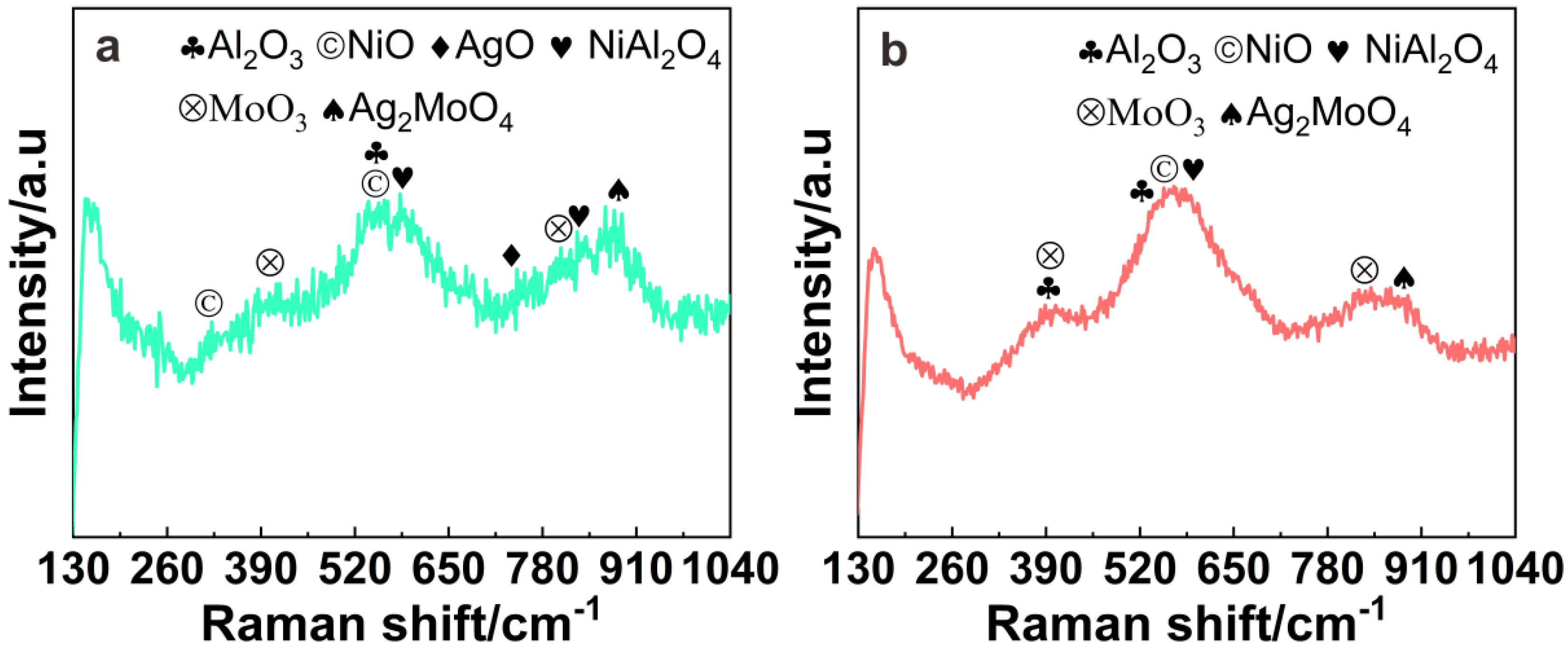
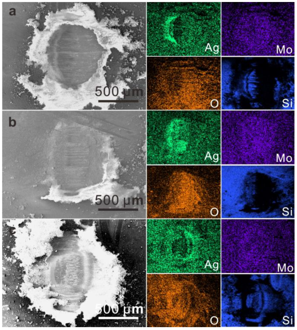
3.4. Worn Track Phase Composition

Figure 6 shows the Raman results of the worn tracks of NAM0 and NAM15 coatings from 25 °C to 800 °C. It can be seen that the two coatings show no prominent Raman peaks at 25 °C. At 200 °C and 400 °C, Al2O3 and NiO can be detected on the worn tracks of the two coatings, which results from the oxidation of Ni3Al. The results of Raman spectra are obviously different at 600 °C and 800 °C. The worn track mainly comprises NiO, Al2O3, AgO, and NiAl2O4 for the NAM0 coating, whereas the extra new Raman characteristic peaks at 890 cm−1 on the worn track of NAM15 coating can be found, which is in agreement with the Raman shift of Ag2MoO4 [17,18]. These imply that the Ag2MoO4 appears on the NAM15 worn track by a tri-chemical reaction from 600 °C.
Figure 7 gives the variations in the chemical states of Ag and Mo elements on the worn tracks of NAM15 coating at different temperatures detected by XPS technology. From Figure 7a, it is clear that the binding energy of the Ag element barely changed within 25–400 °C, indicating that the Ag 3d peaks on the worn tracks are mainly attributed to metallic Ag [19]. However, at 600 °C and 800 °C, the Ag 3d peaks on the worn tracks obviously shifted to lower binding energy compared with that at 25–400 °C. In order to determine the new phase generated, Figure 7b,c show the XPS results of Mo 3d peaks at 600 °C and 800 °C, respectively. According to Chen et al. [20] and Song et al. [21], the binding energies at 233.1 eV and 236.4 eV are assigned to MoO3, and the binding energies at 232.2 eV and 235.2 eV are assigned to Ag2MoO4. Thus, the results in Ag 3d and Mo 3d peaks suggest that the new high-temperature solid lubricant, Ag2MoO4, begins to form at 600 °C and higher temperatures, which is in good agreement with the Raman spectra results.

4. Discussion

4.1. Effect of MoO3 Additive on the Coating Microstructures and Mechanical Performances

It can be seen from Table 3 that the hardness of the formed NAM coatings decreases when the MoO3 content in the feedstock powder increases, which can be explained by two aspects. Firstly, the hardness of the MoO3 solid lubricant is much lower than that of the Ni3Al matrix phase. Secondly, the melting point (795 °C) and boiling point (1155 °C) of MoO3 are low, but the feedstock particles sprayed by a propane-fueled DJ-2700 gun are in the range of 1762 °C to 2065 °C [22,23,24]; in addition, the density of MoO3 is low, about 4.692 g/cm3. Thus, during the spraying process, part of the MoO3 volatilizes or cannot travel through the center of the flame [25,26]; therefore, the content of MoO3 deposited in the NAM coating is reduced, and high porosity in coatings formed. As can be demonstrated in Figure 1, the XRD diffraction peak intensity of MoO3 in the NAM15 coating is largely lower than that of the feedstock powder. Meanwhile, the porosity of NAM coatings increases with the increase in MoO3 content in the feedstock powder (Table 3). Consequently, the hardness of the coating is undoubtedly reduced. In addition, the decrease in the MoO3 content deposited in the NAM coating also decreases the deposition efficiency of the feedstock powders, resulting in a decrease in the thickness of the coating, as shown in Figure 2.
Similar to the changing trend of hardness, the adhesive bonding strength of the NAM coatings also decreased when the MoO3 content in the feedstock powder increase (Table 3). Because the adhesive bonding strength of the coating mainly depends on the bonding strength between the flat particles and the bonding strength between the coating and the substrate, the oxide particles reduce the surface area for deformation of the binder phase particles at the interface and between the coating and substrate, resulting in a decrease in the adhesive strength of the coating. The increase in the oxide phase reduces the bonding force between the oxide phase and the metal binder phase [27,28]. On the other hand, the melting points of Ni3Al and MoO3 are quite different, so the different powders are heated unevenly during the HVOF thermal spray process, which results in a low cohesive strength between the different phases. Therefore, the adhesive bonding strength of NAM coating decreases as the MoO3 content in the feedstock powder increases.

4.2. Effect of MoO3 Additive on the Coating Solid Lubricational Properties

At 25 °C, the COF of NAM coatings continually decrease with the increase in MoO3 content in the feedstock powder (as seen in Figure 3a). Interestingly, MoO3 is a high-temperature solid lubricant and has no lubrication capacity at low temperatures [9,10]. Figure 8 shows the EDS results of the worn tracks of the NAM coatings at various temperatures. At 25 °C, the content of the Ag element on the worn track significantly increases from 5.86 wt.% to 12.56 wt.% with the MoO3 content in the feedstock powder increasing to 20 wt.%. Combining the Raman and XPS results on the worn tracks (Figure 6 and Figure 7a), it can be confirmed that the Ag element on the worn track exists in a metallic state at 25–400 °C. As is known, the thermal expansion coefficient of metallic Ag is much higher than that of the Ni3Al matrix phase (Ni3Al, 1.2 × 10⁻⁵ K−1–1.6 × 10⁻⁵ K−1 (25–727 °C); Ag, 2.2 × 10⁻⁵ K−1 (25–900 °C)). During the frictional sliding process, metallic Ag with high plasticity and deformation ability can be partly extruded from the coating and then vertically migrates to the friction surface under the normal force and ambient temperature and plays an important role in reducing the COF [18,29]. It can be supposed that the pores and micro-cracks, which serve as the main channel for the precipitation of metallic Ag lubricant, have a direct effect on the content of metallic Ag migrating to the worn track. As in the result mentioned above, the porosity of the deposited NAM coatings increases with increasing of MoO3 content in the feedstock powder (Table 3), which may be responsible for the increase in the content of metallic Ag on the worn track (Figure 8). Therefore, as the MoO3 content increases in the feedstock powder from 0 wt.% to 20 wt.%, the brittle flaking on the worn track is significantly reduced, and the signs of friction are reduced (Figure 4a and Figure 5(a1–a3)). The above inference can also be confirmed from the 3D morphologies of the worn tracks and SEM morphologies and Ag distribution on the corresponding Si3N4 counterpart balls at 25 °C (Figure 9). From Figure 9(a1–d1), it can be observed that as the content of MoO3 in the feedstock powder increases, the worn track becomes much smoother, and the corresponding surface roughness (Sa) values are 2.03 μm, 1.32 μm, 0.53 μm, and 0.25 μm for NAM0, NAM10, NAM15, and NAM20 coatings, respectively. The surface roughness of the worn tracks has the same variation trend as the COF, which is consistent with the results of Xu et al. [30]. In addition, with the increase in MoO3 content in the feedstock powder, the distribution of Ag lubrication film on the corresponding Si3N4 counterpart ball becomes more continuous and compact (Figure 9(a2–d2)). It shows that the addition of MoO3 can promote the precipitation and transfer of Ag lubricant and the formation of Ag lubricating film, thereby effectively reducing the friction of the worn track (Figure 3a, Figure 4a, and Figure 5(a1–a3)).
When the temperature rises to 200 °C, the worn tracks of the NAM0, NAM10, and NAM15 coatings are much smoother than those at 25 °C because of the faster diffusion rate of metallic Ag at higher temperatures [8]. It can be seen from Figure 8 that the content of metallic Ag on the worn tracks significantly increases compared to those at 25 °C, thus further reducing the COF (Figure 3a). When the temperature increases to 400 °C, the COFs of NAM0, NAM10, and NAM15 coatings still decrease with the increase in temperature, and the main lubrication mechanism is the same as that at 25 °C and 200 °C (Figure 3a and Figure 8) [8]. It is worth noting that the COF of NAM15 coating is as low as 0.45 at this temperature. This could be explained as follows: on the one hand, the softening temperature of most oxides is about 0.4–0.7 times of their melting point, corresponding to the temperature at which the oxides transition from brittleness to plasticity [31]. The softening temperature of MoO3 (Tm: 795 °C) is about 318–557 °C, thus further decreasing the COF of the material in addition to the lubrication effect of metallic Ag. Secondly, the NAM15 coating has high mechanical properties and appropriate microstructure (Figure 2(c1,c2) and Table 1), which facilitates the formation of a smooth, continuous oxide lubrication film on its worn track. Thus, a relatively continuous and compact lubrication film containing Ag, MoO3, and NiO solid lubricants is generated on the worn track of NAM15 coating (Figure 5(b3), Figure 6 and Figure 7), which effectively reduces the shear force between the NAM15 coating and Si3N4 ceramic ball, thereby decreasing the COF (Figure 3a).
As the temperature rises to 600 °C and 800 °C, the COFs of NAM0, NAM10, and NAM15 coatings continuously decrease as the concentration of MoO3 in the feedstock powder increases. Especially, the COF of NAM15 coating sharply reduces to the lowest value of 0.41 and 0.36 when the test temperature was 600 °C and 800 °C, respectively (Figure 3a). This is because that Ag2MoO4 begins to form on the worn track at 600 °C (Figure 6b and Figure 7b). Ag2MoO4, which belongs to the three-dimensional triclinic system, is considered to be an excellent high-temperature solid lubricant due to the weak O-Ag-O bond in its layered structure being easily broken and responsible for the low shear strength of Ag2MoO4 at high temperature [32,33]. At 800 °C, the relative intensity of Ag2MoO4 on the worn track is significantly higher than that of the MoO3 (Figure 6b and Figure 7b,c), which indicates that more MoO3 is oxidized into Ag2MoO4 by the reaction of 4Ag + 2MoO3 + O2 = 2Ag2MoO4 [34]. When the reaction is carried out at 600 °C and 800 °C, the corresponding Gibbs free energies (ΔG) are −92.65 and −63.88 kJ/mol, respectively, indicating that this reaction can occur at those temperatures spontaneously. Meanwhile, the lubricants contained on the worn tracks are mainly NiO, Al2O3, and NiAl2O4 for NAM0 coating and NiO, Al2O3, NiAl2O4, MoO3, and Ag2MoO4 for NAM10 coating (Figure 6a and Figure 10a), the diverse lubricants produced on the worn tracks lead to differences in COFs. Erdemir [35,36] established a theoretical model of crystal chemistry using crystal chemistry methods by comparing and analyzing the correlation between the oxides’ ionic potential and their COFs and found that the COF of oxide is negatively correlated with its ionic potential. The lubricity of ternary oxides is related to the ionic potential difference between its binary oxides. The ionic potential of NiO, Al2O3, and MoO3 are 3.4, 6.5, and 8.9, and the ionic potential difference of NiAl2O4 and Ag2MoO4 are 3.1 and 7.4, respectively. This is consistent with our result of COF in Figure 3. It can also be seen from Figure 10b that the main components outside the worn track of NAM10 coating are mainly NiO, Al2O3, and NiAl2O4, which indicates that friction promotes the formation of the Ag2MoO4 high-temperature solid lubricant. The synergistic lubrication effect of the high-temperature lubricants such as NiO, Al2O3, and MoO3 and a large amount of Ag2MoO4 formed by high-temperature oxidation and tribo-chemical reaction results in the NAM15 coating possessing excellent anti-friction performance at 600 °C and 800 °C (Figure 3a).
As shown in Figure 3a, the COF of NAM20 coating increases continuously with increasing temperature, which is different from the trend of other coatings. Furthermore, the COFs of NAM15 and NAM20 coatings are both about 0.47 at 200 °C, indicating that the solid lubrication effect of Ag in NAM20 coating is restricted. As the concentration of MoO3 in the feedstock powder increases to 20 wt.%, the as-sprayed NAM20 coating has a large number of obvious pores and interlayer cracks (Figure 2(d1,d2)) which are prone to severe peeling during the sliding process at higher temperatures. The exfoliated hard-brittle MoO3 and Ni3Al particles would participate in the subsequent friction, resulting in aggravating abrasive wear and higher COF [37,38]. It can also be seen from Figure 5(b3) that the scratches on the worn track of NAM20 coating are significantly increased. Undoubtedly, this spalling phenomenon is more severe at higher temperatures, resulting in a constant increase in the COF (Figure 3a and Figure 5(c3–e3)).

4.3. Effect of MoO3 on the Wear-Resistant Properties of the NAM Coatings

At 25 °C, the WRs of all the NAM composite coatings are relatively low and increase when the MoO3 content in the feedstock powder increases. Compared with NAM0 coating, the WR of NAM10 and NAM15 coatings increases slightly while significantly increasing to 13.70 × 10⁻⁵ mm3/(Nm) as the MoO3 content in the feedstock powder increases to 20 wt.% (Figure 3b). This can be explained by the Archard wear equation, Q = (K × W × L)/H, in which Q is the wear volume, W is the load, H is the hardness of the coating, K is a constant, and L is the total sliding distance. Therefore, the WR is inversely proportional to the hardness [8]. At 200 °C, the NAM composite coatings were softened by the high temperature, and no continuous lubrication films were easily formed on the worn tracks (Figure 4b and Figure 5(b1–b3)). The coatings with lower hardness might fail to provide good bearing capacity, resulting in more heavy wear of the coating. As shown in Figure 3b, the WR trend of NAM coating with increasing MoO3 content in the feedstock powder is the same as that at 25 °C, and at the same time, the WRs of the NAM coatings are all higher than 25 °C (Figure 3b).
At 400 °C, the WR of NAM0 coating further increased due to the weakening of coating mechanical properties, and the coating is depicted by damaged pieces and a larger amount of wear debris (Figure 4c). While the WR of the NAM10 and NAM15 coatings is significantly reduced, it indicates that the incorporation of a certain amount of MoO3 is beneficial to the enhancement of the wear resistance of the coatings at moderate temperature. As shown in Figure 5(c1,c2), a thin lubrication film rich in Ag, NiO, and MoO3 would be found on the worn track of NAM10 and NAM15 coatings (Figure 6 and Figure 7), and the lubrication film becomes more complete with the increase in MoO3 amount in the feedstock powder due to the precipitation of Ag and brittle-plastic transition of MoO3 (Figure 8). Numerous researchers have found that the lubrication film generated at a high temperature can effectively reduce the direct contact between the coating and Si3N4 ceramic ball surfaces and improve the wear resistance of the coating [7,39]. Therefore, the NAM15 coating, with optimum microstructure, presents the best wear resistance performance due to the continuous and complete lubrication film that formed. As the temperature further increases to 600 °C and 800 °C, the O content on the worn tracks of all coatings is further increased (Figure 8), and the oxidation is intensified. A thicker and compacted oxide film is distributed on the worn tracks of all the coatings (Figure 4d,e and Figure 5(d1,e1),(d2,e2),(d3,e3)), which further improves the wear resistance of the coatings (Figure 3b). The worn track of the NAM15 coating, especially, forms a continuous and complete lubrication film without obvious defects. Figure 11a,b give the SEM morphologies and elemental distribution mappings of the Si3N4 counterpart balls against NAM10 and NAM15 coatings at 800 °C, respectively. It is observed that a continuous, smooth, and completed transfer film which is rich in Ag, Ni, Mo, and O has formed on the worn scar of the Si3N4 ball against NAM15 coating, in which the composition is similar to that of the lubrication film formed on the NAM15 coating (Figure 6b and Figure 7). This is because the lubrication film on the worn track is transferred to the surface of the Si3N4 ceramic ball to form a transfer film under the action of shear force and effectively prevents the direct contact between the rubbing surfaces [40]. The grooves on the worn track of NAM15 coating are shallower, and the Si content on the worn track of NAM15 coating is the lowest, and the wear debris formed during the friction process is mainly fine particles with the size of 31 μm × 31 μm (Figure 12), smaller than that of the size of 62 μm × 83 μm formed in the NAM10 coating system is. For NAM20 coating, the obvious splat delamination appears on the worn track (Figure 5(c3–e3)), attributed to the fact that the addition of a large amount of MoO3 in the feedstock powder results in obvious interlayer cracks in the deposited coating (Figure 2(d1,d2)). The friction process promotes the propagation of the interlayer cracks, which eventually leads to splat delamination [41]. As shown in Figure 12c, the wear debris produced in the NAM20 coating system is mainly in the form of flakes with a large size of 83 μm × 175 μm. A large number of large-sized wear debris participates in the subsequent friction process, causing the lubricating film to be ruptured and the transfer film to fall off (Figure 5(e3) and Figure 11c). Instead, excessive MoO3 lubricant additive in the feedstock powder deteriorates the tribological behaviors of the deposited coating at higher temperatures (Figure 3).

5. Conclusions

In this work, the Ni3Al-based composite coatings were deposited by HVOF spraying technology by tailoring the content of MoO3 in the feedstock powder, and the effects of MoO3 on the microstructure, mechanical, and tribological properties at the range of 25 °C to 800 °C were studied. The main conclusions that can be drawn are as follows:
(1)
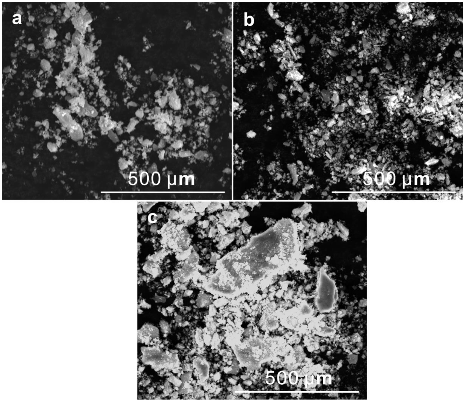
An appropriate amount of MoO3 in the feedstock powder has little effect on the microstructure and mechanical properties of the deposited Ni3Al-based composite coating, and the HVOF sprayed NAM coatings have a high-level adhesive bonding strength of more than 45 MPa. When the MoO3 content in the feedstock powder reaches 20 wt.%, the microstructure and mechanical properties of the deposited coating deteriorate sharply.
(2)
The NAM composite coating formed by feedstock powder containing 15 wt.% MoO3 additive presents more excellent tribological performance with COF of 0.63–0.36 in the range of 25 °C to 800 °C and WR of 25.11–6.03 × 10⁻⁵ mm3/(Nm) in the range of 400 °C to 800 °C.
(3)
In the temperature range of 25 °C to 400 °C, the effective lubricant of the coating was mainly metallic Ag; MoO3 occurs in brittle-plastic transitions and exhibits lubrication properties above 318 °C, and the addition of 15 wt.% MoO3 in the feedstock powder minimizes the deposited NAM coating abrasive wear. At 600 °C to 800 °C, the synergistic lubrication effect of the high-temperature solid lubricants such as NiO, Al2O3, MoO3 and a large amount of Ag2MoO4 formed by high-temperature oxidation and tribo-chemical reaction results in an excellent anti-friction performance of the NAM15 coating.
(4)
An excessive amount of MoO3 in the feedstock powder (20 wt.%) results in inferior interlayer bonding of the deposited coating, and the NAM20 coating is more prone to delamination, leading to a deterioration of the tribological performance and aggravation of delamination wear and abrasive wear at higher temperatures from 200 °C to 800 °C.

Author Contributions

Conceptualization, B.C. and H.Z.; methodology, S.C., B.C. and H.Z.; software, S.Z.; validation, S.Z. and X.F.; formal analysis, J.Y. and S.Z.; investigation, X.F.; resources, W.L.; data curation, X.F.; writing—original draft preparation, X.F.; writing—review and editing, W.L.; visualization, J.Y. and S.Z.; supervision, W.L.; project administration, W.L.; funding acquisition, W.L. All authors have read and agreed to the published version of the manuscript.

Funding

The research was funded by the National Natural Science Foundation of China [52075234, 51674130], the National Key Research and Development Program [2022YFE0121900], the Major Basic Research Project of Shandong [ZR2022ZD13], the Major Project of Science and Technology of Gansu [21ZD4DA017], and the “111” project [D21032].

Institutional Review Board Statement

Not applicable.

Informed Consent Statement

Not applicable.

Data Availability Statement

Not applicable.

Conflicts of Interest

The authors declare no conflict of interest.

References

  1. Hanyaloglu, S.C.; Aksakal, B.; Mccolm, I.J. Reactive sintering of electroless nickel-plated aluminum powders. Mater. Charact. 2001, 47, 9–16. [Google Scholar] [CrossRef]
  2. Lu, L.; Lai, M.O.; Zhang, S. Evolution and characterization of a Ni3Al intermetallic compound during mechanical alloying. Mater. Des. 1994, 15, 79–86. [Google Scholar] [CrossRef]
  3. Huang, B.; Xiong, W.H.; Yang, Q.Q.; Yao, Z.H.; Zhang, G.P.; Zhang, M. Preparation, microstructure and mechanical properties of multicomponent Ni3Al-bonded cermets. Ceram. Int. 2014, 40, 14073–14081. [Google Scholar] [CrossRef]
  4. Yan, Z.; Shi, X.L.; Huang, Y.C.; Deng, X.B.; Yang, K.; Liu, X.Y. Tribological performance of Ni3Al matrix self-lubricating composites containing multilayer graphene and Ti3SiC2 at elevated temperatures. J. Mater. Eng. Perform. 2017, 26, 4605–4614. [Google Scholar] [CrossRef]
  5. Zhai, W.Z.; Shi, X.L.; Wang, M.; Xu, Z.S.; Yao, J.; Song, S.Y.; Wang, Y.F. Grain refinement: A mechanism for graphene nanoplatelets to reduce friction and wear of Ni3Al matrix self-lubricating composites. Wear 2014, 310, 33–40. [Google Scholar] [CrossRef]
  6. Zhu, S.Y.; Bi, Q.L.; Yang, J.; Liu, W.M. Tribological property of Ni3Al matrix composites with addition of BaMoO4. Tribol. Lett. 2011, 43, 55–63. [Google Scholar] [CrossRef]
  7. Stone, D.; Liu, J.; Singh, D.P.; Muratore, C.; Voevodin, A.A.; Mishra, S.; Rebholz, C.; Ge, Q.; Aouadi, S.M. Layered atomic structures of double oxides for low shear strength at high temperatures. Scripta Mater. 2010, 62, 735–738. [Google Scholar] [CrossRef]
  8. Chen, J.; An, Y.L.; Yang, J.; Zhao, X.Q.; Yan, F.Y.; Zhou, H.D.; Chen, J.M. Tribological properties of adaptive NiCrAlY-Ag-Mo coatings prepared by atmospheric plasma spraying. Surf. Coat. Tech. 2013, 235, 521–528. [Google Scholar] [CrossRef]
  9. Sliney, H.E. Solid lubricant materials for high temperatures: A review. Tribol. Int. 1982, 15, 303–315. [Google Scholar] [CrossRef] [Green Version]
  10. Zhu, S.Y.; Li, F.; Ma, J.Q.; Cheng, J.; Yin, B.; Yang, J.; Qiao, Z.H.; Liu, W.M. Tribological properties of Ni3Al matrix composites with addition of silver and barium salt. Tribol. Int. 2015, 84, 118–123. [Google Scholar] [CrossRef]
  11. Tyagi, R.; Xiong, D.S.; Li, J.L.; Dai, J.H. Elevated temperature tribological behavior of Ni based composites containing nano-silver and hBN. Wear 2010, 269, 884–890. [Google Scholar] [CrossRef]
  12. Shi, X.L.; Song, S.Y.; Zhai, W.Z.; Wang, M.; Xu, Z.S.; Yao, J.; Zhang, Q.X. Tribological behavior of Ni3Al matrix self-lubricating composites containing WS2, Ag and hBN tested from room temperature to 800 °C. Mater. Des. 2014, 55, 75–84. [Google Scholar] [CrossRef]
  13. Wang, J.Y.; Shan, Y.; Guo, H.J.; Li, B.; Wang, W.Z.; Jia, J.H. Friction and wear characteristics of hot-pressed NiCr-Mo/MoO3/Ag self-lubrication composites at elevated temperatures up to 900 °C. Tribol. Lett. 2015, 59, 48. [Google Scholar] [CrossRef]
  14. Fan, X.J.; Li, W.S.; Yang, J.; Cui, S.; Zhai, H.M.; He, D.Q.; Cheng, B.; Liu, W.M. Optimization of the HVOF spray deposition of Ni3Al coatings on stainless steel. J. Therm. Spray Tech. 2022, 31, 1598–1608. [Google Scholar] [CrossRef]
  15. Shen, Q.; Shi, X.L.; Yang, K.; Zou, J.L.; Zhai, W.Z.; Huang, Y.C. Tribological performance of TiAl matrix composites containing silver and V2O5 nanowires at elevated temperatures. RSC Adv. 2016, 6, 56294–56302. [Google Scholar] [CrossRef]
  16. Yang, Y.; Zhang, C.; Peng, Y.; Yu, Y.; Liu, L. Effects of crystallization on the corrosion resistance of Fe-based amorphous coatings. Corros. Sci. 2012, 9, 10–19. [Google Scholar] [CrossRef]
  17. Li, B.; Gao, Y.M.; Han, M.M.; Guo, H.J.; Jia, J.H.; Wang, W.Z.; Deng, H. Tribological properties of NiAl matrix composite coatings synthesized by plasma spraying method. J. Mater. Res. 2017, 32, 1674–1681. [Google Scholar] [CrossRef]
  18. Ouyang, J.H.; Sasaki, S.; Murakami, T.; Umeda, K. Tribological properties of spark-plasma-sintered ZrO2(Y2O3)-CaF2-Ag composites at elevated temperatures. Wear 2005, 258, 1444–1454. [Google Scholar] [CrossRef]
  19. Liu, E.Y.; Gao, Y.M.; Wang, W.Z.; Zhang, X.L.; Wang, X.; Yi, G.W.; Jia, J.H. Effect of Ag2Mo2O7 incorporation on the tribological characteristics of adaptive Ni-based composite at elevated temperatures. Tribol. T. 2013, 56, 469–479. [Google Scholar] [CrossRef]
  20. Chen, F.Y.; Feng, Y.; Shao, H.; Zhang, X.B.; Chen, J.; Chen, N.N. Friction and wear behaviors of Ag/MoS2/G composite in different atmospheres and at different temperatures. Tribol. T. 2012, 47, 139–148. [Google Scholar] [CrossRef]
  21. Song, Y.Y.; Xie, W.Y.; Yang, C.; Wei, D.D.; Su, X.T.; Li, L.; Wang, L.; Wang, J.D. Humic acid-assisted synthesis of Ag/Ag2MoO4 and Ag/Ag2WO4 and their highly catalytic reduction of nitro-and azo-aromatics. J. Mater. Res. Technol. 2020, 9, 5774–5783. [Google Scholar] [CrossRef]
  22. Ding, X.; Cheng, X.D.; Shi, J.; Li, C.; Yuan, C.Q.; Ding, Z.X. Influence of WC size and HVOF process on erosion wear performance of WC-10Co4Cr coatings. Int. J. Adv. Manuf. Tech. 2018, 96, 1615–1624. [Google Scholar] [CrossRef]
  23. Hermann-Muñoz, J.A.; Rincón-López, J.A.; Clavijo-Mejía, G.A.; Giraldo-Betancur, A.L.; Alvarado-Orozco, J.M.; Vizcaya-Ruiz, A.; Muñoz-Saldaña, J. Influence of HVOF parameters on HAp coating generation: An integrated approach using process maps. Surf. Coat. Tech. 2019, 358, 299–307. [Google Scholar] [CrossRef] [Green Version]
  24. Ludwig, G.A.; Malfatti, C.F.; Schroeder, R.M.; Ferrari, V.Z.; Muller, I.L. WC10Co4Cr coatings deposited by HVOF on martensitic stainless steel for use in hydraulic turbines: Resistance to corrosion and slurry erosion. Surf. Coat. Tech. 2019, 377, 124918. [Google Scholar] [CrossRef]
  25. Omid, T.; Mohammad, H.G.; Hamid, T.; Hamid, T. A study on mechanochemical behavior of MoO3-Mg-C to synthesize molybdenum carbide. Int. J. Refract Met. H. 2014, 47, 18–24. [Google Scholar]
  26. Shi, P.Y.; Yi, G.W.; Wan, S.H.; Sun, H.W.; Feng, X.C.; Pham, S.T.; Xie, E.Q.; Wang, Q.H. High temperature tribological performance of nickel-based composite coatings by incorporating multiple oxides (TiO2-ZnO-MoO3). Tribol. Int. 2020, 155, 106759. [Google Scholar] [CrossRef]
  27. Guo, T.; Chen, Y.M.; Cao, R.H.; Pang, X.L.; He, J.Y.; Qiao, L.J. Cleavage cracking of ductile-metal substrates induced by brittle coating fracture. Acta Mater. 2018, 152, 77–85. [Google Scholar] [CrossRef]
  28. Li, G.R.; Yang, G.J.; Li, C.X.; Li, C.J. Force transmission and its effect on structural changes in plasma-sprayed lamellar ceramic coatings. J. Eur. Ceram. Soc. 2017, 37, 2877–2888. [Google Scholar] [CrossRef]
  29. Liu, F.; Jia, J.H. Tribological properties and wear mechanisms of NiCr-Al2O3-SrSO4-Ag self-lubricating composites at elevated temperatures. Tribol. Lett. 2013, 49, 281–290. [Google Scholar] [CrossRef]
  30. Xu, Z.S.; Zhang, Q.X.; Zhai, W.Z. Wear and friction behaviour of TiAl matrix self-lubricating composites filled with WS2, MoO3 or multilayer graphene. RSC Adv. 2015, 5, 93554–93562. [Google Scholar] [CrossRef]
  31. Gulbiński, W.; Suszko, T. Thin films of Mo2N/Ag nanocomposite-the structure, mechanical and tribological properties. Surf. Coat. Tech. 2006, 201, 1469–1476. [Google Scholar] [CrossRef]
  32. Torres, H.; Ripoll, M.R.; Prakash, B. Tribological behaviour of self-lubricating materials at high temperatures. Int. Mater. Rev. 2017, 63, 309–340. [Google Scholar] [CrossRef]
  33. Aouadi, S.M.; Paudel, Y.; Simonson, W.J.; Ge, Q.; Kohli, P.; Muratore, C.; Voevodin, A.A. Tribological investigation of adaptive Mo2N/MoS2/Ag coatings with high sulfur content. Surf. Coat. Tech. 2009, 203, 1304–1309. [Google Scholar] [CrossRef]
  34. Liu, E.Y.; Wang, W.Z.; Gao, Y.M.; Jia, J.H. Tribological properties of Ni-based self-lubricating composites with addition of silver and molybdenum disulfide. Tribol. Int. 2013, 57, 235–241. [Google Scholar] [CrossRef]
  35. Erdemir, A. A crystal-chemical approach to lubrication by solid oxides. Tribol. Lett. 2000, 8, 97–102. [Google Scholar] [CrossRef]
  36. Erdemir, A. A crystal chemical approach to the formulation of self-lubricating nanocomposite coatings. Surf. Coat. Tech. 2005, 200, 1792–1796. [Google Scholar] [CrossRef]
  37. Kong, L.Q.; Zhu, S.Y.; Qiao, Z.H.; Yang, J.; Bi, Q.L.; Liu, W.M. Effect of Mo and Ag on the friction and wear behavior of ZrO2(Y2O3)-Ag-CaF2-Mo composites from 20 °C to 1000 °C. Tribol. Int. 2014, 78, 7–13. [Google Scholar] [CrossRef]
  38. Yu, Y.J.; Zhou, J.S.; Ren, S.F.; Wang, L.Q.; Xin, B.B.; Cao, S.L. Tribological properties of laser cladding NiAl intermetallic compound coatings at elevated temperatures. Tribol. Int. 2016, 104, 321–327. [Google Scholar] [CrossRef]
  39. Blau, P.J. Elevated-temperature tribology of metallic materials. Tribol. Int. 2010, 43, 1203–1208. [Google Scholar] [CrossRef]
  40. Franklin, S.E.; Kraker, A.D. Investigation of counterface surface topography effects on the wear and transfer behavior of a POM-20 % PTFE composite. Wear 2003, 255, 766–773. [Google Scholar] [CrossRef]
  41. Guilemany, J.M.; Miguel, J.M.; Armada, S.; Vizcaino, S.; Climent, F. Use of scanning white light interferometry in the characterization of wear mechanisms in thermal-sprayed coatings. Mater. Charact. 2001, 47, 307–331. [Google Scholar] [CrossRef]
Figure 1. XRD results of the NAM15 feedstock powder (a) and corresponding as-sprayed NAM15 coating (b).
Coatings 13 00624 g001
Figure 2. The polished surface and sectional SEM morphologies of (a1,a2) NAM0, (b1,b2) NAM10, (c1,c2) NAM15, and(d1,d2) NAM20 coatings. (c2′) Local magnified morphology of (c2) and corresponding EDS elemental distributions.
Coatings 13 00624 g002
Figure 3. COFs (a) and WRs (b) of the NAM coatings at various temperatures.
Coatings 13 00624 g003
Figure 4. SEM images of the worn tracks of NAM0 composite coating: (a) 25 °C, (b) 200 °C, (c) 400 °C, (d) 600 °C, (e) 800 °C.
Coatings 13 00624 g004
Figure 5. SEM images of the worn tracks: (a1e1) NAM10 coating, (a2e2) NAM15 coating, (a3e3) and NAM20 coating. (a1a3) 25 °C, (b1b3) 200 °C, (c1c3) 400 °C, (d1d3) 600 °C, (e1e3) 800 °C.
Coatings 13 00624 g005
Figure 6. Raman results of the worn tracks of NAM0 and NAM15 coatings at various temperatures: (a) NAM0 coating and (b) NAM15 coating.
Coatings 13 00624 g006
Figure 7. XPS spectra of the worn tracks of NAM15 coating: (a) Ag at various temperatures, (b) Mo at 600 °C, (c) Mo at 800 °C.
Coatings 13 00624 g007
Figure 8. EDS results of the worn tracks (Figure 4 and Figure 5) at various temperatures: (a) Ag content and (b) O content.
Coatings 13 00624 g008
Figure 9. Three-dimensional images of the worn tracks, SEM images, and Ag distribution on the corresponding Si3N4 counterpart balls corresponding to the coatings at 25 °C: (a1,a2) NAM0 coating, (b1,b2) NAM10 coating, (c1,c2) NAM15 coating, (d1,d2) NAM20 coating.
Coatings 13 00624 g009
Figure 10. Raman results of the NAM10 coating tested at 800 °C: (a) within the worn track and (b) outside the worn track.
Coatings 13 00624 g010
Figure 11. SEM morphologies and elemental distribution of the Si3N4 counterpart balls against (a) NAM10 coating, (b) NAM15 coating, and (c) NAM20 coating at 800 °C.
Coatings 13 00624 g011
Figure 12. SEM morphologies of the wear debris at 800 °C: (a) NAM10 coating, (b) NAM15 coating, (c) NAM20 coating.
Coatings 13 00624 g012
Table 1. Compositions of the NAM feedstock powder.
Feedstock PowderCompositions (wt.%)
Ni3AlAgMoO3
NAM09010-
NAM10801010
NAM15751015
NAM20701020
Table 2. The optimized HVOF spray parameters.
ParameterValue
Oxygen flow (L/s)4.53
Propane gas flow (L/s)1.19
Compressed air flow (L/s)6.25
Nitrogen carrier gas flow (L/s)0.21
Powder feed rate (g/s)0.83
Gun speed (mm/s)300
Spray distance (mm)250
Table 3. Mechanical properties of the polished NAM coating.
Composite CoatingVickers Hardness (HV)Adhesive Bonding Strength (MPa)Coating Porosity (Vol. %)
NAM0486.0 ± 9.159.4 ± 5.42.06
NAM10466.9 ± 12.256.6 ± 2.72.71
NAM15449.1 ± 14.753.1 ± 1.53.59
NAM20356.8 ± 17.947.5 ± 4.85.53
Disclaimer/Publisher’s Note: The statements, opinions and data contained in all publications are solely those of the individual author(s) and contributor(s) and not of MDPI and/or the editor(s). MDPI and/or the editor(s) disclaim responsibility for any injury to people or property resulting from any ideas, methods, instructions or products referred to in the content.

