
Antifouling Coatings Fabricated by Laser Cladding

Abstract
:1. Introduction
2. Experiment
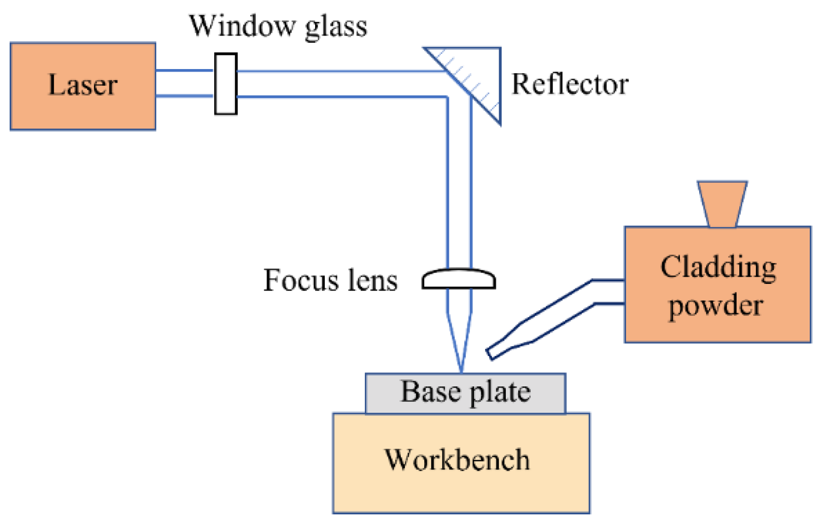
2.1. Preparation of Antifouling Coatings
2.2. Experimental Methodology
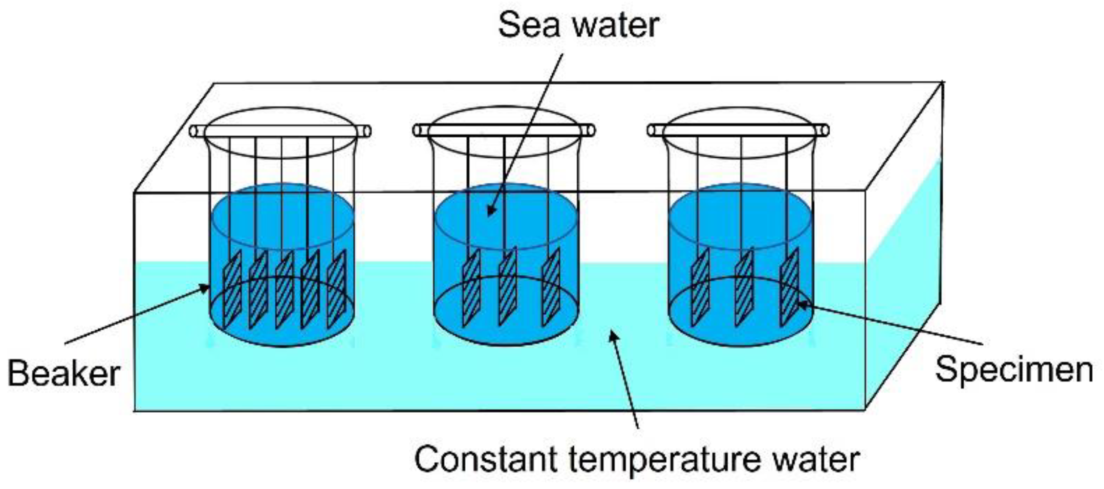
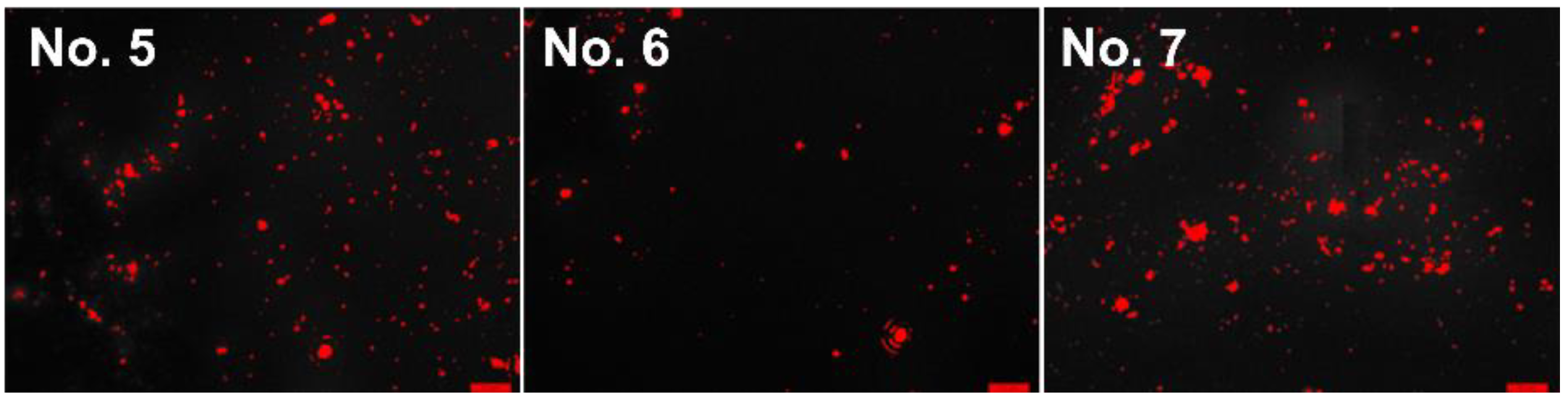
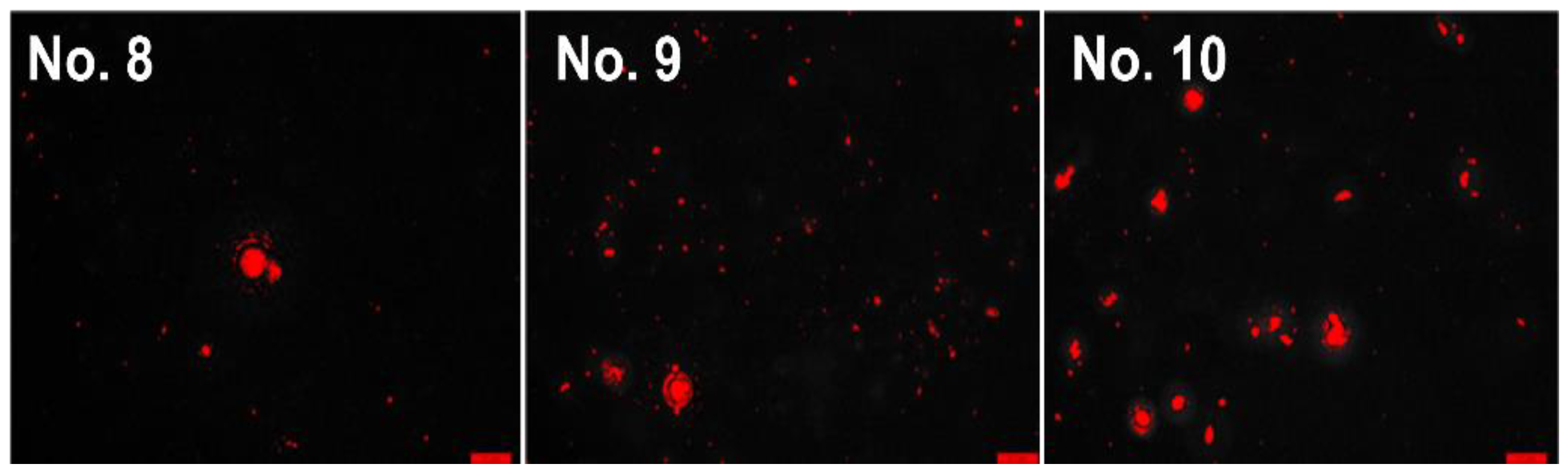
2.2.1. The Microbial Attachment Testing
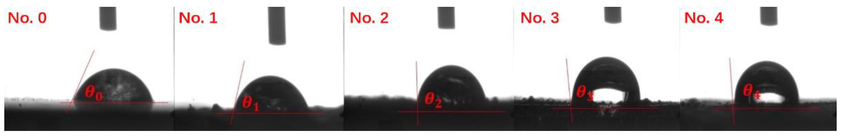
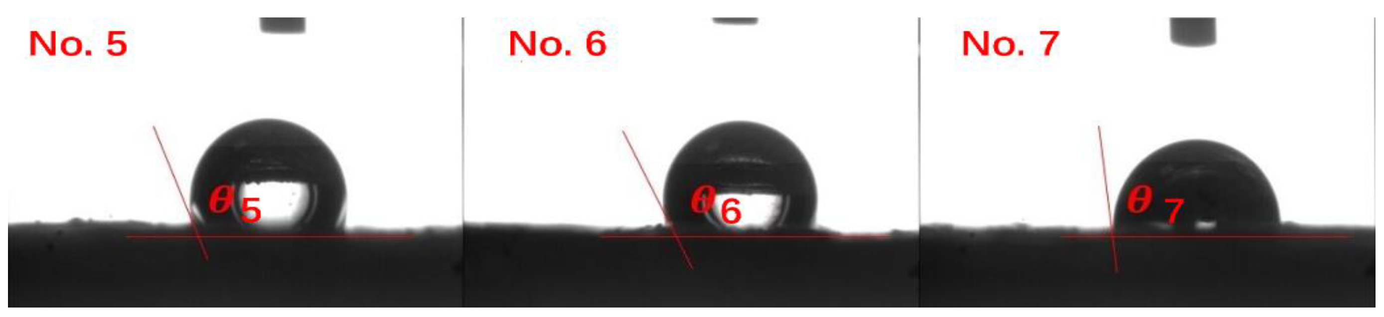
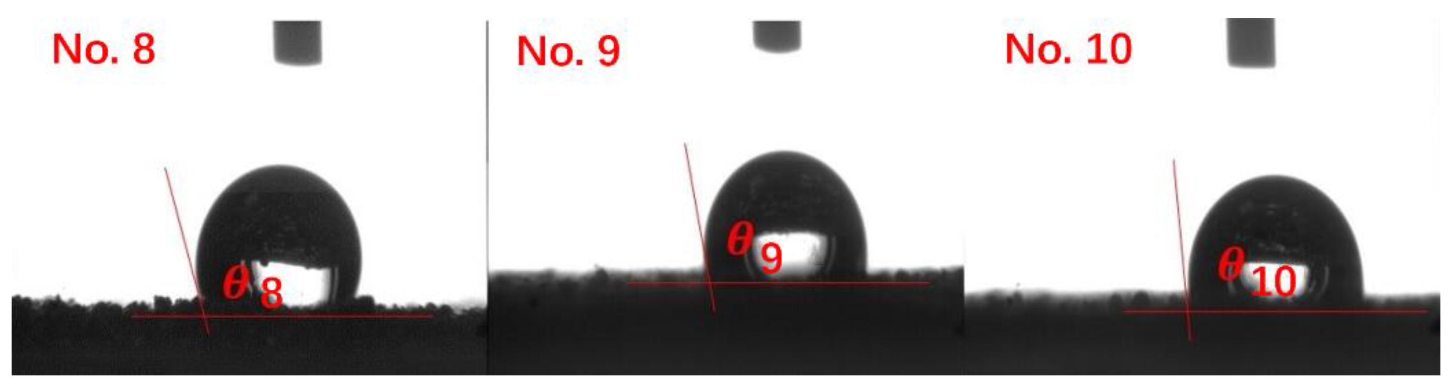
2.2.2. The Wettability Testing
2.2.3. The Mechanism of Antifouling Surface
3. Results and Discussion
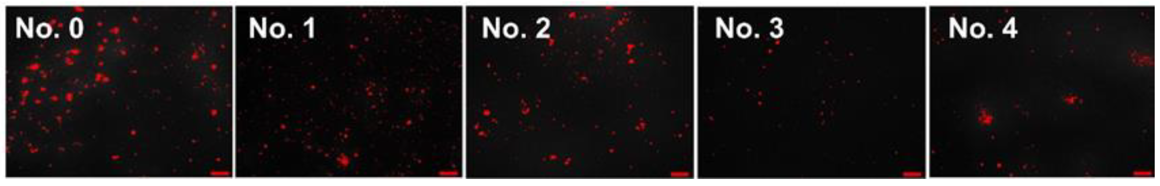
3.1. The Antifouling Performance of LCCs
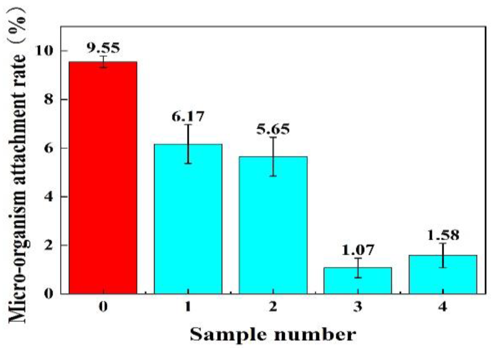
3.1.1. Effect of Ni60/TC4 Mass Ratio
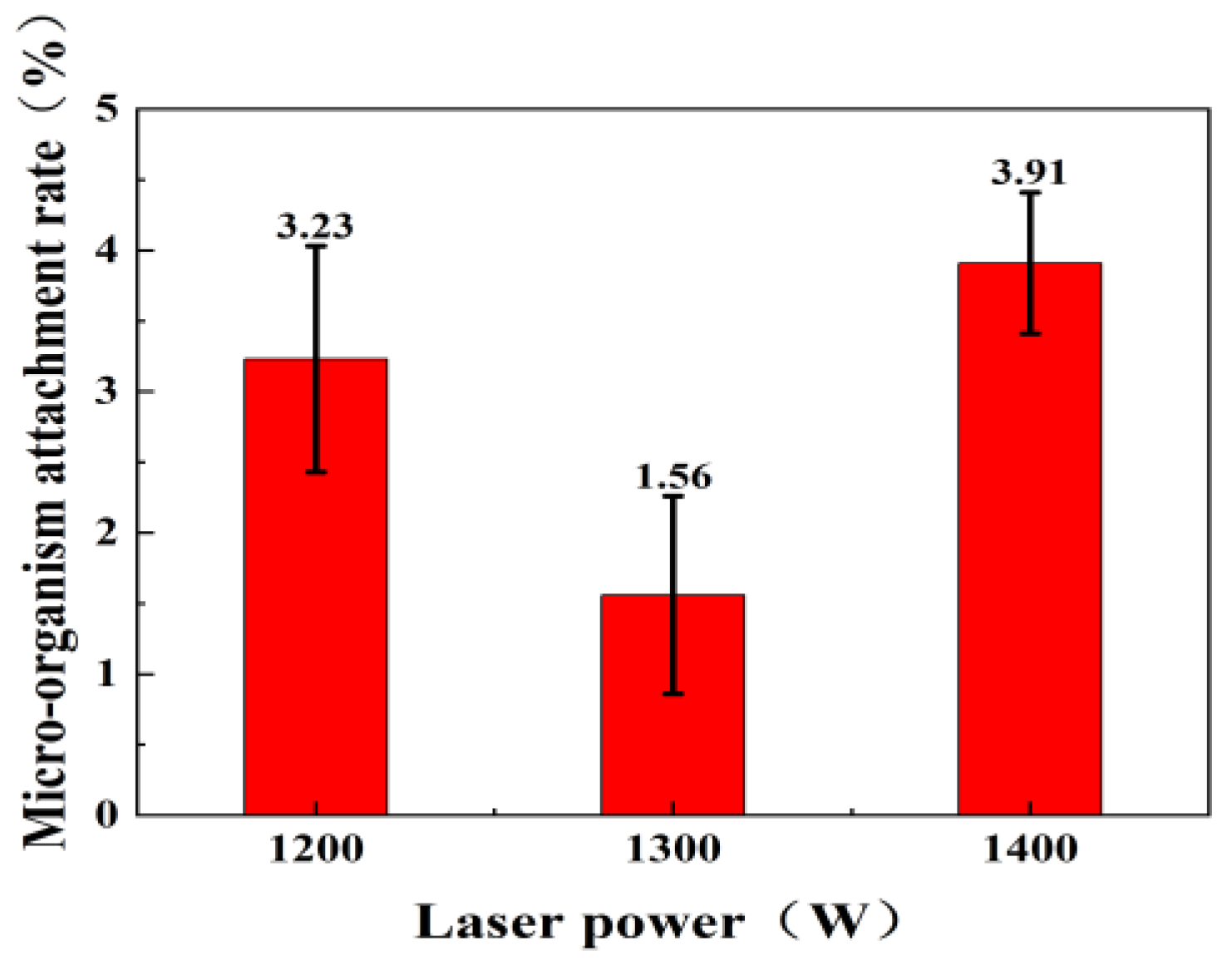
3.1.2. Effect of Laser Cladding Power
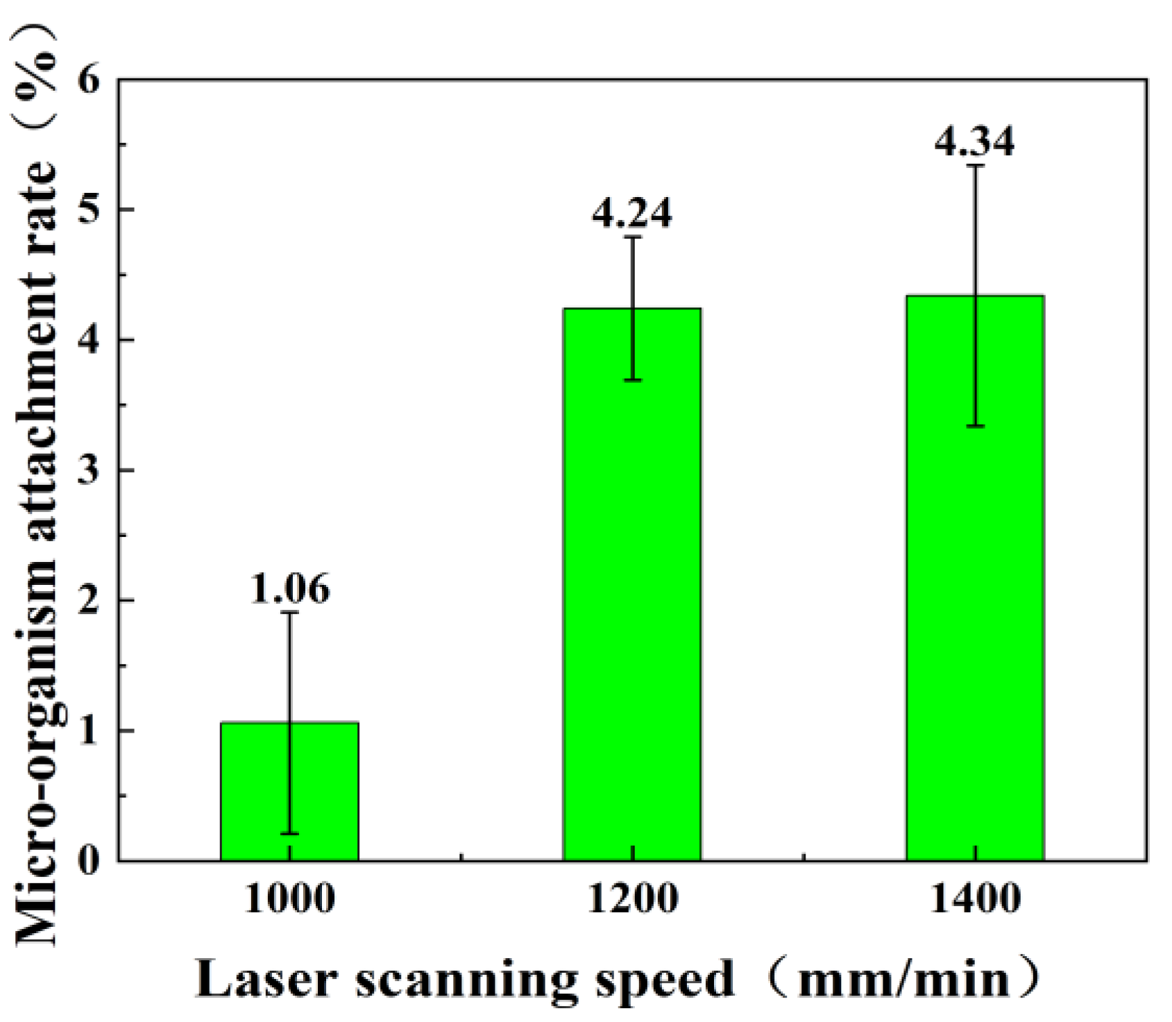
3.1.3. Effect of Laser Scanning Speed
3.2. Wettability of LCCs
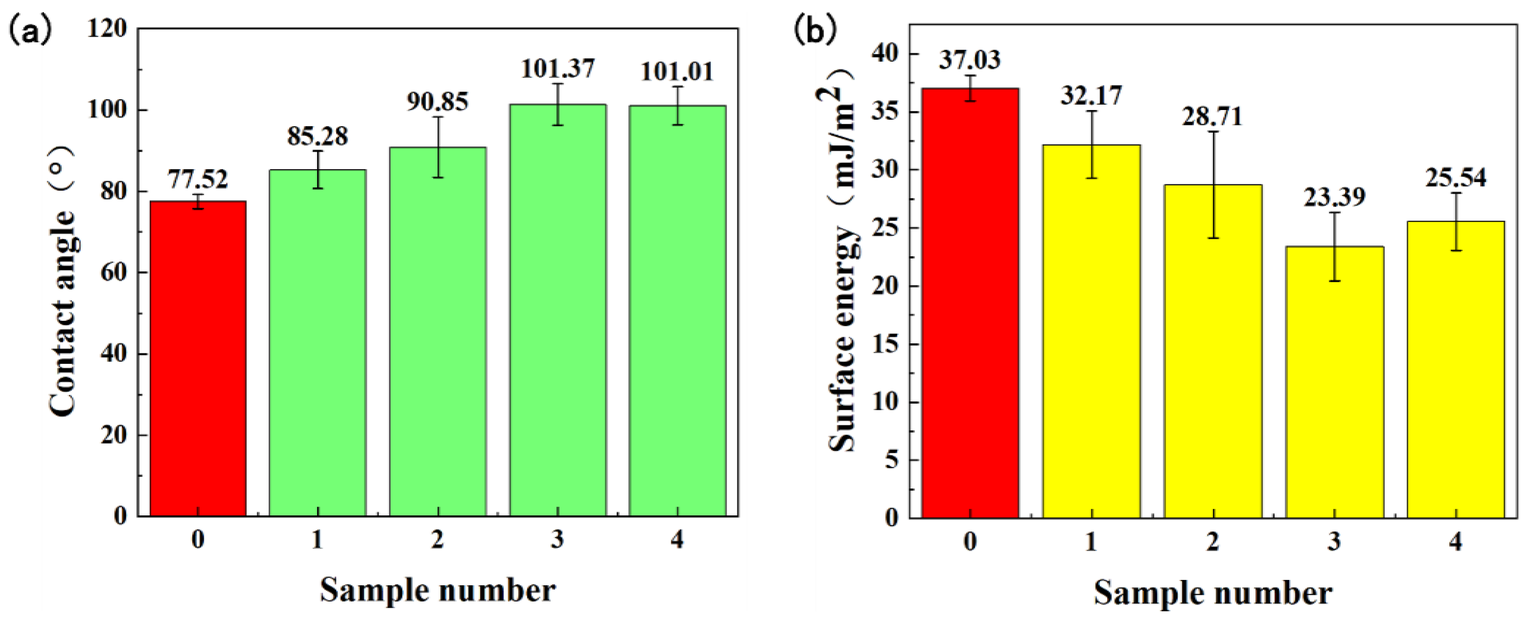
3.2.1. Effect of Ni60/TC4 Mass Ratio
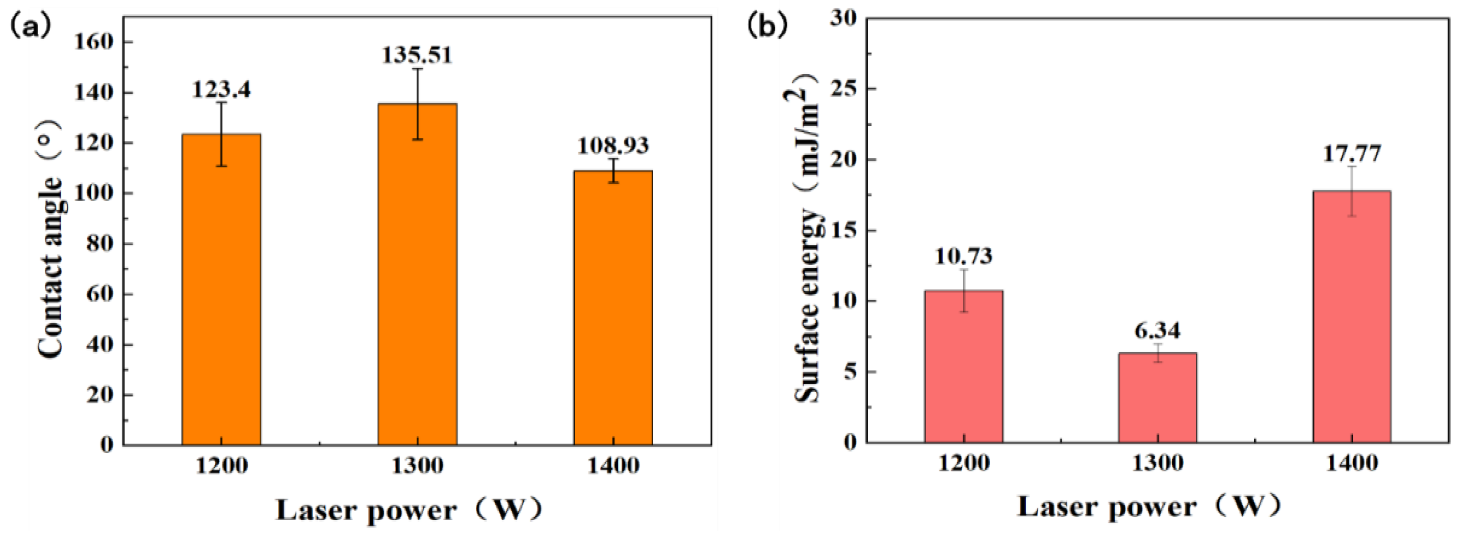
3.2.2. Effect of Laser Cladding Power
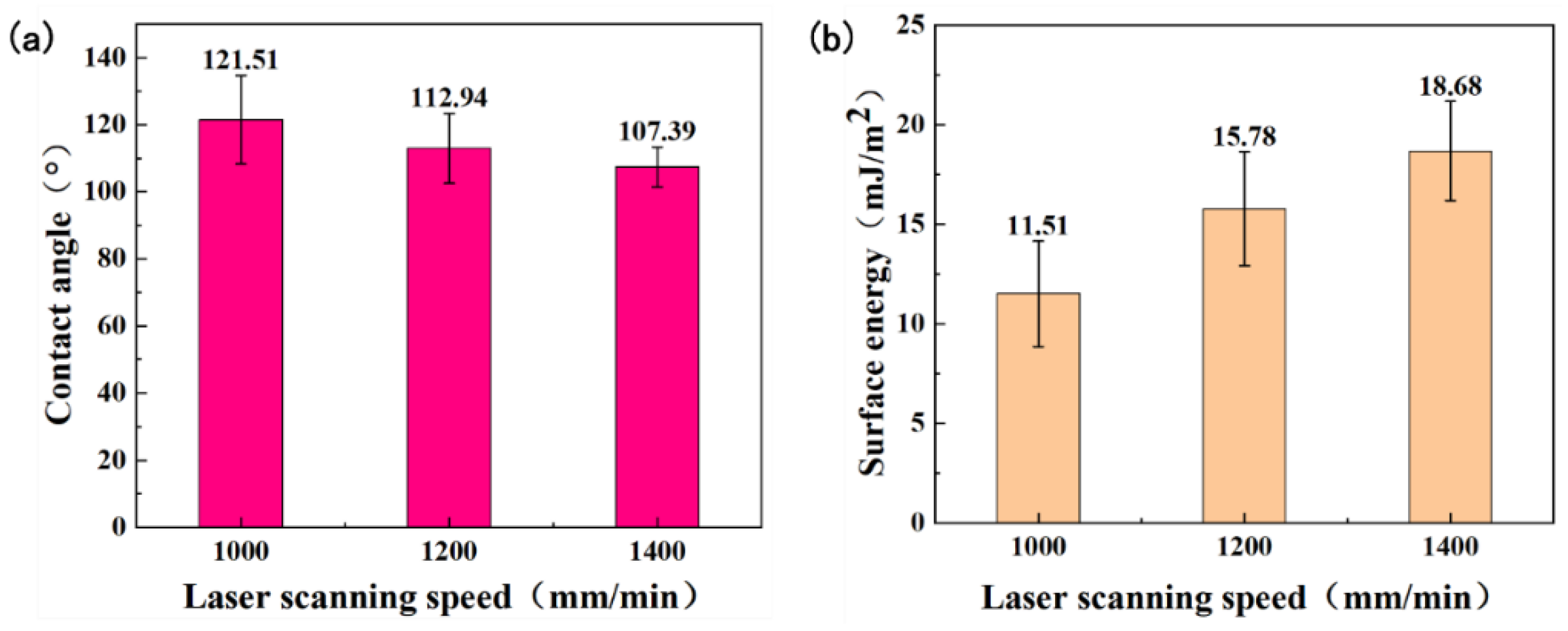
3.2.3. Effect of Laser Scanning Speed
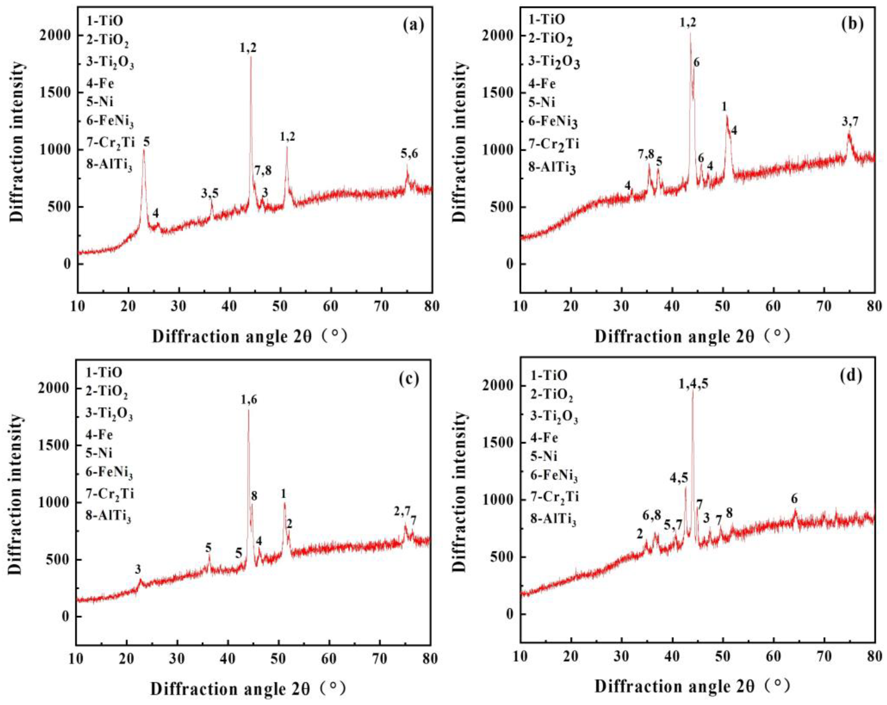
3.3. Phase Composition
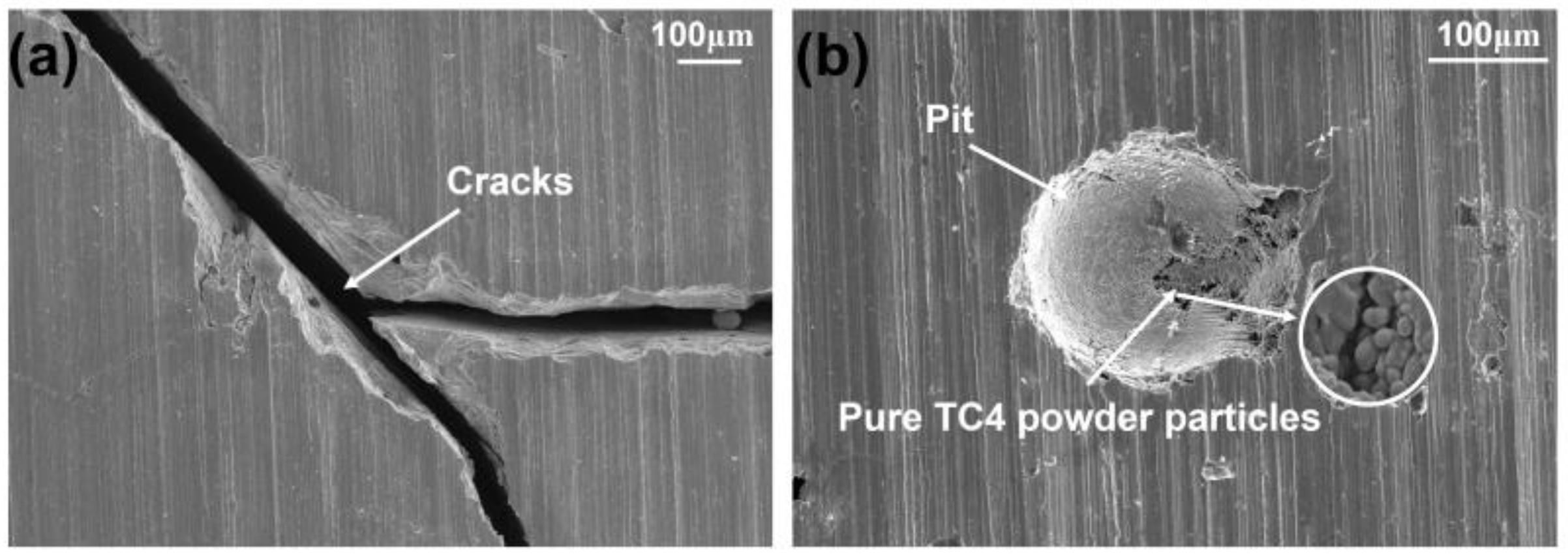
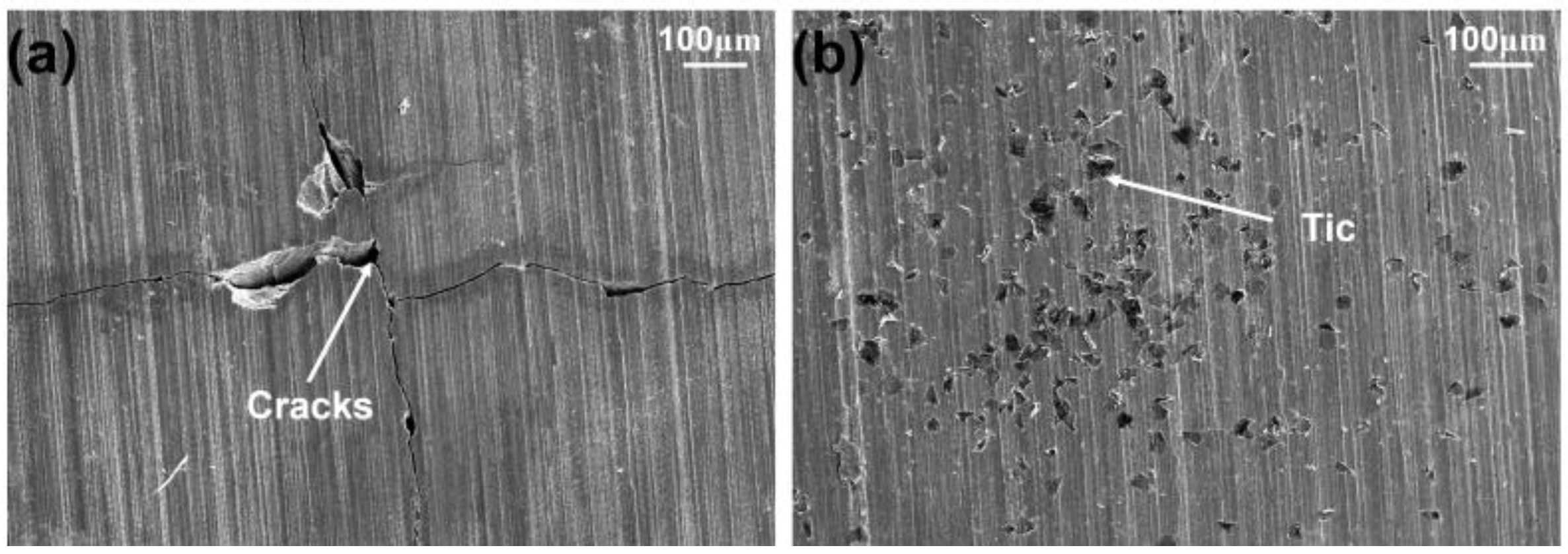
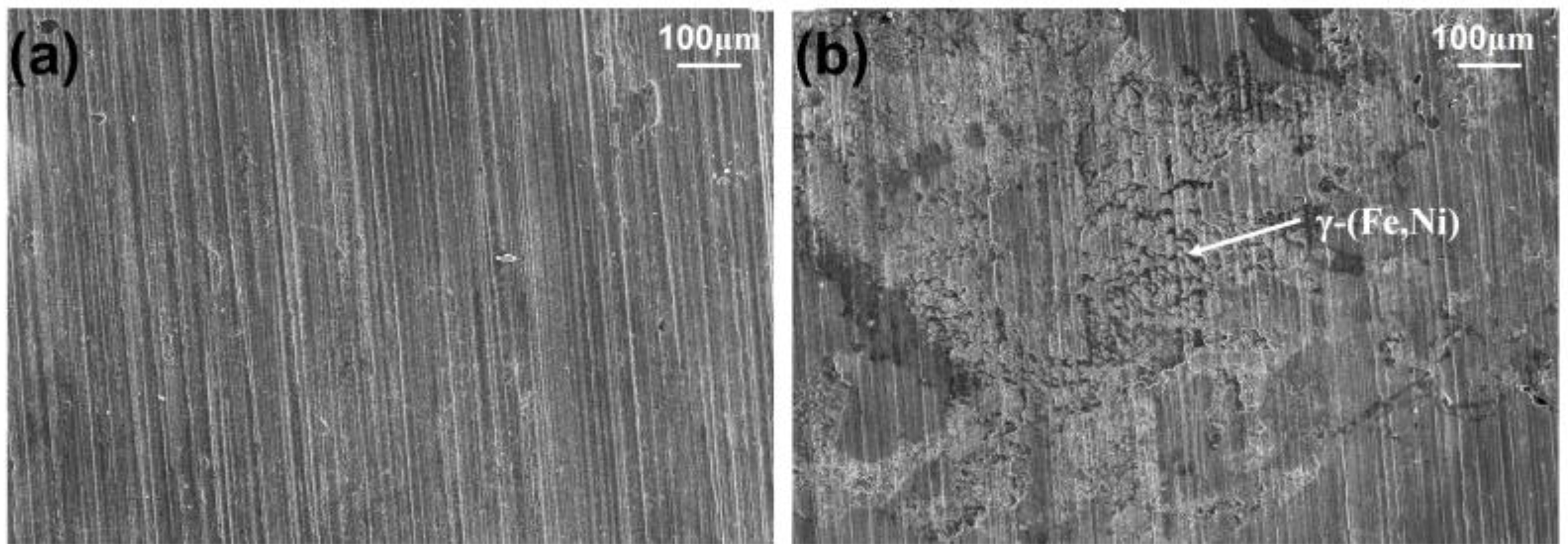
3.4. Surface Topography
4. Conclusions
Author Contributions
Funding
Institutional Review Board Statement
Informed Consent Statement
Data Availability Statement
Acknowledgments
Conflicts of Interest
References
- Abbott, A.; Abel, P.D.; Arnold, D.W.; Milne, A. Cost-benefit analysis of the use of TBT: The case for a treatment approach. Sci. Total Environ. 2000, 258, 5–19. [Google Scholar] [CrossRef]
- Schultz, M.P. Effects of coating roughness and biofouling on ship resistance and powering. Biofouling 2007, 23, 331–341. [Google Scholar]
- Dafforn, K.A.; Lewis, J.A.; Johnston, E.L. Antifouling strategies: History and regulation, ecological impacts and mitigation. Mar. Pollut. Bull. 2011, 62, 453–465. [Google Scholar]
- Salama, A.J.; Satheesh, S.; Balqadi, A.A. Antifouling activities of methanolic extracts of three macroalgal species from the Red Sea. J. Appl. Phycol. 2018, 30, 1943–1953. [Google Scholar] [CrossRef]
- Valeria Bers, A.; D’souza, F.; Klijnstra, J.W.; Willemsen, P.R.; Wahl, M. Chemical defence in mussels: Antifouling effect of crude extracts of the periostracum of the blue mussel Mytilus edulis. Biofouling 2006, 22, 251–259. [Google Scholar] [CrossRef]
- Guenther, J.; Walker-Smith, G.; Warén, A.; De Nys, R. Fouling-resistant surfaces of tropical sea stars. Biofouling 2007, 23, 413–418. [Google Scholar] [CrossRef]
- Lai, D.W.; Geng, Z.F.; Deng, Z.W.; Ofwegen, L.V.; Proksch, P.; Lin, W.H. Cembranoids from the soft coral Sinularia rigida with antifouling activities. J. Agric. Food Chem. 2013, 61, 4585–4592. [Google Scholar] [CrossRef]
- Schumacher, J.F.; Carman, M.L.; Estes, T.G.; Feiberg, A.W.; Wilson, L.H.; Callow, M.E.; Callow, J.A.; Finlay, J.A.; Brennan, A.B. Engineered antifouling micro topographies—Effect of feature size, geometry, and roughness on settlement of zoospores of the green alga Ulva. Biofouling 2007, 23, 55–62. [Google Scholar] [CrossRef]
- Qu, Y.Y.; Huang, H.F. Study of novel low surface energy antifouling coating prepared with silicon-modified acrylic resin and Nano-TiO2. Asian J. Chem. 2015, 4, 1212–1214. [Google Scholar] [CrossRef]
- Qiu, C.H.; Qi, Y.H.; Zhang, Z.P.; Gao, H. Study on fluorocarbon antifouling coatings with low surface energy. Mater. Sci. Forum 2011, 689, 445–449. [Google Scholar]
- Selim, M.S.; Yang, H.; El-Safty, S.A.; Fatthallah, N.A.; Shenashen, M.A.; Wang, F.Q.; Huang, Y. Super hydrophobic coating of silicone/β–MnO2 nanorod composite for marine antifouling. Colloids Surf. A 2019, 570, 518–530. [Google Scholar]
- Pu, X.; Li, G.J.; Huang, H.L. Preparation, anti-biofouling and drag-reduction properties of a biomimetic shark skin surface. Biol. Open 2016, 5, 389–396. [Google Scholar] [CrossRef]
- Guenther, J.; De Nys, R. Surface micro topographies of tropical sea stars: Lack of an efficient physical defence mechanism against fouling. Biofouling 2007, 23, 419–429. [Google Scholar] [CrossRef]
- Bai, X.Q.; Xie, G.T.; Fan, H.; Peng, Z.X.; Yuan, C.Q.; Yan, X.P. Study on biomimetic preparation of shell surface microstructure for ship antifouling. Wear 2013, 306, 285–295. [Google Scholar] [CrossRef]
- Callow, M.E.; Jennings, A.R.; Brennan, A.B.; Seegert, C.E.; Gibson, A.; Wilson, L.; Feinberg, A.; Baney, R.; Callow, J.A. Microtopographic cues for settlement of zoospores of the green fouling alga enteromorpha. Biofouling 2002, 18, 237–245. [Google Scholar]
- Vucko, M.J.; Poole, A.J.; Carl, C.; Sexton, B.A.; Glenn, F.L.; Whalan, S.; De Nys, R. Using textured PDMS to prevent settlement and enhance release of marine fouling organisms. Biofouling 2014, 30, 1–16. [Google Scholar] [CrossRef]
- Sun, K.; Yang, H.; Xue, W.; He, A.; Zhu, D.H.; Liu, W.W.; Adeyemi, K.; Cao, Y. Anti-biofouling super hydrophobic surface fabricated by picosecond laser texturing of stainless steel. Appl. Surf. Sci. 2018, 436, 263–267. [Google Scholar] [CrossRef]
- Giorgi, C.D.; Furlan, V.; Demir, A.G.; Tallarita, E.; Candiani, G.; Previtali, B. Laser micropolishing of AISI 304 stainless steel surfaces for cleanability and bacteria removal capability. Appl. Surf. Sci. 2017, 406, 199–211. [Google Scholar] [CrossRef]


| Element | Al | Fe | N | O | V | C | H | Ti |
|---|---|---|---|---|---|---|---|---|
| Mass fraction (%) | 5.5~6.5 | 0.25 | 0.05 | 0.13 | 3.5~4.5 | 0.08 | 0.012 | Bal. |
| Element | C | Cr | Si | B | Fe | Ni |
|---|---|---|---|---|---|---|
| Mass fraction (%) | 0.5 | 18.0 | 4.5 | 3.0 | 15.0 | Bal. |
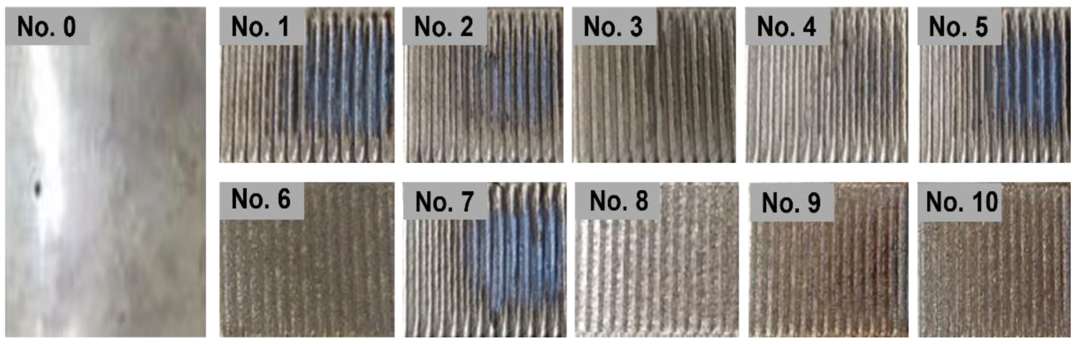
| Specimen Number | Powder Mass Ratio (Ni60:TC4) | Laser Power (W) | Laser Scanning Speed (mm/min) |
|---|---|---|---|
| 0 | 316L stainless steel | / | / |
| 1 | TC4 only | 1400 | 1200 |
| 2 | 2:8 | 1400 | 1200 |
| 3 | 3:7 | 1400 | 1200 |
| 4 | 4:6 | 1400 | 1200 |
| 5 | 3:7 | 1200 | 1300 |
| 6 | 3:7 | 1300 | 1300 |
| 7 | 3:7 | 1400 | 1300 |
| 8 | 3:7 | 1000 | 1000 |
| 9 | 3:7 | 1000 | 1200 |
| 10 | 3:7 | 1000 | 1400 |
Disclaimer/Publisher’s Note: The statements, opinions and data contained in all publications are solely those of the individual author(s) and contributor(s) and not of MDPI and/or the editor(s). MDPI and/or the editor(s) disclaim responsibility for any injury to people or property resulting from any ideas, methods, instructions or products referred to in the content. |
© 2023 by the authors. Licensee MDPI, Basel, Switzerland. This article is an open access article distributed under the terms and conditions of the Creative Commons Attribution (CC BY) license (https://creativecommons.org/licenses/by/4.0/).
Share and Cite
Wang, S.; Chen, Y.; Gu, C.; Sai, Q.; Lei, T.; Williams, J. Antifouling Coatings Fabricated by Laser Cladding. Coatings 2023, 13, 397. https://doi.org/10.3390/coatings13020397
Wang S, Chen Y, Gu C, Sai Q, Lei T, Williams J. Antifouling Coatings Fabricated by Laser Cladding. Coatings. 2023; 13(2):397. https://doi.org/10.3390/coatings13020397
Chicago/Turabian StyleWang, Shuwen, Yang Chen, Chunxing Gu, Qingyi Sai, Tianyu Lei, and John Williams. 2023. "Antifouling Coatings Fabricated by Laser Cladding" Coatings 13, no. 2: 397. https://doi.org/10.3390/coatings13020397